View allAll Photos Tagged FUT
Exemple d'immeuble de rapport cossu sis en face de la synagogue susmentionnée. Il fut construit en 1905 par Bedřich Bendelmayer et Karel Manda dans un style Sécession avec des touches d'historisme (un mix de néo-baroque / néo-renaissance selon moi). Il dépasse largement les standings de l'époque et proposait le confort maximal de l'époque avec notamment un ascenseur installé peu de temps après la construction. Les tourelles d'angles donnent une allure castral très mémorable et affirme une place proéminente dans ce "nouveau" quartier réinventé et privilégié (pour changé).
Sources : Wikipédia (CZ) && Monuments historiques (CZ)
Élisabeth-Rachel Félix, dite Rachel ou Mlle Rachel, est une actrice née le 21 février 1821 à Mumpf (Suisse) et morte le 3 janvier 1858 au Cannet (France). Grande tragédienne, elle fut un modèle pour Sarah Bernhardt.
Fille de Jacob Félix, colporteur ambulant juif né à Metz (1796-1872), et d'Esther-Thérèse Hayer née à Gerstheim (1798-1873), Élisabeth Félix naît à Mumpf en Suisse, dans une auberge où sa mère s'est arrêtée, trop fatiguée pour continuer jusqu'à Endingen, la seule localité de la région qui tolère le séjour de juifs. Elle est la seconde fille, après Sarah, du couple qui aura encore un fils, Raphaël, et trois filles[1].
Sa famille misérable erre de ville en ville à la poursuite d'une pitance que leur apportent la vente de colportage du père et celle des colifichets de la mère. Élisabeth Félix vit une partie de sa jeunesse à Hirsingue, dans le sud de l'Alsace (Sundgau).
Comme d'autres parents miséreux de cette époque, le père considère ses enfants comme une source de revenus : Élisabeth chante en s'accompagnant à la guitare avec sa sœur aînée Sarah, récite et mendie dans les rues des villes (d'Alsace, puis à Besançon, Lyon, Saumur…) que ses parents traversent avant leur arrivée à Paris en 1831, où la famille s'installe dans un mauvais logement rue des Mauvais Garçons, puis place du Marché-Neuf dans l'île de la Cité.
Analphabète, Élisabeth Félix suit alors les cours du musicien Alexandre-Étienne Choron et de Saint-Aulaire, et prend quelques cours d'art dramatique au Conservatoire. Pour subvenir aux besoins de sa famille, elle débute en janvier 1837 au théâtre du Gymnase. Delestre-Poirson, le directeur, lui fait prendre comme nom de scène Rachel, nom qu'elle adopte dès lors également dans sa vie privée. Auditionnée en mars 1838, elle entre au Théâtre-Français à l'âge de 17 ans. Son succès est immédiat. Elle débute dans le rôle de Camille d'Horace, dont la recette s'élève à 735 francs le premier soir, pour atteindre dix-huit jours plus tard, la somme de 4 889,50 francs.
Son interprétation des héroïnes des tragédies de Corneille, Racine et Voltaire la rendent célèbre et adulée, et remettent à la mode la tragédie classique, face au drame romantique. Elle créa un modèle nouveau d'actrice et de femme et fut une des femmes les plus célèbres de son siècle. Elle fut ainsi portraiturée, entre autres, par le sculpteur Jean-Auguste Barre.
Elle ne fait toutefois pas l’unanimité en raison, paradoxalement, de ses indéniables talents d’actrice. Ainsi, Victor Hugo qui « admire Rachel sans passion », aime citer le mot de Frédérick Lemaître[2] : « Rachel ? la perfection, et rien de plus ! »
En 1850, elle est reçue par le roi de Prusse qui lui fait élever dans le parc du château de l'île des Paons, près de Potsdam, une statue qui sera détruite par les nazis en 1935[1].
Elle eut deux fils : Alexandre (3 novembre 1844 - 20 août 1898), du comte Walewski, fils de Napoléon et de Marie Walewska, et Gabriel (26 janvier 1848 - ?) d'Arthur Bertrand, fils du maréchal Bertrand.
Rachel meurt le 3 janvier 1858 des suites d'une tuberculose, entouré par dix représentants du Consistoire de Nice et en prononçant la prière du Shema Israel. Lors de ses derniers moments, elle demanda à sa sœur Sarah d'appeler le grand rabbin de France, Lazare Isidor, à Paris pour venir à son chevet, qui arriva trop tard
“FUTURISTIC SPACE STATION WITH ION ROCKET SHIP IN ORBIT ABOVE ANTARCTICA
CONCEPT PAINTED BY WILLIAM C. HOUSE OF AEROJET-GENERAL”
11” x 13.875”.
A cropped version of the image is available at the excellent & informative ATOMIC ROCKETS website, specifically:
www.projectrho.com/public_html/rocket/images/spacestation...
William C. House - The Real Deal. Multiple extracts from disparate sources, sort of chronologically:
“One of the best known champions of the turborocket was William C. House, who proposed a cycle in 1949 while an employee of the Aerojet Engineering Corporation.* House examined a number of bipropellants including liquid hydrogen and liquid oxygen. He apparently proposed this combination to the Air Force in September 1953 and later, but nothing came of it (fig. 30, bottom):
history.nasa.gov/SP-4404/p123.jpg
“William C. House, director of NERVA (nuclear engine for rocket vehicle application) operations of the Aerojet-General Corporation, has been named a vice president of the company. He has been with Aeroject since 1949. Four months ago he received the Navy’s Meritorious Public Service Citation for his work on the Polaris missile.”
In 1956, the Awards Committee of the Aerospace Research Council selected Mr. House to become a Fellow Member of American Rocket Society, forerunner of the American Institute of Aeronautics and Astronautics (AIAA). Some of the others selected that year: William H. Pickering, director, Jet Propulsion Laboratory, California Institute of Technology; Simon Ramo, executive vice president, The Ramo-Wooldridge Corp., and Fred S. Whipple, chairman, Department of Astronomy, Harvard University & director, Astrophysical Observatory of the Smithsonian Institute.
mypatentprints.com/products/space-vehicle-patent-1960-spa...
Credit: ‘MyPatentPrints’ website
They’re ALL cool, but the “Fuel Station”, apparently a variant of this, is also courtesy of Mr. House:
paleofuture.com/blog/2013/9/12/space-taxis-air-sleds-and-...
Credit: “Paleofuture” website - which BTW is excellent…I’d almost forgotten about it!
From a 1969 citation:
“His education includes a B.S. (Aeronautical Engineering), California Institute of Technology. Prior experience includes service with Northrop Aircraft Company; U.S. Naval Engineering Experimental Station; Project SQUID, Princeton University; General Tire and Rubber Company of California and presently with Aerojet-General Corporation. His present position is Vice President and General Manager, Surface Effect Ships Division, Aerojet General Corporation.”
Finally, at least as of December 1972, Mr. House served on the board of directors of Caltech’s Alumni Association, being class of 1940.
Mr. House, as stated earlier, the real deal…rocket scientist…and talented artist!
Continue to RIP Good Sir and Thank You.
“A variety of Artificial Gravity/Mars Transfer Vehicle (AG/MTV) concepts were developed by the Martin Marietta Astronautics Group for NASA’s Mars Exploration Case Studies in 1988 to 1989. Each of these concepts used a large diameter (~39 to 46 m) aerobrake (AB) with a low lift to drag (L/D) ratio of ~0.2 for Mars Orbit Capture (MOC). These large ABs required assembly in LEO before being outfitted with habitation, auxiliary Photo-Voltaic Array (PVA) power and chemical propulsion system elements within their protective envelope. By rotating the AB about its central axis at different spin rates and mounting the habitat modules near the outer perimeter of the AB to increase the rotation radius, a range of centrifugal forces can be generated for the crew during the transit out to Mars and back…
However, initial concepts had several drawbacks, to include being very large, requiring significant orbital assembly for the AB and overall vehicle, with large Initial Mass in Low Earth Orbit (IMLEO) requirements. Additionally, problems of the five different concepts developed ranged from incompatible internal arrangements of varying habitation modules, the required movement of major pressurized mechanical joints, large propellant consumption to start/stop a tethered combination along with associated dynamic control problems & possible critical mechanical failures, even the possibility of crew isolation from systems enclosed within the AB e.g., Mars Descent/Ascent Vehicle (MDAV).
To avoid the deficiencies of those concepts, Martin Marietta proposed ‘Concept 6’, an AG/MTV design that used chemical propulsion and carried twin cylindrical Space Station Freedom (SSF) habitation modules whose long axes were oriented perpendicular to the longitudinal spin axis of the MTV—referred to as the Dumbbell B configuration. The hab modules were connected to a central logistics and docking hub by two pressurized tunnels each ~12.5 m long. Each hab module—designed to accommodate two to three crewmembers—had excess capacity so that either could serve as a safe-haven for the entire crew in case of an emergency. Attached to the Sun-facing side of each tunnel and hab module were ~30 and 75 m2, respectively, of PVAs producing ~26 kWₑ of electrical power for the spacecraft’s various systems. Once fully assembled, the rotation radius from the center of the logistics module to the floor of each hab module was ~17 m allowing centrifugal acceleration levels ranging from 0.38-g to 0.68-g for vehicle spin rates of 4.5 to 6 rpm. At a slightly higher spin rate of 7.25 rpm, 1-g could be achieved. The pressurized logistics hub also provided a shirt-sleeve environment and anytime crew access to the MDAV docked to the front of the vehicle.
The aft end Mars Orbit Capture Stage (MOCS) and forward Trans-Earth Injection Stages (TEIS) used four ~25 thousand-pound thrust liquid oxygen/liquid hydrogen (LOX/LH₂) RL10B-2 engines with an Iₛₚ of ~460 s. The MOCS also functioned as the TMI stage using propellant supplied from six surrounding drop tanks jettisoned in pairs as they are drained. The vehicle IMLEO at TMI was ~710.8 t.”
The above, at/per:
ntrs.nasa.gov/api/citations/20160014801/downloads/2016001...
The second paragraph consists of my paraphrasing, the rest is direct copy/paste.
The two capsules docked to the ‘top’ SSF habitation module are referred to as Earth Crew Capsule Vehicles (ECCV).
Who knew?!?
Did YOU!?!
I didn’t!!!
While I’ve never paid close attention to artificial gravity considerations with regard to a Mars Transfer Vehicle, I know I’ve NEVER seen this distinctive “dumbbell” design!
FINALLY, as if ALL of the linked to above/below, wasn’t enough…which it should be frankly, this beautiful work is by Martin Marietta artist Robert S. Murray. I like the clever framing of the AG/MTV by an obliquely viewed Arsia Mons (below) & Pavonis Mons (above), capped off by the tenuous upper atmosphere layer of haze visible on the Martian limb…nice, very nice.
A WIN:
www.paintingsbyrobertsmurray.com/about-me.html
Credit: “Paintings by Robert S. Murray” website
midcurrent.com/art/robert-s-murray/
Credit: “MIDCURRENT” website
“This is the horizontal version of lunar modular living and working quarters for use in our “Man On The Moon” program. Designed by scientists and engineers of the Lockheed Missiles and Space Company, each module is 18 feet in diameter. Each is fully-equipped and self-sufficient except for electrical power, which is supplied from a remote nuclear power source.”
Also associated with the image, thanks to Paul Vreede’s wonderful “SPACEX: GOLDEN ASTRONAUT” website, taken from David S. F. Portree’s superlative original blog:
“The self-contained lunar research station…showing its completely protected quarters, where a small party of lunar explorers can live and work.”
Also from Mr. Vreede’s site, courtesy the “Frank May collection”:
“A horizontal version of lunar modular living and working quarters for use in the “Man on the Moon” program. Conceived by scientists and engineers of the Lockheed Missiles & Space Company, Sunnyvale, California, each module is eighteen feet in diameter. Each is fully equipped and self-sufficient except for electrical power which is supplied from a remote nuclear power source shown in a crater at right. Solar flare protection chambers are provided at the base of the modules.”
Last, but NOT least, paraphrased from David S. F. Portree’s original blog:
“…Base modules would arrive on the moon fully outfitted with internal equipment. The permanent ELO base configuration, in place in 1975, would include five cylindrical horizontal modules on adjustable legs. Wing-like thermal radiators with removable panels for easy meteor damage repair would ensure that the air temperature inside the modules remained near 80 degrees Fahrenheit. Replaceable meteor shrouds would shield tubular crawlways linking the modules.
In a typical module, the main airlock would open onto a straight passage running the length of the lower deck. Hatches in the passageway floor would lead down into a cramped "solar flare protection cell" lined with water tanks. The lower deck would include sleep compartments for six astronauts, a galley, and environmental control systems, while the upper deck would contain a laundry, showers, a toilet, the central electrical control room, and laboratory/workshop space. Lockheed reckons that, in the moon's low gravity, the astronauts could move between the two decks without a ladder or stairs. The company also briefly considered a vertical base module configuration.
[Seen at the beginning of Mr. Portree’s blog, within Mr. Vreede’s presentation. This also explains/provides context to the previous references of “horizontal version”.]
Without belaboring the boundless goodness going on within this detailed & exquisite masterpiece, the above allusion to meteor damage is actually depicted in the image by the Astronaut on EVA, seen transferring the damaged radiator panel (puncture hole clearly visible) into the airlock for repair. Its former location evident by the gap in the panels & nearby ladder on the left rear module.
Finally, as if the above wasn’t enough, the names of the responsible parties are visible. Not surprisingly, they are William Collopy & Anthony Saporito, whom I believe to be protégés of the maestro, Ludwik Źiemba.
Furthermore, a WIN on a WIN; their respective responsibilities are included! If I’ve got it right, “DRAWN” means just that…the lines, borders & boundaries between objects depicted. “RENDERED” being the process of giving the work body, depth & perspective, through shading, coloring…and a bunch of other things I’m probably too dense, ignorant actually, to recognize. Looking back on other identified collaborative works by these three artists - and this is for only my edification - is “DRAWN”, followed by “RENDERED” the standard/conventional order of march/merit if/when not specified? It would make sense.
Bottom Line: A meticulous masterpiece.
Mr. Vreede's site:
www.triangspacextoys.info/SpGAorig/MnBs_OrF/MnBs_OrP.html
See also:
www.secretprojects.co.uk/threads/lockheed-moon-base.10309/
Credit: SECRET PROJECTS website
“SOLAR POWER SATELLITE----An artist’s concept depicting the initial fabrication of a Solar Power Satellite structural member. The Solar Power Satellite will be located in geosynchronous orbit some 36,000 miles above the Earth.”
Although I don't see a signature, the artist is likely 'R. J. Dubois', who is responsibly for at least photos 'S-76-24707' & 'S-76-24712', linked to below.
I wonder how many total comprised this series. I do know it chronologically/sequentially goes back at least to 'S-76-24703', which however is NOT by Mr./Ms. Dubois, linked below as well.
The finished lunar base: consisting of - laboratories, astronauts' quarters, storage - are covered with a layer of lunar regolith. A radio telescope can be seen, placed in a small lunar crater.
The above is my butchering of Swedish, of the abbreviated photo caption, and there’s no way I’m translating the rest of it. Suffice it to say that there’s obviously a whole lot more than that going on, possibly as a result of a temporal rift that brought this mix of disparate spacecraft and the like all together in this area on/near the moon.
Unfortunately, no signature is visible. It’s really striking & has a Roy Scarfo look to it. Based on the appearance of the Lunar Module & derivatives, I think the original artwork was ~4/4+ years prior to the date stamp on the verso.
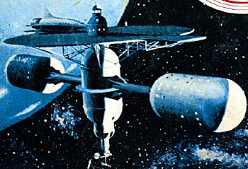
“NUCLEAR-ION ROCKET ENROUTE TO VENUS
Long range interplanetary research of the future is depicted in this concept by W. C. House, Director, Systems Management, Aerojet-General Corporation of a large nuclear-ion rocket on its way to the planet Venus. The rocket, conceived by House, would be between 25 and 30 feet in diameter and approximately 150 feet long, or about the size of a modern submarine cut in half. It is pictured above at altitude of 4,000 miles over Western Europe at 4:45 a.m. Greenwich Mean Time on August 20. Its position is 40 degrees east longitude and 30 degrees north latitude. The wings on the rocket, which have been elongated for artistic purposes, probably would be stubby projections retractable in flight but necessary to effect landings on other planets or return to earth.”
What an oddly & amusingly precise description of a spacecraft’s position/location in both time & space – IN AN ARTIST’S CONCEPT.
"Le Château de Chantilly abrite l’une des plus riches bibliothèques de France. Les trésors accumulés par les différents propriétaires de Chantilly ont été complétés et magnifiés avec passion par le duc d’Aumale, qui fut le plus grand bibliophile de son temps. Le Cabinet des livres aménagé par l’architecte Honoré Daumet à la fin du XIXe siècle forme un écrin pour les manuscrits des princes de Condé et les trésors du duc d’Aumale. Un hommage y est rendu au Grand Condé dont le buste, par Coysevox, attire le regard sur la cheminée, tandis que les armoiries des compagnons d’armes du prince ornent le plafond"
(texte tiré du site chateaudechantilly.fr)
Cet édifice fut probablement érigé sur l’emplacement d’un monastère construit vers 650 par le moine irlandais saint Fursy. L’Histoire et les siècles ont été témoins de ses nombreuses transformations, restaurations et reconstruction. En 1205, les travaux s’engagent sur les bases d’un projet grandiose : une abbatiale d’une longueur de 110 mètres et d’une hauteur sous voûte de 27 mètres. Malheureusement, il se limitera au chœur accolé à la nef de l’édifice antérieur. Après la disparition de cette nef au XVIIe siècle, on construit un clocher porche puis un deuxième qui s’ouvre aujourd’hui sur un chœur imposant : 48 m de long et 37 m de large. Les chapelles de profondeurs différentes rythment son chevet. Le mur ouest conserve des vestiges de la nef du XIIe siècle, de part et d’autre du buffet d’orgue. Dans la chapelle dédiée à la Vierge Marie, se sont déroulés deux événements qui ont marqué l’histoire de l’église abbatiale. En 1126, décimée pour la deuxième fois en un siècle par le terrible « mal des ardents » (forte fièvre due à un cham- pignon de l’ergot de seigle), la population se porte en masse à la chapelle et obtient par ses
prières que le mal cesse.
A trois reprises, Jeanne d’Arc a foulé le sol latignacien. En 1430, elle mêle ses prières à celles de jeunes filles et un enfant qu’on pensait mort depuis 3 jours retrouve vie, le temps de lui donner le baptême. C’est à ce titre que quelques siècles plus tard, Jeanne d’Arc fut canonisée. A noter que
Lagny-sur-Marne a rejoint le cercle prisé des Villes Johanniques en 2013.
Les plus anciens vitraux réalisés par Claudius Lévêque datent de la deu- xième moitié du XIXe siècle. Ceux d’une tonalité bleue, situés près de la
chapelle de la Vierge Marie, sont une création de Calixte Poupart inau-
gurés en 1955.
Depuis 1886, l’église abbatiale est classée Monument Historique.
Porsche 356
Elle fut la troisième voiture de la marque allemande Porsche. Conçue par Ferry Porsche sur les bases mécaniques de la Volkswagen Coccinelle (par souci d'économie) et dessinée par Erwin Komenda.
Marque Porsche
Années de production 1948-1965
Production 76 313 exemplaire(s)
Classe Voiture de sport
Moteur et transmission
Moteur(s) Essence : 4 cylindres à plat (boxer) refroidi par air de 1,1 L à 2 L (40 ch à 130 ch)
Transmission Propulsion
Poids et performances
Poids à vide 680 - 900 kg
Châssis - Carrosserie
Carrosserie(s) coupé, cabriolet, speedster
Dimensions
Longueur 4 001 mm
Largeur 1 670 mm
Hauteur 1 330 mm
Seen at the Redbourn Classics Motor Show in Redbourn, Hertfordshire on 04 September 2021.
FUT721C is a 1965 MG MGB.
First registered in March 1965.
“The explorers are ready to leave Mars. The ship’s aft end is used as a launching platform for the escape to Earth.”
One of the many gorgeous Boeing/USAF depictions of Philip Bono’s vision for the exploration of Mars.
I believe the original printing of the photo to be circa 1960, which this may or may not be. The handwritten year on the verso may suggest it to be a “reissue”, possibly accounting for the less than crisp image. Or it may just represent the year it was (re?)released for press purposes. ¯\_(ツ)_/¯
There are several dulled blotches on the surface, fortunately only visible when viewed obliquely and at the appropriate angle with respect to the light source.
To me, the signature might be "Coffin". If so, maybe James L. Coffin? Per the ARCHIVES WEST website:
"James Coffin (1931-2007), came to Seattle to work for Boeing in 1962 after attending ArtCenter in Los Angeles and working as an art director in Washington, DC. In 1964, he started his own advertising business, later entering animation through title design. A self-taught character animator, he produced work for Weyerhauser, Boeing, AT&T, Farrell's, Pacific Northwest Bell, and Fred Meyer as well as interactive installations, educational films and rotoscoped chalk animation for the Seattle Opera’s 1972 premiere of “The Black Widow.” Coffin maintained an active studio through the 1970s, employing up to ten other artists at a time. Coffin also was noted for his course in 2-D animation offered to Seattle artists and filmmakers."
At:
archiveswest.orbiscascade.org/ark:/80444/xv69714
Although the years of Boeing employment cited doesn't quite match up with my time estimation, it's still worthy of consideration.
Pertinent information & additional images, at David S. F. Portree’s superlative “No Shortage of Dreams” blog:
spaceflighthistory.blogspot.com/2015/09/the-martian-adven...
Finally:
I think all of the SDASM Bono/Boeing Mars glider images here on this image hosting service - of those that have their original photo ID visible - end with "R1". Likely/possibly being "Revision 1"?
Sure enough, when you compare my posted photos to the SDASM versions of the same, the markings on the wing of the glider are "USAF", along with the USAF roundel. The equivalent SDASM "R1" images bear the U. S. flag and "USA". It seems that the “R1” images were "demilitarized".
“A nuclear-propelled spacecraft, shown being assembled in an orbit around the earth, prepares for take-off to Mars. An orbital assembly team is depicted swinging a second stage assembly into position, using space tugs. This second stage will brake the craft into its orbit around Mars. A cluster of four cylinders (upper right), will house the astronauts during the long Martian voyage. At right angles to the astronauts’ quarters are temporary living quarters of the assembly team, which will spend nearly four months in earth orbit assembling the spacecraft for the Mars mission. This “typical” Mars mission was conceived by scientists at the Westinghouse Electric Corporation’s Astronuclear Laboratory and was described by Dr. William M. Jacobi of Westinghouse, at the American Institute of Astronautics and Aeronautics meeting. Heart of the system is a nuclear reactor (housed in the engine at lower left) which Westinghouse is developing in connection with the Rover Program, the nation’s effort to develop nuclear rocket propulsion systems for advanced space missions. The reactor will be incorporated into the NERVA (Nuclear Engine for Rocket Vehicle Application) engine under development by Aerojet-General Corporation for the AEC-NASA Space Nuclear Propulsion Office, based on a concept originated by the Los Alamos Scientific Laboratory.”
Additionally. It’s very long but incredibly informative, enlightening & pertinent, with LOTS of content I wasn’t aware of. Not to mention, who knows how long it’ll continue to be available online:
“Before his death, renowned science fiction writer, inventor, and futurist Arthur C. Clarke (1917–2008) confidently declared the space age had not yet begun, and would only commence when reliable nuclear-powered space vehicles become available to drastically reduce the cost of moving humans and heavy payloads from the surface of the earth to the farthest reaches of the solar system. It is a little appreciated fact that Pittsburgh’s Westinghouse Electric Company played a central role in bringing that vision much closer to reality through its participation in the Nuclear Energy for Rocket Vehicle Applications (NERVA) program between 1959 and 1973. With recently renewed interest in the human exploration of Mars and destinations in the outer solar system, attention is once again focusing on the remarkable accomplishments that Westinghouse made in the development of the largely untapped potential of the nuclear thermal rocket.
As early as 1949, the Los Alamos National Laboratory, Los Alamos, New Mexico, conducted research to develop a solid core nuclear thermal rocket engine to power intercontinental ballistic missiles. The idea of a nuclear-powered rocket had already captured the imagination of many serious science fiction writers, evidenced by Robert A. Heinlein’s 1948 novel Space Cadet that featured a sleek nuclear-powered rocket ship that inspired the 1950 CBS television series Tom Corbett, Space Cadet, starring Frankie Thomas (1921–2006). With encouragement from science advisor Willy Ley, in 1951 Joseph Lawrence Greene, writing under the pseudonym Carey Rockwell at the publishing house of Grosset and Dunlap, launched Tom Corbett, Space Cadet, a juvenile novel series that fired the imagination of an entire generation of America’s youth with images of a streamlined manned single-stage-to-deep space atomic-powered rocket called the Polaris.
Similar to the nuclear rocket engine eventually developed under the NERVA program, the Polaris employed turbo-pumps to supply propellant to a uranium-fueled reactor core. Virtually all of the single-stage rockets of the golden age of science fiction were described at the time as using some form of atomic energy for propulsion. In a classic example of scientific theory inspiring art and, in turn, inspiring practical engineering concepts, by 1957 Los Alamos Laboratory had acquired a test facility at Jackass Flats, Nevada, to test the first KIWI series of nuclear rocket engines as part of Project Rover. Because these were ground tests rather than actual flight tests, the early engines were named after the flightless Kiwi bird endemic to New Zealand. The trials were conducted with the engines mounted upside down on their test stands with the rocket plume firing upward into the atmosphere.
In 1959, the Westinghouse Electric Company of Pittsburgh and its Bettis Atomic Power Laboratory in nearby West Mifflin, also in Allegheny County, were busy building nuclear reactors for the U.S. Navy and had also designed the nation’s first commercial nuclear power plant at Shippingport, Beaver County, that went online in December 1957. In anticipation of landing more lucrative government contracts, John Wistar Simpson, Frank Cotter, and Sidney Krasik convinced Westinghouse CEO Mark W. Cresap Jr. in 1959 to approve the creation of the Westinghouse Astronuclear Laboratory (WANL) to investigate the feasibility of building nuclear rocket engines.
Authorized in May 1959, WANL officially became a Westinghouse division on July 26, 1959, and consisted of just six employees with Simpson at the helm. Krasik, a Cornell University physicist, served as technical director and Cotter worked as Simpson’s executive assistant and marketing director. Born in 1914, Simpson graduated from the United States Naval Academy, Annapolis, Maryland, joined Westinghouse in 1937, and earned an MS from the University of Pittsburgh in 1941. Working in the switchgear division of Westinghouse’s East Pittsburgh plant, Simpson helped develop electric switchboards that could survive the extreme impacts experienced by naval vessels under bombardment in the Pacific Theater during World War II. In 1946, he took a leave of absence from Westinghouse to work at Oak Ridge National Laboratory in Oak Ridge, Tennessee, to familiarize himself with atomic power. Upon his return three years later, he became an assistant manager in the engineering department of Westinghouse’s Bettis Atomic Power Laboratory. He subsequently managed the construction of the Shippingport Atomic Power Station in 1954 and the following year was promoted to general manager of the Bettis Laboratory. He was elected a Westinghouse vice president in 1958. By 1959 Simpson and his team had become enthusiastic about taking on the new challenge of building nuclear-powered rockets to explore the solar system.
WANL was first headquartered in a shopping mall in the Pittsburgh suburb of Whitehall. By 1960 its staff and the leaders of Aerojet General had pooled resources to compete for the lucrative NERVA program contract from NASA’s Space Nuclear Propulsion Office (SNPO). Aerojet and Westinghouse won the contract to develop six nuclear reactors, twenty-eight rocket engines, and six Rocket In Flight Test (RIFT) flights the following year. With a substantial contract in hand, WANL increased its staff to 150 and relocated to the former site of the Old Overholt Distillery. By 1963, Westinghouse and its collaborators employed eleven hundred individuals on the project, based near the small town of Large, thirteen miles south of Pittsburgh in Allegheny County. Large was named for a former distillery founded during the early nineteenth century by Joseph Large. Together, Aerojet and Westinghouse developed the NRX-A series of rocket test engines based on an 1120 megawatt Westinghouse reactor. Assembled at Large, the reactors were loaded on rail cars for delivery to the nuclear test facility at Jackass Flats for field testing.
The initial objective of the NERVA program was to build a rocket engine that could deliver at least eight hundred seconds of specific impulse, fifty-five thousand pounds of thrust, at least ten minutes of continuous operation at full thrust, and the ability to start-up on its own with no external energy source. Seventy pounds per second of liquid hydrogen pumped from the propellant tank into the reactor nozzle would provide regenerative cooling for the rocket nozzle. The cylindrical graphite core of the nuclear reactor was surrounded by twelve beryllium plates mounted on control drums to reflect neutrons. The drums, also containing boral plates on opposite sides to absorb neutrons, were rotated to control the chain reaction in the core. The core consisted of clusters of hexagonal graphite fuel elements, the majority of which consisted of six fueled element sectors and one unfueled sector. The fuel, pyrographite-coated beads of uranium dicarbide, was coated with niobium carbide to prevent corrosion caused by exposure to hydrogen passing through the core. Each fuel rod cluster was supported by an Inconel tie rod that passed through the empty center section of each fuel rod cluster, and a lateral support and seal was used to prevent any of the hydrogen from bypassing the reactor core. Inconel is a high-temperature alloy, one version of which was being used at the time as the skin on the famous X-15 rocket plane.
The solid core nuclear thermal rocket used highly enriched uranium embedded in a graphite matrix. As the highly fissionable uranium 235 atoms absorb a neutron they split to form lighter elements, more neutrons, and a large amount of thermal energy. The nuclear rocket uses the thermal energy generated by a nuclear chain reaction to heat hydrogen, forced through narrow channels in the reactor core. The hydrogen propellant is delivered under pressure to the reactor core using turbo-pumps. The nuclear chain reaction in the reactor core causes the hydrogen to become superheated and expelled through the rocket nozzle at extremely high velocity as an explosively expanding reaction mass resulting in a high specific impulse of 825 seconds. In a chemical rocket, where a fuel (such as liquid hydrogen) and an oxidizer (such as liquid oxygen) are brought together and burned in a combustion chamber, the maximum specific impulse achievable is only about 450 seconds. Specific impulse is a measure of efficiency of a rocket and is defined by Konstantin Tsiolkovsky’s rocket equation as the pounds of thrust produced for the pounds of fuel consumed per second and is expressed in seconds.
With a high specific impulse, the ability to conduct multiple shutdowns and restarts, and a highly favorable energy to weight ratio, the nuclear rocket was the kind of vehicle that the early rocket pioneers Robert Goddard, Herman Oberth, Wernher von Braun, and Tsiolkovsky had long envisioned. As early as 1903, Tsiolkovsky, a Russian mathematics teacher, had hoped that it might be possible to somehow extract atomic energy from radium in order to power a rocket, but it was not until 1938 that Otto Hahn in Germany first succeeded in causing uranium to fission. Hahn’s former colleague Lise Meitner, living in exile in Sweden, realized the significance of what he had done—and the door to the atomic age flung open!
The power density of traditional chemical rockets is puny compared to the extraordinarily high power density of a nuclear rocket engine. Chemical rockets consist of numerous throwaway stages and require an enormous volume of their mass devoted to carrying both a propellant and an oxidizer. A nuclear rocket can be built as a single-stage vehicle, and requires no oxidizer because it heats a propellant that serves as the reaction mass, and is also able to undergo numerous shutdowns and restarts, making lengthy missions to the ends of the solar system both possible and economical. While the inefficiencies inherent in chemical rockets result in nominal costs of $3,500 to $5,000 per pound to deliver payload to low earth orbit, the more favorable propellant to payload mass ratio of the nuclear rocket promises costs in the range of just $350 to $500 per pound.
After radiation safety concerns were raised by SNPO at NASA over launching nuclear-powered rockets directly from the earth’s surface, von Braun at the Marshall Space Flight Center in Huntsville, Alabama, developed a proposal to boost a nuclear-propelled second-stage NERVA rocket to the edge of space using his Saturn V first-stage before firing the nuclear rocket engine after it was well above the densest part of the atmosphere. There is some debate as to whether this precaution is necessary for a well-designed nuclear rocket, but the prevailing cautiousness regarding anything nuclear renders it unlikely that direct ascent from the earth’s surface will be found acceptable anytime soon. The early NERVA rocket engine tests were, in fact, open atmospheric tests.
Westinghouse Astrofuel’s fabrication plant at Cheswick, Allegheny County, supplied nuclear fuel for the NERVA project. Fuel element corrosion was tested by heating the fuel elements by their own resistance, first at the Large site, and later at a new facility at Waltz Mill, Westmoreland County. In order to ensure fuel corrosion resistance and the stability of dimensional tolerances to several thousandths of an inch, the materials in the core elements were extruded into a bar possessing a hexagonal cross section having nineteen longitudinal holes. The extrusion was then polymerized, baked at a low temperature, and graphitized at a higher temperature of about 2200 degrees Centigrade. The resulting unfinished fuel element was subjected to a high-temperature chemical vapor process to coat the surfaces of the longitudinal channels with a gas mixture of niobium pentachloride, hydrogen, and methane. This mixture reacted with the graphite to form a niobium carbide coating intended to prevent corrosion of the core when it was exposed to the hydrogen propellant. The great challenge was to achieve a good match between the thermal expansion coefficients of the graphite and the niobium carbide to prevent cracking.
On September 24, 1964, the NRX-A2 established proof of concept by providing six minutes of power. By April 23, 1965, Aerojet and Westinghouse tested the NRX-A3 nuclear rocket engine at full power for sixteen minutes and demonstrated a three-minute restart. Pulse cooling was also introduced at this time in which bursts of LH₂ were used to cool the reactor core. This was followed by a test of the NRX/Engine System Test (EST) engine equipped with Aerojet’s new nozzle and turbo-pump mounted next to the engine in place of the earlier Rocketdyne pump that had been housed separately behind a concrete wall. This permitted full operational testing of all of the equipment in a high radiation environment typical of an actual spaceflight. In 1966, Aerojet and Westinghouse commenced an additional series of tests to demonstrate ten startups on the NRX-A4/EST and full power operation of the NRX-A5 engine for two periods totaling thirty minutes of operation. On December 13, 1967, the NRX-A6 reached sixty minutes of operation at full power. According to data compiled by Aerojet and Westinghouse, on June 11, 1969, the XE engine was started twenty times for a total of three hours and forty-eight minutes, eleven of which were at full power. By 1970, the proposed NERVA I concept vehicle that evolved out of this work was projected to be capable of delivering 1500 MW of power and 75,000 pounds of thrust. It also had a projected lifetime runtime of ten hours and could be started and stopped 60 times while delivering 825 seconds of specific impulse for each hour of continuous operation. Especially encouraging was the fact that it was projected to have a total weight of less than fifteen thousand pounds.
Capable of starting up on its own in space and reaching full power in less than one minute, the design operating temperature of the reactor was 2071 degrees Centigrade and its reliability was projected to be at least 0.997. The .003 projected failure rate covered all forms of operational deficiencies, not just a catastrophe such as a crash or explosion. In one test conducted at Jackass Flats on January 12, 1965, a KIWI-TNT nuclear rocket engine reactor was intentionally exploded to more accurately assess the consequences and cleanup implications of a truly catastrophic launch pad accident. Off-site radiation from the test was judged to be statistically insignificant, adding just 15 percent to an individual’s average annual exposure at a distance of 15 miles from ground zero, and technicians were able to thoroughly clean up the site at ground zero within a matter of weeks.
Aerojet and Westinghouse prepared to begin construction of five reactors and five NERVA I rocket test engines for actual flight testing from the Kennedy Space Center on Merritt Island in Florida beginning in 1973, the year the federal government terminated the NERVA program. Total government expenditure by that time on the combined Rover/ NERVA program from 1955 to 1973 had reached more than $1.45 billion (equivalent to roughly $4.5 billion today). As a result of the cancellation of this program, a NASA plan to use a NERVA-type vehicle to place humans on Mars by 1981 was quietly shelved.
Based on the rapid improvements made to the design of the NRX engines in little more than a dozen years, it has been argued that with subsequent improvements in materials science, coupled with a better understanding of physics, the solid core nuclear thermal rocket would have been improved to the point where it could have delivered at least 1000 seconds of specific impulse, 3000 MW of power, and been capable of perhaps 180 recycles. Such a rocket would have been capable of continuously cycling back and forth to Mars about fifteen times with each transit taking as little as 45 to 180 days depending upon the transfer orbit configuration chosen, instead of the six to nine months required for a chemical powered rocket to make the same trip. The faster transit would actually lower astronauts’ exposure to radiation from cosmic rays, the van Allen radiation belts, and solar flares; it would also make it possible to launch heavier vehicles with larger crews and better shielding against cosmic radiation.
After the NERVA program ended, the Westinghouse Astronuclear Laboratory in Pittsburgh continued to work on several other projects, including the development of a nuclear-powered artificial heart. Amidst a changing political climate concerned with finding “green” energy sources, the laboratory became the Westinghouse Advanced Energy Systems Division (AESD) in 1976. Engineers at AESD experimented with a heliostat and worked on the Solar Total Energy Project in Shenandoah, Georgia, that used five acres of solar collectors to power a knitting factory. AESD also worked on a prototype for a magnetohydrodynamic system which reuses exhaust gases to increase the electrical output of a coal-powered plant by 30 percent. Following Westinghouse’s shuttering of AESD, several former employees formed Pittsburgh Materials Technology Inc. in 1993 at the former Westinghouse Astronuclear Laboratory. Pittsburgh Materials Technology specializes in producing high temperature specialty metal alloys for government and industrial customers.
During the 1970s, Westinghouse Electric Corporation sold its home appliance division and oil refineries, and in 1988 closed its East Pittsburgh manufacturing plant. In 1995, the company purchased CBS and the following year acquired Infinity Broadcasting. Renaming itself CBS Corporation in 1997, it sold off the nuclear energy business to British Nuclear Fuels Ltd. which, in turn, sold it to Toshiba in 2006. Under the wing of Toshiba, the nuclear energy business continues to operate under the name Westinghouse Electric Company and, because of rapid expansion in overseas demand for nuclear power plants, moved its corporate headquarters in 2009 to a new larger campus in Cranberry Township, Butler County.
In 1963, when Cresap died, Simpson was responsible for eighteen major Westinghouse divisions. Six years later he became president of Westinghouse Power Systems. He earned the Westinghouse Order of Merit and was elected to the National Academy of Engineering in 1966. In 1971, he won the prestigious Edison Medal. A member of the board of governors of the National Electric Manufacturers Association (NEMA) and chairman of NEMA’s Power Equipment Division, he was also a fellow of the American Nuclear Society where he served on the board of directors, on the executive committee, and as chairman of the finance committee. In 1995, the American Nuclear Society published his book Nuclear Power from Underseas to Outer Space, in which he recounted his experiences at Westinghouse. The book includes a detailed description of the company’s astronuclear program. Simpson died at the age of ninety-two on January 4, 2007, at Hilton Head, South Carolina.
The Westinghouse Astronuclear Laboratory was a product of an era of bold optimism in the promise of science and technology to solve problems and to bring to fruition a vision long shared by rocket pioneers Sergei Korolev, Stanislaw Ulam, Freeman Dyson, Tsiolkovsky, Goddard, Oberth, von Braun, and many others to eventually spread mankind across the vast solar system. Much of the science fiction of the era, such as the Tom Corbett television and juvenile novel series, was grounded in hard science as it was understood at the time. Overtaken by the social and political upheavals that accompanied the growing disillusionment with the Vietnam War and social dissension at home, the NERVA program nonetheless achieved remarkable successes that were ultimately cut short by shifting political events and a narrowing of national horizons. Despite a long hiatus, those successes are now inspiring a new generation of aerospace engineers to once again think boldly and embrace the difficult challenges articulated by President John F. Kennedy, a strong early supporter of the NERVA Program, at Rice University, Houston, Texas, in 1962: “We choose to go to the moon in this decade, and do the other things, not because they are easy, but because they are hard.”
The collaboration of Westinghouse Electric and Aerojet General in tackling the difficult work of developing a viable solid core nuclear thermal rocket engine is a down payment on the eventual human exploration and settlement of the solar system. The full utilization of such nuclear technology will make possible the fulfillment of the dream first enunciated by Tsiolkovsky who more than a century ago proclaimed, “The earth is the cradle of mankind, but a man cannot live in the cradle forever.” Nurtured by the dreamers in the cradle of western Pennsylvania’s Three Rivers Valley for a brief but shining period of fourteen years, the dream of one day boldly setting off into the new frontier moved a little closer to reality.”
At:
paheritage.wpengine.com/article/aiming-stars-forgotten-le...
Credit: “PENNSYLVANIA HERITAGE” website
Although no signature is visible, to me, there’s a Ludwik Źiemba influence visible, although not as exquisitely detailed or precise. Maybe by one of his protégés? ¯\_(ツ)_/¯
Le pont couvert de Saint-Placide fut construit en 1926 afin de permettre d’enjamber la rivière du Bras du Nord-Ouest. De style architectural « town québécois » ou « élaboré », il est le dernier de ce genre à exister dans la grande région de Québec. Panneau d’interprétation.
Le château fut construit sur les ruines d'un oppidum celte, à un endroit où la présence humaine remonte à l'époque néolithique. Les Romains y établirent plus tard un camp fortifié. Au début du VIIIe siècle, Pépin de Landen éleva une villa au même endroit.
Vers 844, Adelard, comte de La Roche, y établit le premier château. Après la mort de Henri de la Roche en 1152, le comté passa à Henri l'Aveugle comte de Namur et à sa mort en 1196 à sa fille Ermesinde de Luxembourg et ainsi à la lignée des comtes de Luxembourg.
Au XIVe siècle, les habitants de La Roche furent autorisés par Jean l'Aveugle, comte de Luxembourg, à protéger leur ville par une muraille et des tours qui vinrent ainsi renforcer le système défensif du château.
L'importance stratégique du château fort n'échappa pas à Louis XIV. Celui-ci investit les lieux de 1681 à 1688 et en profita pour le faire transformer et renforcer par un disciple de Vauban. Toutefois, ces travaux ne lui profitèrent guère puisque le château fut remis entre les mains des vainqueurs de la guerre de Succession d'Espagne et ceux-ci le négligèrent peu à peu.
Les malheurs du château ne faisaient que commencer puisqu'en 1721, il fut gravement endommagé par un incendie provoqué par la foudre. Joseph II d'Autriche le fit ensuite démanteler. Il fut la proie des vandales au XIXe siècle et pour couronner le tout, subit, lors de la bataille des Ardennes, le terrible bombardement de décembre 1944.
Fort heureusement pour les passionnés d'histoire et d'architecture, les ruines du château de La Roche-en-Ardenne n'en constituent pas moins, encore aujourd'hui, un bel exemple d'architecture militaire à travers les âges.
The castle was built on the ruins of a Celtic oppidum, in a place where human presence dates back to the Neolithic period. The Romans later established a fortified camp there. At the beginning of the 8th century, Pépin de Landen built a villa on the same site.
Around 844, Adelard, Count of La Roche, established the first castle there. After the death of Henri de la Roche in 1152, the county passed to Henri l'Aveugle, Count of Namur and on his death in 1196 to his daughter Ermesinde of Luxembourg and thus to the line of the Counts of Luxembourg.
In the 14th century, the inhabitants of La Roche were authorized by Jean l'Aveugle, Count of Luxembourg, to protect their city with a wall and towers which thus reinforced the defensive system of the castle.
The strategic importance of the fortified castle did not escape Louis XIV. He invested the place from 1681 to 1688 and took advantage of it to have it transformed and reinforced by a disciple of Vauban. However, this work did not benefit him much since the castle was handed over to the victors of the War of the Spanish Succession and they gradually neglected it.
The misfortunes of the castle were only just beginning since in 1721, it was seriously damaged by a fire caused by lightning. Joseph II of Austria then had it dismantled. It fell prey to vandals in the 19th century and to top it all off, suffered, during the Battle of the Bulge, the terrible bombardment of December 1944.
Fortunately for history and architecture enthusiasts, the ruins of the castle of La Roche-en-Ardenne nevertheless constitute, even today, a fine example of military architecture through the ages.
Les vitraux de Saint-Vincent. En 1939, prévoyant le pire, l'Administration prit la décision de déposer tous les vitraux anciens de l'église Saint-Vincent. Après classement en bonne et due forme, ils furent envoyés au donjon de Niort, dans les Deux-Sèvres. Les vitraux des XVIIIe et XIXe siècles restèrent en place. Avec l'église, ils furent réduits en miettes lors du bombardement allié du 31 mai 1944. On parvint à extraire des décombres quelques pièces de mobilier et des restes de sculpture. L'église avait été classée aux Monuments historiques. Elle fut déclassée, à l'exception du portail sud du transept, et partiellement rasée. Les vitraux, entreposés entre-temps à Paris, n'avaient donc plus d'édifice de destination. Que faire? Construire une nouvelle église? Bâtir un musée dédié? Les exposer à demeure dans un musée déjà existant? Il fallut trente-cinq ans pour régler l'affaire.
En 1951, la Ville envisagea d'exposer les plus beaux vitraux au musée le Secq des Tournelles. De Paris, ils revinrent donc à Rouen. Quatre furent exposés : l'Arbre de sainte Anne, les Chars, les Saints et le Jugement dernier.
En 1957, on partagea les verrières de Saint-Vincent en deux. Le premier groupe, jugé indivisible, comprenait les vitraux du chœur de l'ancienne église jusqu'au transept. Les autres, qui ne constituaient pas un véritable ensemble, formaient le second groupe. Huit verrières de ce groupe furent remontés, à la cathédrale, dans la chapelle de la Vierge et dans l'ancienne salle du trésor de la tour Saint-Romain.
Peu après, la décision fut prise de construire une nouvelle église place du Marché et l'on ne parlait plus vraiment d'y remonter les vitraux de l'ancien chœur. De quel style serait-elle? Néo-gothique? Résolument moderne? Les avis se heurtaient. Et puis, des vitraux anciens dans du moderne? Des services officiels s'y opposaient. Cependant, en 1962, les Amis des Monuments Rouennais bataillèrent pour que l'insertion des vitraux dans la nouvelle église fût inscrite au cahier des charges. L'idée de créer un musée du vitrail fut rejetée. L'historien d'art Jean Lafond fit alors une nouvelle répartition des vitraux : ceux qui appartenaient à l'église primitive avant la reconstruction du chœur ; ceux qui provenaient d'autres églises et avaient été remontés à Saint-Vincent pendant la Révolution ; enfin, la série installée dans le chœur. Cette série, indivisible, sera, au bout du compte, remontée en 1978 dans la nouvelle église après de nouvelles péripéties.
En 1972, le projet finalement choisi ne prévoyait pas de place pour l'insertion des treize verrières. Le projet était celui de l'architecte Louis Arretche, Architecte en Chef des Bâtiments Civils et des Palais Nationaux et urbaniste de la ville de Rouen. Les défenseurs des vitraux, scandalisés, firent pression. La vice-présidente des Amis des Monuments Rouennais, madame Néel-Soudais, à la tête d'un petit groupe, les Amis de Rouen et de Jeanne d'Arc, amena l'architecte, par sa force de persuasion, à modifier ses plans. Celui-ci accepta d'enfoncer de deux mètres l'église dans le sol afin de donner à la façade nord une hauteur suffisante pour les verrières. Les treize verrières furent restaurées de 1975 à 1978 par l'atelier Gaudin, et remontées à Sainte-Jeanne d'Arc au second semestre 1978.
The stained glass windows of Saint-Vincent. In 1939, foreseeing the worst, the Administration decided to remove all the old stained glass windows from the Saint-Vincent church. After proper classification, they were sent to the keep of Niort, in Deux-Sèvres. The stained glass windows from the 18th and 19th centuries remained in place. Along with the church, they were reduced to rubble during the Allied bombing of 31 May 1944. A few pieces of furniture and remains of sculpture were managed to be extracted from the rubble. The church had been classified as a Historic Monument. It was downgraded, with the exception of the south portal of the transept, and partially razed. The stained glass windows, stored in the meantime in Paris, therefore no longer had a destination building. What to do? Build a new church? Build a dedicated museum? Display them permanently in an existing museum? It took thirty-five years to resolve the matter. In 1951, the City considered exhibiting the most beautiful stained glass windows at the Secq des Tournelles museum. From Paris, they returned to Rouen. Four were exhibited: the Tree of Saint Anne, the Chariots, the Saints and the Last Judgement.
In 1957, the stained glass windows of Saint-Vincent were divided into two. The first group, considered indivisible, included the stained glass windows of the choir of the old church up to the transept. The others, which did not constitute a real ensemble, formed the second group. Eight stained glass windows from this group were reassembled, in the cathedral, in the chapel of the Virgin and in the old treasure room of the Saint-Romain tower.
Shortly afterwards, the decision was made to build a new church on the Place du Marché and there was no longer any talk of reassembling the stained glass windows of the old choir. What style would it be? Neo-Gothic? Resolutely modern? Opinions were conflicting. And then, old stained glass windows in modern ones? Official services were opposed to it. However, in 1962, the Friends of Rouen Monuments fought to have the insertion of the stained glass windows in the new church included in the specifications. The idea of creating a stained glass museum was rejected. The art historian Jean Lafond then made a new distribution of the stained glass windows: those that belonged to the original church before the reconstruction of the choir; those that came from other churches and had been reassembled in Saint-Vincent during the Revolution; finally, the series installed in the choir. This indivisible series would ultimately be reassembled in 1978 in the new church after new adventures. In 1972, the project finally chosen did not provide space for the insertion of the thirteen stained glass windows. The project was that of the architect Louis Arretche, Chief Architect of Civil Buildings and National Palaces and urban planner of the city of Rouen. The defenders of the stained glass windows, scandalized, put pressure on. The vice-president of the Friends of Rouen Monuments, Mrs. Néel-Soudais, at the head of a small group, the Friends of Rouen and Joan of Arc, persuaded the architect, through her powers of persuasion, to modify his plans. He agreed to sink the church two meters into the ground in order to give the north facade sufficient height for the stained glass windows. The thirteen stained glass windows were restored from 1975 to 1978 by the Gaudin workshop, and reassembled at Sainte-Jeanne d'Arc in the second half of 1978.
Yrsos fut capturé par les Pantheres SSF suite a des echanges plus ou moins tendues et surtout suite a des sanctions faites par les hommes de la citée.
Il fut donc prisonnier et a subit de nombreuse tortures , le voici devant la croix où il a subit tous ces vices. Il est epuisé et a l'impression d'être dans un cauchemard , perdu et loin de sa citée Nyoka , de sa famille ...
RP GOR ...
Avatars: Yrsos ( Willan Barron )
Anim : AO oracul Dark horse
Sim : Citée De Jad
“NO, THIS NOT a scene from the movie 2001, but an artist’s conception of what a Boeing - built spaceport might look like, when and if such a structure becomes a reality. Boeing Aerospace Co. is studying this “versatile operations base in space” under terms of a $400,000, year-long contract with NASA. Geared to the flights of the space shuttle (shown upper left), the space station would orbit about 250 miles above the Earth. It would have mainly operational, rather than scientific, functions. A crew of four could man the spaceport by the late 1980s, officials said. – Drawing by John J. Olson.”
Due to its larger size (8.625" x 11"), along with being on Kodak paper, I'm pretty sure this was part of some polished, professional Boeing presentation portfolio/packet.
Exquisite detail and a masterful depiction of multiple geometric perspectives, shadows/shading…you name it…a walk-in-the-park for John J. Olson. Gratifying to see him called out in the description/caption. The man – not just the artist – was most deserving of it:
www.398th.org/Images/Images_Association/Text/Olson_Cleari...
Credit: 398th Bomb Group Memorial Association website
Senedjem fut "Serviteur dans la place de Vérité" sous Séthi 1er (-1 294 -1279 av. JC) et Ramsès II (-1 279 -1213 av. JC). Son tombeau fut trouvé en 1886 et contenait plus de 20 sépultures. Beaucoup d’objets furent excavés de sa tombe : Oushebtis, coffre à vases canopes, mobilier funéraire, meubles etc. qui furent vendus à plusieurs musée à travers le monde, notamment aux musées du Caire, de New York et de Berlin.
Presque toutes les décorations à l’intérieur du tombeau, furent peintes sur un fond ocre jaune. Un escalier étroit mène dans une petite pièce, suivie par la chambre funéraire rectangulaire et orientée vers l’ouest avec un plafond voûté. Le tombeau avait initialement une ouverture avec une porte en bois. Après la celle-ci, une embrasure forme un couloir d’entrée de 1 m de long et 1,50 m de hauteur, à plafond plat, dont le sol s’incline en pente douce vers l’intérieur du caveau.
Dans la première petite pièce, on trouve une scène représentant Senedjem et son épouse, Lynéferti, jouant au jeu du Senet. De l’autre côté de la porte, Senedjem et sa famille adorent Osiris, ainsi que Maât dans le registre supérieur et dans le registre inférieur Ptah-Sokar, Osiris et Isis.
Dans la chambre funéraire, sur le mur avant gauche, une scène représente la momie du défunt dans son sarcophage, couchée sur un lit funèbre et protégée à gauche par Isis et à droite par Nephtys. Dans le registre inférieur, se trouve une scène du fils du défunt, lui apportant des offrandes et se purifiant tandis que d’autres parents sont assis à proximité. Dans la scène suivante du même mur, le défunt est représenté avec sa femme et tient un sceptre Sekhem, symbole de puissance. Plus loin, Senedjem et son épouse adorent les dieux sous la forme d’une double représentation d’Anubis.
Sur le mur du fond, se trouvent des scènes de l’entrée du défunt dans l’au-delà, accompagnées du Livre des Morts. Dans la scène suivante, Osiris, en tenue de cérémonie et juste après Senedjem l'adorant. Enfin, Anubis sous une forme humaine, mais avec une tête de chacal, introduit Senedjem dans l’au-delà. Au sommet du mur, des babouins adorent Rê. Sur le mur avant droit, le défunt et sa femme font face au garde des portes du royaume d’Osiris. Le plafond est également décoré de textes, avec trois bandes le traversant, le divisant en deux groupes de quatre carrés.
Dans le premier carré, la personne décédée offrel un culte à différentes divinités, comme Thot, Rê-Horakhty et Atoum. Dans la zone suivante, Senedjem et Lynéferti reçoivent des offrandes de nourriture et de boisson, de la part de la déesse du sycomore, Nout dans son rôle de protecteur des morts. Ces scènes sont suivies par d’autres représentant le couple adorant 4 esprits (cf. antikforever.com, merci Kairoinfo pour la photo).
Nous fêtons les 50 ans des premiers pas sur la Lune. Si Neil Armstrong a été le premier humain à y marcher le 21 juillet 1969, David Scott fut le premier à conduire sur la Lune, le 31 juillet 1971 dans le cadre de la mission Apollo 15. Il y aura donc eu 6 astronautes qui ont roulé sur la Lune. Leur véhicule a été développé par Boeing avec, entre autres, la participation de Delco (General Motors) et Goodyear. Il était « pliable » pour pouvoir être intégré au module lunaire. Mais surtout, son développement n’a pris que 17 mois et ce véhicule a parfaitement fonctionné durant les 3 missions sur l’astre (Apollo 15, 16 et 17).
Le Lunar Roving Vehicule (LRV), sorte de "dune buggy" alimenté par deux batteries zinc-argent non rechargeables d’une autonomie de 92 km, fut le premier véhicule tout-terrain conduit par un humain ailleurs que sur Terre qui se déplaçait à une vitesse d’environ 14 km/h. Chaque batterie pèse 27 kg, a une capacité de 121 A.h et délivre le courant sous une tension de 36 volts. Une seule batterie est utilisée en opération et dispose d'une capacité suffisante pour alimenter les moteurs (la deuxième batterie est présente par sécurité). Ce véhicule ne pèse que 210 kg avec une charge utile de 490 kg (363 kg pour les astronautes avec leur combinaison et 172 kg pour les échantillons lunaires). En masse lunaire, où la gravité est 6 fois moindre que sur Terre, il ne pèse plus que « 35 kg » à vide. Son châssis réalisé en tubes d'alliage d'aluminium mesure 3,1 m de long pour 1,8 m de large avec un plancher en aluminium.. La hauteur maximale est de 1,14 m et la garde au sol à pleine charge de 35 cm. Le châssis est rattaché à chaque roue par une suspension à double triangulation comportant un amortisseur hydraulique à huile pour limiter les mouvements verticaux. Chaque bras (triangle de suspension) est lié au châssis via une barre de torsion (2 barres de torsion par roue).
Le système de propulsion du Rover lunaire utilise des moteurs électriques (un moteur de 190 W (0,25 ch) dans chaque roue de 32 pouces (81 cm), large de 9 pouces (23 cm)), qui doivent satisfaire plusieurs contraintes : couple variable (élevé pour franchir les obstacles), vitesse variable (pour maximiser le temps consacré à l'exploration scientifique), rendement élevé (pour limiter la consommation électrique). En outre, ces moteurs doivent fonctionner dans le vide qui limite la dissipation de la chaleur. Les quatre roues sont motrices et individuellement directrices. Chaque roue pouvait être découplée et passer en roue libre en cas d’avarie moteur. Pour permettre une progression plus facile sur la surface poudreuse de la Lune, le pneu conventionnel est remplacé par un treillis métallique constitué de cordes à piano tressées. La résille est constituée de 800 fils d'acier zingués à haute résistance. Sous la résille se trouve une deuxième enveloppe plus rigide de 64,8 cm de diamètre, qui limite la déformation de l'enveloppe extérieure en cas de gros chocs. Cette structure est constituée de 20 bandes cintrées en titane. Chaque roue pèse 5,4 kg et est conçue pour pouvoir rouler au moins 180 km (chacune coûte 85 000 $). Les jantes sont en titane et les enjoliveurs en aluminium.
Sur le plan technique, le véhicule devait fonctionner dans un environnement particulièrement hostile : températures extrêmes le jour comme la nuit (les températures au sol y passent de 130 °C à −130 °C), absence d'atmosphère, faible gravité, terrain accidenté et meuble. Le LRV ne possède pas de volant, il est commandé par une simple manette en T pour contrôler les virages, l'accélération et le freinage, d’une seule main, mais gantée ! Le tableau de bord restitue les principales informations permettant de contrôler la navigation et le fonctionnement du véhicule. Les données fournies sont : la vitesse du Rover, la distance parcourue (avec une précision de 100 mètres), la pente et le dévers, le cap suivi (sur une rose graduée de 5° en 5°), la position du module lunaire, la tension et la charge restante des batteries, la température des batteries et des moteurs électriques de traction. Le Rover dispose d'un système de télécommunication permettant à ses occupants de dialoguer entre eux ainsi qu'avec la station de contrôle sur Terre. Le Rover est également équipé d'une caméra de télévision couleur, installée à l'avant du véhicule, qui permet aux astronautes de transmettre à l'arrêt des images en temps réel : elle peut être contrôlée à distance depuis la Terre. Les contrôleurs de mission ainsi que les scientifiques sur la Terre peuvent ainsi assister les cosmonautes dans leur exploration du sol lunaire. L'image est transmise par une antenne en forme de parapluie montée sur un mât situé sur l'avant du châssis ; celle-ci doit être réorientée à chaque arrêt par les astronautes vers la Terre.
Le Buggy de Boeing et GM estimé à 19 millions de dollars par la NASA atteindra un prix final de 38 millions de dollars (environ 265 millions de dollars en 2019). Grâce aux Rovers, les astronautes purent prospecter un plus grand nombre de sites, permettant d'améliorer notre compréhension de la géologie et de la formation de la Lune. Quatre LRV ont été construits, trois sont toujours sur la surface de notre satellite naturel, après avoir parcouru un total combiné de 57 milles (91,7 km). Ce sera sans doute un lieu de visite incontournable pour les futurs touristes sur la Lune …
We are celebrating the 50th anniversary of the first steps on the moon. If Neil Armstrong was the first human to walk there on July 21, 1969, David Scott was the first to drive on the Moon, July 31, 1971 as part of the Apollo 15 mission. There will have been 6 astronauts who have rolled on the moon. Their vehicle was developed by Boeing with, among others, the participation of Delco (General Motors) and Goodyear. It was "foldable" to be integrated into the lunar module. But above all, its development took only 17 months and this vehicle worked perfectly during the 3 missions on the star (Apollo 15, 16 and 17).
The Lunar Roving Vehicle (LRV), a sort of "dune buggy" powered by two non-rechargeable zinc-silver batteries with a range of 92 km, was the first all-terrain vehicle driven by a human anywhere on Earth that moved to a speed of about 14 km / h. Each battery weighs 27 kg, has a capacity of 121 A.h and delivers the current under a voltage of 36 volts. Only one battery is used in operation and has sufficient capacity to power the motors (the second battery is present for safety). This vehicle weighs only 210 kg with a payload of 490 kg (363 kg for astronauts with their combination and 172 kg for lunar samples). In lunar mass, where the gravity is 6 times less than on Earth, it weighs only "35 kg" empty. Its chassis made of aluminum alloy tubes is 3.1 m long and 1.8 m wide with an aluminum floor. The maximum height is 1.14 m and the ground clearance is fully loaded. 35 cm. The frame is attached to each wheel by a double wishbone suspension with an oil hydraulic damper to limit vertical movements. Each arm (wishbone) is connected to the chassis via a torsion bar (2 torsion bars per wheel).
The Lunar Rover propulsion system uses electric motors (a 190 W (0.25 hp) motor in each 32 inch (81 cm), 9 inch (23 cm) wide wheel), which must meet several constraints: variable torque (high to overcome obstacles), variable speed (to maximize the time spent on scientific exploration), high efficiency (to limit power consumption). In addition, these motors must operate in a vacuum that limits heat dissipation. The four wheels are driving and individually guiding. Each wheel could be decoupled and freewheel in case of engine failure. To allow easier progression on the powdery surface of the Moon, the conventional tire is replaced by a wire mesh consisting of braided piano strings. The mesh consists of 800 high-strength galvanized steel wires. Under the mesh is a second, more rigid envelope of 64.8 cm in diameter, which limits the deformation of the outer shell in case of big shocks. This structure consists of 20 curved strips of titanium. Each wheel weighs 5.4 kg and is designed to ride at least 180 km (each costs $ 85,000). The rims are in titanium and the hubcaps in aluminum.
On the technical side, the vehicle had to operate in a particularly hostile environment: extreme temperatures day and night (ground temperatures go from 130 ° C to -130 ° C), lack of atmosphere, low gravity, rough terrain and furniture. The LRV does not have a steering wheel, it is controlled by a simple T-handle to control turns, acceleration and braking, with one hand, but gloved! The dashboard provides the main information to control the navigation and operation of the vehicle. The data provided are: the speed of the Rover, the distance traveled (with a precision of 100 meters), the slope and the slope, the course followed (on a rose graduated 5 ° in 5 °), the position of the lunar module, the voltage and the remaining charge of the batteries, the temperature of the batteries and electric traction motors. The Rover has a telecommunication system allowing its occupants to interact with each other and with the control station on Earth. The Rover is also equipped with a color television camera, installed at the front of the vehicle, which allows astronauts to transmit images in real time at a stop: it can be controlled remotely from Earth. Mission controllers and scientists on Earth can assist cosmonauts in their exploration of the lunar soil. The image is transmitted by an umbrella-shaped antenna mounted on a mast located on the front of the chassis; it must be redirected at each stop by astronauts to Earth. The Boeing Buggy and GM estimated at 19 million dollars by NASA will reach a final price of 38 million dollars (about 265 million dollars in 2019). Thanks to the Rovers, the astronauts were able to explore more sites, improving our understanding of the geology and formation of the Moon. Four LRVs were built, three are still on the surface of our natural satellite, having traveled a combined total of 57 miles (91.7 km). It will undoubtedly be a must-visit place for future tourists on the Moon …
L'hôtel Pams
XIXe siècle
Au cours de la deuxième moitié du XIXe siècle, Pierre Bardou, fils de Jean Bardou, fondateur de l’entreprise JOB, spécialisée dans la fabrication de papier à cigarettes, acheta plusieurs propriétés donnant sur l’actuelle rue Émile Zola. À sa mort, son beau-fils Jules Pams, avocat et homme politique, fit appel à l’architecte Léopold Carlier pour réaménager son hôtel particulier, issu de la réunion de plusieurs anciens bâtiments.
La façade sur rue, très sobre, contraste avec le reste du bâtiment. Ce dernier a la particularité de se trouver sur un terrain en forte pente, qui fait que sa cour intérieure est accessible par le premier étage du corps de bâtiment principal. Ce patio est orné de deux sculptures : une nymphe en marbre du sculpteur Victorien-Antoine Bastet et un joueur de flûte en bronze de Gabriel Faraill, entouré de panneaux de céramiques représentant des branches fleuries et des papillons.
Le peintre Paul Gervais fut chargé des décors intérieurs. Ceux du grand escalier en marbre représentent notamment l'arrivée triomphale de Vénus tandis que ceux du puits de lumière attenant représentent des allégories des arts et industries, ainsi que des épisodes de l'histoire de Port-Vendres. L'édifice, qui a pendant quelque temps hébergé la bibliothèque municipale, accueille à présent différents organismes culturels.
Construit en 1337 par le seigneur Robert de Grancey, le château-fort de Meursault fut démantelé en 1474 par ordre du roi Louis XI. Res-tauré puis à nouveau démantelé en 1633 par ordre de Richelieu, il a depuis été remanié en hôtel de ville avec son toit en tuile vernissée de Bourgogne.
Durant la seconde guerre mondiale, Meursault se situait en zone oc-cupée, à proximité immédiate de la ligne de démarcation. C'est à ce titre qu'une partie de l'intrigue du célèbre film tourné en 1966 par le réalisateur Gérard Oury, "La Grande Vadrouille", se déroule à Meur-sault, l'hôtel de ville ayant été pour la circonstance transformé en Kommandantur. Anecdote qu'un panneau ne manque pas de rappe-ler aux touristes qui visitent la petite ville.
Possibly an evolution of JPL’s original “Purple Pigeon” concept/proposal, depicting a Mars rover, lights ablaze, descending into a shadowed crater. Although only one rover is depicted, could it possibly be one of a pair, per the original PP concept?
And, is the apparent 'original' configuration Viking lander in the background just that…an original Viking lander that the rover may have just visited? Or, a subsequent externally similar derivative/variant? Who knows,
In lieu of any other imagery, the only reason I refer to this as a possible extension of the Mars Purple Pigeon proposal is because Mr. Portree alludes to such in referencing an image with similar rovers:
spaceflighthistory.blogspot.com/2018/12/dual-mars-rovers-...
Credit: “No Shortage of Dreams: Mars Multi-Rover Mission (1977)”/David S. F. Portree
One of many beautiful works by Ken Hodges for JPL.
Thank you for your service Brother, continue to Rest In Peace:
www.legacy.com/us/obituaries/latimes/name/ken-hodges-obit...
Credit: Legacy website
fr: Un coup d'oeil sur la bastide à travers les arcades III, Monpazier, Périgord, Dordogne, France
*"HDR" from 3 different exposures - no Photomatix - blending mean + minimum of 3 pictures - EXIF from -1ev Exposure - Tripod - WB asjusted to 3000K High fluorescent.
you REALLY have to view it BIGGER On Black or the boogeyman will get you! :-)
-----
The real challenge on this series is to find the right WB setting for a consistant look and feel. Still more pictures from this series coming soon...
-----
See More of the set Night Scenes | See More of the set Pittoresques Villages de France.
See my most interesting pictures here or take some time to view the slideshow .
*History: This town was founded in 1284 by the English King, Edward I, who was also had the title of Duke of Aquitaine. It is an example of an almost completely preserved bastides, which were fortified towns, built in the areas disputed by England and France in the 12th century. This attractive and peaceful village has a turbulent and violent history at the hands of various protagonists.
*Histoire: Monpazier est sans nul doute la bastide anglaise la mieux conservée du périgord par sa place à arcades, ses ruelles, ses maisons, ses églises et les vestiges de ses fortifications.
La ville forme un quadrilatère de 400 mètres sur 220 mètres dont le grand axe est orienté du Sud vers le nord. Toutes les maisons sont d'égales dimensions et sont séparées par d'étroits intervalles (andrones) prévus pour limiter la propagation des incendies.
Cette bastide fut fondée le 7 janvier 1284 par Edouard 1er, roi d'angleterre et duc d'angleterre sur des terrains cédés par le baron Pierre de Gontaut Biron. Ses habitants bénéficiaient de nombreux avantages comme l'exemption d'impôt et l'abolition du droit seigneurial.
Pendant la guerre de cent ans, Monpazier changea plusieurs fois de main. En 1637 une révolte de 8000 croquant naquit à Monpazier.
[ email | website | alamy | facebook | model mayhem | twitter ]
Le Staatsraad Lehmkuhl, ex-Grossherzog Friedrich August est un trois-mâts norvégien construit en 1914 encore en activité, initialement navire-école de la marine marchande allemande.
Le Staatsraad Lehmkuhl, sister-ship du Duchesse Anne ex-Grossherzogin Elisabeth est le seul d'une série de quatre bâtiments à avoir été gréé en trois-mâts barque et doté d'un moteur auxiliaire dès l'origine.
Il fut construit par le chantier Johann C. Tecklenborg à Bremerhaven-Geestemünde (Brême) et lancé le 14 janvier 1914 pour le compte de l'association des voiliers écoles allemands (Deutscher Schulschiff Verein) présidée par le Grand Duc d'Oldenbourg qui l'utilisa comme navire-école sous le nom de Grossherzog Friedrich August (« Grand Duc Frédéric Auguste ») pour former les futurs marins et officiers de la marine marchande allemande.
Après la Première Guerre mondiale, il fut saisi par les Anglais comme prise de guerre. À l’initiative du directeur de la Bergen Line et de l’ancien ministre Kristofer Lehmkuhl, l’Association des navires-écoles de Bergen (BergensSkoleskjb) se porta acquéreur du navire en 1923. En hommage à Kristofer Lehmkuhl pour son œuvre pour les navires-écoles et pour son travail au sein du gouvernement en 1905, le navire fut rebaptisé Statsraad Lehmkuhl (« ministre Lehmkuhl »). Après plusieurs changements de propriétaires et diverses péripéties — le pays d'origine avait repris possession du bâtiment dans la période 1940/1945, le rebaptisant Westwarts — le navire est basé à Bergen[1] exploité jusqu'en 1966 par la BergensSkoleskjb puis par la fondation Stiftelsen Seilskipet Statsraad Lehmkuhl.
C'est un voilier de 84,50 m (98 m hors tout), 12,60 m de large, un tirant d'eau de 5,20 m avec une voilure de 2 000 m2. Il est équipé d'un moteur de 450 chevaux. Il peut embarquer 190 apprentis marins et cadets.
Sous pavillon norvégien, le navire-école, qui a bénéficié d'une restauration, a participé à plusieurs courses de grands voiliers et a remporté plusieurs prix. Sa participation à l'Armada du siècle à Rouen en 1999 a été immortalisée sur un timbre-poste français qui le représente de profil, toutes voiles dehors
Marcambye fut, dès le XIIe siècle, le siège d'un fief, celui, à partir de 1195, de Robertus de Marquembeya. Nombre de propriétaires lui ont succédé juqu'en 1780, où un certain M. Le Mengnonnet, dont la postérité, éteinte au début du XXe siècle, a figuré parmi les plus riches familles d'armateurs granvillais, qui se rendit acquéreur de Marcambye. Ce fut ce nouveau propriétaire qui construisit le corps central du château actuel, tel qu'il existait lors de la vente consentie, en 1861, à M. Varin de la Brunelière.
Marcambye was, from the 12th century, the seat of a fief, that of Robertus de Marquembeya from 1195. Many owners succeeded him until 1780, when a certain Mr. Le Mengnonnet, whose posterity, extinguished at the beginning of the 20th century, was among the richest families of shipowners of Granville, who acquired Marcambye. It was this new owner who built the central body of the current castle, as it existed at the time of the sale agreed, in 1861, to Mr. Varin de la Brunelière.
[Photo prise avec un Nikon FG-20]
Tramway Breda n° 20
Numérotation : 01 à 24
▬▬▬▬▬▬▬ஜ۩۞۩ஜ▬▬▬▬▬▬▬
🇫🇷 Fr.
● Tramway Breda de Lille Roubaix Tourcoing.
● 3e Livrées ( Couleur )
● Inauguration du tramway Breda le jeudi 5 mai 1994.
● Inauguration du Grand Boulevard de Lille Roubaix Tourcoing Le 04 décembre 1909.
● Inauguration de la ligne de tramway Lille Roubaix Tourcoing le 11 décembre 1909 en présence d'Alfred Mongy.
🇬🇧 GB. UK.
● Breda tramway of Lille Roubaix Tourcoing.
● 3rd Liveries (Color)
● Inauguration of the Breda tramway on Thursday May 5, 1994.
● Inauguration of the grand boulevard of Lille Roubaix Tourcoing December 4, 1909.
● Inauguration of the Lille Roubaix Tourcoing tram line on December 11, 1909 in the presence of Alfred Mongy.
▬▬▬▬▬▬▬ஜ۩۞۩ஜ▬▬▬▬▬▬▬
Le tramway VLC Breda
● Fiche technique :
• Longueur : 29.6 mètres
• Largeur : 2,4 mètres
• Hauteur : 3,425 mètres
• Masse à vide : 40 tonnes
• Capacité avant ◄ 2015 : 200 personnes ( 50 assises et 150 debout )
• Capacité évolué après rénovation ► 2016 : 245 personnes ( 40 assises et 205 debout )
• Vitesse maxi : 80 km/h
• Captage : pantographe unijambiste Faiveley
• Ecartement : Voie métrique ( 1 mètre )
• Constructeur : Breda Costruzioni Ferroviaire
Source : Trans'Lille
www.translille.com/spip.php?article4
Page d’acceuil :
▬▬▬▬▬▬▬ஜ۩۞۩ஜ▬▬▬▬▬▬▬
🇫🇷 Fr.
Exploitant : Transpole ► Ilévia. depuis le 28/01/2019 ( Site officiel )
▬▬▬▬▬▬▬ஜ۩۞۩ஜ▬▬▬▬▬▬▬
🇫🇷 Fr.
● Dénomination des compagnies au fil du temps des tramways T et R de la ligne de Lille Roubaix Tourcoing sur le grand Boulevard soit :
► ELRT ( 1905 - 1968 )
► SNELRT ( 1968 - 1982 )
► TCC ( 1982 - 1994 )
► TRANSPOLE ( 1994 - 2019 )
► ILEVIA ( 28-01-2019 - >>>> )
▬▬▬▬▬▬▬ஜ۩۞۩ஜ▬▬▬▬▬▬▬
🇫🇷 Fr.
Transpole / Ilévia ( Wikipédia )
fr.wikipedia.org/wiki/Il%C3%A9via
🇬🇧 UK
Transpole / Ilévia ( Wikipédia )
en.wikipedia.org/wiki/Il%C3%A9via
🇩🇪 DE.
Transpole / Ilévia ( Wikipédia )
de.wikipedia.org/wiki/Il%C3%A9via
▬▬▬▬▬▬▬ஜ۩۞۩ஜ▬▬▬▬▬▬▬
🇫🇷 Fr.
Tramway de Lille - Roubaix - Tourcoing ( Wikipédia )
fr.wikipedia.org/wiki/Tramway_de_Lille_Roubaix_Tourcoing
🇬🇧 GB. UK.
en.wikipedia.org/wiki/Lille_tramway
🇩🇪 DE.
Straßenbahn Lille
de.wikipedia.org/wiki/Stra%C3%9Fenbahn_Lille
▬▬▬▬▬▬▬ஜ۩۞۩ஜ▬▬▬▬▬▬▬
🇫🇷 Fr.
Breda ( Wikipédia )
fr.wikipedia.org/wiki/Breda_VLC
Construction ferroviaire de Bréda
fr.wikipedia.org/wiki/Breda_costruzioni_ferroviarie
🇮🇹 It.
it.wikipedia.org/wiki/Breda_Costruzioni_Ferroviarie
▬▬▬▬▬▬▬ஜ۩۞۩ஜ▬▬▬▬▬▬▬
🇫🇷 Fr.
Liste des tramways de France
fr.wikipedia.org/wiki/Liste_des_tramways_en_France
Liste des projets de tramways en France
fr.wikipedia.org/wiki/Liste_des_projets_de_tramways_en_Fr...
🇬🇧 GB. UK.
List of town tramway systems in France
en.wikipedia.org/wiki/List_of_town_tramway_systems_in_France
▬▬▬▬▬▬▬ஜ۩۞۩ஜ▬▬▬▬▬▬▬
🇫🇷 Fr.
Alfred Mongy
Le Grand Boulevard
Après son départ des services municipaux, il réalise avec Arthur Stoclet le grand projet de la percée du Grand Boulevard entre Lille, Roubaix et Tourcoing. Avec les ingénieurs Roger Francq et Léon Francq, Alfred Mongy est l'un des fondateurs en 1900 de la Compagnie des Tramways et Voies Ferrées du Nord, qui met en œuvre la construction du Grand Boulevard de Lille-Roubaix-Tourcoing. Le projet paraît démesuré à l'époque, mais le 5 décembre 1909, le boulevard, large de 50 m, est inauguré13. Ce boulevard accueille sur deux voies, conçues par l'ingénieur Léon Francq, un tramway électrique rapide qui sera surnommé « le Mongy ». De nombreuses modifications ont été apportées mais deux lignes du Mongy existent toujours actuellement avec quelques mises en souterrain aux passages cruciaux.
Distinction :
Alfred Mongy est nommé chevalier dans l'ordre national de la Légion d'honneur en 1892 et fait officier d'académie en 1880 puis officier de l’instruction publique en 1887.
Source :
fr.wikipedia.org/wiki/Alfred_Mongy
Alfred Mongy fut ingénieur de la ville de Lille puis du Département et fondateur de l'ELRT (le tramway de l'Electrique Lille Roubaix Tourcoing).
Né en 1840 et mort en 1914, cet ingénieur est surtout célèbre pour l'ouverture le 4 décembre 1909 du Grand Boulevard qui relie Lille à Roubaix et Tourcoing et du tramway qui y circule. En quelques années, le projet fut réalisé, grâce aux travaux menés par Alfred Mongy, à qui l'on doit cette métonymie célèbre et employée au quotidien par des milliers de voyageurs: "Je vais prendre le Mongy". En effet, si les rames utilisées aujourd'hui ont remplacé les anciennes, il n'empêche que le tracé du tramway actuel est quasiment le même que celui qui avait été décidé à l'époque.
Source :
Alfred Mongy
Le journal Le Progrès du Nord et du Pas-de-Calais dans son n° 339 de son édition du dimanche 5 décembre 1909, relate ainsi l'inauguration des nouvelles lignes de tramways du Grand Boulevard Lille-Roubaix-Tourcoing.
Source :
100ansgrandboulevard.blogspot.com/2008_01_01_archive.html...
Effectivement il peut paraître assez étonnant qu'Alfred Mongy ait été absent lors de l'inauguration de "Son" Grand Boulevard le 4 décembre 1909.
Mais il sera présent le dimanche suivant pour l'inauguration de "Son" tramway.
Article de presse :
amongy.blogspot.com/2009/12/alfred-mongy-netait-pas-prese...
🇬🇧 GB. UK.
Alfred Mongy
en.wikipedia.org/wiki/Alfred_Mongy
▬▬▬▬▬▬▬ஜ۩۞۩ஜ▬▬▬▬▬▬▬
"DC-3 docks with large space base. In June 1969, NASA redirected North American to investigate a bold new concept proposed by the Manned Spacecraft Center's Maxime Faget. The company received a $0.25-million contract extension for this purpose, and another $2.9 million in July 1969 to develop large modular space stations and space base concepts like the early concept depicted here. Faget, the designer of the Mercury capsule, disliked Max Hunter's Starclipper lifting-body design since it had poor low-speed aerodynamics and also would be difficult to develop since the structure was tightly coupled with the aerodynamics. Faget preferred a simple winged design but he also admitted that traditional wings would be very heavy and the leading edges would be difficult to protect from the searing heat of reentry. His solution was the “DC-3” which alleviated the problem by reentering at a very high angle of attack (60 deg.), i.e. coming in nose-high much like the suborbital X-15 rocketplane. This would only expose the flat underside of the vehicle, as most of the thermal energy goes into the shock wave forming in front of the vehicle. The high drag also shortens the duration of the heat pulse, yet does not exceed acceptable crew deceleration load factors beyond 2 g's. The DC-3 wing would only be optimized for subsonic flight and landing, greatly reducing the development cost and time. But the low lift-to-drag ratio reentry profile advocated by Faget would also create some problems since the DC-3 would have limited crossrange during reentry, i.e. it would have been unable to fly larger distances than about 430km to the left and right of an initial direction of flight. Crossrange was an important military requirement, so the USAF opposed the DC-3."
The above, and the photo, along with a plethora of other fantastic images and information, at:
www.pmview.com/spaceodysseytwo/spacelvs/sld022.htm
Credit: PMView website
The exquisite artwork is by Henry Lozano Jr., North American Aviation/North American Rockwell artist/illustrator extraordinaire. Accordingly, Mr. Lozano was 1970 President of the Society of Illustrators of Los Angeles (SILA):
Unfortunately, the record of the above, along with the link itself, has been removed from the following SILA website...:
...and replaced by the following.
Both above credit: SILA website
While still very informative, with reference to other superb ‘aerospace’ artists, it’s nonetheless very disappointing that Mr. Lozano has been omitted from the record.
See also:
1.bp.blogspot.com/-OlAZql_DmEs/Xv0oJa3n2hI/AAAAAAAASts/RY...
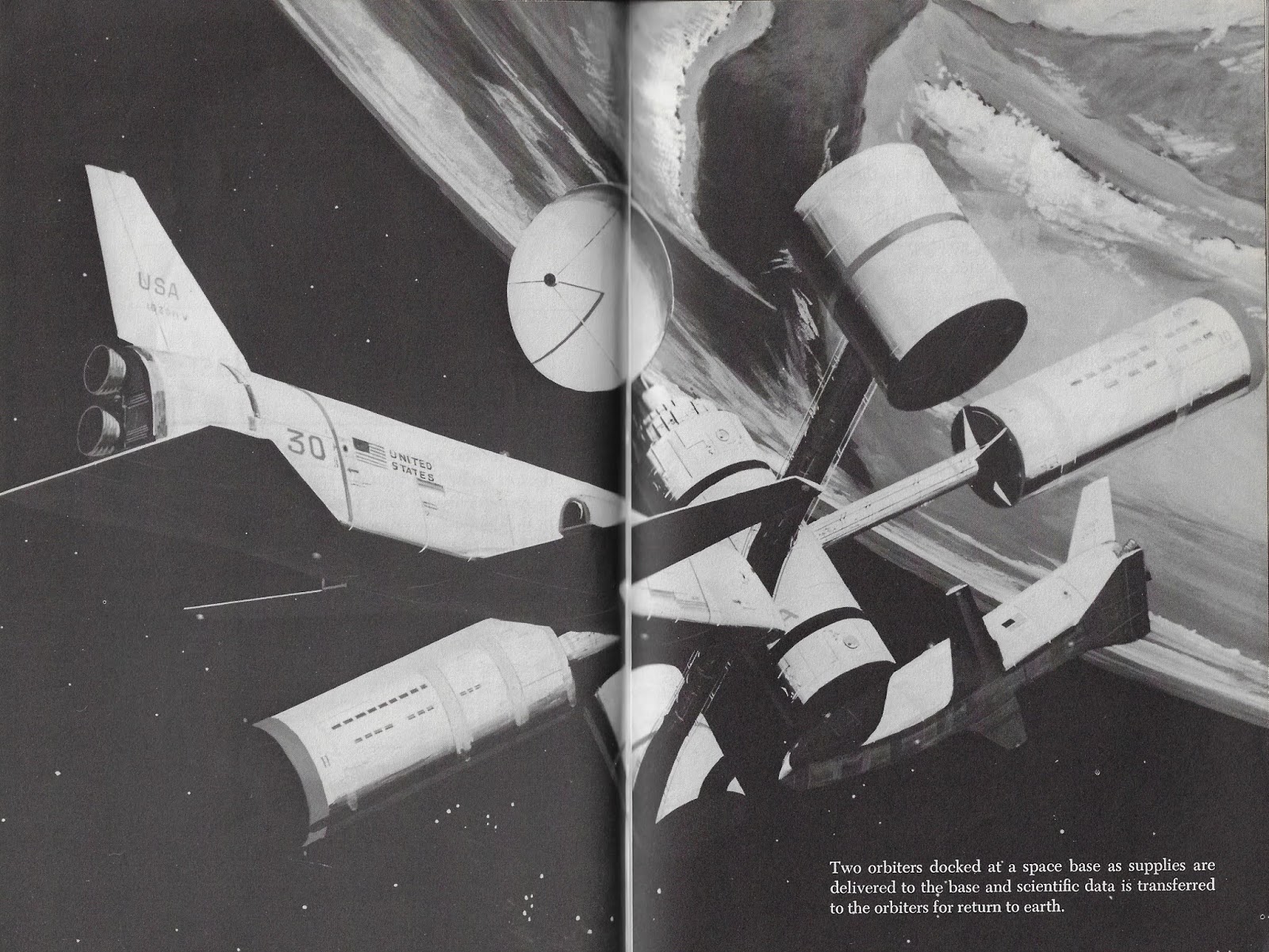
Credit: John Sisson/Dreams of Space - Books and Ephemera blogspot
And:
forum.kerbalspaceprogram.com/index.php?/topic/127839-maxi...
Credit: KERBAL SPACE PROGRAM website/LOTS of cool stuff at this website as well.
en.wikipedia.org/wiki/North_American_DC-3
Credit Wikipedia
Dès sa construction, l'abbaye fut une des plus importantes de l'Ordre cistercien, filiale de l'abbaye de Santes Creus dans la Province de Tarragone. Toute la Valldigna (vallée digne) était propriété de cette communauté monacale par ordre royal. Son style de construction est gothique valencien.
L'abbaye fut habitée par les moines jusqu'en 1835, où une révolte populaire dans la Valldigna après le désamortissement de Mendizábal (confiscation d'une partie des biens du clergé) obligea les moines à abandonner le monastère. La majeure partie de ses biens furent détruits ou spoliés.
théatre italien
Le teatrino siciliano du XVIIIème siècle provenant du Palais Butera en Sicile, fut transporté à Paris par son ancien propriétaire, Piero Lanza di Banciforte e di Butera, Duc de Camastra, qui s'installa à Paris au début du XXème siècle à la suite de son mariage avec Rose-Blache Ney d'Elschingen, descendante du Maréchal de Napoléon.
En 1937, le décor fut installé, avec quelques remaniements et ajouts, par un spécialiste de l'art vénitien du XVIIIème siècle, l'architecte décorateur Adolphe Loewi.
Partout des oiseaux et toutes sortes de personnages occupent les panneaux semés de fleurs
Des figures de l'Allégorie, de la Mythologie et de la Commedia del Arte se côtoient, dans un effet d'ensemble imaginatif et exotique, reflétant le goût du XVIIIème siècle.
Sur la voussure en bois sculpé garni de miroirs, des Amours, volant dans les airs, tiennent des guirlandes.
Le plafond est décoré de motifs de stuc, de fleurs et feuilles en tôle, imités de ceux de l'ancien hôpital de Palerme.
Les grands lustres et les appliques proviennet d'un palais de Pola, contemporain de l'impératrice Marie-Thérèse (1717-1780)
Đây là những giây fút mà 2 đứa tui hại não nhau đó mà,2 đứa thức tới sáng mà nói 2 đứa dị chớ có 1 mình t thức à Băng ưiiiiii,m khò trc t nữa m :)) Tao thức t show pic mà đầy bộ nhớ lun ó =)).Điz,2 con điên vl =)) Má nhớ lại bật tivi mà âm thanh nó tưng bừng như mưa dị á má :)) Đéo nhịn cừi nổi lun.kaka.Xĩn dô trợt cái miếng thảm té 1 cái như là bịch mũi.á haha =)) Điên gì mà điên dữ dị trừiiiiii ưiiii :)) Cười lăn loàng,té cả võng lunnn.Muahhahhahha =))>:):x Mà vui gê í :"> ngũ vs m tao đở buồn.Mà sáng m đi Campuchia m bỏ t bò lê lết dị má =)) Làm con ông Giang lun.muahaha :x :"> Híhí 2 đứa nấu phở ăn.m ăn phở t ăn kemmmm :)) Quậy vl =)) hihihehehuhuhahahohohôhôhêhê >:)❌*:) Sẽ có dịp ngũ chug vs bánh bèo hại não nữaaaaaa :x🅿️">
Bonus Hại nảo lắm nha hơmmmm nhiều thiệt nhìuuuuuu =)) Thấy cưng thấy ớn =)) kaka
Expo BOLDINI au Petit Palais...une pure merveille !!! - 8
Difficile de dissocier pour moi l’amour de la photographie de celui de la peinture. Les deux techniques nous renvoient souvent vers un miroir de l’âme. Les plaisirs émotionnels sont proches; entre apprécier un magnifique portrait photographique et découvrir le tableau d’un grand peintre. On est frappé par la beauté de la réalisation et de la technique, par toute la palette de sentiments, d’émotions de beauté, de vie qu’un artiste est capable de faire naître avec simplement quelques pigments jetés ou posés selon la maîtrise de son Art.
BOLDINI, dans son Art fût à n’en pas douter un très grand maître…Permettez que j’essaye de vous faire partager le plaisir que j’ai à admirer ses œuvres.
Le Pont du Millenium (en anglais : Millennium Bridge) est un pont suspendu situé à Londres au Royaume-Uni. Il s'agit d'une passerelle en acier réservée aux piétons enjambant la Tamise pour relier le quartier de Southwark sur la rive gauche à la City de l'autre côté. Le pont se trouve entre le Southwark Bridge en aval et le Blackfriars Bridge en amont. Inauguré le 10 juin 2000, il était le premier pont construit à Londres depuis le Southwark Bridge inauguré en 1921.
Le Millenium Bridge permet de se rendre au théâtre du Globe, à la Bankside Gallery et à la Tate Modern sur la rive gauche, ainsi qu'à la City of London School et la cathédrale Saint-Paul sur la rive droite.
L'alignement du pont est tel que la façade sud de la cathédrale Saint-Paul, encadrée par les portants du pont, est visible de l'autre côté du fleuve, offrant ainsi une des plus belles vues de la cathédrale. Il est créé par Norman Foster.
La conception du pont a fait l'objet d'un concours organisé en 1996 par le Conseil Municipal de Southwark. Le gagnant du concours fut un projet novateur intitulé Lame de Lumière réalisé par Arup, Foster et associés et Sir Anthony Caro.
En raison des limitations en hauteur et aussi pour améliorer la vue, les câbles de suspension ont été tendus au-dessous du niveau de la plate-forme, donnant ainsi un profil très peu profond. Le pont repose sur deux piliers enfoncés dans le fleuve ; il est constitué de trois sections principales de 81 m, 144 m et 108 m (du nord au sud), avec une structure d'une longueur totale de 325 mètres. La plate-forme en aluminium a une largeur de 4 mètres. Huit câbles de suspension exercent une poussée de 2 000 tonnes sur les piliers implantés sur chaque rive, suffisants pour soutenir une charge de 5 000 personnes.
Wobbly Bridge : 4m de largeur pour 320 de longueur. Les travaux ont commencé fin 1998 et la construction proprement dite, par Monberg Thorsen et Sir Robert McAlpine, le 28 avril 1999. Le pont a été inauguré le 10 juin 2000, avec deux mois de retard et un supplément de 2,2 millions de livres sur un budget initial de 18,2 millions de livres.
Cependant il a dû être fermé au public deux jours plus tard, en raison d'un phénomène de résonance, le pont oscillant latéralement de façon imprévue. Ce jour-là, une marche caritative devant traverser le pont attira beaucoup de monde. Les mouvements de balancement furent provoqués par le grand nombre de piétons (90 000 personnes le premier jour avec jusqu'à 2 000 personnes en même temps sur le pont). Les premières vibrations encourageaient et parfois obligeaient les piétons à marcher au rythme du balancement, ce qui accentua les oscillations, même en début de journée lorsque le pont était relativement peu chargé.
Ce mouvement de balancement lui a valu le surnom de Wobbly Bridge (pont bancal). Les mesures prises pour limiter le nombre de personnes traversant le pont ont entraîné de longues files d'attente, mais n'ont atténué ni l'enthousiasme du public pour ce manège qui décoiffe, ni les vibrations elles-mêmes. La fermeture du pont après seulement trois jours d'ouverture a été sévèrement critiquée par le public, qui associait ce retard à celui dont avait souffert le Dôme du Millenium.
Les phénomènes de résonance des ponts suspendus avaient été bien étudiés depuis la catastrophe du pont de Tacoma Narrows (Washington, États-Unis). Néanmoins peu d'attention avait été prêtée au mouvement latéral produit par des piétons, provoqué par la réaction humaine à des petits mouvements latéraux dans le pont, entraînant un mouvement de pulsion qui n'avait pas été anticipé dans l'analyse statistique avant la construction. On a pensé que le profil exceptionnellement bas des câbles de suspension a contribué au problème, mais une étude menée par des ingénieurs prouve que l'oscillation peut se produire sur n'importe quel pont à suspension ou autre, soumis à un grand mouvement de foule.
Le problème a été résolu par l'installation d'amortisseurs hydrauliques et de masse pour contrôler les oscillations horizontales et latérales. Les travaux ont été menés de mai 2001 à janvier 2002. Après une période d'essai, le pont a été rouvert au public le 22 février 2002 : depuis, aucune vibration importante n'a été signalée.
Le 18 janvier 2007 le pont fut une nouvelle fois fermé, mais cette fois en raison des vents violents provoqués par la Tempête Kyrill et qui menaçaient d'emporter les piétons.
Dans le film Harry Potter et le Prince de Sang-Mêlé de David Yates sorti le 15 juillet 2009 au cinéma, le Millennium Bridge est attaqué et détruit par des Mangemorts. Cependant, c'est une erreur de la part des producteurs car l'attaque est censée avoir lieu en 1996, alors que le pont n'a été ouvert qu'en 2000.
Dans le film Rubinrot de Felix Fuchssteiner sorti le 14 mars 2013 au cinéma, Gwendolyn téléphone à son amie Leslie depuis le Millennium Bridge pour lui confier qu'elle a fait un voyage dans le temps.
--------------------------------------
The Millennium Bridge, officially known as the London Millennium Footbridge, is a steel suspension bridge for pedestrians crossing the River Thames in London, linking Bankside with the City of London. It is sited between Southwark Bridge and Blackfriars Railway Bridge. The Millennium Bridge is owned and maintained by Bridge House Estates, a charitable trust overseen by the City of London Corporation. Construction of the bridge began in 1998, with the opening in June 2000.
Londoners nicknamed the bridge the "Wobbly Bridge" after participants in a charity walk on behalf of Save the Children to open the bridge felt an unexpected and, for some, uncomfortable swaying motion on the first two days after the bridge opened. The bridge was closed later that day, and after two days of limited access the bridge was closed for almost two years while modifications were made to eliminate the wobble entirely. It reopened in 2002.
The southern end of the bridge is near the Globe theatre, the Bankside Gallery and Tate Modern, the north end next to the City of London School below St Paul's Cathedral. The bridge alignment is such that a clear view of St Paul's south façade is presented from across the river, framed by the bridge supports.
The design of the bridge was the subject of a competition organized in 1996 by Southwark council and RIBA Competitions. The winning entry was an innovative "blade of light" effort from Arup, Foster and Partners and Sir Anthony Caro. Due to height restrictions, and to improve the view, the bridge's suspension design had the supporting cables below the deck level, giving a very shallow profile. The bridge has two river piers and is made of three main sections of 81 metres (266 ft), 144 metres (472 ft) and 108 metres (354 ft) (North to South) with a total structure length of 325 metres (1,066 ft); the aluminium deck is 4 metres (13 ft) wide. The eight suspension cables are tensioned to pull with a force of 2,000 tons against the piers set into each bank — enough to support a working load of 5,000 people on the bridge at one time.
Ordinarily bridges across the River Thames require an Act of Parliament. For this bridge that was avoided by the Port of London Authority granting a licence for the structure obtaining planning permissions from the City of London and London Borough of Southwark. Construction began in late 1998 and the main works were started on 28 April 1999 by Monberg & Thorsen and Sir Robert McAlpine. The bridge was completed at a cost of £18.2M (£2.2M over budget), primarily paid for by the Millennium Commission and the London Bridge Trust. It opened on 10 June 2000 (two months late).
Unexpected lateral vibration (resonant structural response) caused the bridge to be closed on 12 June 2000 for modifications. Attempts were made to limit the number of people crossing the bridge. This led to long queues and dampened neither public enthusiasm for what was something of a white-knuckle ride, nor the vibrations themselves. The closure of the bridge only two days after opening attracted public criticism of it as another high-profile British Millennium project suffered an embarrassing setback, akin to how many saw the Millennium Dome. The wobble was attributed to an under-researched phenomenon whereby pedestrians crossing a bridge that has a lateral sway have an unconscious tendency to match their footsteps to the sway, thereby exacerbating the sway. The tendency of a suspension bridge to sway when troops march over it in step was well known, which is why troops are required to break step when crossing such a bridge.
The bridge was temporarily closed on 18 January 2007, during the Kyrill storm due to strong winds and a risk of pedestrians being blown off the bridge.
The bridge's movements were caused by a 'positive feedback' phenomenon, known as synchronous lateral excitation. The natural sway motion of people walking caused small sideways oscillations in the bridge, which in turn caused people on the bridge to sway in step, increasing the amplitude of the bridge oscillations and continually reinforcing the effect. On the day of opening the bridge was crossed by 90,000 people, with up to 2,000 on the bridge at any one time.
Resonant vibrational modes due to vertical loads (such as trains, traffic, pedestrians) and wind loads are well understood in bridge design. In the case of the Millennium Bridge, because the lateral motion caused the pedestrians loading the bridge to directly participate with the bridge, the vibrational modes had not been anticipated by the designers. The crucial point is that when the bridge lurches to one side, the pedestrians must adjust to keep from falling over, and they all do this at exactly the same time. Hence the situation is similar to soldiers marching in lockstep, but horizontal instead of vertical.
The lateral vibration problems of the Millennium Bridge are very unusual, but not entirely unique. Any bridge with lateral frequency modes of less than 1.3 Hz, and sufficiently low mass, could witness the same phenomenon with sufficient pedestrian loading. The greater the number of people, the greater the amplitude of the vibrations. For example, Albert Bridge in London has a sign dating from 1873 warning marching ranks of soldiers to break step while crossing. Other bridges which have seen similar problems are:
•Birmingham NEC Link bridge, with a lateral frequency of 0.7 Hz
•Groves Suspension Bridge, Chester, in 1977 during the Jubilee river regatta
•Auckland Harbour Road Bridge, with a lateral frequency of 0.67 Hz, during a 1975 demonstration
After extensive analysis by the engineers, the problem was fixed by the retrofitting of 37 fluid-viscous dampers (energy dissipating) to control horizontal movement and 52 tuned mass dampers (inertial) to control vertical movement. This took from May 2001 to January 2002 and cost £5M. After a period of testing, the bridge was successfully re-opened on 22 February 2002. The bridge has not been subject to significant vibration since. In spite of the successful fix of the problem, the affectionate "wobbly bridge" epithet remains in common usage among Londoners.
An artistic expression of the higher-frequency resonances within the cables of the bridge were explored by Bill Fontana's 'Harmonic Bridge' exhibition at the Tate Modern museum in mid-2006. This used acoustic transducers placed at strategic locations on the cabling of the Millennium Bridge and the signals from those transducers were amplified and dynamically distributed throughout the Turbine Hall of the Tate by a programme which Fontana entered into the sound diffusion engine of the Richmond Sound Design AudioBox.
•The Millennium Bridge was featured in the sixth installment of the Harry Potter film franchise, where the bridge collapsed following an attack by Death Eaters.
•The Bridge also appeared in the 2014 Marvel Cinematic Universe film Guardians of the Galaxy during the climactic battle on Xandar.
•The Bridge also appeared in the video to the Olly Murs song "Heart on My Sleeve."
--------------------------------------
El Puente del Milenio es un puente colgante, peatonal y fabricado con acero que cruza el río Támesis, a su paso por Londres, en Inglaterra, uniendo la zona de Bankside con la City. Se localiza entre el Puente de Southwark y el Puente de Blackfriars. Fue el primero que cruzó el Támesis desde que se construyera el Tower Bridge, o Puente de la Torre, en 1894. Es propiedad de la Bridge House Estates una fundación benéfica que también se encarga de su mantenimiento, y que es supervisada por la City of London Corporation.
El lado sur del puente se encuentra cerca del teatro The Globe, de la Galería de Bankside y del Tate Modern. El lado norte del puente se encuentra cerca de la School of London City y de la Catedral de San Pablo. El alineamiento del puente es tal, que nos ofrece una clara vista de la fachada sur de la Catedral de San Pablo, enmarcada por los soportes del puente, que constituye uno de los lugares mas fotogénicos de la Catedral.
El diseño del puente fue elegido por concurso, en 1996 por el concilio de Southwark. El diseño ganador fue muy innovador, y fue realizado por Arup, por Foster and Partners y por sir Anthony Caro. Debido a las restricciones de peso, y para mejorar la vista, la suspensión del puente tuvo que tener cables de apoyo bajo el nivel de la cubierta, dando una sensación de poca profundidad en las aguas. El puente tiene dos plataformas de soporte y está hecho en tres secciones de 81 m, 144 m, y 108 m (de norte a sur) con una estructura resultante de 325 m; la cubierta de aluminio mide 4 m de ancho. Los 8 cables que mantienen el puente en suspensión, están tensados para poder sostener 2000 toneladas de peso, lo suficiente para soportar a 5000 personas en el puente al mismo tiempo.
La construcción comenzó a finales de 1998, pero los principales trabajos comenzaron el 28 de abril de 1999. El coste económico del puente fue de 18,2 millones de Libras, 2,2 millones por encima del presupuesto anunciado. Fue abierto el 10 de junio del año 2000, dos meses más tarde de lo esperado, y unas inesperadas vibraciones y fallos estructurales, hicieron que éste tuviera que ser cerrado el 12 de junio, dos días después de su apertura, para realizar modificaciones. Estos movimientos eran producidos por el gran número de personas, 90.000 el primer día y más de 2.000 en el puente al mismo tiempo. Las primeras pequeñas vibraciones animaron (o incluso obligaron) a los viandantes a caminar de manera sincronizada con el balanceo, incrementando el efecto, incluso cuando el puente se encontraba relativamente poco transitado al comienzo del día. Estos balanceos hicieron que el puente se ganase el apodo de Wobbly Bridge.
Se intentó limitar el número de personas cruzando el puente en el mismo momento. La clausura del puente solo 3 días después de que se abriese produjo una gran crítica pública, como otro gran proyecto del sentir británico que sufría un revés vergonzoso, semejante al del Millennium Dome.
Tras unas obras que duraron desde mayo de 2001 hasta enero de 2002 y que costaron 5 millones de libras, el problema se arregló, y tras un periodo de prueba, se reabrió el 22 de febrero de 2002.
Desde entonces no se han vuelto a tener noticias de movimientos extraños en el puente, y sólo se volvió a cerrar durante la tormenta Kyrill, una especie de ciclón.
Original 1958-60 artist’s concept of Boeing Aircraft Company’s bold Program for Astronomical Research and Scientific Experiments Concerning Space (PARSECS) concept/proposal. Within PARSECS, this specifically depicts “Mission II: Moon Base”.
The least detailed mission within the proposal, an unspecified paper states that the image depicts the original concept of the lunar base as envisioned in 1958.
My above paraphrasing is from the excellent discussion and particularly, the contribution of user “Skybolt”, at:
www.secretprojects.co.uk/threads/parsecs-1960.7039/
Credit: SECRET PROJECTS website
Although most of the stunning PARSECS renditions are by the eminently talented Robert Fetterly, I don’t know if this is by his hand.
Regardless, Rest In Peace and thank you for your service:
www.peninsuladailynews.com/news/back-to-the-future-artist...
Credit: Peninsula Daily News website
That’s a LOT of communications/radar? antennas & dishes. And those are some seriously funky looking tri-wheeled ‘rovers’ parked to the lower right.
“UNMANNED MARS VISIT ARTWORK —- Art concept
depicting unmanned exploration of Mars, considered
as a possible precursor to a manned exploration of Mars in the next century. A study at the Jet Propulsion Laboratory lead to a series of art concepts depicting scenarios considered.
pg. 41-3”
Above is per the caption associated with the black & white version of the photo.
Possibly an evolution of JPL’s original “Purple Pigeon” concept/proposal, depicting a Mars Surface Sample Return (MSSR) mission.
In lieu of any other imagery, I refer to this as a possible extension of the Mars Purple Pigeon proposal simply because Mr. Portree alludes to such in referencing an image with similar rovers:
spaceflighthistory.blogspot.com/2018/12/dual-mars-rovers-...
Credit: “No Shortage of Dreams: Mars Multi-Rover Mission (1977)”/David S. F. Portree
One of so many wonderful works for JPL by Ken Hodges.
However, for whatever it's worth, the official caption of a companion?/associated? photo (JPL photo no. P-17055AC) makes absolutely no mention of a sample return intent/capability.
Frankly, the multiple JPL 1970s proposals for Mars exploration during the 1980s & beyond, are rather confusing & convoluted. At least to me.