View allAll Photos Tagged published
...for an unknown person that suffers from leukemia.
A bag full of blood stem cells for a Hematopoietic stem cell transplantation (bone marrow).
The donation is anonymous,
I do not know who's gonna get it - the recipient does not know who I am.
Maybe I will be informed if everything went okay... we will have to wait for X-mas...
Two weeks after my donation of stem cells (bone marrow) I am still doing very well
see details here (preparations) and here (donation).
Today I received a little 'thank-you'-box from the centre that coordinates all the bone marrow donations for western Germany (http://www.wsze.de") and an additionall address that I did not know yet.
This is for all the american friends out there!
Yep, for informational purposes for everybody in the Americas: south, latin and US/CN.
Take a look at the web site of the NATIONAL MARROW DONOR PROGRAM™:
Information is also available in other languages
www.marrow.org/TRANSLATIONS/SPANISH/index.html
www.marrow.org/TRANSLATIONS/CHINESE/index.html
www.marrow.org/TRANSLATIONS/KOREAN/index.html
www.marrow.org/TRANSLATIONS/VIETNAMESE/index.html
www.marrow.org/TRANSLATIONS/TAGALOG/index.html (yes Phillippines!)
PLEASE LOOK AT THIS:
www.jonahchuang.com/dnn/Home/tabid/36/Default.aspx
Feel free to share this,
the more people know about it, the more may help to save a life!
Spread the news...
veröffentlicht auf / published on
This little booklet, written by Gill, was published by Faber but printed at Gill & Hague's press in High Wycombe, Buckinghamshire.
This photo is published under Creative Commons Attribution-Share-Alike Licence, means you are free to use this photo with attribution under same licence. When giving attribution, please use following;
Owner: Thai National Parks
Link: www.thainationalparks.com/khao-yai-national-park/guided-tours
Published in January 1894 by The Historical Publishing Company, author J. W. Buel, this book contains 300 photographs of every aspect of the fair.
The World's Fair: Columbian Exposition (also known as the Chicago World's Fair) was a world's fair held in Chicago in 1893 to celebrate the 400th anniversary of Christopher Columbus' arrival in the New World in 1492. At the core of the fair was an area that quickly became known as the White City for its buildings with white stucco siding and its streets illuminated by electric lights.
© sergione infuso - all rights reserved
follow me on www.sergione.info
You may not modify, publish or use any files on
this page without written permission and consent.
-----------------------------
Davide, Enrica, Giosada e gli Urban Strangers, i quattro finalisti di #XF9, in diretta dal Mediolanum Forum di Assago, Milano, giovedì 10 Dicembre 2015, avranno l’onore di condividere lo stesso palco con giganti della musica come i Coldplay, in vetta alle classifiche in 53 paesi. Chris Martin & Co si esibiranno live in esclusiva per l’Italia proprio sul palco della Finale per regalare al pubblico ben due successi del nuovo album: "A Head Full of Dreams" e "Adventure of a Lifetime".
X Factor Italia vuole siglare un altro primato: l’intera giuria si esibirà sulle note dei propri successi e con le proprie band: Elio e le Storie Tese, Skunk Anansie e Fedez e Mika.
Alessandro Cattelan vi racconterà questo grandissimo evento musicale scandendo i ritmi di una serata che si preannuncia veramente intensa. Avrete modo di assistere a una sfida davvero speciale tra Enrica, Davide, Giosada e Urban Strangers al fianco di un grande artista italiano: Cesare Cremonini. Dopo 34 date del Logico Tour, la pop star bolognese accompagnerà al pianoforte i ragazzi nella prima manche dedicata ai duetti, al termine della quale uno di loro lascerà la gara, oltre ad eseguire "Lost in weekend".
La sfida proseguirà con la manche degli inediti, appena presentati e già in cima alla classifica iTunes. Per lo scontro decisivo, i due super finalisti si giocheranno il podio con un brano scelto da ciascuno di loro tra quelli interpretati durante il lungo percorso ad X Factor. Solo uno di loro si aggiudicherà un contratto con Sony Music Italia e la possibilità di pubblicare un album.
Non finisce qui: un inedito duetto infiammerà il Forum, quello di Fedez & Mika, che si esibiranno per la prima volta live nel loro "Beautiful Disaster". Elio e le Storie Tese si porteranno al Forum uno dei classici storici della band, "Servi della gleba", mentre gli Skunk Anansie la nuovissima "Love Someone Else".
Il vincitore della nona edizione di X Factor Italia è Giosada.
Thanks to www.flickr.com/photos/michaelbarnes/ for the cover preview.
Photosho is a new All Canadian content independent Magazine put together by Mike and Rachel Barnes thanks guys for choosing my photo .
For more info on the magazine Here is there flickr group www.flickr.com/groups/photosho/ and the magazines web site www.photosho.ca/issue1.html
Rapid strata formation in soft sand (field evidence).
Photo of strata formation in soft sand on a beach, created by tidal action of the sea.
Formed in a single, high tidal event. Stunning evidence which displays multiple strata/layers.
Why this is so important ....
It has long been assumed, ever since the 17th century, that layers/strata observed in sedimentary rocks were built up gradually, layer upon layer, over many years. It certainly seemed logical at the time, from just looking at rocks, that lower layers would always be older than the layers above them, i.e. that lower layers were always laid down first followed, in time, by successive layers on top.
This was assumed to be true and became known as the superposition principle.
It was also assumed that a layer comprising a different material from a previous layer, represented a change in environmental conditions/factors.
These changes in composition of layers or strata were considered to represent different, geological eras on a global scale, spanning millions of years. This formed the basis for the Geologic Column, which is used to date rocks and also fossils. The evolutionary, 'fossil record' was based on the vast ages and assumed geological eras of the Geologic Column.
There was also circular reasoning applied with the assumed age of 'index' fossils (based on evolutionary beliefs & preconceptions) used to date strata in the Geologic Column. Dating strata from the assumed age of (index) fossils is known as Biostratigraphy.
We now know that, although these assumptions seemed logical, they are not supported by the evidence.
At the time, the mechanics of stratification were not properly known or studied.
An additional factor was that this assumed superposition and uniformitarian model became essential, with the wide acceptance of Darwinism, for the long ages required for progressive microbes-to-human evolution. There was no incentive to question or challenge the superposition, uniformitarian model, because the presumed, fossil 'record' had become dependant on it, and any change in the accepted model would present devastating implications for Darwinism.
This had the unfortunate effect of linking the study of geology so closely to Darwinism, that any study independent of Darwinian considerations was effectively stymied. This link of geology with Darwinian preconceptions is known as biostratigraphy.
Some other field evidence, in various situations, can be observed here: www.flickr.com/photos/101536517@N06/sets/72157635944904973/
and also in the links to stunning, experimental evidence, carried out by sedimentologists, given later.
_______________________________________________
GEOLOGIC PRINCIPLES (established by Nicholas Steno in the 17th Century):
What Nicolas Steno believed about strata formation is the basis of the principle of Superposition and the principle of Original Horizontality.
dictionary.sensagent.com/Law_of_superposition/en-en/
“Assuming that all rocks and minerals had once been fluid, Nicolas Steno reasoned that rock strata were formed when particles in a fluid such as water fell to the bottom. This process would leave horizontal layers. Thus Steno's principle of original horizontality states that rock layers form in the horizontal position, and any deviations from this horizontal position are due to the rocks being disturbed later.”)
BEDDING PLANES.
'Bedding plane' describes the surface in between each stratum which are formed during sediment deposition.
science.jrank.org/pages/6533/Strata.html
“Strata form during sediment deposition, that is, the laying down of sediment. Meanwhile, if a change in current speed or sediment grain size occurs or perhaps the sediment supply is cut off, a bedding plane forms. Bedding planes are surfaces that separate one stratum from another. Bedding planes can also form when the upper part of a sediment layer is eroded away before the next episode of deposition. Strata separated by a bedding plane may have different grain sizes, grain compositions, or colours. Sometimes these other traits are better indicators of stratification as bedding planes may be very subtle.”
______________________________________________
Several catastrophic events, flash floods, volcanic eruptions etc. have forced Darwinian, influenced geologists to admit to rapid stratification in some instances. However they claim it is a rare phenomenon, which they have known about for many years, and which does nothing to invalidate the Geologic Column, the fossil record, evolutionary timescale, or any of the old assumptions regarding strata formation, sedimentation and the superposition principle. They fail to face up to the fact that rapid stratification is not an extraordinary phenonemon, but rather the prevailing and normal mechanism of sedimentary deposition whenever and wherever there is moving, sediment-laden water. The experimental evidence demonstrates the mechanism and a mass of field evidence in normal (non-catastrophic) conditions shows it is a normal everyday occurrence.
It is clear from the experimental evidence that the usual process of stratification is - that strata are not formed by horizontal layers being laid on top of each other in succession, as was assumed. But by sediment being sorted in the flowing water and laid down diagonally in the direction of flow. See diagram:
www.flickr.com/photos/truth-in-science/39821536092/in/dat...
The field evidence (in the image) presented here - of rapid, simultaneous stratification refutes the Superposition Principle and the Principle of Lateral Continuity.
We now know, the Superposition Principle only applies on a rare occasion where sedimentary deposits are laid down in still water.
Superposition is required for the long evolutionary timescale, but the evidence shows it is not the general rule, as was once believed. Most sediment is laid down in moving water, where particle segregation is the general rule, resulting in the simultaneous deposition of strata/layers as shown in the photo.
See many other examples of rapid stratification (with geological features): www.flickr.com/photos/101536517@N06/sets/72157635944904973/
Rapid, simultaneous formation of layers/strata, through particle segregation in moving water, is so easily created it has even been described by sedimentologists (working on flume experiments) as a law ...
"Upon filling the tank with water and pouring in sediments, we immediately saw what was to become the rule: The sediments sorted themselves out in very clear layers. This became so common that by the end of two weeks, we jokingly referred to Andrew's law as "It's difficult not to make layers," and Clark's law as "It's easy to make layers." Later on, I proposed the "law" that liquefaction destroys layers, as much to my surprise as that was." Ian Juby, www.ianjuby.org/sedimentation/
The example in the photo is the result of normal, everyday tidal action formed in a single incident, and subsequently eroded by water flow revealing the strata/layers.
Where the water current or movement is more turbulent, violent, or catastrophic, great depths (many metres) of stratified sediment can be laid down in a short time. Certainly not the many millions of years assumed by evolutionists.
The composition of strata formed in any deposition event. is related to whatever materials are in the sediment mix, not to any particular timescale. Whatever is in the mix will be automatically sorted into strata/layers. It could be sand, or other material added from mud slides, erosion of chalk deposits, coastal erosion, volcanic ash etc. Any organic material (potential fossils), alive or dead, engulfed by, or swept into, a turbulent sediment mix, will also be sorted and buried within the rapidly, forming layers.
See many other examples of rapid stratification with geological features: www.flickr.com/photos/101536517@N06/sets/72157635944904973/
Stratified, soft sand deposit. demonstrates the rapid, stratification principle.
Important, field evidence which supports the work of the eminent, sedimentologist Dr Guy Berthault MIAS - Member of the International Association of Sedimentologists.
(Dr Berthault's experiments (www.sedimentology.fr/)
And also the experimental work of Dr M.E. Clark (Professor Emeritus, U of Illinois @ Urbana), Andrew Rodenbeck and Dr. Henry Voss, (www.ianjuby.org/sedimentation/)
Location: Yaverland, Isle of Wight. Photographed 12/10/2018 This field evidence demonstrates that multiple strata in sedimentary deposits do not need millions of years to form and can be formed rapidly. This natural example confirms the principle demonstrated by the sedimentation experiments carried out by Dr Guy Berthault and other sedimentologists. It calls into question the standard, multi-million year dating of sedimentary rocks, and the dating of fossils by depth of burial or position in the strata.
Mulltiple strata/layers are evident in this example.
Dr Berthault's experiments (www.sedimentology.fr/) and other experiments (www.ianjuby.org/sedimentation/) and field studies of floods and volcanic action show that, rather than being formed by gradual, slow deposition of sucessive layers superimposed upon previous layers, with the strata or layers representing a particular timescale, particle segregation in moving water or airborne particles can form strata or layers very quickly, frequently, in a single event.
And, most importantly, lower strata are not older than upper strata, they are the same age, having been created in the same sedimentary episode.
Such field studies confirm experiments which have shown that there is no longer any reason to conclude that strata/layers in sedimentary rocks relate to different geological eras and/or a multi-million year timescale. www.youtube.com/watch?v=5PVnBaqqQw8&feature=share&.... they also show that the relative position of fossils in rocks is not indicative of an order of evolutionary succession. Obviously, the uniformitarian principle, on which the geologic column is based, can no longer be considered valid. And the multi-million, year dating of sedimentary rocks and fossils needs to be reassessed. Rapid deposition of stratified sediments also explains the enigma of polystrate fossils, i.e. large fossils that intersect several strata. In some cases, tree trunk fossils are found which intersect the strata of sedimentary rock up to forty feet in depth. upload.wikimedia.org/wikipedia/commons/thumb/0/08/Lycopsi... They must have been buried in stratified sediment in a short time (certainly not millions, thousands, or even hundreds of years), or they would have rotted away. youtu.be/vnzHU9VsliQ
In fact, the vast majority of fossils are found in good, intact condition, which is testament to their rapid burial. You don't get good fossils from gradual burial, because they would be damaged or destroyed by decay, predation or erosion. The existence of so many fossils in sedimentary rock on a global scale is stunning evidence for the rapid depostion of sedimentary rock as the general rule. It is obvious that all rock containing good intact fossils was formed from sediment laid down in a very short time, not millions, or even thousands of years.
See set of photos of other examples of rapid stratification: www.flickr.com/photos/101536517@N06/sets/72157635944904973/
Carbon dating of coal should not be possible if it is millions of years old, yet significant amounts of Carbon 14 have been detected in coal and other fossil material, which indicates that it is less than 50,000 years old. www.ldolphin.org/sewell/c14dating.html
www.grisda.org/origins/51006.htm
Evolutionists confidently cite multi-million year ages for rocks and fossils, but what most people don't realise is that no one actually knows the age of sedimentary rocks or the fossils found within them. So how are evolutionists so sure of the ages they so confidently quote? The astonishing thing is they aren't. Sedimentary rocks cannot be dated by radiometric methods*, and fossils can only be dated to less than 50,000 years with Carbon 14 dating. The method evolutionists use is based entirely on assumptions. Unbelievably, fossils are dated by the assumed age of rocks, and rocks are dated by the assumed age of fossils, that's right ... it is known as circular reasoning.
* Regarding the radiometric dating of igneous rocks, which is claimed to be relevant to the dating of sedimentary rocks, in an occasional instance there is an igneous intrusion associated with a sedimentary deposit -
Prof. Aubouin says in his Précis de Géologie: "Each radioactive element disintegrates in a characteristic and constant manner, which depends neither on the physical state (no variation with pressure or temperature or any other external constraint) nor on the chemical state (identical for an oxide or a phosphate)."
"Rocks form when magma crystallizes. Crystallisation depends on pressure and temperature, from which radioactivity is independent. So, there is no relationship between radioactivity and crystallisation.
Consequently, radioactivity doesn't date the formation of rocks. Moreover, daughter elements contained in rocks result mainly from radioactivity in magma where gravity separates the heavier parent element, from the lighter daughter element. Thus radiometric dating has no chronological signification." Dr. Guy Berthault www.sciencevsevolution.org/Berthault.htm
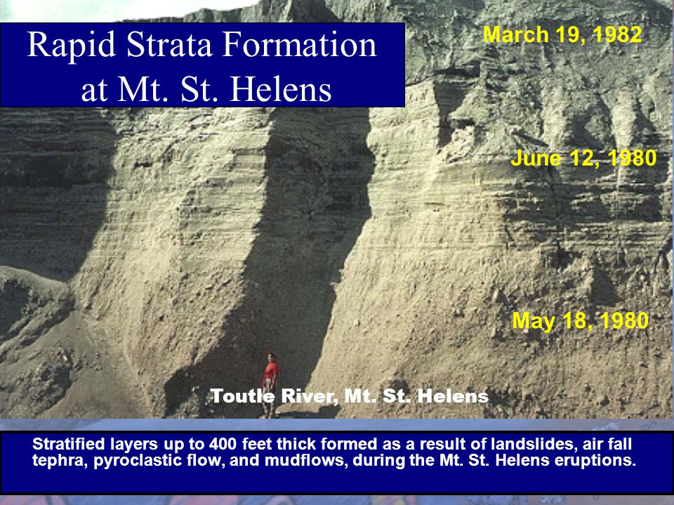
Rapid strata formation and rapid erosion at Mount St Helens.
slideplayer.com/slide/5703217/18/images/28/Rapid+Strata+F...
Visit the fossil museum:
www.flickr.com/photos/101536517@N06/sets/72157641367196613/
Just how good are peer reviews of scientific papers?
www.sciencemag.org/content/342/6154/60.full
www.examiner.com/article/want-to-publish-science-paper-ju...
The neo-Darwinian idea that the human genome consists entirely of an accumulation of billions of mutations is, quite obviously, completely bonkers. Nevertheless, it is compulsorily taught in schools and universities as 'science'.
Published in :
1. POTD in www.photographyvoice.com dated 3rd August '2011
2. Asian Photography and Imaging magazine. Issue : September '2011
Three of my photos are in the Alaska Pocket Wildlife Guide available at ultimaterivers.com. Nice guide with viewing tips and locations for Alaska's birds and mammals.
No need for comments...
My stocklist
Mathew Brady took this photo on March 27, 1863 and it was published as a stereoview from the Brady negative by E & H.T. Anthony around the same year. The delegation of Indians from the Southern Plains with their interpreter, John Smith, met with President Lincoln at the height of the Civil War. The purpose was to secure peaceful relations and dissuade the Indians from joining forces with the Confederacy.
Seated in the front row are, left to right – Standing in Water, War Bonnet and Lean Bear of the Cheyenne; and Yellow Wolf, Kiowa, who wears a large silver Peace Medal given to his tribe by President Thomas Jefferson. Two Indian men and two women are seated in the middle row and seven Indian men stand in the last row. In the back, obscured behind the figure of John Smith, two top hats reveal the presence of other visitors. At left, partially hidden by a potted plant is a young boy wearing a hat seen in profile regarding the Indian visitors.
Less than two years after this historic photograph, all four Indian Peace delegates seated in the front row were dead. Yellow Wolf succumbed to pneumonia days later and was buried with his Peace Medal in Congressional Cemetery. War Bonnet and Standing in Water were killed by the Colorado Territory Militia in the Sand Creek Massacre on November 29, 1864. On May 16, 1864, mistaken for a hostile, Lean Bear protested that he had “visited the home of the white Father” but fell under a volley from the same militia. [From the Journal of the White House Historical Association, Washington, D.C. November 25, 2009]
(Note: An inexpensive viewer can turn the side-by-side images on the computer screen into a 3-D image. The viewer is available from the following source:
Recently a group of artist from the DMV area got together for a shoot with model Connie Shih,the photography wasdone by international photographer Svenler.Here is a little about each of the participants in this amazing photoshot , the images that you see here are from the actual production from the shoot . a gallery link will be posted soon and we would like for you to look for some of the images to be published in Europe and the U.S.
A bit abpout the Team:
About Imaginis Photography
My name is Sven Bannuscher and I am the owner and main photographer of Imaginis Photography. I have many years of experience as a photographer and have worked as a professional photographer in Europe (France, Germany, Monaco) as well as in the United States and Canada.
My photos have been published in the Washington Post, Washington Diplomat, Austria Info, and several other national and international publications.
I started my career as a landscape and architecture photographer in Europe before moving to Bethesda, MD. This type of photography requires a high attention to detail which I still utilize today when photographing any type of assignment. No matter if it is a portrait, a wedding, a commercial advertising campaign, editorial fashion, or any other type of photography.
When photographing events such as a Wedding, I combine artistic portrait photography skills with a modern photojournalistic approach. Blending these two concepts together ensures that you will receive timeless photographs.
Business Philosophy
It has been my philosophy to combine the classic perfection of the old masters with an innovative and modern style of photography.
We offer you a package that is tailored to your needs. We make the whole process from beginning to end affordable, fun, and hassle-free. We ensure that you feel comfortable at all times and do not have to jump through any loopholes or run into any walls. You are unique and you deserve a photographer who appreciates and captures your uniqueness.
Mission Statement
To consistently create artistically notable and technically superior photographs of outstanding quality.
Shana Kroiz Jewelry:
Native Baltimorean Shana Kroiz is acknowledged as one of the country's leading experimental enamelists and jewelry educators. Throughout her career, Shana has been involved in teaching and promoting the growth of jewelry as a recognizable art form.
Shana is currently the Special Events and Workshop Coordinator of the Maryland Institute College of Art Jewelry Center, which she founded in 1992, and where she works as an instructor and studio artist. Previously, Shana was the Director of the 92nd Street Y’s Jewelry Center in NYC.
Where to see Shana's work
See Shana's work in publications
"My one-of-a-kind wearable jewelry celebrates ancient forms and the sensuous nature of the human consciousness. These pieces are universal in their appeal and personal in their effect. When worn, the jewelry interacts as sculpture making the body a pedestal."
"Rich colors are created by the primitive use of a brush stroke and layering of experimental enameling or the brilliant colors of patina on silver which reflects the history of the art."
With artistic integrity and fine craftsmanship, Kroiz captures the seduction of color and form while exploring and honoring the human spirit.
MFA,1993; Towson State University
BFA with Honors, major: Metals, minor: Clay; 1990; Parsons School of Design
One-year Intensive Metals Study, SUNY at New Paltz; 1987-1988 (with Robert Ebendorf and Jamie Bennett)
Christopher Schafer's Summary
Christopher Schafer wants you to look your best for every one of life's great occasions. He takes pride in his work and feels that every garment that he creates is a direct representation of himself. Christopher makes sure that all the details are correct and that you get the best fit possible. He will take the time with you to design the best clothing that you have ever owned. This old world work ethic is not going unnoticed, he was voted Baltimore’s Best Tailor by City Paper in 2009, Baltimore Magazine in 2010, and Fashion Awards MD in 2012.
Christopher learned that art of measuring & design to create custom clothing while living in London, a city that had a profound effect on his life. He learned from some of the best clothiers in the world and immersed himself in the English culture. Christopher would frequently visit Seville Row and Jermyn Street to gain ideas and inspiration. The end result was a new style which blends European style and fit with comfort to create clean understated lines. This formula produces fashionable, fitted and comfortable clothing that you will love to wear.
Specialties
Measuring and design of suits, shirts, formal & casual wear.
Christopher Schafer's Experience
Proprietor
Christopher Schafer Clothier (Sole Proprietorship)
Sole Proprietorship; 1-10 employees; Apparel & Fashion industry
November 2010– Present (1 year 11 months) Baltimore, Maryland Area
Measuring and design of suits, shirts, formal & casual wear.
Partner
Signature Attire
June 2011– Present (1 year 4 months) Baltimore, Maryland Area
Our ties are designed and made in America of the highest quality. Whether you seek a bespoke necktie that is subtle and elegant or bold and dramatic, each of our truly well-made ties is custom designed to set you apart from the crowd.
We know, firsthand, that if a custom necktie is eye-catching on TV, it will add distinction to your everyday life too.
President
Baltimore Fashion Alliance
September 2010– Present (2 years 1 month)Baltimore, Maryland Area
The BFA’s mission is to provide professionals in the fashion industry with superior education, networking, and resources while giving back to the community through charitable programs and contributions.
Carlous Palmer Designer /Stylist
I am an American Fashion Artist/ Stylist, with over20 years’ experience in the industry with a body of work that covers Television, Film, Stage and Fashion, I am interested in working with any one that has the drive and desire for creativity and beauty. MY GOAL IS PERFECTION. I am quick with ideas and always open to new ones THAT ARE WORKABLE
and willing to travel for fair compensation, I have worked from New York to Palm Beach in the area of retail, public relations and for one of the largest Christmas display in the country meaning that my resources are plentiful for getting things done. I am also dedicated to helping the new comer to the industry ...after all we are responsible for sharing what we know to help others to keep our art alive... feel free to contact me at carlouspalmer@yahoo.com
This year you will be seeing designs created exclusively for CHASE BREXTON HEALTH SERVICES to bring more awareness to the need to attract more people to the HIV/ AIDS crisis ... the numbers are getting higher , and I am honored to say that IKEA TEXTILES and GUSS WOOLENS have sponsored this collection and over the next few months you will be seeing designs created from IKEA TEXTILES with some designs supplemented with fabric from GUSS WOOLENS . You will be able to purchase these garments by visiting www.carlouspalmerdesign.etsy.com we are also asking that you join IKEA and GUSS WOOLENS TWITTER and FACEBOOK pages to be updated about what is going on new in fine Textiles.... look for more images in an upcoming article in IN - FOCUS MAGAZINE... I would also like to thank WOODIE and TONY LESENE for recognizing my abilities when I lived in Palm Beach and introducing me to FLORIDA'S FASHION PUBLIC; for that I am grateful. I hope that I can continue to do good work and help people in my small way become inspired... I hope that my work will continue with the love and support that I have been getting over the years and I am looking forward to creating inspirational designs I hope that other designers will take part in this movement and help some of the other agencies in the fight WE ARE MORE POWERFUL TOGETHER THAN WE ARE APART.
I also need to thank GOD, My Family, My City TEMPLE Church Family, The Baltimore School for Arts, Fashion Institute of Technology, Baltimore City Community College for their part in my success .
Make Up By Dawn Newsome
Dawn is a master makeup artist that has been designing faces for over 16 years. She got her start in beauty at the age of 13 at a local modeling school in Harrisburg, PA. While modeling, Dawn quickly realized her passion for makeup and decided to turn her passion into a career. Dawn's experience began in the cosmetic departments on lines such as Fashion Fair, Flore Roberts, Ultama II & Derma Blend. During this time, she learned that the art of makeup starts with the foundation. Dawn quickly mastered the ability to go beyond the basic foundation palette to blend the perfect foundation. This blending technique is the powerful tool Dawn possesses to consistently create the perfect look.
Dawn's desire for growth led her to Prescriptive, Lancôme and Mac, where her creativity was embraced and confidence was instilled. Dawn became a National Makeup Artist in her next move to Estée Lauder. This experience opened a world of opportunity as she traveled around the country doing makeup events and touching over 200,000 faces in 5 years! Estée Lauder gave her the opportunity to study under the Late *Paul Starr* for 2 years, as well as take part in developing foundation pigments for women of color. With this experience Dawn continued to refine her skills as she moved forward and opened new pathways to create beauty. Now Dawn is using her expertise in all kinds of media such as videos, TV shows, photo shoots, fashion productions, weddings & beauty transformations!
CREDITS:Discovery Channel's *Home Made Simple* 2009, HGTV's *Real Estate Intervention 2009, H-Town music video *Knockin your Heels Off* 2009 , H-Town feat. Pretty Rickey 2010, Red Cafe music video * Who You Hatin on Lately* Baltimore Ray music video *Back at Da crib* 2011 Dominion Energy Share commercial *Comfortable Sleeping*, Discovery Credit Card, Raytheon Feat. John Harris, Pepsi
Dawn has recently found a home with Bridal Artistry Team , this has been great union for both of us!
Published by La Selva, Brazil 1950
A friends of mine collection, but I wanted you to have a chance to view these important editions.
Nazi, Neo-Pagan 'Christmas', Picture reproduced in: 'The Persecution of the Catholic Church in the Third Reich' published in 1940 by Burns Oates
The Swastika replaces the star on top of the Christmas tree.
en.wikipedia.org/wiki/Nazi_persecution_of_the_Catholic_Ch...
Lying, atheist propaganda about Christians being in league with the Nazis - and that the Pope and Catholic Church were complicit in the persecution and of Jews has been propagated and spread by militant, atheist fanatics and other anti-Christian bigots since the end of the 2nd world war.
The truth ...
Hitler and the Nazis were pagan, naturalist, occultists with racial superiority and eugenics policies based on the writings of the German Darwinist, Ernst Haeckel.
They were haters of Christianity and, just like the atheists in all the brutal, communist regimes, their ultimate aim was to eliminate Christianity.
"We live in an era of the ultimate conflict with Christianity. It is part of the mission of the SS to give the German people in the next half century the non-Christian ideological foundations on which to lead and shape their lives. This task does not consist solely in overcoming an ideological opponent but must be accompanied at every step by a positive impetus: in this case that means the reconstruction of the German heritage in the widest and most comprehensive sense."
— Heinrich Himmler, 1937
Here is the real history in "Facts and Documents Translated from the German" and published at the time.
Frontispiece from 'The Persecution of the Catholic Church in the Third Reich' published in 1940 by Burns Oates
www.flickr.com/photos/truth-in-science/14425597587
"The Persecution of the Catholic Church in the Third Reich" Published in 1940 is full (565 pages) of translated copies of original Nazi documents and cartoons lambasting the Church from the 1930's - 1940.
What about quotes from Hitler's writing and speeches, frequently presented by atheists, which allegedly show that Hitler supported Christianity?
It is well known that what Hitler said and what Hitler actually did were two entirely different things. Hitler didn't want to risk antagonising Christians in Germany. So he attempted to give the impression that he was on their side, however, the actions of the Hitler's National Socialist Party proved the exact opposite, as shown in this book.
And - even if Hitler claimed to be Christian, he couldn't have been, because he directly opposed the teaching of Jesus and the Church. This means he was an heretic and therefore would be automatically excommunicated.
Anyone who knows anything about Christianity knows that simply calling oneself Christian doesn't make one Christian. An heretic cannot be a Christian.
So Hitler and the Nazis were not Christian, they totally disregarded Christian, moral teaching and the Ten Commandments.
They believed in situational ethics and moral relativism (which is the essence of the atheist, Humanist Manifesto) just as Stalin, Mao and all the atheist tyrants of the 20th century did.
So Hitler's moral and ethical values were akin to atheist morals and ethics, inasmuch as they had no definitive yardstick. The Nazis abandoned the moral and ethical values of Christianity and were left with ephemeral ethics - which are reliant only on the situation, opinion or fashion. Just like the Humanist Manifesto, with no definitive, moral yardstick or inalienable, God-given rights, there can be no moral or ethical absolutes - right can be deemed to be wrong, and wrong can be deemed to be right. It varies according to the situation or what is judged to be 'necessary'. it is a recipe for tyranny.
Hitler was not strictly an atheist in belief, but he was similar in his ethical and moral relativism.
His ideology is best described as Darwinian inspired paganism. There are documents in this book which prove the Nazis were pagans, not Christians.
There are also documents reproduced in the book which prove that the Church hierarchy did not support the Nazis, that is why so many priests etc. were arrested, imprisoned and tortured on trumped-up charges.
So we know that, as Hitler rejected the teaching of Jesus on morals, he could not possibly be a Christian, regardless of what anyone claims.
The moral values of Christianity are the Ten Commandments and the values espoused in the teaching of Jesus and His Apostles.
Anyone who rejects those values, cannot claim to either be a Christian or to be acting as a Christian. They are based on two principles of loving God and loving one's neighbour (and even enemies) as oneself.
Every Christian has to aspire to those principles. If they fail through weakness they are guilty of sin, for which they can be forgiven with sincere repentance. If they deliberately reject those moral principles they forfeit the right to call themselves Christian. So, it is not possible for a true Christian to knowingly support a tyrannical regime such as the Nazis or the Communists, which murders, tortures or persecutes innocent people. If they do, they cease to be Christians, no matter what they may claim to the contrary.
www.flickr.com/photos/truth-in-science/14425393220
It is obvious from the Nazi cartoon in the image above that the Nazis themselves certainly didn't think the Church or Pope were complicit in supporting Nazism. On the contrary, they obviously thought the Church was complicit in supporting the Jews. Which was in fact, the real truth as presented in the book below - written by a Jewish Rabbi.
'The Myth of Hitler's Pope' - How Pope Pius XII rescued Jews from the Nazis. by Jewish Rabbi David G Dalin.
www.amazon.com/gp/product/0895260344/ref=cm_cr_dpvoterdr?...
What about books, such as; 'Hitler's Pope' by the journalist John Cornwell, which claim that Pope Pius XII was complicit in the persecution and murder of Jews by keeping quiet about the crimes of the Nazis?
Cornwell's book has been completely discredited.
Catholics who attended church in Nazi Germany were left in no doubt that the Church opposed the Nazi regime well before 1940.
'The Persecution of the Catholic Church in the Third Reich' 1940 - has page after page of contemporary source material, such as translated copies of Pastoral letters, Encyclicals and Sermons issued by Bishops, Archbishops and Cardinals read in German churches at the time, including one from a combined Pastoral of Bishops, which criticise the National Socialists and point out the Nazis opposition to Catholicism and Christian civilisation.
Furthermore, Cardinal Pacelli, who became Pius XII, was one of them. And he was singled out for vilification by the Nazis in the Nazi publications of the Schwarze Corps.
So the idea that Catholics didn't know that the Church opposed Hitler and the Nazis is complete balderdash.
Catholic newspapers and publications were systematically banned or censored at the time. So Encyclicals and sermons were the only voice the Church had within Germany.
All German radio and newspapers were controlled by the Nazis. They wouldn't have publicised any public pronouncement by the Pope or any other opposition from the Catholic Church.
So the Church certainly wasn't silent - or complicit with the Nazis. And thousands of Catholics and priests were imprisoned, tortured and executed for being in league with Jews and also falsely accused of being in league with Freemasons and Communists.
The Nazis considered the Catholic Church (and other Christians) an enemy within.
And overwhelming evidence shows that the Pope was actively organising the escape of thousands of Jews from the Nazis. Vatican Radio had to keep the Pope's involvement out of the news in order not to undermine or damage the rescue effort.
The Pope was well aware that antagonising the Nazis with worldwide, public pronouncements from Vatican Radio would lead to an increased crackdown on priests and other Catholics who were working undercover to help Jews escape. It would have been completely counterproductive.
It is very significant that the Jewish Historian, Martin Gilbert, the biographer of Winston Churchill, who knew much more than Cornwell, or any other historical 'revisionists' wanted Pope Pius to be given the title Righteous among Nations.
“As one of the world’s leading experts on the Holocaust and WWII, Sir Martin was well aware of the lifesaving efforts of Pope Pius XII, most especially to save the Jews from the barbarism of the Nazi regime,” Krupp told the Register. “It was Sir Martin who encouraged me to nominate Eugenio Pacelli (Pope Pius XII) to Yad Vashem to be named ‘Righteous Among Nations.’”
"In an interview in 2007, Gilbert explained how the wartime pope’s interventions and protestations directly helped to save 4,700 Jewish lives in Rome and that 477 Jews were given refuge in the Vatican. He also documented other ways in which Pius XII rescued Jews persecuted by the Nazis."
"In an earlier interview in 2003, he hoped his research would “restore, in a way, on the foundation of historical fact, the true and wonderful achievements of Catholics in helping Jews during the war.
Pave the Way Foundation also filmed an interview with Gilbert, during which he discussed his personal research on the actions of Pope Pius XII during World War II.
He was eager to see the Holocaust museum Yad Vashem open a file on Pius to study his worthiness to be included in the institution’s “Department of the Righteous.” He also wanted to see the wartime archives opened to the public so that historians could better understand Pius’ role."
Sir Martin Gilbert estimates the Catholic Church saved up to half a million Jewish lives.
books.google.co.uk/books?id=KQvGxx1qG90C&pg=PA191&...
Of course, this is all available in the public domain, but still atheists and other anti-Christian bigots persist in ignoring the truth and continue to propagate distortions and lies. Their motivation is not historical accuracy, but militant, ideological fanaticism.
www.flickr.com/photos/truth-in-science/21486403228
This photograph was published in the Illustrated Chronicle on the 2nd of December 1915.
During the Great War the Illustrated Chronicle published photographs of soldiers and sailors from Newcastle and the North East of England, which had been in the news. The photographs were sent in by relatives and give us a glimpse into the past.
The physical collection held by Newcastle Libraries comprises bound volumes of the newspaper from 1910 to 1925. We are keen to find out more about the people in the photographs. If you recognise anyone in the images please comment below.
Copies of this photograph may be ordered from us, for more information see: www.newcastle.gov.uk/tlt Please make a note of the image reference number above to help speed up your order.
春の風 雲を散らして 絵となりぬ
(Haru no kaze Kumo wo tirashite E to narinu)
The spring wind was blowing.
The wind blew clouds about.
As a result, it became a good picture.
It was published at Explore of 2013.3.24!
↓
Dropped :(
写真俳句(Photograph-Haiku poem )
Published in Ladies Home Journal in 1911. Pretty house, heavily influenced by the Arts & Crafts movement, but the shutters are kind of strange for this style ... Another fun article about bad paint color is shown on Antique Home & Style.
COPYRIGHT CLAIRE BRISTON
COPYRIGHT SUNDAY SUN NEWSPAPER
August 2006 - August 2007
11 weeks worth of fashion double page spreads with my own ideas, which gave me the best insight into the industry yet.
- Negotiated themes for the weekly fashion pages.
- Put the outfits together with key discussion from local and online stores.
- Styled the models on the shoots.
- Assisted with technical aspects such as lighting and location.
- Choose the best shots for the newspaper.
- Wrote all copy.
All of my work was printed and published online; and highly praised by the Editorial team.
Nikon D800E
SIGMA MACRO 70mm F2.8 EX DG for Nikon AF Mount
コムメリナ・エレクタ ‘グレイト・テキサス’
Commelina erecta L., 1753 ‘Great Texas’
(My Original Seedling & Selection)
Flower Size φ6cm
First published in Sp. Pl.: 41 (1753)
This species is accepted.
Confirmation Date: 07/28, 2024.
-----------------------------------
Family: Commelinaceae (APG IV)
-----------------------------------
Author:
Carl von Linnaeus (1707-1778)
-----------------------------------
Publication:
Species Plantarum
----------------
Collation:
1: 41
----------------
Date of Publication:
1 May 1753
-----------------------------------
The native range of this species is America, Tropical & S. Africa, Arabian Peninsula. It is a perennial or tuberous geophyte and grows primarily in the seasonally dry tropical biome. It is has environmental uses and social uses, as animal food and a medicine and for food.
-----------------------------------
Native to:
Alabama, Angola, Argentina Northeast, Argentina Northwest, Arizona, Arkansas, Aruba, Bahamas, Belize, Benin, Bermuda, Bolivia, Botswana, Brazil North, Brazil Northeast, Brazil South, Brazil Southeast, Brazil West-Central, Burkina, Burundi, Cameroon, Cape Provinces, Cape Verde, Cayman Is., Central African Repu, Chad, Colombia, Colorado, Congo, Costa Rica, Cuba, Delaware, District of Columbia, Dominican Republic, Ecuador, El Salvador, Ethiopia, Florida, Free State, French Guiana, Gambia, Georgia, Ghana, Guatemala, Guinea, Guinea-Bissau, Gulf of Guinea Is., Guyana, Haiti, Honduras, Illinois, Indiana, Iowa, Ivory Coast, Jamaica, Kansas, Kentucky, Kenya, KwaZulu-Natal, Leeward Is., Liberia, Louisiana, Malawi, Mali, Maryland, Mexico Central, Mexico Gulf, Mexico Northeast, Mexico Northwest, Mexico Southeast, Mexico Southwest, Michigan, Minnesota, Mississippi, Missouri, Mozambique, Namibia, Nebraska, Netherlands Antilles, New Jersey, New Mexico, New York, Nicaragua, Niger, Nigeria, North Carolina, Northern Provinces, Oklahoma, Panamá, Paraguay, Pennsylvania, Peru, Puerto Rico, Rhode I., Rwanda, Saudi Arabia, Senegal, Sierra Leone, Somalia, South Carolina, South Dakota, Southwest Caribbean, Sudan, Suriname, Swaziland, Tanzania, Tennessee, Texas, Togo, Trinidad-Tobago, Turks-Caicos Is., Uganda, Uruguay, Venezuela, Venezuelan Antilles, Virginia, West Virginia, Windward Is., Wisconsin, Wyoming, Yemen, Zaïre, Zimbabwe
-----------------------------------
Introduced into:
Bangladesh, Chile Central, Japan, Palestine, Spain
-----------------------------------
Annotation:
nom. & typ. cons. prop.
Type-Protolog
Locality:Habitat in Virginia
Type Specimens:
CTP: Herb. Dillenius 63 (OXF-Dill. HE_77-88)
Type discussion:Hassemer, G., D. Iamonico & L. A. Funez. 2018. (2631) Proposal to conserve the name Commelina erecta (Commelinaceae) with a conserved type. Taxon 67(4): 810.
LT: Dillenius, Hort. Eltham. t. 77, f. 88 (1732); ; LT designated by Clarke, Monogr. Phan. 3: ? (1881)
-----------------------------------
Lifeform: Hemicr. or tuber geophyte
-----------------------------------
Homotypic Names:
Commelina erecta L. var. typica Fernald, Rhodora 42: 438 (1940), not validly publ.
-----------------------------------
Publications:
----------------
POWO follows these authorities in accepting this name:
Acevedo-Rodríguez, P. & Strong, M.T. (2005). Monocotyledons and Gymnosperms of Puerto Rico and the Virgin Islands. Contributions from the United States National Herbarium 52: 1-415.
Akoègninou, A., van der Burg, W.J. & van der Maesen, L.J.G. (eds.) (2006). Flore Analytique du Bénin: 1-1034. Backhuys Publishers.
Brunel, J.F., Hiepo, P. & Scholz, H. (eds.) (1984). Flore Analytique du Togo Phanérogames: 1-751. GTZ, Eschborn.
Faden, R. (2012). Commelinaceae. Flora of Tropical East Africa: 1-244.
Figueiredo, E. & Smith, G.F. (2008). Plants of Angola. Strelitzia 22: 1-279. National Botanical Institute, Pretoria.
Gosline, G., Bidault, E., van der Burgt, X., Cahen, D., Challen, G., Condé, N., Couch, C., Couvreur, T.L.P., Dagallier, L.M.J., Darbyshire, I., Dawson, S., Doré, T.S., Goyder, D., Grall, A., Haba, P., Haba, P., Harris, D., Hind, D.J.N., Jongkind, & al. (2023). A Taxonomically-verified and Vouchered Checklist of the Vascular Plants of the Republic of Guinea. Nature, scientific data 10, Article number: 327: [1]-[12].
Govaerts, R. (1999). World Checklist of Seed Plants 3(1, 2a & 2b): 1-1532. MIM, Deurne.
Hassemer, G. (2018). Taxonomic and geographic notes on the neotropical Commelina (Commelinaceae). Webbia; Raccolta de Scritti Botanici 73: 23-53.
Hokche, O., Berry, P.E. & Huber, O. (eds.) (2008). Nuevo Catálogo de la Flora Vascular de Venezuela: 1-859. Fundación Instituto Botánico de Venezuela.
Idárraga-Piedrahita, A., Ortiz, R.D.C., Callejas Posada, R. & Merello, M. (eds.) (2011). Flora de Antioquia: Catálogo de las Plantas Vasculares 2: 1-939. Universidad de Antioquia, Medellín.
Jones, M. (1991). A checklist of Gambian plants: 1-33. Michael Jones, The Gambia College.
Knapp, W.M. & Naczi, R.F.C. (2021). Vascular plants of Maryland, USA. A comprehensive account of the state's botanical diversity. Smithsonian Contributions to Botany 113: 1-151.
López-Ferrari, A.R., Espejo-Serna, A. & Ceja-Romero, J. (2014). Flora de Veracruz 161: 1-127. Instituto Nacional de Investigaciones sobre Recursos Bióticos, Xalapa, Veracruz.
Nelson Sutherland, C.H. (2008). Catálogo de las plantes vasculares de Honduras. Espermatofitas: 1-1576. SERNA/Guaymuras, Tegucigalpa, Honduras.
Powell, A.M. & Worthington, R.D. (2018). Flowering plants of Trans-Pecos Texas and adjacent areas: 1-1444. BRIT Press.
Sarder, N.U. & Hassan, M.A. (eds.) (2018). Vascular flora of Chittagong and the Chittagong Hill Tracts 1: 1-897. Bangladesh National Herbarium, Dhaka.
Sita, P. & Moutsambote, J.-M. (2005). Catalogue des plantes vasculaires du Congo, ed. sept. 2005: 1-158. ORSTOM, Centre de Brazzaville.
Velayos, M., Aedo, C., Cabezas, F., de la Estrella, M., Barberá, P. & Fero, M. (eds.) (2014). Flora de Guinea Ecuatorial 11: 1-416. Consejo superior de investigaciones científicas, Real jardín botánico, Madrid.
Walderley, M.G.L., Shepherd, G.J., Melhem, T.S. & Giulietti, A.M. (eds.) (2005). Flora Fanerogâmica do Estado de São Paulo 4: 1-392. Instituto de Botânica, São Paulo.
de Moura Júnior, E.G. & al. (2015). Updated checklist of aquatic macrophytes from Northern Brazil. Acta Amazonica 45: 111-132.
von Raab-Straube, E. & Raus, T. (eds.) (2015). Euro+Med-Checklist notulae, 4. Willdenowia 45: 119-129.
----------------
Catálogo de Plantas y Líquenes de Colombia:
Bernal, R., Gradstein, S.R. & Celis, M. (eds.). 2015. Catálogo de plantas y líquenes de Colombia. Instituto de Ciencias Naturales, Universidad Nacional de Colombia, Bogotá. catalogoplantasdecolombia.unal.edu.co
Flora of West Tropical Africa
Fernald in Rnodora 42: 436-441 (1940)
J. K. Morton in J. Linn. Soc. 60: 183 (1967).
Sp. Pl. 41 (1753)
----------------
Kew Backbone Distributions:
Acevedo-Rodríguez, P. & Strong, M.T. (2012). Catalogue of seed plants of the West Indies. Smithsonian Contributions to Botany 98: 1-1192.
Boudet, G., Lebrun, J.P. & Demange, R. (1986). Catalogue des plantes vasculaires du Mali: 1-465. Etudes d'Elevage et de Médecine Vétérinaire des Pays Tropicaux.
Brunel, J.F., Hiepo, P. & Scholz, H. (eds.) (1984). Flore Analytique du Togo Phanérogames: 1-751. GTZ, Eschborn.
Faden, R. (2012). Commelinaceae. Flora of Tropical East Africa: 1-244.
Gonzalez, F., Nelson Diaz, J. & Lowry, P. (1995). Flora Illustrada de San Andrés y Providencia: 1-281. Universidad Nacional de Colombia, Instituto de Ciencias Naturales, Colombia.
Hokche, O., Berry, P.E. & Huber, O. (eds.) (2008). Nuevo Catálogo de la Flora Vascular de Venezuela: 1-859. Fundación Instituto Botánico de Venezuela.
Jones, M. (1991). A checklist of Gambian plants: 1-33. Michael Jones, The Gambia College.
Sarder, N.U. & Hassan, M.A. (eds.) (2018). Vascular flora of Chittagong and the Chittagong Hill Tracts 1: 1-897. Bangladesh National Herbarium, Dhaka.
Sita, P. & Moutsambote, J.-M. (2005). Catalogue des plantes vasculaires du Congo, ed. sept. 2005: 1-158. ORSTOM, Centre de Brazzaville.
de Moura Júnior, E.G. & al. (2015). Updated checklist of aquatic macrophytes from Northern Brazil. Acta Amazonica 45: 111-132.
von Raab-Straube, E. & Raus, T. (eds.) (2015). Euro+Med-Checklist notulae, 4. Willdenowia 45: 119-129.
----------------
Flora of Somalia:
Flora Somalia, Vol 4, (1995) Author: by R. B. Faden [updated by M. Thulin 2008]
----------------
Useful Plants and Fungi of Colombia:
Bernal, R., Gradstein, S.R., & Celis, M. (eds.). (2020). Catálogo de Plantas y Líquenes de Colombia. v1.1. Universidad Nacional de Colombia. Dataset/Checklist. doi.org/10.15472/7avdhn
Burkill HM. (1995). The useful plants of west tropical Africa, Vols. 1-3. The useful plants of west tropical Africa, Vols 1-3.
Diazgranados et al. (2021). Catalogue of plants of Colombia. Useful Plants and Fungi of Colombia project. In prep.
Diazgranados, M., Allkin, B., Black N., Cámara-Leret, R., Canteiro C., Carretero J., Eastwood R., Hargreaves S., Hudson A., Milliken W., Nesbitt, M., Ondo, I., Patmore, K., Pironon, S., Turner, R., Ulian, T. (2020). World Checklist of Useful Plant Species. Produced by the Royal Botanic Gardens, Kew. Knowledge Network for Biocomplexity.
FPI (2021). Food Plants International. fms.cmsvr.com/fmi/webd/Food_Plants_World?homeurl=https://...
GBIF.org (2021). GBIF species matching tool. www.gbif.org/tools/species-lookup
GRIN (2021). Germplasm Resources Information Network from the United States Department of Agriculture. www.ars-grin.gov
IUCN (2021). The IUCN Red List of Threatened Species. Version 2021-2. www.iucnredlist.org.
Instituto de Investigación de Recursos Biológicos Alexander von Humbodlt (2014). Plantas alimenticias y medicinales nativas de Colombia. 2567 registros, aportados por: Castellanos, C. (Contacto del recurso), Valderrama, N. (Creador del recurso, Autor), Bernal, Y. (Autor), García, N. (Autor). i2d.humboldt.org.co/ceiba/resource.do?r=ls_colombia_magno...
Instituto de Investigación de Recursos Biológicos Alexander von Humboldt (2015). Listado de especies de Productos No Maderables del caribe colombiano. 366 registros, aportados por: Garcia, H. (Contacto del Recurso), López Camacho, R. (Creador del recurso), Espitia Palencia, L. (Proveedor del metadatos). Versión 2.0. i2d.humboldt.org.co/ceiba/resource.do?r=le_bst-caribe_pla...
Instituto de Investigación de Recursos Biológicos Alexander von Humboldt (2019). Lista de especies vedadas por la resolución 213 de 1977. 8256 especies. i2d.humboldt.org.co/ceiba/resource.do?r=le_plantasprioriz...
Instituto de Investigación de Recursos Biológicos Alexander von Humboldt. (2014). Plantas alimenticias y medicinales nativas de Colombia. 2567 registros, aportados por: Castellanos, C. (Contacto del recurso), Valderrama, N. (Creador del recurso, Autor), Bernal, Y. (Autor), García, N. (Autor). i2d.humboldt.org.co/ceiba/resource.do?r=ls_colombia_magno...
Medicinal Plant Names Services (MPNS) v.10 (2021); mpns.kew.org
PROTA (2021). Plants Resources of Tropical Africa. prota4u.org/database
Plants for malaria, plants for fever: Medicinal species in Latin America, a bibliographic survey: Royal Botanic Gardens, Kew.
Ulian, T., Sacandé, M., Hudson, A., & Mattana, E. (2017). Conservation of indigenous plants to support community livelihoods: the MGU–Useful Plants Project. Journal of Environmental Planning and Management 60:668-683.
Willis, K.J. (ed.) (2017). State of the World’s Plants 2017. Report. Royal Botanic Gardens, Kew.
-----------------------------------
This name is Accepted by:
Brunel, J.F., Hiepo, P. & Scholz, H. (eds.) (1984). Flore Analytique du Togo Phanérogames: 1-751. GTZ, Eschborn.
Jones, M. (1991). A checklist of Gambian plants: 1-33. Michael Jones, The Gambia College.
Govaerts, R. (1999). World Checklist of Seed Plants 3(1, 2a & 2b): 1-1532. MIM, Deurne.
Sita, P. & Moutsambote, J.-M. (2005). Catalogue des plantes vasculaires du Congo , ed. sept. 2005: 1-158. ORSTOM, Centre de Brazzaville.
Walderley, M.G.L., Shepherd, G.J., Melhem, T.S. & Giulietti, A.M. (eds.) (2005). Flora Fanerogâmica do Estado de São Paulo 4: 1-392. Instituto de Botânica, São Paulo.
Acevedo-Rodríguez, P. & Strong, M.T. (2005). Monocotyledons and Gymnosperms of Puerto Rico and the Virgin Islands. Contributions from the United States National Herbarium 52: 1-415.
Akoègninou, A., van der Burg, W.J. & van der Maesen, L.J.G. (eds.) (2006). Flore Analytique du Bénin: 1-1034. Backhuys Publishers.
Nelson Sutherland, C.H. (2008). Catálogo de las plantes vasculares de Honduras. Espermatofitas: 1-1576. SERNA/Guaymuras, Tegucigalpa, Honduras.
Hokche, O., Berry, P.E. & Huber, O. (eds.) (2008). Nuevo Catálogo de la Flora Vascular de Venezuela: 1-859. Fundación Instituto Botánico de Venezuela.
Figueiredo, E. & Smith, G.F. (2008). Plants of Angola. Strelitzia 22: 1-279. National Botanical Institute, Pretoria.
Idárraga-Piedrahita, A., Ortiz, R.D.C., Callejas Posada, R. & Merello, M. (eds.) (2011). Flora de Antioquia: Catálogo de las Plantas Vasculares 2: 1-939. Universidad de Antioquia, Medellín.
Faden, R. (2012). Commelinaceae. Flora of Tropical East Africa: 1-244.
López-Ferrari, A.R., Espejo-Serna, A. & Ceja-Romero, J. (2014). Flora de Veracruz 161: 1-127. Instituto Nacional de Investigaciones sobre Recursos Bióticos, Xalapa, Veracruz.
Velayos, M., Aedo, C., Cabezas, F., de la Estrella, M., Barberá, P. & Fero, M. (eds.) (2014). Flora de Guinea Ecuatorial 11: 1-416. Consejo superior de investigaciones científicas, Real jardín botánico, Madrid.
von Raab-Straube, E. & Raus, T. (eds.) (2015). Euro+Med-Checklist notulae, 4. Willdenowia 45: 119-129.
de Moura Júnior, E.G. & al. (2015). Updated checklist of aquatic macrophytes from Northern Brazil. Acta Amazonica 45: 111-132.
Sarder, N.U. & Hassan, M.A. (eds.) (2018). Vascular flora of Chittagong and the Chittagong Hill Tracts 1: 1-897. Bangladesh National Herbarium, Dhaka.
Hassemer, G. (2018). Taxonomic and geographic notes on the neotropical Commelina (Commelinaceae). Webbia; Raccolta de Scritti Botanici 73: 23-53.
-----------------------------------
A perennial plant that grows naturally in the central and southeastern parts of the USA. I have an individual of Texas ancestry.
Place it in a bright half-day shade that avoids the west sun, not in the shade.
The flowers bloom for a long time, with a flowering period of May to October. The cool autumn has a darker flower color, and the flower color is slightly lighter in the hot season when the temperature exceeds 30 degrees Celsius.
It is a perennial plant, and if managed indoors in winter, rhizomes will remain, and in spring it will sprout again and bloom from early summer to late autumn.
If possible, replant with new soil every year to divide the stock. The reason is that continuous cropping disorders are likely to occur.
As fertilizer, a proper amount of slow-release fertilizer is applied as the main fertilizer, or 1000 diluted liquid chemical fertilizer is given once a week.
美國中南部~東南部に自生する多年草~宿根草。テキサスの系統が手許にあります。
置き場所は、あまり日蔭ではなく西日の避けられる明るい半日蔭に置きます。
開花期間が5~10月くらいまでと、長く花が咲きます。涼しい秋のほうが濃い色の花色になり、気温が30度を超える暑い時期は花色はやや薄くなります。
多年草で冬は屋内で管理すると根茎が残り、春にはまた芽が出て初夏~晩秋に開花します。
出来れば毎年新しい用土で株分けを兼ねて植え替えを行います。連作障害が出やすいのがその理由です。
肥料は元肥として緩効性肥料を適量施肥するか、液体化学肥料の1000希釈液を週に一度与えています。
The Postcard
A postally unused postcard published by C.T. They state on the divided back of the card that it is a genuine Curteich-Chicago 'C.T. Art-Colortone' postcard. (Reg. U.S. Patent Office).
I don't know why they bothered to patent it - the print quality is awful.
C.T. state on the back of the card that a One Cent stamp is required for postage. They also state:
'The Bridal Altar is one of the oldest
and most historic features in Mammoth
Cave.
Many couples have been married at
this spot'.
Mammoth Cave National Park
Mammoth Cave National Park is an American national park in west-central Kentucky, encompassing portions of Mammoth Cave, the longest-known cave system in the world.
Since the 1972 unification of Mammoth Cave with the even-longer system under Flint Ridge to the north, the official name of the system has been the Mammoth–Flint Ridge Cave System.
The park was established as a national park on the 1st. July 1941, and a World Heritage Site on the 27th. October 1981.
The Green River runs through the park. Mammoth Cave is the world's longest known cave system with more than 400 miles (640 km) of surveyed passageways. It is nearly twice as long as the second-longest cave system, Mexico's Sac Actun underwater cave.
The Geology of Mammoth Cave
Mammoth Cave developed in thick Mississippian-aged limestone strata capped by a layer of sandstone, which has made the system remarkably stable. New discoveries and connections add several miles to the cave's known length each year.
At one valley bottom in the southern region of the park, a massive sinkhole has developed. Known as Cedar Sink, the sinkhole features a small river entering one side and disappearing back underground at the other side.
Visiting Mammoth Cave
The National Park Service offers several cave tours to visitors. Some notable features of the cave, such as Grand Avenue, Frozen Niagara, and Fat Man's Misery, can be seen on lighted tours ranging from one to six hours in length.
Two tours, lit only by visitor-carried paraffin lamps, are popular alternatives to the electric-lit routes. Several "wild" tours venture away from the developed parts of the cave into muddy crawls and dusty tunnels.
The Echo River Tour, one of the cave's most famous attractions, took visitors on a boat ride along an underground river. The tour was discontinued for logistic and environmental reasons in the early 1990's.
Mammoth Cave in Prehistory
The story of human beings in relation to Mammoth Cave spans five thousand years. Several sets of Native American remains have been recovered from Mammoth Cave, or other nearby caves in the region, in both the 19th. and 20th. centuries. Most mummies found represent examples of intentional burial, with ample evidence of pre-Columbian funerary practice.
An exception to purposeful burial was discovered when in 1935 the remains of an adult male were discovered under a large boulder. The boulder had shifted and settled onto the victim, a pre-Columbian miner, who had disturbed the rubble supporting it.
The remains of the ancient victim were named "Lost John" and exhibited to the public into the 1970's, when they were interred in a secret location in Mammoth Cave for reasons of preservation as well as emerging political sensitivities with respect to the public display of Native American remains.
Research beginning in the late 1950's led by Patty Jo Watson, of Washington University in St. Louis, Missouri, has done much to illuminate the lives of the late Archaic and early Woodland peoples who explored and exploited caves in the region.
Preserved by the constant cave environment, dietary evidence yielded carbon dates enabling Watson to determine the age of the specimens. An analysis of their content allows determination of the relative content of plant and meat in the diet of either culture over a period spanning several thousand years. This analysis indicates a timed transition from a hunter-gatherer culture to plant domestication and agriculture.
Another technique employed in archaeological research at Mammoth Cave, was experimental archaeology, in which modern explorers were sent into the cave using the technology that was employed by the ancient cultures whose leftover implements lie discarded in many parts of the cave. The goal was to gain insight into the problems faced by the ancient people who explored the cave.
Ancient human remains and artifacts within the caves are protected by various federal and state laws. One of the most basic facts to be determined about a newly discovered artifact is its precise location and situation. Even slightly moving a prehistoric artifact contaminates it from a research perspective. Explorers are properly trained not to disturb archaeological evidence, and some areas of the cave remain out-of-bounds for even seasoned explorers, unless the subject of the trip is archaeological research on that area.
Besides the remains that have been discovered in the portion of the cave accessible through the Historic Entrance of Mammoth Cave, the remains of cane torches used by Native Americans, as well as other artifacts such as drawings, gourd fragments, and woven grass moccasin slippers are found in the Salts Cave section of the system in Flint Ridge.
Though there is undeniable proof of their existence and use of the cave, there is no evidence of further use past the archaic period. Experts and scientists have no answer as to why this is, making it one of the greatest mysteries of Mammoth Cave to this day.
Earliest Written History
The 31,000-acre (13,000 ha) tract known as the "Pollard Survey" was sold by indenture on the 10th. September 1791 in Philadelphia by William Pollard. 19,897 acres (8,052 ha) of the Pollard Survey between the North bank of Bacon Creek and the Green River were purchased by Thomas Lang, Jr..
Lang was a British American merchant from Yorkshire, England. He bought the land on the 3rd. June 1796 for £4,116, but the land was lost to a local county tax claim during the War of 1812.
Legend has it that the first European to visit Mammoth Cave was either John Houchin or his brother Francis Houchin, in 1797. While hunting, Houchin pursued a wounded bear to the cave's large entrance opening near the Green River.
Some Houchin Family tales have John Decatur "Johnny Dick" Houchin as the discoverer of the cave, but this is highly unlikely because Johnny Dick was only 10 years old in 1797, and was unlikely to be out hunting bears at such a tender age.
His father John is the more likely candidate from that branch of the family tree, but the most probable candidate for discoverer of Mammoth Cave is Francis "Frank" Houchin, whose land was much closer to the cave entrance than his brother John's.
There is also the argument that their brother Charles Houchin, who was known as a great hunter and trapper, was the man who shot the bear and chased it into the cave. The shadow over Charles's claim is the fact that he was residing in Illinois until 1801.
Contrary to this story is Brucker and Watson's 'The Longest Cave', which asserts that the cave was certainly known before that time. Caves in the area were certainly known before the discovery of the entrance to Mammoth Cave. Even Francis Houchin had a cave entrance on his land very near the bend in the Green River known as the Turnhole, which is less than a mile from the main entrance to Mammoth Cave.
The land containing this historic entrance was first surveyed and registered in 1798 under the name of Valentine Simons. Simons began exploiting Mammoth Cave for its saltpeter reserves.
Mammoth Cave in the 19th. Century
In partnership with Valentine Simon, various other individuals owned the land through the War of 1812, when Mammoth Cave's saltpeter reserves became significant due to the Jefferson Embargo Act of 1807 which prohibited all foreign trade.
The blockade starved the American military of saltpeter and therefore gunpowder. As a result, the domestic price of saltpeter rose and production based on nitrates extracted from caves such as Mammoth Cave became more lucrative.
In July 1812, the cave was purchased from Simon and other owners by Charles Wilkins and an investor from Philadelphia named Hyman Gratz. Soon the cave was being mined for calcium nitrate on an industrial scale, utilizing a labor force of 70 slaves to build and operate the soil leaching apparatus, as well as to haul the raw soil from deep in the cave to the central processing site.
A half-interest in the cave changed hands for ten thousand dollars (equivalent to over $150,000 in 2020). After the war when prices fell, the workings were abandoned and it became a minor tourist attraction centering on a Native American mummy discovered nearby.
When Wilkins died his estate's executors sold his interest in the cave to Gratz. In the spring of 1838, the cave was sold by the Gratz brothers to Franklin Gorin, who intended to operate Mammoth Cave purely as a tourist attraction, the bottom long having since fallen out of the saltpeter market.
Gorin was a slave owner, and used his slaves as tour guides. One of these slaves would make a number of important contributions to human knowledge of the cave, and become one of Mammoth Cave's most celebrated historical figures.
Stephen Bishop, an African-American slave and a guide to the cave during the 1840's and 1850's, was one of the first people to make extensive maps of the cave, and named many of the cave's features.
Stephen Bishop was introduced to Mammoth Cave in 1838 by Franklin Gorin. Gorin wrote, after Bishop's death:
"I placed a guide in the cave – the celebrated and
great Stephen, and he aided in making the discoveries.
He was the first person who ever crossed the Bottomless
Pit, and he, myself and another person whose name I have forgotten were the only persons ever at the bottom of
Gorin's Dome to my knowledge.
After Stephen crossed the Bottomless Pit, we discovered
all that part of the cave now known beyond that point. Previous to those discoveries, all interest centered in
what is known as the 'Old Cave' ... but now many of the
points are but little known, although as Stephen was wont
to say, they were 'grand, gloomy and peculiar'."
In 1839, Dr. John Croghan of Louisville bought the Mammoth Cave Estate, including Bishop and its other slaves from their previous owner, Franklin Gorin. Croghan briefly ran an ill-fated tuberculosis hospital in the cave in 1842-43, the vapors of which he believed would cure his patients. A widespread epidemic of tuberculosis ultimately claimed the life of Dr. Croghan in 1849.
Throughout the 19th. century, the fame of Mammoth Cave grew so much that the cave became an international sensation. As a result of the growing renown of the cave, the cave boasted famous visitors such as actor Edwin Booth (his brother, John Wilkes Booth, assassinated Abraham Lincoln in 1865), singer Jenny Lind (who visited the cave on the 5th. April 1851), and violinist Ole Bull who together gave a concert in one of the caves. Two chambers in the caves have since been known as "Booth's Amphitheatre" and "Ole Bull's Concert Hall".
By 1859, when the Louisville and Nashville Railroad opened its main line between these cities, Colonel Larkin J. Procter owned the Mammoth Cave Estate. He also owned the stagecoach line that ran between Glasgow Junction (Park City) and the Mammoth Cave Estate. This line transported tourists to Mammoth Caves until 1886, when he established the Mammoth Cave Railroad.
Early 20th. century: The Kentucky Cave Wars
The difficulties of farming life in the hardscrabble, poor soil of the cave-country influenced local owners of smaller nearby caves to see opportunities for commercial exploitation, particularly given the success of Mammoth Cave as a tourist attraction.
The "Kentucky Cave Wars" was a period of bitter competition between local cave owners for tourist money. Broad tactics of deception were used to lure visitors away from their intended destination to other private show caves. Misleading signs were placed along the roads leading to the Mammoth Cave. A typical strategy during the early days of automobile travel involved representatives (known as "cappers") of other private show caves hopping aboard a tourist's car's running board, and leading the passengers to believe that Mammoth Cave was closed, quarantined, caved in or otherwise inaccessible.
In 1906, Mammoth Cave became accessible by steamboat with the construction of a lock and dam at Brownsville, Kentucky.
In 1908, Max Kämper, a young German mining engineer, arrived at the cave by way of New York. Kämper had just graduated from technical college and his family had sent him on a trip abroad as a graduation present. Originally intending to spend two weeks at Mammoth Cave, Kämper spent several months.
With the assistance of Stephen Bishop, Kämper produced a remarkably accurate instrumental survey of many kilometers of Mammoth Cave, including many new discoveries. Reportedly, Kämper also produced a corresponding survey of the land surface overlying the cave: this information was to be useful in the opening of other entrances to the cave, as soon happened with the Violet City entrance.
The Croghan family suppressed the topographic element of Kämper's map, and it is not known to survive today, although the cave map portion of Kämper's work stands as a triumph of accurate cave cartography: not until the early 1960's and the advent of the modern exploration period would these passages be surveyed and mapped with greater accuracy.
Kämper returned to Berlin, and from the point of view of the Mammoth Cave country, disappeared entirely. It was not until the turn of the 21st. century that a group of German tourists, after visiting the cave, researched Kämper's family and determined his fate: the young Kämper was killed in trench warfare in the Great War on the 10th. December 1916 at the Battle of the Somme.
Famed French cave explorer Édouard-Alfred Martel visited the cave for three days in October 1912. Without access to the closely held survey data, Martel was permitted to make barometric observations in the cave for the purpose of determining the relative elevation of different locations. He identified different levels of the cave, and correctly noted that the level of the Echo River within the cave was controlled by that of the Green River on the surface.
Martel lamented the 1906 construction of the dam at Brownsville, pointing out that this made a full hydrogeologic study of the cave impossible. Among his precise descriptions of Mammoth Cave, Martel suggested that Mammoth Cave was connected to Salts and Colossal Caves: this would not be proven correct until 60 years after Martel's visit.
In the early 1920's, George Morrison created, via blasting, a number of entrances to Mammoth Cave on land not owned by the Croghan Estate. Absent the data from the Croghan's secretive surveys, performed by Kämper, Bishop, and others, which had not been published in a form suitable for determining the geographic extent of the cave, it was now conclusively shown that the Croghans had been for years exhibiting portions of Mammoth Cave which were not under land they owned. Lawsuits were filed and, for a time, different entrances to the cave were operated in direct competition with each other.
In the early 20th. century, Floyd Collins spent ten years exploring the Flint Ridge Cave System (the most important legacy of these explorations was the discovery of Floyd Collins' Crystal Cave and exploration in Salts Cave) before dying at Sand Cave, Kentucky, in 1925.
While exploring Sand Cave, Floyd dislodged a rock onto his leg while in a tight crawl-way and was unable to be rescued before dying of starvation. Attempts to rescue Collins created a mass media sensation; the resulting publicity would draw prominent Kentuckians to initiate a movement which would soon result in the formation of Mammoth Cave National Park.
The National Park Movement (1926–1941)
As the last of the Croghan heirs died, momentum grew among wealthy citizens of Kentucky for the establishment of Mammoth Cave National Park. Private citizens formed the Mammoth Cave National Park Association in 1924. The park was authorized on the 25th. May 1926.
Donated funds were used to purchase some farmsteads in the region, while other tracts within the proposed national park boundary were acquired by right of eminent domain. In contrast to the formation of other national parks in the sparsely populated American West, thousands of people were forcibly relocated in the process of forming Mammoth Cave National Park. Often eminent domain proceedings were bitter, with landowners paid what were considered to be inadequate sums. The resulting acrimony still resonates within the region to this day.
The New Entrance, closed to visitors since 1941, was reopened on the 26th. December 1951, becoming the entrance used for the beginning of the Frozen Niagara tour.
The longest cave (1954–1972)
By 1954, Mammoth Cave National Park's land holdings encompassed all lands within its outer boundary with the exception of two privately held tracts. One of these, the old Lee Collins farm, had been sold to Harry Thomas of Horse Cave, Kentucky, whose grandson, William "Bill" Austin, operated Collins Crystal Cave as a show cave in direct competition with the national park, which was forced to maintain roads leading to the property. Condemnation and purchase of the Crystal Cave property seemed only a matter of time.
In February 1954, a two-week expedition under the auspices of the National Speleological Society was organized at the invitation of Austin: this expedition became known as C-3, or the Collins Crystal Cave Expedition.
The C-3 expedition drew public interest, first from a photo essay published by Robert Halmi in the July 1954 issue of True Magazine, and later from the publication of a double first-person account of the expedition, 'The Caves Beyond: The Story of the Collins Crystal Cave Expedition' by Joe Lawrence, Jr. (then president of the National Speleological Society) and Roger Brucker.
The expedition proved conclusively that passages in Crystal Cave extended toward Mammoth Cave proper, at least exceeding the Crystal Cave property boundaries. However, this information was closely held by the explorers: it was feared that the National Park Service might forbid exploration were this known.
In 1955 Crystal Cave was connected by survey with Unknown Cave, the first connection in the Flint Ridge system.
Some of the participants in the C-3 expedition wished to continue their explorations past the conclusion of the C-3 Expedition, and organized as the Flint Ridge Reconnaissance. This organization was incorporated in 1957 as the Cave Research Foundation. The organization sought to legitimize the cave explorers' activity through the support of original academic and scientific research. Notable scientists who studied Mammoth Cave during this period include Patty Jo Watson.
In March 1961, the Crystal Cave property was sold to the National Park Service for $285,000. At the same time, the Great Onyx Cave property, the only other remaining private inholding, was purchased for $365,000. The Cave Research Foundation was permitted to continue their exploration through a Memorandum of Understanding with the National Park Service.
Colossal Cave was connected by survey to Salts Cave in 1960, and in 1961 Colossal-Salts cave was similarly connected to Crystal-Unknown cave, creating a single cave system under much of Flint Ridge. By 1972, the Flint Ridge Cave System had been surveyed to a length of 86.5 miles (139.2 km), making it the longest cave in the world.
During the 1960's, the Cave Research Foundation (CRF) exploration and mapping teams found passageways in the Flint Ridge Cave System that penetrated under Houchins Valley and came within 800 feet (240 m) of known passages in Mammoth Cave.
In 1972, CRF Chief Cartographer John Wilcox pursued an aggressive program to finally connect the caves, fielding several expeditions from the Flint Ridge side as well as exploring leads in Mammoth Cave.
On a July 1972 trip, deep in the Flint Ridge Cave System, Patricia Crowther—with her slight frame of 115 pounds (52 kg)—crawled through a narrow canyon later dubbed the "Tight Spot", which acted as a filter for larger cavers.
A subsequent trip past the Tight Spot on the 30th. August 1972, by Wilcox, Crowther, Richard Zopf, and Tom Brucker discovered the name "Pete H" inscribed on the wall of a river passage with an arrow pointing in the direction of Mammoth Cave. The name is believed to have been carved by Warner P. "Pete" Hanson, who was active in exploring the cave in the 1930's. Hanson had been killed in World War II. The passage was named Hanson's Lost River by the explorers.
Finally, on the 9th. September 1972, a six-person CRF team of Wilcox, Crowther, Zopf, Gary Eller, Stephen Wells, and Cleveland Pinnix (a National Park Service ranger) followed Hanson's Lost River downstream to discover its connection with Echo River in Cascade Hall of Mammoth Cave.
With this linking of the Flint Ridge and Mammoth Cave systems, the "Everest of Speleology" had been climbed. The integrated cave system contained 144.4 miles (232.4 km) of surveyed passages and had fourteen entrances.
Recent Discoveries
Further connections between Mammoth Cave and smaller caves or cave systems have followed, notably to Proctor/Morrison Cave beneath nearby Joppa Ridge in 1979.
Proctor Cave was discovered by Jonathan Doyle, a Union Army deserter during the Civil War, and was later owned by the Mammoth Cave Railroad, before being explored by the CRF. Morrison cave was discovered by George Morrison in the 1920's. This connection pushed the frontier of Mammoth exploration southeastward.
At the same time, discoveries made outside the park by an independent group called the Central Kentucky Karst Coalition or CKKC resulted in the survey of tens of miles in Roppel Cave east of the park.
Discovered in 1976, Roppel Cave was briefly on the list of the nation's longest caves before it was connected to the Proctor/Morrison's section of the Mammoth Cave System on the 10th. September 1983. The connection was made by two mixed parties of CRF and CKKC explorers. Each party entered through a separate entrance and met in the middle before continuing in the same direction to exit at the opposite entrance. The resulting total surveyed length was near 300 miles (480 km).
On the 19th. March 2005, a connection into the Roppel Cave portion of the system was surveyed from a small cave under Eudora Ridge, adding approximately three miles to the known length of the Mammoth Cave System.
The newly found entrance to the cave, now termed the "Hoover Entrance", had been discovered in September 2003, by Alan Canon and James Wells. Incremental discoveries since then have pushed the total to more than 400 miles (640 km).
It is certain that many more miles of cave passages await discovery in the region. Discovery of new natural entrances is a rare event: the primary mode of discovery involves the pursuit of side passages identified during routine systematic exploration of cave passages entered from known entrances.
Related and Nearby Caves
At least two other massive cave systems lie short distances from Mammoth Cave: the Fisher Ridge Cave System and the Martin Ridge Cave System.
The Fisher Ridge Cave System was discovered in January 1981 by a group of Michigan cavers associated with the Detroit Urban Grotto of the National Speleological Society. So far, the Fisher Ridge Cave System has been mapped to 125 miles (201 km).
In 1976, Rick Schwartz discovered a large cave south of the Mammoth Cave park boundary. This cave became known as the Martin Ridge Cave System in 1996, as new exploration connected the 3 nearby caves of Whigpistle Cave (Schwartz's original entrance), Martin Ridge Cave, and Jackpot Cave.
As of 2018, the Martin Ridge Cave System had been mapped to a length of 34 miles (55 km), and exploration continues.
Biology and Ecosystem
The following species of bats inhabit the caverns: Indiana bat, gray bat, little brown bat, big brown bat, and the eastern pipistrelle bat.
All together, these and more rare bat species such as the eastern small-footed bat had estimated populations of 9–12 million just in the Historic Section.
While these species still exist in Mammoth Cave, their numbers are now no more than a few thousand at best. Ecological restoration of this portion of Mammoth Cave, and facilitating the return of bats, is an ongoing effort. Not all bat species here inhabit the cave; the red bat is a forest-dweller, and is found underground only rarely.
Other animals which inhabit the caves include: two genera of crickets, a cave salamander two genera of eyeless cave fish, a cave crayfish, and a cave shrimp.
Common fossils of the cave include crinoids, blastoids, and gastropods. The Mississippian limestone has yielded fossils of more than a dozen species of shark. In 2020, scientists reported the discovery of part of a Saivodus Striatus, a species comparable in size to a modern great white shark.
The Mammoth Cave Name
The cave's name refers to the large width and length of the passages connecting to the Rotunda just inside the entrance. The name was used long before the extensive cave system was more fully explored and mapped, to reveal a mammoth length of passageways.
No fossils of the woolly mammoth have ever been found in Mammoth Cave, and the name of the cave has nothing to do with this extinct mammal.
Currently Available Tours
Currently (2022) available tours operating in Mammoth Cave are:
-- Accessible Tour
-- Cleaveland Avenue Tour
-- Discovery Self-Guided
-- Domes and Dripstones Tour
-- Extended Historic Tour
-- Frozen Niagara Tour
-- Gothic Avenue Tour
-- Grand Avenue Tour
-- Grand Historic Tour
-- Great Onyx Lantern Tour
-- Historic Tour
-- Mammoth Passage Tour
-- River Styx Tour
-- Star Chamber Tour
-- Violet City Lantern Tour
-- Wondering Woods Tours
This photo of rice growing in Southern Brazil has been published online in a Rice Today article, by the International Rice Research Institute (IRRI), called Country Snapshots: Brazil, in Rice Today
Great stuff! My 365 project was published on to an amazing magazine called ERRR and a great friend of mine, Elen Tinoco took great pics of the mag! Please check out her stuff, the magazine's stuff, and get super inspired :D
It sucks I still haven't gotten my hands on the mag tho :/
My best sunset photo of the entire week...
Note: this photo was published in a May 14, 2012 Watches Wiki blog, with the same caption and detailed notes that I had written here on this Flickr page. It was also published in an Oct 26, 2012 blog titled "Cayo Hueso."
Note: A large percentage of my "landscape" photos (including the ones in this set) are now copyright-protected, and are not available for downloads and free use. You can view them here in Flickr, but if you would like prints, enlargements, framed copies, and other variations, please visit my SmugMug "Key West" gallery by clicking <a href="Note: A large percentage of my "landscape" photos (including the ones in this set) are now copyright-protected, and are not available for downloads and free use. You can view them here in Flickr, but if you would like prints, enlargements, framed copies, and other variations, please visit my SmugMug "Key West" gallery by clicking here.
***********************************************
Key West. It’s a familiar phrase to almost all Americans, and it conjures up images of a warm climate, Key West.
It’s a familiar phrase to almost all Americans, and it conjures up images of a warm climate, proximity to Cuba, Jimmy Buffett’s “Margaritaville,” and perhaps a few vague connections to Ernest Hemingway and Tennessee Williams. It is indeed the southernmost city in the continental United States (129 miles southwest of Miami), and is also the southernmost terminus of highway U.S. 1, which originates a couple thousand miles north, up in Maine.
Less well known is the fact that the island was first visited by Europeans in 1521, by none other than Ponce de Leon. Much, much earlier, the island had previously been inhabited by members of the Calusa tribe, who apparently used the island as a communal graveyard. Thus, when the Spanish arrived, they found no resident Native Americans, but they did find a lot of bones; and assuming that the island had been the location of a cataclysmic batter between tribal warriors, they named it “Cayo Hueso” -- which literally means “bone key.” When Great Britain took control of Florida in 1763, they bastardized the name to “Key West,” which has obviously remained its name ever since.
I’ll skip the rest of the history lessons about Spanish and British domination of the island; suffice it to say that the Americans took charge in 1822, when Lt. Commander Matthew Perry sailed his schooner to Key West and claimed all of the Keys as U.S. property – a claim that apparently went uncontested. The Navy has been here ever since, and its first major task was ending acts of piracy which had previously made much of that part of the Caribbean a wild and wooly place indeed.
During the U.S. Civil War, the state of Florida seceded and joined the Confederacy; but because of the naval base, Key West remained in Union hands. Indeed, Key West served as the starting point for what became a relatively successful effort to blockade Confederate shipping along the Atlantic and Gulf coasts, severely limiting its ability to trade with England and Europe.
Key West remained relatively isolated from the rest of Florida (not to mention the rest of the U.S.) until 1912, when it was connected to the Florida mainland via an incredibly expensive and ambitious railroad developed by Henry Flagler. Unfortunately, a massive Labor Day hurricane in 1935 destroyed much of the railroad and killed hundreds of local residents. The U.S. government subsequently rebuilt the rail route as an automobile extension of U.S. Highway 1, which was completed in 1938.
While all of this was going on, Key West also became a haven for at least a few famous artists and writers. Ernest Hemingway initially settled in Key West in 1928, where he wrote A Farewell to Arms. And during the 1930s, he wrote or worked on Death in the Afternoon, For Whom the Bell Tolls, and The Snows of Kilimanjaro. He also used the Depression-era Key West as the setting for To Have and Have Not, which is apparently his only novel set in the United States.
A decade later, Tennessee Williams became a regular visitor to Key West, and is said to have written the first draft of A Streetcar Named Desire while staying at La Concha Hotel in 1947; he continued to list Key West as his primary residence until his death in 1983.
One other small piece of history: Key West turns out to be much closer to Havana than it is to Miami. In the 1890s, half the residents of Key West were said to be of Cuban origin, and the city regularly had Cuban mayors. Cubans were actively involved in roughly 200 factories in the city, producing 100 million cigars annually. And the South American revolutionary hero José Martí made several visits seeking recruits for Cuban independence, and he founded the Cuban Revolutionary Party during visits to Key West. The battleship USS Maine sailed from Key West on its visit to Havana, where it was blown up in an attack that led to the Spanish-American War. And finally, Pan American Airlines was founded in Key West in 1926, originally to fly visitors to Havana.
And thus endeth our short history lesson – none of which was of any particular significance to me during a recent week-long visit to Key West, motivated by a strong desire to escape the cold weather of New York City during the month of February. One other tidbit of trivia had attracted me: I had heard that there was a pier in Key West where the locals and visiting tourists gathered every evening to drink margaritas, sing raucous renditions of “Margaritaville” at the top of their lungs, and admire the sunsets as the sun sank into the western horizon of the Gulf of Mexico.
That pier, as it turns out, is Sunset Pier – and it was located just outside the hotel which I had chosen as the place to stay for the week. And while it turns out that margaritas are indeed consumed there, so are a lot of piña coladas, mojitos, and beers, along with hamburgers, hot dogs and fries: the whole place is a long, crowded, outdoor bar and grill. The raucous singing comes from an amped-up band at one end of the pier, and I’m not sure that anyone actually pays any attention to the sunset.
The sunset-watching, it turns out, is a little further down the pier: a large, open, brick-paved place known as Mallory Square fronts onto the harbor, and an even larger crowd does gather every night to watch the sun go down … as you’ll see in several of the photos in this Flickr set. There is also an amazing assortment of “performers,” for lack of a better name: wise-talking card-sharks; down-and-out guitar-playing musicians; a preacher determined to save the souls of anyone who would listen to him; tightrope walkers, sword-swallowers, and gymnasts; jugglers with machetes and flaming torches, tossed in the air with great abandon while the jugglers balance on 20-foot unicycles; and a guy with a banjo and a loyal dog who wanders around gathering dollar-bill contributions from the crowd, to be stuffed into a large bucket.
Meanwhile, schooners and catamarans drift past the crowd, out in the harbor, crammed with half-drunken tourists determined to get everyone’s attention by howling and yodeling at the top of their lungs. Ocean liners pull into the harbor at the end of Mallory Square, drop anchor and dock in the middle of the night, and then make a huge noisy ceremony of pulling up the gangplank and pulling away from the dock at 5 PM, just an hour before sunset.
Somehow, it all works: if you haven’t seen the scene before, it’s highly entertaining -- and the sunsets are truly fantastic. Of course, if you go back a second time, you’ll start to notice that the same performers are there, going through the same routine with the same patter and speech -- and you start paying less attention to them, and a little more attention to the more traditional vendors lined up a few feet away from the edge of the pier: people selling hot dogs, popcorn, conch fritters, drinks (alcoholic and non-alcoholic), photographs, trinkets, jewelry, paintings, drawings, tarot readings and spiritual advice, and various odds and ends carved and woven and hand-made from bits and pieces of wood, metal, and palm fronds.
By the third or fourth night, the whole thing is completely repetitive – but the sunsets are still gorgeous. In my case, I escaped the Mallory Square scene a couple evenings to go for a sunset cruise on one of the many schooner docked in the neighborhood; I also went out for a ride in a glass-bottom boat to see the local coral reefs. But I passed up the opportunity to para-sail up in the sky above the whole scene, and I also decided to skip the opportunity to rent a jet-ski that would let me zoom around the harbor at breakneck speeds.
If you’re feeling energetic, you can also wander down Duval Street to see the gift shops, the tourist attractions, and the bars (e.g., Sloppy Joe’s, where Hemingway allegedly hung out. You can ride the little tourist “conch train” all around town, which gives you the chance to see every famous historic home and tourist spot in a little over an hour. I’ll confess that I did that, too, though it was so bumpy that I was only able to take one or two photographs …
I did have my camera with me throughout the week, of course, so I took my typical assortment of hundreds (maybe even thousands) of random pictures of anything that seemed interesting. I’m getting better about deleting things, though, so I’ve ended up with a mere 35 photos that I’m uploading to Flickr; hopefully you’ll find them moderately interesting…
Just keeping this here for as a backup and proof that at least one of >my pictures has been published.
This photograph was published in the Illustrated Chronicle 23 Aug 1916 p11
During the Great War the Illustrated Chronicle published photographs of soldiers and sailors from Newcastle and the North East of England, which had been in the news. The photographs were sent in by relatives and give us a glimpse into the past.
The physical collection held by Newcastle Libraries comprises bound volumes of the newspaper from 1910 to 1925. We are keen to find out more about the people in the photographs. If you recognise anyone in the images and have any stories and information to add please comment below.
And again
Boomerang aka A Secret Kept, a 2010 novel by Tatiana De Rosnay.
This is the Swedish cover. :)
Hey look! I got another article published over at DPS! It's not my image (I forgot to submit one lol). It's over here:
www.digital-photography-school.com/5-key-skills-for-the-m...
oh and of course the blog, as usual, where you can get more of the same...or better...is over at www.shotslot.net
Woohoo!!
Published on Gothamist June 1st, 2010, here: gothamist.com/2010/06/01/marina_mania.php
Marina, doubling over, stretching and trying to recompose.