View allAll Photos Tagged styrene
Shell Oil Company
59’5” 31,780gal Styrene Tank Car (DOT Class 111A100W1)
SCMX 6515
Blt. Trinity Rail (TRN), 03/14 (SCMX 6000-6519)
MP15 (CN York Sub), Markham, Ontario, Canada
May 16th, 2018
1600 x 1050
+++ DISCLAIMER +++
Nothing you see here is real, even though the conversion or the presented background story might be based historical facts. BEWARE!
Some background:
The Reno Air Races, officially known as the National Championship Air Races, is a multi-day event tailored to the aviation community that takes place each September at the Reno Stead Airport a few miles north of Reno, Nevada. Air racing is billed as "the world's fastest motor sport" and Reno is one of the few remaining venues. The event includes races in 6 classes and demonstrations by airshow pilots.
The probably most spectacular race class is the "Unlimited". With the exception of very few “scratch-built” aircraft, the Unlimited Class has generally been populated by stock or modified WWII fighters with the P-51 Mustangs, F-8F Bearcats and Hawker Sea Fury being flown most often, flying in speeds exceeding 500 mph.
One of the many P-51 custom racers was the "Gulf Mirage". It was a former military aircraft (ex s/n 44-73350), formerly operated by the Swiss Air Force and bought for around $3,500, that had undergone several successive modifications during its career in order to reduce the aircraft's drag and make it more and more competitive.
"Gulf Mirage" started its racing career in 1968 as an almost original P-51D which had been stripped off of any military equipment, under the ownership of Daniel Haskin, owner of Aeropart Service Inc. and WWII and Korea War pilot veteran. The aircraft's original name was "Mirage", with the civil registration N613C. The debut with the racing number 83 saw only a mediocre result, and, for the next season, the yellow and purple Mustang underwent its first major modifications.
These were carried out by Aero Trans Corp. DBA in Ocala, Florida, and included clipped wings and ailerons (the wing span was reduced by a total of ~5'), and the Mustang's characteristic tunnel radiator was replaced by two recessed radiators, which now occupied the former machine gun compartments in the wings. In this guide, the aircraft took part in the 1969 National Air Races, but severe cooling problems and numerous leaks in the almost untested radiator system prevented an active participation in the Unlimited Class races.
1970, "Mirage" was back, now tested and most technical bugs sorted out, and was able to achieve a respectable 4th place. In 1971, the modified Mustang was back, but during the main race a piston jammed and the aircraft could hardly be controlled - ending in a rugged belly landing after the landing gear had collapsed upon touchdown, which also caused a crack in the motor block.
However, the airframe was mostly intact, and Daniel Haskin started to search for sponsors for a rebuild and upgrade of "Mirage", as well as a new pilot. Through his industrial connections, he was able to win Grady Davis, vice president of Gulf Oil, who was an avid motorsport enthusiast and had founded the Gulf Oil Racing Team in 1966, for his project. In the course of 1972, "Mirage" underwent, thanks to financial and technical support, its second radical modification: the ruined Merlin engine was replaced by a bigger Rolls Royce Griffon (salvaged from an ex RAF Supermarine Spitfire PR Mk 19 reconnaissance aircraft) and its respective engine mounts, now driving a five blade propeller. The wing radiators were slightly enlarged in order to match the Griffon's increased power, and the aircraft was rebuilt with an eye to weight reduction. In the end, 600 pounds (270 kg) were removed from the airframe. The Mustang's original bubble canopy was replaced by a much smaller, streamlined fairing, and, after initial flight tests, the fin was slightly extended in order to counter the new propeller's torque and improve directional stability.
Outwardly, the new sponsorship resulted in a new name - the aircraft was now called "Gulf-Mirage" - a new, very different livery in the typical Gulf Racing colors: light blue with bright orange trim. With Peter Holm, a new pilot was found, too.
1973 saw the first start of the refurbished aircraft with the new starting number 63, but "Gulf-Mirage" did not finish its first race due to oil pressure problems, and any further flights were cancelled. In 1974 the pale blue Mustang was back - and this time everything worked fine and "Gulf-Mirage" was able to score a 3rd place in the Unlimited Class Gold Race. In 1975 the aircraft raced at the California National Air Races and finished in 2nd place - with a speed of 422 miles per hour (679 km/h).
After racing for several years with limited success, the aircraft was sold in 1983 to Wiley Sanders of Sanders Truck Lines, and it lost its characteristic blue and orange livery. After frequent participations in various air races, the aircraft was sold again in late 1989 and moved to the United Kingdom, not to return to the United States again until 1995. Since then, the aircraft has not made any public appearance yet.
General characteristics:
Crew: 1
Length: 32 ft 3 in (9.83 m)
Wingspan: 32 ft 6½ in (9.93 m)
Height: 13 ft 5 in (4.10 m; tail wheel on ground, vertical propeller blade.)
Wing area: 197.6 sq ft (18.42 m²)
Empty weight: 7,030 lb (3,194) kg
Loaded weight: 8,750 lb (3,972 kg)
Max. take-off weight: 11,450 lb (5,200 kg)
Powerplant:
1× modified Rolls Royce Griffon 65 supercharged V12,
with a race output of ~3,000 hp (2,160 kW) at low altitude
Performance:
Maximum speed: 473 mph (763 km/h) at 25,000 ft (7,600 m)
Stall speed: 100 mph (160 km/h)
Mach limit 0.82
The kit and its assembly:
This is another group build submission, this time the topic was “Racing and Competition” – and what’s more obvious than a (fictional) Reno Racer? The Mustang is a classic choice for the Unlimited Class, with many warbirds and some exotic, dedicated constructions with high-volume piston engines. I wanted something plausible, though, that perfectly blends into the class’ pedigree, so I took inspiration from different real P-51 racers and modified my build with whatever I considered plausible.
The basic kit is Academy’s P-51D, which I like because of its good fit, surface structure and nice details like the good cockpit and landing gear, as well as the option to build the model with lowered flaps. Just the tail wheel is IMHO a little short and needs an extension at its base for a proper stance of the model.
However, in order to turn the Mustang into a mutated Reno Racer and high speed aircraft, I gave it the following modifications – everything gathered from real-world Mustang modifications throughout the years:
Clipped wings, a traditional way to reduce drag and improve low altitude handling. I cut away about 1cm from each wing – and there have been more radical modifications in real life, even including the transplantation of swept wings from a Learjet! The original wing tips were retained, though, and slightly extended so that they would match with the slightly deeper, shortened wing.
The ventral radiator was cut away and faired over; instead, two smaller radiators were integrated into the wings where the machine gun bays had been, scratched from styrene sheet material. This was inspired by Anson Johnson’s Mustang N13Y, as flown in 1949.
The spacious bubble canopy was replaced by a much smaller hood. At first, I wanted to use a Spitfire or Typhoon bubble canopy, but, after some dry fitting tests, these were still too big for a radical racer. Eventually I came up with a weird combo: the cockpit glazing from an 1:100 Tamiya Il-28 bomber (which, unfortunately, turned out to be quite thick), extended rearwards with the rear section of an 1:72 Academy Fw 190 cockpit canopy/fairing. Both had to be tailored to match each other, as well as the Mustang’s different fuselage shape, and the cockpit opening itself in the fuselage had to be drastically made smaller, with the help of styrene sheet and lots of PSR.
The engine was upgraded from a V-1710/Merlin to a Griffon engine; this was pretty easy, thanks to the transplantation of conformal rocker cam fairings from a Special Hobby Spitfire kit: they almost match the cowling shape perfectly!
In order to create a more Griffon-esque look (using the Griffon-powered RB-51 “Red Baron” Mustang as benchmark), I made the original carburetor air intake under the propeller disappear and modified the lower cowling. A new carburetor intake was scratched from a piece of a small drop tank and placed further back, just in front of the landing gear wells. Looks very Spitfire-like now!
Additionally, a different propeller with more blade area was incorporated, a one-piece five-blade propeller from a Frog Spitfire Mk. XIV. The new piece was mounted onto a metal axis and a styrene tube adapter was inserted into the Mustang’s nose. Since the new propeller’s spinner came with a slight increase in diameter (overall maybe just 1mm, but it would be recognizable), the cowling was adjusted accordingly, realized through some PSR work.
As a visual counterbalance to the bigger nose section, the fin tip was slightly extended (maybe by 2mm) through the integration of a piece from a Special Hobby He 100.
Finally, the OOB pitot under the wing was replaced by a more delicate alternative made from thin wire, and no other antennae were fitted, for a sleek and clean look.
In the end, a lot of changes - but the overall effect is IMHO still subtle, and the whole thing looks quite plausible. And there had been more radical conversions in real life!
Painting and markings:
This started as a tough challenge, since I wanted a simple livery, yet something well-known from the Seventies. One option was a black “JPS Special” livery, but I eventually came across a very nice “Gulf Racing” sponsor markings set from A.C.B.-Shop, a German car model specialist. The team’s light blue and orange cars are still iconic and popular today, and why should Gulf Oil not even have sponsored a Reno Racer…?
Painting started with an overall coat of pastel blue from the rattle can – a generic tone from Duplicolor, which comes close to RAL 5024, but it’s less saturated. Initially I thought that the blue tone was just too pale, but things became more convincing once I added orange bands (Humbrol 18, it comes very close to the decals’ tone) to the wings and the fuselage, as well as to the nose section and the spinner. The latter received a chrome silver tip, created with Humbrol’s Polished Aluminum metallizer, which was also used on the blades’ front side. Their back side became black. Black was also used for a narrow anti-glare panel in front of the windscreen.
The cockpit interior became dark grey while the landing gear wells and covers were painted in zinc chromate yellow (Humbrol 81) – an ugly but deliberate contrast to the colorful exterior. The struts were painted in aluminum (Humbrol 56). As another color highlight, the wheel discs were painted in bright red – seen on a WWII Mustang, probably a personal addition of the pilot?
Once dry, the kit received a light black ink wash, in order to emphasize the engraved panel lines. Then orange sections received black rims, created with generic 2mm decal stripe material from TL Modellbau. The lowered flaps were a bit problematic, but the curved trim under the nose posed serious problems because the straight decal stripes had to be bent into curves. Thanks to some Gunze decal softener, this eventually worked – not perfect, but O.K. for what I wanted to achieve.
Next came the major sponsor markings and the race numbers. The Gulf logos came from the aforementioned decal set while the number was puzzled together with white decal circles from a Hasegawa Ki-61 (actually foundations for hinomaru with white borders!) and single numerals, which actually belong to contemporary Russian Air Force aircraft, from a Begemot sheet with generic tactical codes in various sizes.
In the scrap box I also found some sponsor decals (from a Heller 1:43 Lancia Delta), and some stencils were taken from an Academy P-47D sheet.
Finally, after some finishing touches, the kit was sealed with semi-gloss acrylic varnish from Italeri.
Well, the “Gulf-Mirage” looks simple and plausible, but in the end a lot of modifications were integrated that shift the Reno Racer away from the standard warbird. I am actually quite pleased with the outcome, because neither the technical modifications, nor the fictional/adapted Gulf Racing livery look out of place. The combo works well!
+++ DISCLAIMER +++
Nothing you see here is real, even though the conversion or the presented background story might be based on historical facts. BEWARE!
Some background:
The Spartan was born as a humanoid-type weapon from the United Nations Military ambulatory weapons program. The MBR-07 Spartan was the second-place participant, the winning design became the Main Battle Robot-Series 04 family of Destroids that included the Tomahawk and specialized variants like the Defender and the Phalanx. The Spartan and its unique chassis had been specifically designed for close hand-to-hand combat, and therefore produced a less prolific family of battle robots for the U.N. Spacy - even though it filled a vital, tactical niche that the 04 family simply could not fill.
Unlike the MBR-04 series, the MBR-07 Spartan series was developed jointly by Centinental and the Kransmann Group. Another significant divergence from the MBR-04 series was the absence of any auxiliary generator, due to the increased power of the main engine. The rugged silhouette had a wide range of motion in addition to the swivel capability of the waist and wrists, making the 07 chassis much more agile than the rather static 04 basis, and its structure could absorb a lot of physical punishment.
Development of the MBR-07 followed one year and two months after the first MBR-04 series Destroids began design in 2003. The Spartan then entered trial production in February 2005, and, by January 2008, the first serial production Mk. I units were rolled out and handed over to frontline units.
The Spartan Mk. I was, true to its original design and mission philosophy, fully dedicated to hand-to-hand combat. As such, the initial Mk. I variant relied - except for a pair of Bifors missile launcher clusters with 12 self-guided short/mid-range rockets per launcher in the shoulders - on direct enemy contact with hand strikes, blocks and kicks. Only a massive combat mace was available as an optional auxiliary weapon, the Destroid’s large hands precluded the use of other hand weapons like the GU-11 gun pod from the VF-1 Valkyrie fighter.
While this form of martial arts attacks delivered critical blows to Zentraedi and their mecha, this rather limited tactical configuration soon turned out to leave the initial Spartans vulnerable to air and mid-range attacks. In consequence, the armament suite was quickly augmented, leading to the Spartan Mk. II, which became the primary production and service variant. The Mk. II update included a pair of Mauler RQV-10 anti-aircraft laser guns, mounted in a remote-controlled barbette on top of the hull that covered the complete upper hemisphere, and a retractable Astra TZ-IV gun cluster featuring a laser gun, a 32 mm machine cannon, a 180 mm grenade launcher, a 12.7 mm Machine Gun and a flamethrower – the same installation that was also used in the MBR-04 Tomahawk. Since close combat was still the Spartan’s primary mission, the versatile weapon array was hidden and protected under a newly designed forward central hatch, which necessitated a reconstructed upper body section with a set-back cockpit. In this form, the Spartan Mk. II entered mass production, and all early Mk. I units produced until May 2008 were later, during normal overhauls or during repairs, upgraded to Mk. II units. However, these converted Mk. Is remained easy to recognize because they typically retained the original leg design with four horizontal ribs on the lower legs instead of just two oblique reinforcements on the Mk. II production models. However, there was no differentiating designation between the old and new Mk. II Spartans, since the Destroids were all the same “under the hood”.
From the start, the Spartan was popular among its pilots and maintenance crews, and it was easy for a VF pilot to handle because the VF Battroid mode cockpit was actually based upon the MBR-07’s design concept. Although the Spartan achieved high mobility performance, problems developing the engine and power transmission system delayed production and early models were prone to fail under harsh battle conditions that called for sustained high-power output. With the introduction of the Mk. II, however, these problems had been eradicated. Considerable numbers of Spartans were built and deployed to the front lines due to high acclaim for its operation, which combined heavy armor, high mobility and a good protection level for the pilot. The Spartan was also actively used in suppression of Zentraedi insurgencies (e. g. during the Highlander City airport incident in late 2011) and served with U.N. Spacy frontline units until 2012.
General characteristics:
Equipment Type: main battle robot, series 07
Government: U.N. Spacy
Manufacturer: Centinental/Kransmann
Introduction: June 2008
Accommodation: 1 pilot only
Dimensions:
Height: 11.31 meters (to shoulder), 11.27 meters (overall)
Length: 6.1 meters
Width: 8.3 meters
Mass: 28.2 metric tons
Power Plant:
Gigenheimer Roy DT2004 thermonuclear reactor, developing 3.200 shp
Propulsion:
1x quadruple rocket nozzle installed beneath the engine cover in the rear chassis,
for increased mobility, plus several vernier nozzles around the hull for Zero-G manoeuvers
Armament:
2x Norman Banks CH2-TYPED claw hand with 5-finger manipulators
2x Bifors close-in self-guided rocket launcher with 12 rockets per launcher
1x optional metallic club (for hand-to-hand combat)
The kit and its assembly:
This modified 1:100 Destroid Spartan was inspired by a line art drawing found in the source book “Macross Perfect Memory”, showing an early Mk. I variant of this unique and somewhat odd-looking mecha. I had this build on my agenda for a while (read: at least 10 years…) and already stashed away a vintage Arii kit from the 15th Macross anniversary edition released in the late Nineties.
Apparently, the Spartan Mk. I primarily differs from its better-known later sibling through a simplified central body section, giving it an even more hunchbacked silhouette, and upon closer inspection of the benchmark drawing I also found detail differences on the lower legs. Otherwise, the Mk. II kit could be used OOB, just with some general detail upgrades, since the vintage Arii kit is not without (a lot of) weaknesses.
For the different legs, the original oblique ribs in the calves were sanded away, the surfaces evened-out, and four more or less horizontal ribs per calf were added, made from styrene profile material. The same stuff was also used to add vertical ribs on front and back of the calves – a general Spartan detail that the 1:100 kit lacks.
Creating the new central body section was more demanding. In order to retain the original attachment points, I just cut away the central body’s front half, retaining the rounded, lower “floor” plate as a connection to the hips, which remained OOB. The new front end was fully scratched; at its core it consists of a (clear) protective cover for a Philips Sonicare electric toothbrush head, with a slit cut out. A round insert, a piece from an aircraft model display, was glued into the opening from behind. In order to blend this core donor part into the rest of the body and to mimic the Mk. I’s outlines from the drawing, I added side fairings that were cut from 1.5mm styrene sheet, plus a chin fairing made of 0.5mm sheet. The rest was filled with putty and sculpted as good as possible after the only benchmark sketch of the Spartan Mk. I had at hand. While the result looks a little tweedy (the visor slit appears to be a little too large and the chin became quite wide and edgy), I think that the overall look is not too bad for such a scratch attempt?
The Spartan Mk. II’s laser barbette disappeared and more ribs, again made from styrene profiles, were added to the lower “cheeks”. The cockpit hatch came from the Mk. II kit and was blended into the upper hull through PSR – the benchmark drawing does not show it, but the perspective might hide it and I’d assume that the Mk. I Spartan would certainly have a similar cockpit to the Mk. II. The small sensor “head unit” behind the cockpit was fully scratched, too, from styrene profile material and some leftover bits.
So far, so good, but some general words of warning concerning the Arii Spartan kit: while the small model already features “modern” details like vinyl caps for many of its joints, this is neither an easy nor a pretty build. Fit is mediocre at best and you will have to PSR practically every seam. Furthermore, the model generally lacks some important surface details which apparently fell victim to an easy production – even the bigger 1:72 kit is missing them!
Furthermore, the green styrene of my specimen turned out to be quite brittle – this might the a sign of age, though, since my model was more than 20 years old. For instance, the bolts that hold the arms in their vinyl-capped joints immediately sheared off upon first dry-fitting! Critical damage… The same happened to the pen that holds the upper body to the hip section with a ball joint (actually not providing much mobility, though). Oh, and, by the way, the legs do notoriously not hold well (if at all) to their hip joints – they simply tend to fall off. Together with a rather concave/toed-in leg position from the hips downwards, this is another general flaw of the 1:100 kit – except for major modifications I have no other idea how to improve this. On this build I did not do anything about this problem, though.
In order to save the arms and keep the mobile I rigorously drilled up the original joints with the hidden vinyl caps and replaced them fully with 6mm styrene tubes. The bolts on the inner arms were also fully replaced with 4mm styrene tubes that fit snuggly into the new 6mm fairings. The broken hip ball joint was replaced by a prosthetic carved from more durable sprue material, glued to the central pen. Nerve-wrecking, but fortunately invisible problems.
While opening the shoulder rocket launchers is a general option for any Spartan kit (the interior would have to be fully scratched, though), I did not invest the work into this Mk. I conversion – primarily because I already did this stunt on an authentic/improved Mk. II model.
Concerning armament, builders should be warned that the 1:100 kit (also) completely lacks the retractable weapon cluster that is hidden under the openable “nose hood”. This has to be scratched if the builder wants to display the Spartan Mk. II with blazing internal guns. The 1:72 kit is better in this respect, the gun cluster is even retractable, but even this model has lots of space for improvement.
A further weak point is the interior of the missile launchers’ exhaust ports: a vertical seam runs through them, and there’s hardly a chance to avoid that visible flaw unless you replace the interior or, as I did, hide the weak spots under some plastic mesh.
Furthermore, all Imai/Arii Spartan kits lack the Destroid’s optional but very characteristic battle mace – and since the Mk. I only carries limited internal weaponry, I decided to scratch one for my model. It was created from styrene tubes and profiles, plus parts from a syringe needle protective cover. It was built in two parts, so that it can be put into the Spartan’s hands on demand.
Painting and markings:
The Destroid Spartan comes almost invariably in an overall dark green livery, with (very) light grey hands and missile launcher covers and a red “nose hood” for the hidden weapon cluster. However, in episode 15 of the Macross TV series, a blue Spartan Mk. II makes an appearance, and I used this alternative livery as an inspiration for my Mk. I conversion.
The paint scheme remained simple, though, and I went for an overall dark petrol blue (Humbrol 77 Navy Blue) as basic color. The light grey highlights were painted with RAL 7035 (Humbrol 196). Since the Mk.I lacks the Mk II’s characteristic red “nose hood”, I also painted the missile launcher exhausts in light grey for more overall contrast. The visor and the optic in the sensor turret were laid out with silver and painted with translucent green paint. Visible joint covers on the legs (hips and knees) were covered with paper tissue, drenched with thinned white glue, in order to add some volume and fill the wide gaps esp. in the knee openings, and painted black (Revell 06, RAL 7021 Tar Black) for good contrast to the dark blue hull.
The hull was thoroughly weathered with a heavier black ink wash and a total of three dry brushing turns: the first, generous treatment with Revell 79 (RAL 7031, a rather bluish blue-grey), followed by the second turn around the edges with Humbrol 79 (Blue Grey, quite similar to RAL 7031 but more greyish). Decals followed next, mostly taken from the OOB sheet, just with a few extra stencils, the red tactical code from a Destroid Tomahawk on the “nose”, and the "Martha Ann” nose art on the left calf (which belongs to a WWII A-26 Invader, taken from a PrintScale sheet). On top of that, a final dry-brushing turn, this time with Humbrol 157 (RAF Azure Blue), was added, before the model was sealed with acrylic matt varnish.
At this late stage I eventually added some fine red lines to the calves, cut from 1mm decal stripes. I found after dry-fitting the major components, that the model lacked some color contrast to the all-over blue (the lack of the red nose hood changes the Spartan’s look considerably), and I think these small red highlights help somewhat? These markings appear on the Spartan Mk. II (too), but they are not included in the OOB sheet, so that I had to improvise again.
Before final assembly, I additionally dry-brushed the lower leg and arm edges with aluminum and light grey, simulating wear from close combat. Dust on the lower hull areas was finally simulated with grey-brown mineral pigments, carefully dabbed onto the model with a dry, soft brush.
The result of this model conversion turned out to be a little ambiguous: creating a Mk. I Spartan is not too easy, and my built is certainly not perfect – but I think that the model conveys the general outlines well. After all, I only had limited reference material at hand, and the donor parts define to a certain degree what can be achieved. The blue livery suits the Spartan well, even though – due to the lack of the characteristic red nose hood – it looks a little dull and uniform? Nevertheless, a nice addition to my Macross mecha collection, also as a sister ship to my (authentic) Spartan Mk. II model. The Destroid family keeps growing. :D
+++ DISCLAIMER +++
Nothing you see here is real, even though the model, the conversion or the presented background story might be based historical facts. BEWARE!
Some background:
The J, K and N class was a class of destroyers of the Royal Navy, launched in 1938 in three flotillas or groups and with names beginning with "J", "K" and "N", respectively. Their design was intended as a smaller follow-on from the preceding Tribal class and incorporated one radical new idea that was a departure from all previous Royal Navy destroyer designs: the adoption of a two-boiler room layout. This reduced hull length and allowed for a single funnel, both reducing the profile and increasing the arcs of fire of the light anti-aircraft (AA) weapons. However, this also increased vulnerability, as there were now two adjacent large compartments with the resultant risk of a single well-placed hit flooding both and resulting in a total loss of boiler power. This illustrates somewhat the Admiralty's attitude to the expendable nature of destroyers, but destroyers were lightly armored and fast vessels, anyway, meant to survive by avoiding being hit at all. From this perspective, the odds of a single hit striking just the right spot to disable both boiler rooms simultaneously were considered remote enough to be worth risking in exchange for the benefits given by a two-room layout.
A significant advancement in construction techniques was developed by naval architect Albert Percy Cole. Instead of going for transverse frame sections which were unnecessarily strong, but held together by weak longitudinals, Cole opted for extra strong longitudinals and weaker transverse frames. Another advancement was changes to the bow design, which was modified from that of the preceding Tribal-class design: the clipper bow was replaced by a straight stem with increased sheer. This change was not a success and these ships were very wet forwards. This shortcoming was rectified from the later S class onward by returning to the earlier form.
Despite the vulnerability of the boiler layout, the design was to prove compact, strong and very successful, forming the basis of all Royal Navy destroyer construction from the O class up to the last of the C class of 1943–1945.
The armament was based on that of the Tribals but replaced one twin QF 4.7 in (120 mm) Mark XII (L/45) gun on mounting CP Mk. XIX with an additional bank of torpedo tubes. These mountings were capable of 40° elevation and 340° of training. Curiously, 'X' mounting was positioned such that the blind 20° arc was across the stern, rather than the more logical forward position where fire was obscured by the bridge and masts anyway. This meant that they were unable to fire dead astern. With the tubes now 'pentad', a heavy load of ten Mk. IX torpedoes could be carried. AA armament consisted of a quadruple QF 2 pdr gun Mark VIII on a Mk. VII mounting and a pair of quadruple 0.5 in Vickers machine guns, which were later replaced with more effective 20 mm Oerlikons.
These ships, when completed, had a comparatively heavy close-range AA armament. Fire control arrangements also differed from the Tribals, and the dedicated high-angle (H/A) rangefinder director was not fitted. Instead only a 12 ft (3.7 m) rangefinder was carried behind the nominally dual-purpose Director Control Tower (DCT). In the event, the rangefinder was heavily modified to allow it to control the main armament for AA fire and was known as the "3 man modified rangefinder". These ships used the Fuze Keeping Clock HA Fire Control Computer.
In 1940 and 1941, to improve the anti-aircraft capabilities, the ships had their aft torpedo tubes removed and replaced with a single 4” gun QF Mark V on a HA Mark III mounting. The relatively ineffective multiple 0.5-inch (12.7 mm) machine guns were replaced with single 20 mm Oerlikons, with a further pair added abreast the searchlight platform amidships. The high-speed destroyer mine sweeps were replaced with a rack and two throwers for 45 depth charges, and a Type 286 Radar air warning was added at the masthead alongside Type 285 fire control on the H/A rangefinder-director.
H.M.S. Jubilant was the last J-class destroyer to be ordered in March 1937, and she was the last one to be built, by Harland & Wolff at Belfast, Northern Ireland. Her keel was laid down on 30 May 1937. She was launched on 15 October 1939, and commissioned 13 November 1939.
Initially, Jubilant was allocated to the Home Fleet and arrived at Portsmouth on 11 January 1940 and carried a uniform light grey livery. On 3 February she left for the River Clyde en route to Rosyth, arrived on 7 February and operated with the 2nd Cruiser Squadron on convoy escort duties.
In April and May 1940, she took part in the Norwegian Campaign. On 11 April Jubilant ran aground off Fleinvær while hunting German merchant ships entering the Vestfjord. Her boiler room was flooded, and she was holed forward. Overall damage was limited, though, and she was successfully towed to Skjelfjord where an advanced base had been improvised. Despite air attacks, temporary repairs were made, and she was towed home a month later. She arrived at Greenock in Scotland on 16 May 1940 where additional temporary repairs were carried out, before proceeding on 19 August to the Tyne for permanent repairs and major modifications.
These modifications centered around the experimental outfit of the destroyer with heaver 6 in guns. The idea behind the bigger guns was to give the ship not only higher firepower in direct confrontation, but even more a bigger range for ballistic shots, so that the ship could support major battleships in land target shelling missions. Being lighter than cruisers with the same type of weapon that were typically tasked with this kind of mission and benefiting from less draught, the light destroyer could operate closer to enemy shores, and its higher speed and agility would offer sufficient protection from counter fire. The Admiralty was interested enough in the concept to allow a ship to be converted as a pilot for field tests, and Jubilant was chosen for the conversion.
This resulted in a thoroughly revised main armament, which now experimentally consisted of four single QF Mk. III 6-inch 40 caliber naval guns in fully enclosed turrets, which replaced the J-class’s former three QF 4.7-inch twin gun mounts. The QF Mk. III 6-inch guns were leftover stock material from wrecked WWI cruisers, and they had an effective range of up to 15,000 yards (14,000 m) at 28° elevation versus 12,000 yards (11,000 m) at 24° of the former 4.7 in guns. They were the heaviest type of gun that a British destroyer had carried so far, and the concept was later further explored with the L- and M-class ships, even though these would be outfitted with more modern weapons.
For the new configuration, “A” and “B” turrets were simply replaced, but for the rear-facing “X” and “Y” stations, the rear deck and superstructure had to be modified. The AA ordnance was re-arranged and modernized, too, including the replacement of the rear torpedo launcher unit with a single QF 4-inch Mark V (102 mm) AA gun with a circular splinter protection wall, which was part of the contemporary standard upgrade program for the J- and K-class ships. 20mm Oerlikon guns (in single and twin mounts) replaced the former 0.5 in machine guns, and two depth charge launchers were added amidships.
Other changes comprised a closed bridge for better crew protection and a new coincidence rangefinder, optimized for ballistic gunnery. A Type 279M radar was fitted, too, a naval early-warning radar developed during the war from the Type 79 metric early-warning set. It initially had separate transmitting and receiving antennas that were later combined into single-antenna operation. This set also had a secondary surface-search mode with surface and aerial gunnery capability and used a Precision Ranging Panel, which passed accurate radar ranges directly to the HACS table, an analog computer.
After repairs and trials were completed in August 1941, Jubilant reappeared as 'a new ship from the water line down', carrying a disruptive light Admiralty scheme in greys and blue, and she returned to Scapa Flow on 17 August 1941. On 9 September she left Greenock, escorting the battleship Duke of York to Rosyth. Later that month she was employed in patrolling the Iceland–Faroes passage to intercept enemy surface ships.
On 6 October 1941 Jubilant left Hvalfjord, Iceland, together with the battleships Penelope and King George V, escorting the aircraft carrier Victorious for the successful Operation E. J., an air attack on German shipping between Glom Fjord and the head of West Fjord, Norway. The force returned to Scapa Flow on 10 October 1941.
Jubilant was then assigned to Force K based at Malta and departed Scapa on 12 October 1941, arriving in Malta on 21 October, where she received a distinctive camouflage in then-popular Mountbatten Pink that – in a rather uncommon fashion – retained some remnants of her former livery. On 8 November, she sailed together with two cruisers and other escorting destroyers from Malta to intercept an Italian convoy of six destroyers and seven merchant ships sailing for Libya. During the ensuing Battle of the Duisburg Convoy on 9 November off Cape Spartivento, the British sank one enemy destroyer (Fulmine) and all of the merchant ships.
On 23 November, Force K sailed again to intercept another enemy convoy and sank two more merchant ships west of Crete the next day. On 1 December 1941, Force K sank the Italian merchant vessel Adriatico, the destroyer Alvise da Mosto, and the tanker Iridio Mantovani.
On 19 December, while operating off Tripoli, Jubilant struck a mine but was not seriously damaged, although the cruiser Neptune and the destroyer H.M.S. Kandahar were sunk by mines in the same action. Jubilant was sent into the dockyard for repairs and returned to service at the beginning of January 1942, still wearing her distinctive pink-blue livery. On 5 January, she left Malta with Force K, escorting the Special Service Vessel Glengyle to Alexandria (Operation ME9), returning on 27 January, escorting the supply ship Breconshire. She left Malta, again with Breconshire on 13 February 1942 and an eastbound convoy aided by five other destroyers, Operation MG5, returning to Malta on 15 February, with the destroyers Lance and Legion. On 23 March, she left Malta with Legion for Operation MG1, a further convoy to Malta. Breconshire was hit and taken in tow by Jubilant and was later safely secured to a buoy in Marsaxlokk harbor.
Jubilant was holed both forward and aft by near-misses during air attacks on Malta on 26 March. While in the island, she was docked and repaired at the Malta Dry Docks. Day after day she was attacked by German aircraft and the crew worked to fix a myriad of shrapnel holes, so many that she was nicknamed H.M.S. Colander, and when these had been plugged with long pieces of wood, H.M.S. Urchin. In this guise she sailed for Gibraltar on 8 April and on the next day was repeatedly attacked from the air. She arrived in Gibraltar on 10 April, with further damage from near-misses. The damage was extensive and would have required several months at home after temporary repairs in Gibraltar. Eventually, Jubilant's repairs had been reconsidered, and it was then decided to send her to the United States for a major overhaul. She accordingly left Gibraltar on 10 May 1942, for the Navy Yard at New York via Bermuda, arriving on 19 May. She was under repair until September and arrived in Norfolk, Virginia on 15 September, proceeding, again via Bermuda, to Portsmouth, England, which she reached on 1 October 1942.
Jubilant arrived back at Scapa Flow on 2 December, now carrying a dark disruptive Admiralty scheme consisting of green and grey tones and remained in home waters until the middle of January 1943. Then she left the Clyde on 17 January for Gibraltar, where she arrived on 22 January. She had been allocated to the 12th Cruiser Squadron, in which she operated with the Western Mediterranean Fleet under the flag of Admiral Sir Andrew Cunningham during the follow-up of Operation Operation Torch, the landings in North Africa. In the new theatre of operation, Jubilant received once more a new camouflage, this time a high contrast scheme consisting of very light grey and black.
On 1 June 1943, Jubilant could finally be deployed on a mission that she had been re-designed for. Together with the destroyers Paladin and Petard she shelled the Italian island of Pantelleria, during which her 6 in QF guns proved to be very effective. The force received enemy gunfire in return and Jubilant was hit once but suffered only little damage. On 8 June 1943, with the cruiser Newfoundland and other ships, she took part in a further heavy bombardment of the island. A demand for its surrender was refused. The same force left Malta on 10 June, to cover the assault (Operation Corkscrew), which resulted in the surrender of the island on 11 June 1943. On 11 and 12 June Jubilant also took part in the attack on Lampedusa, which fell to the British forces on 12 June 1943.
On 10 July 1943, with Aurora and two other destroyers, Jubilant carried out a diversionary bombardment of Catania as part of Operation Husky, the Allied invasion of Sicily. The flotilla then moved to Taormina where the railway station was shelled. On 11 July, Jubilant left Malta with the 12th Cruiser Squadron as part of Force H to provide cover for the northern flank of the assault on Sicily. During the remainder of July and August, she took part in various other naval gunfire support and sweeps during the campaign for Sicily.
On 9 September 1943, Jubilant was part of Force Q for Operation Avalanche, the allied landings at Salerno, Italy, during which she augmented the bombardment force. Jubilant left the Salerno area on 26 September at the beginning of October was transferred to the Levant in view of a possible attack on the island of Kos in the Dodecanese. On 7 October, with the cruiser Sirius and other ships, she sank six enemy landing craft, one ammunition ship and an armed trawler off Stampalia. While the ships were retiring through the Scarpanto Straits south of Rhodes, they were attacked by Ju 87 "Stuka" dive-bombers, but, although damaged by a bomb, Jubilant was able to return to Alexandria at 22 kn (25 mph; 41 km/h) and avoid further hits.
On 19 November 1943 the ship moved to Haifa in connection with possible developments in the Lebanon situation. Towards the end of 1943, she was ordered to Gibraltar for Operation Stonewall, anti-blockade-runner duties, in the Atlantic. On 27 December, the forces in this operation destroyed the German blockade-runner Alsterufer, which was sunk by aircraft co-operating with Royal Navy ships. Jubilant returned to Gibraltar on 30 December and took part in Operation Shingle, the amphibious assault on Anzio, Italy, providing gunfire support as part of Force X with USS Brooklyn on 22 January 1944. She also assisted in the bombardments in the Formia area during the later operations.
On 18 February 1944, Jubilant was leaving Naples to return to the Anzio area when she was torpedoed by the German submarine U-410. A torpedo struck her in the engine room and was followed sixteen minutes later by another torpedo that hit in the boiler room, causing her immediate sinking; 97 of the crew, including the captain, went down with the ship and 86 survived.
General characteristics:
Displacement: 1,690 long tons (1,720 t) (standard)
2,330 long tons (2,370 t) (deep load)
Length: 356 ft 6 in (108.7 m) overall
Beam: 35 ft 9 in (10.9 m)
Draught: 12 ft 6 in (3.8 m) (deep)
Draft: 17.5 ft (5.3 m)
Complement: 178
Propulsion:
2× Admiralty 3-drum boilers with geared steam turbines, developing 44,000 shp (33,000 kW)
Performance:
Top speed: 36 knots (67 km/h; 41 mph)
Range: 5,500 nmi (10,200 km; 6,300 mi) at 15 knots (28 km/h; 17 mph)
Armament:
4× QF 6-inch Mark III (150 mm) 40 caliber guns
1× QF 4-inch Mark V (102 mm) AA gun
1× twin 20 mm Oerlikon anti-aircraft machine cannon
2× single 20 mm Oerlikon anti-aircraft machine cannon
1× quintuple 21-inch (533 mm) torpedo tube
2× throwers and 1× rack astern with 30 depth charges
The kit and its assembly:
Again, this is a modified H.M.S. Kelly from Matchbox, this time even an original boxing. The main motivation was a livery in/with Mountbatten Pink, though. As a side note, “H.M.S. Jubilant” was not built, but it was the name of the last J-class cruiser. It had been ordered in 1937, but the ship was cancelled in December 1937.
Even though I wanted to keep things simple, I found some spare parts that justified modifications. For instance, I had four turrets from my recent USS Fletcher conversion left and decided to integrate them into the British destroyer, posing as single but bigger caliber guns. For a staggered position of the two rear gun stations, I used the short rear cabin that the Matchbox kit offers as optional part and added a console on the rear deck for the Y turret. The X turret was placed on top of the cabin, just like the original gun mount.
The AA ordnance was modified, too. The 4 in GF gun instead of the rear torpedo mount is OOB and an optional part. The original quad (and pretty clumsy) 4x 0.5” AA machine gun amidships was replaced with a twin gun s from an Aoshima 1:700 ship weapon set. This is originally intended for Japanese ships, but it’s whifworld, after all, and many weapon stations look quite similar to their British counterparts.
For a slightly different silhouette I gave the bridge a roof, cut from 1.5 and 0.5 mm styrene sheet, and re-arranged the directors and searchlight station on top of it. I also added a radar antenna array to the upper mast.
As an extra I added some rigging to the mast, made from heated plastic sprue material – simple, but it improves the model’s look considerably.
Painting and markings:
The more exotic part, at least visually. Mountbatten Pink, also called Plymouth Pink, was a naval camouflage color resembling greyish mauve – it was not a bright pinkish tone, rather a pragmatic mix of light grey (whatever was at hand) with red lead underwater primer, which had a yellow-ish touch, much like brick red. The paint was first used by Lord Mountbatten of the British Royal Navy during World War II, hence its name. After noticing a Union-Castle Line ship with a similar camouflage color disappearing from sight, he applied the color to his own ships, believing the paint would render them difficult to see esp. during dawn and dusk, daytimes when ships were highly vulnerable. However, the pink shade was more popular than effective. While the color was met with anecdotal success, it was judged by experts to be just equivalent to neutral greys at best and would make ships with the color more obvious under certain conditions at worst. However, for some time and esp. in the MTO, the color was very popular and widely applied to all kinds of ships.
Most of the time, RN ships were painted overall with this tone. Later, the application became more refined and the superstructures above deck received a lighter shade than the lower hull, lowering the contrast above the horizon. Sometimes, Mountbatten pink was integrated into Admiralty multi-color schemes. One of these rather rare cases was H.M.S. Anchusa. This was a Flower class corvette, which carried a medium blue grey (rumored to be B20) panel amidships, with the rest being uniform medium pink. As a side note: there’s a 1:350 model of this ship available, and it’s funny to see how different modelers interpret the pink shade, ranging from a pale grey with only a slight pinkish hue to a deep, purplish brick red! However, Anchusa became the conceptual basis for my Jubilant livery. Another inspiration was H.M.S. Kenya, a Crown Colony-class cruiser, which carried a more complex/disruptive scheme in two shades of Mountbatton Pink, using two shades of the pink tone on the hull and superstructures for a shortening effect with lighter areas at bow and stern. This livery had earned the ship around 1942 the nickname "The Pink Lady".
The combination of both inspirations became a four-tone scheme with low contrast, with two shades of pink and two of bluish grey. The pink tones were both mixed with Humbrol 70 and 129, with slightly different ratios for the lighter and darker shades. I generally went for lighter tones, due to the model’s small size and the fact that there apparently was no clear definition of the Mountbatten pink tones. The bluish tones were supposed to be contemporary B5 and B6, guesstimated with Humbrol 128 (which appears quite greenish in the surrounding pink context!) and a mix of Humbrol 47 and 96. The latter turned out to look brighter/less grayish than expected, but I left it that way because the mix blended well with the other colors. The scheme looks quite exotic, but could have worked well due to the little contrast between the different colors and the overall dull impression.
The deck was painted with Revell 47, simulating a painted wooden deck with 507b. Horizontal metal surfaces on the upper decks as well as the tops of the turrets were painted with the same color. Lifeboats and rafts became light grey, as if taken over from a former camouflage and for some contrast to the rest of the ship.
The model was painted in separate elements and slightly weathered with a highly thinned black ink wash and some Sienna Brown water color for rust stains here and there. The many, well-visible portholes along the hull and on the superstructures were added with a thin felt tip pen. A similar pen was used to create the boot topping and the muzzles on the guns and torpedo launchers. Finally, the kit segments were sealed with a coat of acrylic matt varnish before final assembly and rigging.
With the experience from the recent build of the same kit, work on this one was surprisingly easy and quick, and I was happy that I had spare parts at hand to change the look of the ship at least a little. The camouflage looks interesting - one can assume that it was manned by unicorns and that glitter steams in clouds out of the funnel. But in the end I find the pink/blue scheme to be quite effective, esp. in low light and also in front of land background. It's not a confusion approach, even though the blue divider seems to separate the ship into two parts, when seen in front of a proper environment, but as a concealment measure the paint mix works IMHO surprisingly well.
A scratch-built model, based on the tall Caledonian signal box at Dyce Junction. A combination of sheet styrene and brass wire was used to construct the structure - paintwork added to try and reproduce the brickwork base.
+++ DISCLAIMER +++
Nothing you see here is real, even though the conversion or the presented background story might be based on historical facts. BEWARE!
Some background:
The Panther tank, officially Panzerkampfwagen V Panther (abbreviated PzKpfw V) with ordnance inventory designation Sd.Kfz. 171, was a German medium tank of World War II. It was used on the Eastern and Western Fronts from mid-1943 to the end of the war. The Panther was intended to counter the Soviet T-34 medium tank and to replace the Panzer III and Panzer IV. Nevertheless, it served alongside the Panzer IV and the heavier Tiger I until the end of the war. It is considered one of the best tanks of World War II for its excellent firepower, protection, and mobility although its reliability in early times were less impressive.
The Panther was a compromise. While having essentially the same Maybach V12 petrol (700 hp) engine as the Tiger I, it had better gun penetration, was lighter and faster, and could traverse rough terrain better than the Tiger I. The trade-off was weaker side armor, which made it vulnerable to flanking fire. The Panther proved to be effective in open country and long-range engagements.
The Panther was far cheaper to produce than the heavy Tiger I. Key elements of the Panther design, such as its armor, transmission, and final drive, were simplifications made to improve production rates and address raw material shortages. Despite this the overall design remain described by some as "overengineered". The Panther was rushed into combat at the Battle of Kursk in the summer of 1943 despite numerous unresolved technical problems, leading to high losses due to mechanical failure. Most design flaws were rectified by late 1943 and early 1944, though the bombing of production plants, increasing shortages of high-quality alloys for critical components, shortage of fuel and training space, and the declining quality of crews all impacted the tank's effectiveness.
Though officially classified as a medium tank, at 44.8 metric tons the Panther was closer to a heavy tank weight and the same category as the American M26 Pershing (41.7 tons), British Churchill (40.7 tons) and the Soviet IS-2 (46 tons) heavy tanks. The Panther's weight caused logistical problems, such as an inability to cross certain bridges, otherwise the tank had a very high power-to-weight ratio which made it highly mobile.
The Panther was only used marginally outside of Germany, mostly captured or recovered vehicles, some even after the war. Japan already received in 1943 a specimen for evaluation. During March–April 1945, Bulgaria received 15 Panthers of various makes (D, A, and G variants) from captured and overhauled Soviet stocks; they only saw limited (training) service use. In May 1946, Romania received 13 Panther tanks from the USSR, too.
After the war, France was able to recover enough operable vehicles and components to equip its army and offer vehicles for sale. The French Army's 503e Régiment de Chars de Combat was equipped with a force of 50 Panthers from 1944 to 1947, in the 501st and 503rd Tank Regiments. These remained in service until they were replaced by French-built ARL 44 heavy tanks.
In 1946, Sweden sent a delegation to France to examine surviving specimens of German military vehicles. During their visit, the delegates found a few surviving Panthers and had one shipped to Sweden for further testing and evaluation, which continued until 1961.
However, this was not the Panther’s end of service. The last appearance by WWII German tanks on the world’s battlefields came in 1967, when Syria’s panzer force faced off against modern Israeli armor. Quite improbably, Syria had assembled a surprisingly wide collection of ex-Wehrmacht vehicles from a half-dozen sources over a decade and a half timeframe. This fleet consisted primarily of late production Panzer V, StuGIII and Jagdpanzer IVs, plus some Hummel SPAAGs and a handful Panthers. The tanks were procured from France, Spain, and Czechoslovakia, partly revamped before delivery.
All of the Panthers Syria came from Czechoslovakia. Immediately after Germany’s collapse in May 1945, the Soviet army established a staging area for surrendered German tanks at a former Wehrmacht barracks at Milovice, about 24 miles north of Prague, Czechoslovakia. By January 1946, a total of roughly 200 operational Panzer IVs and Panthers of varying versions were at this facility. Joining them was a huge cache of spare parts found at a former German tank repair depot in Teplice, along with ammunition collected from all over Czechoslovakia and the southern extremity of the Soviet occupation zone in Germany. Throughout 1946, the Czechoslovak government’s clean-up of WWII battlefields recovered more than one hundred further tank wrecks, of which 80 were pieced back together to operational status and handed over to the Czechoslovakian Army,
In early 1948, the now-nationalized CKD Works began a limited upkeep of the tanks, many of which had not had depot-level overhauls since the war. A few were rebuilt with a Czechoslovak-designed steering system, but this effort was halted due to cost. These tanks remained operational in the Czechoslovak army until the end of 1954, when sufficient T-34s were available to phase them out.
A Syrian military delegation visited Prague from 8 April – 22 April 1955. An agreement was struck for the sale, amongst other items, of 45 Panzer IVs and 15 Panthers. Despite their obsolescence the Czechoslovaks were not about to just give the tanks away and demanded payment in a ‘hard’ western currency, namely British pounds. The cost was £4,500 each (£86,000 or $112,850 in 2016 money), far above what they were probably worth militarily, especially considering the limited amount of foreign currency reserves available to the Damascus government. The deal included refurbishment, a full ammunition loadout for each, and a limited number of spare parts. Nonetheless, the deal was closed, and the tanks’ delivery started in early November 1955.
The Syrians were by that time already having dire problems keeping their French-sourced panzers operational, and in 1958, a second contract was signed with CKD Works for 15 additional Panzer IVs and 10 more Panthers, these being in lesser condition or non-operational, for use as spare parts hulks. An additional 16 refurbished Maybach engines for both types were also included in this contract, as well as more ammunition.
The refurbished Panthers for Syria had their original 7.5 cm KwK 42 L70 replaced with the less powerful Rheinmetall 7.5 cm KwK 40 L48 gun – dictated by the fact that this gun was already installed in almost all other Syrian tanks of German origin and rounds for the KwK 42 L70 were not available anymore. and the Panther’s full ammo load was 87 rounds. The KwK 40 L48 fired a standard APCBC shell at 750 m/s and could penetrate 109 mm (4.3 in) hardened steel at 1.000 m range. This was enough to take out an M4 Sherman at this range from any angle under ideal circumstances. With an APCR shell the gun was even able to penetrate 130 mm (5.1 in) of hardened steel at the same distance.
Outwardly, the gun switch was only recognizable through the shorter barrel with a muzzle brake, the German WWII-era TZF.5f gunsight was retained by the Syrians. Additionally, there were two secondary machine guns, either MG-34s or MG-42s, one coaxial with the main gun and a flexible one in a ball mount in the tank’s front glacis plate.
A few incomplete Panther hulls without turret were also outfitted with surplus Panzer IV turrets that carried the same weapon, but the exact share of them among the Syrian tanks is unknown – most probably less than five, and they were among the batch delivered in the course of the second contract from 1958.
As they had been lumped all together in Czechoslovak army service, the Syrians received a mixed bag of Panzer IV and Panther versions, many of them “half-breeds” or “Frankensteins”. Many had the bow machine gun removed, either already upon delivery or as a later field modification, and in some cases the machine gun in the turret was omitted as well.
An obvious modification of the refurbished Czech export Panthers for Syria was the installation of new, lighter road wheels. These were in fact adapted T-54 wheels from Czechoslovakian license production that had just started in 1957 - instead of revamping the Panthers’ original solid steel wheels, especially their rubberized tread surfaces, it was easier to replace them altogether, what also made spare parts logistics easier. The new wheels had almost the same diameter as the original German road wheels from WWII, and they were simply adapted to the Panther’s attachment points of the torsion bar suspension’s swing arms. Together with the lighter main gun and some other simplifications, the Syrian Panthers’ empty weight was reduced by more than 3 tonnes.
The Czechoslovaks furthermore delivered an adapter kit to mount a Soviet-made AA DShK 12.7mm machine gun to the commander cupola. This AA mount had originally been developed after WWII for the T-34 tank, and these kits were fitted to all initial tanks of the 1955 order. Enough were delivered that some could be installed on a few of the Spanish- / French-sourced tanks, too.
It doesn’t appear that the Czechoslovaks updated the radio fit on any of the ex-German tanks, and it’s unclear if the Syrians installed modern Soviet radios. The WWII German Fu 5 radio required a dedicated operator (who also manned the bow machine gun); if a more modern system was installed not requiring a dedicated operator, this crew position could be eliminated altogether, what favored the deletion of the bow machine gun on many ex-German Syrian tanks. However, due to their more spacious hull and turret, many Panthers were apparently outfitted with a second radio set and used as command tanks – visible through a second whip antenna on the hull.
A frequent domestic Panther upgrade were side skirts to suppress dust clouds while moving and to prevent dust ingestion into the engines and clogged dust filters. There was no standardized solution, though, and solutions ranged from simple makeshift rubber skirts bolted to the tanks’ flanks to wholesale transplants from other vehicles, primarily Soviet tanks. Some Panthers also had external auxiliary fuel tanks added to their rear, in the form of two 200 l barrels on metal racks of Soviet origin. These barrels were not directly connected with the Panther’s fuel system, though, but a pump-and-hose kit was available to re-fuel the internal tanks from this on-board source in the field. When empty or in an emergency - the barrels were placed on top of the engine bay and leaking fuel quite hazardous - the barrels/tanks could be jettisoned by the crew from the inside.
Inclusive of the cannibalization hulks, Syria received a total of roughly 80 former German tanks from Czechoslovakia. However, at no time were all simultaneously operational and by 1960, usually only two or three dozen were combat-ready.
Before the Six Day War, the Syrian army was surprisingly unorganized, considering the amount of money being pumped into it. There was no unit larger than a brigade, and the whole Syrian army had a sort of “hub & spokes” system originating in Damascus, with every individual formation answering directly to the GHQ rather than a chain of command. The Panthers, Panzer IVs and StuG IIIs were in three independent tank battalions, grossly understrength, supporting the normal tank battalions of three infantry brigades (the 8th, 11th, and 19th) in the Golan Heights. The Jagdpanzer IVs were in a separate independent platoon attached to a tank battalion operating T-34s and SU-100s. How the Hummel SPGs were assigned is unknown.
The first active participation of ex-German tanks in Syrian service was the so-called “Water War”. This was not really a war but rather a series of skirmishes between Israel and Syria during the mid-1960s. With increasing frequency starting in 1964, Syria emplaced tanks on the western slope of the Golan Heights, almost directly on the border, to fire down on Israeli irrigation workers and farmers in the Galilee region. Surprisingly (considering the small number available) Syria chose the Panzer IV for this task. It had no feature making it better or worse than any other tank; most likely the Syrians felt they were the most expendable tanks in their inventory as Israeli counterfire was expected. The panzers were in defilade (dug in) and not easy to shoot back at; due to their altitude advantage.
In 1964, Syria announced plans to divert 35% of the Jordan River’s flow away from Israel, to deprive the country of drinking water. The Israelis responded that they would consider this an act of war and, true to their word, engaged the project’s workers with artillery and sniper fire. Things escalated quickly; in 1965, Israeli M4 Shermans on Israeli soil exchanged fire with the Syrian Panzer IVs above inconclusively. A United Nations peacekeeping team ordered both sides to disengage from the border for a set period of time to “cool off”, but the UN “Blue Berets” were detested and considered useless by both the Israelis and Syrians, and both sides used the lull to prepare their next move. When the cooling-off period ended, the Syrians moved Panzer IVs and now some Panthers, too, back into position. However, the IDF had now Centurion tanks waiting for them, with their fire arcs pre-planned out. The Cold War-era Centurion had heavy armor, a high-velocity 105mm gun, and modern British-made optics. It outclassed the WWII panzers in any imaginable way and almost immediately, two Syrian Panzer IVs and a Panther were destroyed. Others were abandoned by their crews and that was the end of the situation.
Syria’s participation in the Six Say War that soon followed in 1967 war was sloppy and ultimately disastrous. Israel initially intended the conflict to be limited to a preemptive strike against Egypt to forestall an imminent attack by that country, with the possibility of having to fight Syria and Jordan defensively if they responded to the operations against Egypt. The war against Egypt started on 5 June 1967. Because of the poor organization of the Syrian army, news passed down from Damascus on the fighting in the Sinai was scarce and usually outdated by the time it reached the brigade level. Many Syrian units (including the GHQ) were using civilian shortwave radios to monitor Radio Cairo which was spouting off outlandish claims of imaginary Egyptian victories, even as Israeli divisions were steamrolling towards the Suez Canal.
Syrian vehicles of German origin during the Six Day War were either painted overall in beige or in a dark olive drab green. Almost all had, instead of tactical number codes, the name of a Syrian soldier killed in a previous war painted on the turret in white. During the Six Day War, no national roundel was typically carried, even though the Syrian flag was sometimes painted to the turret flanks. However just as the conflict was starting, white circles were often painted onto the top sides of tanks as quick ID markings for aircraft, and some tanks had red recognition triangles added to the side areas: Syrian soldiers were notoriously trigger-happy, and the decreased camouflage effect was likely cancelled out by the reduced odds of being blasted by a comrade!
During the evening of 5 June, Syrian generals in Damascus urged the government to take advantage of the situation and mount an immediate invasion of Israel. Planning and preparation were literally limited to a few hours after midnight, and shortly after daybreak on 6 June, Syrian commanders woke up with orders to invade Israel. The three infantry brigades in the Golan, backed up by several independent battalions, were to spearhead the attack as the rest of the Syrian army mobilized.
There was no cohesion at all: Separate battalions began their advance whenever they happened to be ready to go, and brigades went forward, missing subunits that lagged behind. A platoon attempting a southern outflank maneuver tried to ford the Jordan River in the wrong spot and was washed away. According to a KGB report, at least one Syrian unit “exhibited cowardice” and ignored its orders altogether.
On 7 June, 24 hours into their attack, Syrian forces had only advanced 2 miles into Israel. On 8 June, the IDF pushed the Syrians back to the prewar border and that afternoon, Israeli units eliminated the last Egyptian forces in the Sinai and began a fast redeployment of units back into Israel. Now the Syrians were facing serious problems.
On 9 June, Israeli forces crossed into the Golan Heights. They came by the route the Syrians least expected, an arc hugging the Lebanese border. Now for the first time, Syria’s panzers (considered too slow and fragile for the attack) were encountered. The next day, 10 June 1967, was an absolute rout as the Syrians were being attacked from behind by IDF units arcing southwards from the initial advance, plus Israel’s second wave coming from the west. It was later estimated that Syria lost between 20-25% of its total military vehicle inventory in a 15-hour span on 10 June, including eight Panthers. A ceasefire was announced at midnight, ending Syria’s misadventure. Syria permanently lost the Golan Heights to Israel.
By best estimate, Syria had just five Panthers and twenty-five Panzer IVs fully operational on 6 June 1967, with maybe another ten or so tanks partially operational or at least functional enough to take into combat. Most – if not all – of the ex-French tanks were probably already out of service by 1967, conversely the entire ex-Spanish lot was in use, along with some of the ex-Czechoslovak vehicles. The conflict’s last kill was on 10 June 1967 when a Panzer IV was destroyed by an Israeli M50 Super Sherman (an M4 Sherman hull fitted with a new American engine, and a modified turret housing Israeli electronics and a high-velocity French-made 75mm gun firing HEAT rounds). Like the Centurion, the Super Sherman outclassed the Panzer IV, and the Panther only fared marginally better.
Between 1964-1973 the USSR rebuilt the entire Syrian military from the ground up, reorganizing it along Warsaw Pact lines and equipping it with gear strictly of Soviet origin. There was no place for ex-Wehrmacht tanks and in any case, Czechoslovakia had ended spares & ammo support for the Panzer IV and the Panthers, so the types had no future. The surviving tanks were scrapped in Syria, except for a single Panzer IV survivor sold to a collector in Jordan.
Specifications:
Crew: Five (commander, gunner, loader, driver, radio operator)
Weight: 50 tonnes (55.1 long tons; 45.5 short tons)
Length: 6.87 m (22 ft 6 in) hull only
7.52 m (24 ft 7¾ in) overall with gun facing forward
Width: 3.42 m (11 ft 3 in) hull only
3,70 m (12 ft 1¾ in) with retrofitted side skirts
Height: 2.99 m (9 ft 10 in)’
Ground clearance: 56 cm (22 in)
Suspension: Double torsion bar, interleaved road wheels
Fuel capacity: 720 liters (160 imp gal; 190 US gal),
some Syrian Panthers carried two additional external 200 l fuel drums
Armor:
15–80 mm (0.6 – 3.93 in)
Performance:
Maximum road speed: 56 km/h (35 mph)
Operational range: 250 km (160 mi) on roads; 450 km (280 mi)with auxiliary fuel tanks
100 km (62 mi) cross-country
Power/weight: 14 PS (10.1 kW)/tonne (12.7 hp/ton)
Engine & transmission:
Maybach HL230 V-12 gasoline engine with 700 PS (690 hp, 515 kW)
ZF AK 7-200 gearbox with 7 forward 1 reverse gear
Armament:
1× 7,5 cm KwK 40 (L/48) with 87 rounds
2× 7.92 mm MG 34 or 42, or similar machine guns;
one co-axial with the main gun, another in the front glacis plate
with a total of 5.100 rounds (not always mounted)
Provision for a 12.7 mm DShK or Breda anti-aircraft machine gun on the commander cupola
The kit and its assembly:
A rather exotic what-if model, even though it’s almost built OOB. Inspiration came when I stumbled upon the weird Syrian Panzer IVs that were operated against Israel during the Six Day War – vehicles you would not expect there, and after more than 20 years after WWII. But when I did some more research, I was surprised about the numbers and the variety of former German tanks that Syria had gathered from various European countries, and it made me wonder if the Panther could not have been among this shaggy fleet, too?
I had a surplus Dragon Panther Spähpanzer in The Stash™, to be correct a “PzBeobWg V Ausf. G”, an observation and artillery fire guidance conversion that actually existed in small numbers, and I decided to use it as basis for this odd project. The Dragon kit has some peculiarities, though: its hull is made from primed white metal and consists of an upper and lower half that are held together by small screws! An ambiguous design, because the parts do not fit as good as IP parts, so that the model has a slightly die-cast-ish aura. PSR is necessary at the seams, but due to the metal it’s not easy to do. Furthermore, you have to use superglue everywhere, just as on a resin kit. On the other side, surface details are finely molded and crisp, even though many bits have to be added manually. However, the molded metal pins that hold the wheels are very robust and relatively thin – a feature I exploited for a modified running gear (see below).
For the modified Panther in my mind I had to retrograde the turret back to a late standard turret with mantlet parts left over from a Hasegawa kit – they fitted perfectly! The PzBeobWg V only comes with a stubby gun barrel dummy. But I changed the armament, anyway, and implanted an aftermarket white metal and brass KwK 40 L48, the weapon carried by all Syrian Panzer IVs, the Jagdpanzer IVs as well as the StuG IIIs. This standardization would IMHO make sense, even if it meant a performance downgrade from the original, longer KwK 42 L70.
For a Syrian touch, inspired by installations on the Panzer IVs, I added a mount for a heavy DShK machine gun on the commander’s cupola, which is a resin aftermarket kit from Armory Models Group (a kit that consists of no less than five fiddly parts for just a tiny machine gun!).
To change and modernize the Panther’s look further, I gave it side skirts, leftover from a ModelCollect T-72 kit, which had to be modified only slightly to fit onto the molded side skirt consoles on the Panther’s metal hull. A further late addition were the fuel barrels from a Trumpeter T-54 kit that I stumbled upon when I looked for the skirts among my pile of tank donor parts. Even though they look like foreign matter on the Panther’s tail, their high position is plausible and similar to the original arrangement on many Soviet post-WWII tanks. The whip antennae on turret and hull were created with heated black sprue material.
As a modern feature and to change the Panther’s overall look even more, I replaced its original solid “dish” road wheels with T-54/55 “starfish” wheels, which were frequently retrofitted to T-34-85s during the Fifties. These very fine aftermarket resin parts (all real-world openings are actually open, and there’s only little flash!) came from OKB Grigorovich from Bulgaria. The selling point behind this idea is/was that the Panther and T-54/55 wheels have almost the same diameter: in real life it’s 860 vs. 830 mm, so that the difference in 1:72 is negligible. Beneficially, the aftermarket wheels came in two halves, and these were thin enough to replace the Panther’s interleaved wheels without major depth problems.
Adapting the parts to the totally different wheel arrangement was tricky, though, especially due to the Dragon kit’s one-piece white metal chassis that makes any mods difficult. My solution: I retained the inner solid wheels from the Panther (since they are hardly visible in the “3rd row”), plus four pairs of T-54/55 wheels for the outer, more rows of interleaved wheels. The “inner” T-54/55 wheel halves were turned around, received holes to fit onto the metal suspension pins and scratched hub covers. The “outside” halves were taken as is but received 2 mm spacer sleeves on their back sides (styrene tube) for proper depth and simply to improve their hold on the small and rounded metal pin tips. This stunt worked better than expected and looks really good, too!
Painting and markings:
Basically very simple, and I used pictures of real Syrian Panzer IVs as benchmark. I settled for the common green livery variant, and though simple and uniform, I tried to add some “excitement” to it and attempted to make old paint shine through. The hull’s lower surface areas were first primed with RAL 7008 (Khakigrau, a rather brownish tone), then the upper surfaces were sprayed with a lighter sand brown tone, both applied from rattle cans.
On top of that, a streaky mix of Revell 45 and 46 – a guesstimate for the typical Syrian greyish, rather pale olive drab tone - was thinly applied with a soft, flat brush, so that the brownish tones underneath would shine through occasionally. Once dry, the layered/weathered effect was further emphasized through careful vertical wet-sanding and rubbing on all surfaces with a soft cotton cloth.
The rubber side skirts were painted with an anthracite base and the dry-brushed with light grey and beige.
The model then received an overall washing with a highly thinned mix of grey and dark brown acrylic artist paint. The vinyl tracks (as well as the IP spare track links on the hull) were painted, too, with a mix of grey, red brown and iron, all acrylic paints, too, that do not interact chemically with the soft vinyl.
The decals/markings are minimal; the Arabian scribble on the turret (must be a name?), using the picture of a Syrian Panzer IV as benchmark, was painted in white by hand, as well as the white circle on the turret roof. The orange ID triangles are a nice contrast, even though I was not able to come up with real-life visual evidence for them. I just found a color picture of a burned T-34-85 wreck with them, suggesting that the color was a dull orange red and not florescent orange, as claimed in some sources. I also found illustrations of the triangles as part of 1:35 decal sets for contemporary Syrian T-34-85s from FC Model Trend and Star Models, where they appear light red. For the model, they were eventually cut out from decal sheet material (TL-Modellbau, in a shade called “Rotorange”, what appears to be a good compromise).
Dry-brushing with light grey and beige to further emphasize edges and details followed. Finally, the model was sealed with matt acrylic vanish overall, and some additional very light extra dry-brushing with silver was done to simulate flaked paint. Dirt and rust residues were added here and there with watercolors. After final assembly, the lower areas of the model were furthermore powdered with mineral pigments to simulate dust.
The idea of a modernized WWII Panther: a simple idea that turned into a major conversion. With the resin DShK machine gun and T-54/55 wheel set the costs of this project escalated a little, but in hindsight I find that the different look and the mix of vintage German and modern Soviet elements provide this Panther with that odd touch that sets it apart from a simple paint/marking variation? I really like the outcome, and I think that the effort was worthwhile - this fictional Panther shoehorns well into its intended historical framework. :-D
05 - Deusula II.
Category: Model Kit.
Name: Deusula II.
Scale: Non.
Series: Mecha Collection.
Origin: Space Battleship Yamato 2199.
Brand: Bandai.
Material: Styrene plastic.
Release Date: July 2014.
Condition: Unassembled.
*Note: This is a Model Kit collected by my BB.
More in My Collection Corner.
+++ DISCLAIMER +++
Nothing you see here is real, even though the conversion or the presented background story might be based on historical facts. BEWARE!
Some background:
The Saab 35 Draken ('The Kite' or 'The Dragon') was a Swedish fighter-interceptor developed and manufactured by Svenska Aeroplan Aktiebolaget (SAAB) between 1955 and 1974. Development of the Saab 35 Draken started in 1948 as the Swedish air force future replacement for the then also in development Saab 29 Tunnan dayfighter and Saab 32B Lansen night fighter. It featured an innovative but unproven double delta wing, which led to the creation of a sub-scale test aircraft, the Saab 210, which was produced and flown to test this previously unexplored aerodynamic feature. The full-scale production version entered service with frontline squadrons of the Swedish Air Force on 8 March 1960. It received the designation Flygplan 35 (Fpl 35; 'Aeroplane 35') and was produced in several variants and types, most commonly as a fighter type with the prefix J (J 35), standing for Jaktflygplan (Pursuit-aircraft), the Swedish term for fighter aircraft.
The Saab 35 Draken was known for, among other things, its many "firsts" within aviation. It was the first Western European-built combat aircraft with true supersonic capability to enter service and the first fully supersonic aircraft to be deployed in Western Europe. Design-wise it was one of, if not the first, combat aircraft designed with double delta wings, being drawn up by early 1950. The unconventional wing design also had the side effect of making it the first known aircraft to perform and be capable of the Cobra maneuver. It was also one of the first Western-European-built aircraft to exceed Mach 2 in level flight, reaching it on 14 January 1960.
The Draken functioned as an effective supersonic fighter aircraft of the Cold War period. Even though the type was designed and intended as an interceptor, the Draken was considered to be a very capable dogfighter for the era, and its large wing area allowed the compact Saab 35 to carry a relatively high payload, too. In Swedish service, it underwent several upgrades, the ultimate of these being the J 35 J model which served until 1999. The Draken was also exported to several countries and remained operational in Austria until 2005.
In Swedish service, the Saab 35 was replaced by the Saab 37 “Viggen”. Development work on the new type was already initiated at Saab in 1952 and, following the selection of a radical canard delta wing configuration, the resulting aircraft performed its first flight on 8 February 1967 and entered service on 21 June 1971. However, being a radical and new design, the service introduction of the Viggen – esp. of its initial version, the AJ 37 fighter-bomber – was not without teething troubles, and in the late Sixties the Swedish Air Force expected an attack aircraft gap in its line-up. The former A 32 A Lansen attack aircraft were reaching the end of their airframe lifetime and were simply outdated, even though it was still needed as an anti-ship attack platform for the indigenous Rb 04 guided missile, so that Saab suggested an interim solution: the conversion of seventy of the 120 produced J 35 D fighters into dedicated attack aircraft, with the designation A 35 G (Gustav).
The Saab A 35 G was heavily modified to make it into a fighter bomber aircraft. Compared to the fighter versions the outer wings where completely redesigned and the aircraft featured 9 hardpoints in total. Airframe and landing gear were strengthened to cope with an increased payload of 10,000 lb (4,540 kg) vs. the fighters’ usual 6,393 lb (2,900 kg). Several airframe components were restored or replaced to extend the life of the aircraft, and the landing gear featured low-pressure tires for a better field performance on improvised/dispersed airfields.
A wide array of ordnance could be carried, such as bombs of up to 1.000 lb (454 kg) caliber, MERs with up to six 100 kg (220 lb) bombs each, pods with unguided 75 mm or 135 mm rockets, single 14.5 cm psrak m49/56 high-explosive anti-tank rockets and, as a new weapon, the indigenous guided Rb 05 air-to-ground missile. This had been developed for the AJ 37 "Viggen in 1967 and was roughly comparable with the American AGM-12 Bullpup, but had some unique features. The Rb 05’s supersonic speed was deemed necessary to reduce the threat of surface-to-air missiles, and it allowed the missile to be deployed against slow/large aerial targets, too, making it a dual-purpose weapon. Consequently, the Rb 05’s fuze could be set by the pilot to impact mode for ground targets, or proximity mode for attacking air targets such as bombers.
The missile had a maximum range of 9 km (5.6 ml) and would usually be launched after a high-speed attack run on very low altitude and a climb to 400m for launch. Since the RB 05 was roll-stabilized, the aircraft did not need to be aimed straight at the target when launching and could immediately descend into terrain cover again, and this also made it possible to attack aerial targets from unusual angles and flight paths. Tracking the flares on the missile, the pilot would then visually guide the missile (the missile's engine was smokeless as to not obscure the view) with a small manual joystick towards the target. Guidance commands were transmitted to the missile via a jam-proof radio transmission link.
The A 35 G kept the J 35 D’s two 30 mm ADEN cannons, and a limited air defense capability was retained, too: the Gustav could carry up to four IR-guided Rb 24 (AIM-9B Sidewinder) AAMs, in addition to the Rb 05 in air-to-air mode. However, the aircraft lacked any air intercept radar, and had instead a Ferranti LRMTS (laser rangefinder and marked target seeker) and a counterweight installed in the nose, which resembled the S 35 E photo reconnaissance version’s nose, just without the windows for the side-looking cameras. For its attack role, the A 35 G received a new inertial navigation system, new altimeters and a ballistic computer from Saab called BT-9Rm, which worked with both bombs and rockets and even allowed for toss bombing. The Gustav Draken was furthermore fitted with electronic countermeasure (ECM) systems, a RHAWS and chaff and flare dispensers in their tail cones to improve its survivability over the battlefield.
The Gustav conversion program was accepted by the Swedish government in 1968. Work started in early 1969, the first revamped aircraft reached the operational units in late 1971. However, since production of the AJ 37 was starting at the same time, only 61 aircraft were eventually re-built from existing J 35 D airframes (one prototype and sixty production aircraft). Västgöta Wing (F 6) at Karlsborg was the first squadron to receive the A 35 G, replacing its A 32 A fighter bombers, the other unit to operate the type was Skaraborg Wing (F 7) at Såtenäs.
Among Sweden’s Draken fleet the Gustav was easy to recognize because it was the only version that carried the new “Fields & Meadows” splinter camouflage as standard livery. Service of the A 35 G lasted only until the early Eighties, though: as more and more AJ 37 all-weather fighter bombers reached the Swedish frontline units during the Seventies, the interim attack Draken, which was only effective under daylight and more or less good weather conditions, was withdrawn and either used for spares in the running J 35 J modernization program or directly scrapped, because many airframes had, suffering from the special stress of low-level flight operations, reached the end of their lifespan.
Another factor for the quick withdrawal was the disappointing performance of the type’s primary weapon, the Rb 05 missile: Its manual joystick steering in the cramped Draken cockpit (to be operated while the pilot was expected to fly at low altitude and evade enemy fire!) presented a number of problems, and the Rb 05’s ultimate accuracy was, even under ideal conditions, on the order of just 10 meters (33 ft), greater than desired. Targets like tanks or even ships were hard to hit with this level of scattering, combined with imminent danger for the pilot, and the air-to-air mode was even less effective. On the more modern Saab 37 the Rb 05 was therefore replaced by the Rb 75, a license-produced version of the American TV-guided AGM-65 Maverick “fire and forget” weapon. TV and laser seeker heads for the Rb 05 to improve the weapon’s accuracy and handling had been planned since the early Seventies, but were never realized.
General characteristics:
Crew: 1
Length: 15.35 m (50 ft 4 in)
Wingspan: 9.42 m (30 ft 11 in)
Height: 3.89 m (12 ft 9 in)
Wing area: 49.2 m² (530 ft²)
Airfoil: 5%
Empty weight: 8,175 kg (18,006 lb)
Gross weight: 11,500 kg (25,330 lb)
Max takeoff weight: 13,554 kg (29,845 lb)
Powerplant:
1× Svenska Flygmotor RM6C (license-built Rolls Royce Avon with Swedish EBK67 afterburner)
turbojet engine, 56.5 kN (12,700 lbf) thrust dry, 77.3 kN (17,240 lbf) with afterburner
Performance:
Maximum speed: 2,150 km/h (1,335 mph, 1,168 kn) at 11,000 m (36,089 ft), clean
1,430 km/h (888 mph, 777 kn) w. two dop tanks and two 454 kg (1.00 lb) bombs
Range: 1.120 km (605 nmi; 696 mi); clean, internal fuel only
Ferry range: 2,750 km (1,480 nmi; 1,710 mi) with four external 500 l drop tanks
Service ceiling: 20,000 m (66,000 ft)
Rate of climb: 199 m/s (39,200 ft/min)
Wing loading: 231.6 kg/m² (47.4 lb/ft²)
Thrust/weight: 0.7
Takeoff roll: 800 m (2,625 ft)
Armament:
2× 30 mm akan m/55 ADEN cannon with 100 rounds per gun
9× hardpoints with a total capacity of 4,500 kg (10.000 lb)
The kit and its assembly:
Even though the model depicts a what-if aircraft, the Draken’s proposed “Gustav” attack variant based on the J 35 D interceptor was real – even though I could not find much detail information about it. So, I took some inspiration from the contemporary Danish Saab 35XD export version, which probably had similar features to the Gustav? Another inspiring factor was a pair of Rb 05 missiles (from an Airfix Viggen) that I had bought with a spare parts lot some time ago – and an attack Draken would be the perfect carrier for these exotic (and unsuccessful) missiles.
For a low-budget build I used one of Mistercraft’s many recent re-boxings of the vintage Revell Draken from 1957(!), and this kit is nothing for those who are faint at heart. It is horrible.
The kit probably depicts a late J 35 A (already with a long tail section), but even for this variant it lacks details like the air scoops for the afterburner or a proper landing gear. The Draken’s characteristic tail wheel is also missing completely. Worst pitfall, however: there is NO interior at all, not even a lumpy seat! The canopy, the early model with struts, is disturbingly clean and crisp, though. The overall fit is mediocre at best, too – there are only a few visible seams, but any of them calls for filling and PSR. It’s a very toyish kit, even though the general outlines are O.K.
And the Mistercraft instructions are really audacious: they show all the parts that are actually NOT there at all. Suddenly a seat appears in the cockpit, a fin fairing from a J 35 D or later, or the tail wheel… And the decal sheets only roughly meet the aircraft you see in the painting instructions - there are three sheets, totally puzzled together, including material for aircraft not mentioned in the instructions, but that’s a common feature of most Mistercraft kits. But: how much can you taunt your disappointed customers?
So, this leaves lots of room for improvements, and calls for a lot of scratching and improvisation, too. First measure was to open both the air intakes (which end after 2mm in vertical walls) and the exhaust, which received an afterburner dummy deep inside to create depth. Next, I implanted a complete cockpit, consisting of s scratched dashboard (styrene sheet), the tub from an Italeri Bae Hawk trainer’s rear cockpit (which comes with neat side consoles and fits quite well) plus a shallow vintage ejection seat, probably left over from an early MiG from a KP kit or one of its many later reincarnations. As an alternative, there’s a Quickboost resin aftermarket set with a complete cockpit interior (even including side walls, IIRC intended to be used with the Hasegawa Draken) available but using it on this crappy kit would have been a waste of resources – it’s more expensive than the kit itself, and even with a fine cockpit the exterior would still remain sh!t.
Since I could not find any detail about the Gustav Draken’s equipment I gave it a laser rangefinder in a poor-fitting S 35 E (or is it a Danish export F-35?) nose that comes as an optional part with the vintage Revell mold – which is weird, because the recce Draken was built between 1963 and 1968 in 2 series, several years after the kit’s launch? Maybe the Mistercraft kit is based on the 1989 Revell re-boxing? But that kit also features an all-in-one pilot/seat part and a two-piece canopy… Weird!
Once the hull was closed many surface details had to be added. The afterburner air scoops were created from plastic profiles, which are aftermarket roof rails in H0 scale. Styrene profile material was also used to create the intakes behind the cockpit, better than nothing. The OOB pitot on the fin was very robust, and since it would be wrong on a J 35 D I cut it off and added a fairing to the fin tip, a shortened/modified ACMI pod, which bears a better pitot alternative at its tip. The pitot on the nose was scratched from heated styrene, since the kit offers no part at all.
Under the rear fuselage the whole tail wheel arrangement had to be scratched. The shallow fairing consists of a section from a Matchbox EA-6B drop tank, the wheel and its strut were tinkered together with bits from the scrap box and profile material. Not stellar, but better than OOB (= nothing!).
The landing gear struts were taken from the kit but beefed up with some details. The main wheels had to be replaced, the new ones come from a KP MiG-21, IIRC.
The ordnance consists of a pair of Rb 05’s from an Airfix Viggen, a pair of OOB drop tanks and MERs from a Matchbox A-7D, together with fourteen streamlined bombs from the same kit – twelve on the MERs and single bombs on the outer pylons. AFAIK, Sweden never used MERs on their aircraft, but the bombs come pretty close to some small bombs that I have seen as AJ 37 ordnance. Most pylons are OOB, I just added a single ventral station and two outer hardpoints under the wings. The Rb 05s received a prominent place under the air intakes on Sidewinder launch rails.
Painting and markings:
Finally a good excuse to apply the famous and complex “Fields & Meadows” paint scheme to a Draken model! However, this “combo” actually existed in real life, but only on a single aircraft: around 1980 a J 35 B (s/n 35520), aircraft “20” of F18, was painted in this fashion, but AFAIK it was only an instructional airframe. You find some pictures of this aircraft online but getting a clear three-side view (esp. from above!) as a reliable painting benchmark is impossible. However, a complete paint scheme of this aircraft is provided with one of Mistercraft’s Revell Draken re-boxings (not the one I bought, though), even though it is mismarked as a J 35 F of F10 in the instructions. One of the common Mistercraft errors, err, “surprises” (*sigh*).
Finding suitable model paints for the elaborate scheme is not easy, either, and after having applied it several times I stuck to my favorites: Humbrol 150 (Forest Green, FS 34127), 75 (Bronze Green), 118 (US Light Tan, FS 30219, a bit light but RAF Dark Earth is too somber) and Revell 06 (Tar Black, RAL 9021) on the upper surfaces and Humbrol 247 (RLM76) underneath.
A large ventral section was, typical for the J 35, left in bare metal, since leaking fuel and oil would frequently eat away any paint there. The section was painted with Revell 91 (Iron) and later treated with Matt Aluminum Metallizer (Humbrol). As per usual, the model received an overall light black ink washing and some post-shading in order to emphasize the panels, correct the splinter camouflage and dramatize the surface. Some extra weathering was done around the gun ports and the jet nozzle with graphite.
Internal details like the cockpit and the landing gear were painted with the help of Swedish Saab 35 reference pictures. The cockpit tub was painted in a dark, bluish green (Humbrol 76) with grey-green (Revell 67) side walls.
The landing gear and its respective wells were painted in a bluish grey (Revell 57), parts of the struts were painted in a bright turquoise (a mix of Humbrol 89 and 80; looks quite weird, but I like such details!). The wheel hubs became medium grey (Revell 47). The Rb 05 missiles were painted in white as live weapons, so that they stand out well from the airframe. The drop tanks received the same blue-grey as the underside (Humbrol 247). MERs and launch rails were painted in a neutral grey (RAL 7001) and the bombs became olive drab (RAL 6014, Gelboliv) with yellow rings and golden fuzes.
Decals/markings were puzzled together from a Moose Republic Saab 32 sheet (unit code number and emblem) and the spares box, including the red tactical tail code from an Italeri 1:72 Gripen and roundels from a Hasegawa Draken. Stencils were taken from the kit’s OOB sheet and also from the Hasegawa Draken sheet. Finally, the model was sealed with matt acrylic varnish (Italeri).
What a horror trip! The paint scheme itself was/is challenging enough, but modding the crappy vintage Revell kit into something more presentable was already a fight in itself. However, I like the outcome. “Fields & Meadows” suits the Draken with its huge and flat upper surface well, and while the Gustav conversion did not take much effort the “mud mover” ordnance under this Mach 2 fighter really looks strange and makes you wonder what this is. A nice what-if model, despite its blurriness!
+++ DISCLAIMER +++
Nothing you see here is real, even though the conversion or the presented background story might be based on historical facts. BEWARE!
Some background:
The McDonnell F-101 Voodoo was a supersonic jet fighter which primarily served the United States Air Force (USAF). Initially designed by McDonnell Aircraft as a long-range bomber escort (known as a penetration fighter) for the Strategic Air Command (SAC), the Voodoo was instead developed as a nuclear-armed fighter-bomber for the Tactical Air Command (TAC) and later evolved into an all-weather interceptor as well as into a reconnaissance platform.
The Voodoo's career as a fighter-bomber (F-101A and C) was relatively brief, but the reconnaissance fighter versions served for some time. Along with the US Air Force's Lockheed U-2 and US Navy's Vought RF-8 Crusaders, the RF-101 reconnaissance variant of the Voodoo was instrumental during the Cuban Missile Crisis and saw extensive service during the Vietnam War. Beyond original RF-101 single seaters, a number of former F-101A and Cs were, after the Vietnam era, converted into photo reconnaissance aircraft (as RF-101G and H) for the US Air National Guards.
Delays in the 1954 interceptor project (also known as WS-201A, which spawned to the troubled F-102 Delta Dagger) led to demands for an interim interceptor aircraft design, a role that was eventually won by the Voodoo’s B model. This new role required extensive modifications to add a large radar to the nose of the aircraft, a second crewmember to operate it, and a new weapons bay using a unique rotating door that kept its four AIM-4 Falcon missiles (two of them alternatively replaced by unguided AIR-2 Genie nuclear warhead rockets with 1.5 Kt warheads) semi-recessed under the airframe.
The F-101B was first deployed into service on 5 January 1959, and this interceptor variant was produced in greater numbers than the original F-101A and C fighter bombers, with a total of 479 being delivered by the end of production in 1961. Most of these were delivered to the Air Defense Command (ADC), the only foreign customer was Canada from 1961 onwards (as CF-101B), after the cancellation of the CF-105 Arrow program in February 1959. From 1963–66, USAF F-101Bs were upgraded under the Interceptor Improvement Program (IIP; also known as "Project Bold Journey") with a fire control system enhancement against hostile ECM and an infrared sighting and tracking (IRST) system in the nose in place of the Voodoo’s original hose-and drogue in-flight refueling probe.
The F-101B interceptor later became the basis of further Voodoo versions which were intended to improve the tactical reconnaissance equipment of the US Air National Guards. In the early 1970s, a batch of 22 former Canadian CF-101Bs were returned to the US Air Force and, together with some USAF Voodoos, converted into dedicated reconnaissance aircraft, similar to the former RF-101G/H conversion program for the single-seat F-101A/C fighter bombers.
These modified interceptors were the RF-101B and J variants. Both had their radar replaced with a set of three KS-87B cameras (one looking forward and two as a split vertical left/right unit) and a panoramic KA-56 camera, while the former missile bay carried different sensor and avionics packages.
The RF-101Bs were exclusively built from returned Canadian Voodoos. Beyond the photo camera equipment, they featured upgraded navigational equipment in the former weapon bay and a set of two AXQ-2 TV cameras, an innovative technology of the era. A TV viewfinder was fitted to the cockpit and the system was operated effectively from altitudes of 250 ft at 600 knots.
The other re-built reconnaissance version, the RF-101J, was created from twelve former USAF F-101Bs, all of them from the final production year 1961 and with relatively few flying hours. Beyond the KS-87B/KA-56 camera set in the nose, the RF-101J featured a Goodyear AN/APQ-102 SLAR (Side-looking airborne radar) that occupied most of the interceptor’s former rotating internal weapon bay, which also carried a fairing for a heat exchanger. The radar’s conformal antenna array was placed on either side of the lower nose aft of the cameras and allowed to record radar maps from view to each side of the aircraft and pinpoint moving targets like trucks in a swath channel approximately 10 nautical miles (11.5 miles/18 km) wide. To identify potential targets along the flight path for the SLAR and to classify them, the RF-101J furthermore received an AN/AAS-18 Infrared Detecting Set (IRDS). It replaced the F-101B’s IRST in front of the cockpit and was outwardly the most obvious distinguishing detail from the RF-1010B, which lacked this hump in front of the windscreen. The IRDS’ range was almost six miles (9.5 km) and covered the hemisphere in front of the aircraft. With the help of this cryogenically-cooled device the crewman in the rear cockpit could identify through a monitor small heat signatures like hot engines, firing weapons or campfires, even in rough terrain and hidden under trees.
Both new Voodoo recce versions were unarmed and received AN/APR-36 radar homing and warning sensors to nose and tail. They also had an in-flight refueling receptacle re-fitted, even though this was now only compatible with the USAF’s high-speed refueling boom system and was therefore placed in a dorsal position behind the cockpit. Furthermore, both versions received a pair of unplumbed underwing pylons for light loads, e. g. for AN/ALQ-101,-119 or -184 ECM pods, photoflash ejectors for night photography or SUU-42A/A Flares/Infrared decoys and chaff dispenser pods.
The RF-101Bs were delivered in 1971 and allocated to the 192d Tactical Reconnaissance Squadron of the Nevada Air National Guard, where they served only through 1975 because their advanced TV camera system turned out to be costly to operate and prone to failures. Their operational value was very limited and most RF-101Bs were therefore rather used as proficiency trainers than for recce missions. As a consequence, they were already phased out from January 1975 on.
The RF-101Js entered service in 1972 and were allocated to the 147th Reconnaissance Wing of the Texas Air National Guard. Unlike the RF-101Bs’ TV cameras, the AN/APQ-102 SLAR turned out to be reliable and more effective. These machines were so valuable that they even underwent some upgrades: By 1977 the front-view camera under the nose had been replaced with an AN/ASQ-145 Low Light Level TV (LLLTV) camera, sensitive to wavelengths above the visible (0.4 to 0.7 micrometer) wavelengths and ranging into the short-wave Infrared (usually to about 1.0 to 1.1 micrometer). The AN/ASQ-145 complemented the IRDS with visual input and was able to amplify the existing light 60,000 times to produce television images as clearly as if it were noon. In 1980, the RF-101Js were furthermore enabled to carry a centerline pod for the gigantic HIAC-1 LOROP (Long Range Oblique Photography) camera, capable of taking high-resolution images of objects 100 miles (160 km) away.
USAF F-101B interceptors were, as more modern and effective interceptors became available (esp. the F-4 Phantom II), handed off to the Air National Guard, where they served in the fighter role until 1982. Canadian CF-101B interceptors remained in service until 1984 and were replaced by the CF-18 Hornet. The last operational Canadian Voodoo, a single EF-101B (nicknamed the “Electric Voodoo”, a CF-101B outfitted with the jamming system of the EB-57E Canberra and painted all-black) was returned to the United States on 7 April 1987. However, the RF-101Js served with the Texas ANG until 1988, effectively being the last operational Voodoos in the world. They were replaced with RF-4Cs.
General characteristics:
Crew: Two
Length: 67 ft 5 in (20.55 m)
Wingspan: 39 ft 8 in (12.09 m)
Height: 18 ft 0 in (5.49 m)
Wing area: 368 ft² (34.20 m²)
Airfoil: NACA 65A007 mod root, 65A006 mod tip
Empty weight: 28,495 lb (12,925 kg)
Loaded weight: 45,665 lb (20,715 kg)
Max. takeoff weight: 52,400 lb (23,770 kg)
Powerplant:
2× Pratt & Whitney J57-P-55 afterburning turbojets
with 11,990 lbf (53.3 kN) dry thrust and 16,900 lbf (75.2 kN) thrust with afterburner each
Performance:
Maximum speed: Mach 1.72, 1,134 mph (1,825 km/h) at 35,000 ft (10,500 m)
Range: 1,520 mi (2,450 km)
Service ceiling: 54,800 ft (17,800 m)
Rate of climb: 36,500 ft/min (185 m/s)
Wing loading: 124 lb/ft² (607 kg/m²)
Thrust/weight: 0.74
Armament:
None, but two 450 US gal (370 imp gal; 1,700 l) drop-tanks were frequently carried on ventral
hardpoints; alternatively, a central hardpoint could take single, large loads like the HIAC-1 LOROP
camera pod.
A pair of retrofitted underwing hardpoints could carry light loads like ECM jammer pods,
flare/chaff dispensers or photoflash ejectors
The kit and its assembly:
This is another project that I had on my agenda for a long while. It originally started with pictures of an RF-101H gate guard in Louisville at Standiford Field International from around 1987-1991:
imgproc.airliners.net/photos/airliners/6/2/9/1351926.jpg?...
www.aerialvisuals.ca/Airframe/Gallery/0/41/0000041339.jpg
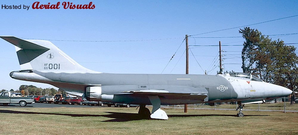
This preserved machine wore a rather unusual (for a Voodoo) ‘Hill’ low-viz scheme with toned-down markings, quite similar to the late USAF F-4 Phantom IIs of the early Eighties. The big aircraft looked quite good in this simple livery, and I kept the idea of a Hill scheme Voodoo in the back of my mind for some years until I recently had the opportunity to buy a cheap Matchbox Voodoo w/o box and decals. With its optional (and unique) RF-101B parts I decided to take the Hill Voodoo idea to the hardware stage and create another submission to the “Reconnaissance and Surveillance” group build at whatifmodellers.com around July 2021: an ANG recce conversion of a former two-seat interceptor, using the RF-101B as benchmark but with a different suite of sensors.
However, the Matchbox Voodoo kit is rather mediocre, and in a rather ambitious mood I decided to “upgrade” the project with a Revell F-101B as the model’s basis. This kit is from 1991 and a MUCH better and finely detailed model than the rather simple Matchbox kit from the early Eighties. In fact, the Revell F-101B is actually a scaled-down version of Monogram’s 1:48 F-101B model kit from 1985, with many delicate details. But while this downscaling practice has produced some very nice 1:72 models like the F-105D or the F-4D, the scaling effect caused IMHO in this case a couple of problems. Revell's assembly instructions for the 1:72 kit are not good, either. While the step-by-step documentation is basically good, some sketches are so cluttered that you cannot tell where parts in the cockpit or on the landing gear are actually intended to be placed and how. This is made worse by the fact that there are no suitable markings on the parts – you are left to guessing.
Worse, there is a massive construction error: the way the wings section is to be assembled and mounted to the hull is impossible! The upper wing halves have locator pins for the fuselage, but they are supposed to be glued to the lower wing half (which also encompasses the aircraft's belly) and the mounted to the hull. The locator pins make this impossible, unless you bend the lower wing section to a point where it might warp or break, or you just cut the pins off - and live with some instability. Technically the upper wing halves have to be mounted to the fuselage before you glue the lower wing section to them, but I am not certain if this would work well because you also have to assemble the air intakes at the same time “from behind”, which is only feasible when the wings have already been completed but still left away from the fuselage. It’s a nonsense construction! I cannot remember when I came across a kit the last time with such an inherent design flaw?
Except for the transplanted RF-101B nose section, which did not fit well because the Matchbox Voodoo apparently has a more slender nose, the Revell kit was built mostly OOB. However, this is already a challenge in itself because of the kit’s inherent flaws (see above), its complex construction and an unorthodox assembly sequence, due to many separate internal modules including the cockpit tub, a separate (fully detailed) front landing gear well, a rotating weapon bay, air intakes with complete ducts, and the wing section. A fiddly affair.
Only a few further changes beyond the characteristic camera fairing under the radome were made. The rotating weapon bay was faired-over with the original weapon pallet, just fixing it into place and using putty to blend it into the belly. The small underwing pylons (an upgrade that actually happened to some late Voodoos) were taken from a vintage Revell F-16. The SLAR antenna fairings along the cockpit flanks were created with 0.5mm styrene sheet and some PSR. They are a little too obvious/protruding, but for a retrofitted solution I find the result acceptable. The drop tanks came from the Revell kit, the underwing ordnance consists of an ALQ-119 ECM pod from a Hasegawa aftermarket set and a SUU-42 dispenser, scratched from a Starfighter ventral drop tank, bomb fins and the back of a Soviet unguided missile launcher.
Painting and markings:
Very simple and basic. While I originally wanted to adopt the simple two-tone ‘Hill’ scheme from the gate guard for my fictional Voodoo, I eventually settled for the very similar but slightly more sophisticated ‘Egypt One’ scheme that was introduced with the first F-16s – it just works better on the F-101’s surfaces. This scheme uses three grey tones: FS 36118 (Gunship Gray, ModelMaster 1723) for the upper wing surfaces, the “saddle” on the fuselage and the canopy area with an anti-glare panel, FS 36270 (Medium Grey, Humbrol 126) on the fin and the fuselage area in front of the wing roots, and FS 36375 (Light Ghost Grey, Humbrol 127) for all lower surfaces, all blended into each other with straight but slightly blurred edges (created with a soft, flat brush). The radome and the conformal antennae on the flanks became Revell 47 for a consistent grey-in-grey look, but with a slightly different shade. The model received an overall black ink washing and some post panel shading, so that the large grey areas would not look too uniform.
As an updated USAF aircraft I changed the color of the landing gear wells’ interior from green zinc chromate primer to more modern, uniform white, even though the red inside of the covers was retained. The interior of the flaps (a nice OOB option of Revell’s kit) and the air brakes became bright red, too.
The cockpit retained its standard medium grey (Humbrol 140, Dark Gull Grey) interior and I used the instrument decals from the kit – even though these did not fit well onto the 3D dashboards and side consoles. WTF? Decal softener came to the rescue. The exhaust area was painted with Revell 91 (Iron) and Humbrol’s Steel Metallizer (27003), later treated with graphite for a dirty, metallic shine.
Markings/decals primarily come from a 1:72 Hi-Decal F-4D sheet that contains (among others) several Texas ANG Phantoms from the mid-Eighties. Some stencils were taken over from the original Voodoo sheet, the yellow formation lights had to be procured from a Hasegawa F-4E/J sheet (the Matchbox sheet was lost and the Revell sheet lacks them completely!). The characteristic deep yellow canopy sealant stripes came from a CF-101 sheet from Winter Valley Decals (today part of Canuck Models as CAD 72008). I was lucky to have them left over from another what-if build MANY moons ago, my fictional CF-151 kitbashing.
Everything went on smoothly, but the walkway markings above the air intakes became a problem. I initially used those from the Revell sheet, which are only the outlines so that the camouflage would still be visible. But the decal film, which is an open square, turned out to be so thin that it wrinkled on the curved surface whatever I tried, and what looked like a crisp black outline on the white decal paper turned out to be a translucent dark blue with blurry edges on the kit. I scrapped them while still wet… Enter plan B: Next came the walkway markings from the aforementioned Winter Valley sheet, which were MUCH better, sharper and opaque, but they included the grey walking areas. While the tone looked O.K. on the sheet it turned out to be much too light for the all-grey Voodoo, standing out and totally ruining the low-viz look. With a bleeding heart I eventually ripped them off of the model with the help of adhesive tape, what left light grey residues. Instead of messing even more with the model I finally decided to embrace this accident and manually added a new black frame to the walkway areas with generic 2mm decal stripe material from TL Modellbau The area now looks rather worn, as if the camouflage had peeled off and light grey primer shows through. An unintentional result, but it looks quite “natural”.
The “Rhino Express” nose art was created with Corel Draw and produced with a simple inkjet printer on clear decal sheet. It was inspired by the “toenail” decoration on the main landing gear covers, a subtle detail I saw IIRC on a late CF-101B and painted onto the model by hand. With its all-grey livery, the rhino theme appeared so appropriate, and the tag on the nose appeared like a natural addition. It’s all not obvious but adds a personal touch to the aircraft.
Finally, after some more exhaust stains had been added to various air outlets around the hull, the model was sealed with matt acrylic varnish, position lights were added with clear paint and the camera windows, which had been created with black decal material, received glossy covers. The IRST sensor was painted with translucent black over a gold base.
Well, while the all-grey USAF livery in itself is quite dull and boring, but I must say that it suits the huge and slender Voodoo well. It emphasizes the aircraft's sleek lines and the Texas ANG fin flash as a colorful counterpoint, as well as the many red interior sections that only show from certain angles, nicely break the adapted low-viz Egypt One livery up. The whole thing looks surprisingly convincing, and the subtle rhino markings add a certain tongue-in-cheek touch.
This camera used 122 film which is no longer available. With a few modifications, you have the possibilty to use this vintage camera with 120 roll films. After conversion, the negative size is 120 x 58 mm. It would have been possible to extend the negative size to 140 mm but my 4x5 inches enlarger couldn't accept these negatives anymore. The new frame is made with a sheet of plastic (black styrene).
The back was also modified : I obstructed the red window and put a red window where we used to write notes on the autographic A122 film.
Adaptors where made for take up spool and for 120 roll film.
In the back, I attached a pressure plate ( a thin sheet of brass) that i fixed with black adhesive tape.
+++ DISCLAIMER +++
Nothing you see here is real, even though the conversion or the presented background story might be based on historical facts. BEWARE!
Some background:
The MBR-04 series were the first combat-ready Destroids and the most successful land-combat weapon Destroids that were built with OverTechnology of Macross. The abbreviation MBR (Main Battle Robot) indicates the model was developed as a walking humanoid weapon emphasizing the heavy armor firepower of an artillery combat vehicle, designed to replace mainline battle tanks.
Despite inferior anti-aircraft abilities, the Tomahawk boasted firepower like no other biped vehicle from the Destroid series. Originally, the Tomahawk was just called "MBR Mk. I", but once its systems and structural elements became the basis for other models, its designation changed into the "Type 04" Destroid. The main frame from the waist down was common to the Type 04 series, which included the the Defender and the Phalanx, a module which consolidated the thermonuclear reactor and ambulatory OverTechnology system of the Destroids. Production line integration using this module was a key goal of Destroid development.
The Type 04 series was developed jointly by Viggers and Chrauler and became also the basis of the MBR-04 Tomahawk. Unlike the variable fighters (which had to be designed to accommodate transformation mechanisms), the MBR series featured a structure with a large capacity that allowed plenty of room for machinery and armor.
Projectile resistance was stressed in the design, but the Tomahawk did not have the armor strength to withstand a direct hit from a Zentraedi mobile weapon. However, the Tomahawk made use of heaviness to add firepower and versatility such that it came to symbolize those features of the Destroid.
First development began in May 2001 and trial production began in December 2003. The decision to formally introduce the MBR-04 series of Destroids was made in June 2006, mass production began and the MBR-04-Mk I rollout occurred in February 2007. The Mk VI Tomahawk's and Mk X Defender's rollouts were in November 2007 and March 2009, respectively.
The MBR-04-Mk. I's initial weaponry consisted of rocket launchers and two arms for use in close-quarters combat. Eventually, the Tomahawk's arms evolved into fixed armaments unsuitable for hand-to-hand combat and thus it was best fielded in a combined arms role with cooperating Destroid models and the VF-1.
The Type 04 design led to expansion of installed armaments and achieved improvement in productivity and serviceability which contributed to the rapid development of the Destroid variations. The Tomahawk itself underwent a rapid development. Earlier variants, which mainly differed in the design of the arms and the weapon package, were only produced in limited numbers. The Mk. III introduced the first heavy particle beam cannon to the Destroids, and the following Mk IV. achieved excellent results in maneuvers and an enhanced output. The Mk. VI became the eventual mass production type, and some of the earlier models were later brought to Mk. VI standard.
Eventually, a considerable number 440 units (initially, 500 were envisioned) were deployed aboard the SDF-1 Macross and operated by the U.N. Spacy as well as the U.N.S. Marine Corps. Most of the Destroid Tomahawks were deployed upon the surface of SDF-1 to perform close-range interception and also to operate as an immediate combat force. A small number - primarily from the early variants with full arms and articulated hands for bigger field versatility in small combat groups - was operated by the UNSMC for landing operations and special tasks.
The Tomahawk operated as a core ground combat unit during the Great Stellar War (Space War I) and - when paired with the VF-1 variable fighter - achieved impressive military gains against the Zentraedi army.
General characteristics:
Equipment Type: main battle robot, series 04
Government: U.N. Spacy
Manufacturer: Viggers/Chrauler
Introduction: February 2007
Accommodation: 1 pilot plus space for a second crew member
Dimensions:
Height 12.7 meters (overall)
11.27 meters (up to head unit)
Length 5.1 meters
Width 7.9 meters
Mass: 31.3 metric tons
Power Plant:
Kranss-Maffai MT808 thermonuclear reactor, developing 2800 bhp output;
Auxiliary GE EM9G fuel generator, rated at 450 kW
Propulsion:
2x thrust nozzles mounted in the lower back region, allowing the capability to perform jumps,
plus several vernier nozzles around the hull for Zero-G manoeuvers
Performance:
Maximum speed: 180 km/h
Design features:
- Detachable weapons bay (attaches to the main body via two main locks);
- Extending/retractable periscope telescope (in weapon bay directly above the cockpit);
- Option pack featuring missiles or searchlight (can be mounted on either side of the weapon bay);
- Coolant tank (installed within the upper left side of the back torso);
- Capable of performing jumps via 2 x thrust nozzles (mounted in the lower back torso);
- Radiators with exhaust ports in the rear on the left and right hips
- Cockpit can be separated from the body in an emergency (only the cockpit block is recovered);
- Head unit equipped with 2 camera eyes, upper eye moving along a slit,
the lower protected by a polarized light shield
Armament:
1x Mauler PBG-07 liquid-cooled electrically-charged twin particle beam gun
2x Bifors close-in self-guided rocket launchers in the shoulders
with 12 rockets per launcher (24 rockets total)
2x Astra TZ-III gun clusters in the lower chest with each cluster featuring:
- 1x laser gun
- 1x 25 mm heavy machine gun
- 1x 180 mm grenade launcher
- 1 x flamethrower
2x Ramington M-89 12.7 mm air-cooled machine guns, mounted within the head unit
Option packs:
1x Erlikon anti-aircraft self-guided missile launcher with 6 missiles (shoulder mount)
1x Rheinstahl 35 mm automatic rapid-fire cannon (lower arm pod)
1x Stonewell 20 mm six-barrel gatling gun (lower arm pod)
The kit and its assembly:
After a long time, a Macross mecha kit again. The idea behind this modified Tomahawk was that I always wondered about the clumsy "cannon arms" of the Mk. VI variant, and what an earlier version - with complete arms and hands - could have looked like? When I delved through my Macross donor parts bank I came across two lower arms from former VF-1 conversions (from different kits, though...), and I tested them on my authentic 1:100 Tomahawk Mk. VI model that I have built about 20 years ago: they seemed to work in size and volume!
An extensive spare parts and sprues safari followed and yielded two complete hands/fists from a VF-1 Gerwalk Arii kit (these appear to be totally outsized!), as well as lower arms/elbow sections, so that a transplantation to the Tomahawk’s arm stumps, which would later even allow a lengthwise axis mobility. And with some extra vinyl caps the transformation experiment could begin.
The basis is a Bandai re-issues of Imai’s 1982 1:100 Tomahawk kit, in specific from Macross' 30th anniversary merchandise. They seem to pop up every five years!?
However, having built and re-built several of the Imai/Arii Destroid kits, I made some changes beyond the arm transplantation, since there’s a lot of space for improvement, even though the kit as such is decent for its age. But you have to expect PSR almost everywhere, and the kit’s vintage “Matryoshka” construction of the model (build one element from two halves, place it between two more halves, etc.) does not make the assembly process easy – but there are ways to evade this inherent problem, see below.
One important improvement measure was a completely now hip joint arrangement. OOB, the Tomahawk's posture is pretty stiff, with the legs and feet straight forward - it's supposed to just stand upright, and with the model’s OOB joint options it is really hard to create a vivid poise. Furthermore, the bolts that hold the legs are prone to break off, even more so because the Tomahawk kit is from the 1st generation of mecha kits, without vinyl caps and just very tight joint fit.
My solution was the implantation of a new hip “bone” made from plastic-coated steel, which is stiff in itself but can be bent in two dimensions. The thighs had to be modified accordingly, since the wire is much thinner than the original bolts. As a convenient trick, the receptor holes in the thighs were simply filled with small vinyl rings - their outer AND inner diameter fit perfectly for the new arrangement. With this trick, a much more dynamic and "natural" leg position could be achieved, also thanks to the Tomahawk’s large feet and their joints. This tuning measure improves the model considerably.
Another change is the Tomahawk's weaponry, which is OOB pretty impressive. Since my fictional Mk. III lost its main arm weapons, I decided to give it at least a major cannon on the shoulder. A convenient donor came from a Dorvack 1:24 PA-36K "Berlon" kit, placed on a scratched mount on the right shoulder,. Which allows the weapon to be moved up and down. To make place for the new twin gun, the OOB sextuple missile launcher was moved to the left side, necessitating a modification of its holder, too.
As mentioned above, the arms use donor parts from the Arii VF-1 Gerwalk kit, but there are also less obvious changes. While the shoulder mounts and the upper arms were taken OOB from the Tomahawk kit, I modified their attachment system. Instead of the "put the arms between the fuselage halves" solution, I modified the arms so that they can be stuck independently into their respective hull openings. This has the benefit that they are actually movable (remember the tight fit of the model’s joints, add some paint and nothing will ever move), and they can be built and painted separately from the rest of the model. In order to stabilize the arms when in place and prevent them from falling out too easily, I added an interlaced styrene tube axis arrangement between them. Very simple and effective, and it works well.
The VF-1 Gerwalk lower arms were taken OOB. Upon test-fitting I found that the bulky Tomahawk could even take some more muscle on its new arms, so I added a pair of FAST packs from a Super Valkyrie kit to them (also found in the spares box…). These would, however, not contain AAMs, as on the VF-1, but rather more guns. I went for a medium machine cannon in the left arm and a gatling gun (scratched from syringe needles, fiddly affair...) against soft and aerial targets in the right arm.
In order to provide the model with some more details and depth I added a lot of small styrene bits everywhere – this is actually only necessary on the front sides of the lower legs for an authentic improvement, but all those other tiny bits and pieces just underline the mecha’s sturdiness and provide visual detail for the later painting process.
The machine guns above the cockpit were replaced with hollow steel needles; since these are thinner than the OOB barrels, I filled the gaps with paper tissues drenched in thinned white glue. Flexible cables (elastic braid) were added to the twin beam cannon and to the legs/hip joints.
Painting and markings:
Basically a simple affair, because I wanted to stay true to the original look of a typical Macross Destroid. These tend to carry a uniform livery, esp. the Tomahawk/Defender/Phalanx family is kept in murky/dull tones of green, brown and ochre: unpretentious "mud movers". Anything else or even complex camouflage patterns are rare. The OOB MBR-04-Mk. VI carries a reddish-brown livery, and Yamato also did an 1:60 Tomahawk action figure in an overall olive drab tone, which appears canonical.
However, for a personal touch I chose a greyish dark green as basic overall tone, Field Grey (Tamiya XF-65). The missile launcher covers on the shoulders were painted in NATO olive green (RAL 6014, Gelboliv, Revell 46), but the different tone became, after weathering, harder and harder to tell, so that the Tomahawk ended up with a relatively uniform livery.
Otherwise there's hardly any other color on the Tomahawk’s hull. The hands/fists were painted with Polished Steel metallizer, the bellows in the knees became anthracite (Revell 06). The characteristic white trim on the lower legs that many Destroids carry was painted with white - unfortunately none of the Destroid kits offers them as a decal. However, due to the legs' uneven underground, these would be difficult to apply, anyway. The lower camera visor was created with simple clear red paint on top of a basic coat with silver. The other small camera windows at the top and back are small decal squares in dayglo orange.
The model was thoroughly weathered with a heavier black ink wash and a total of three dry brushing turns: the first, generous treatment with acrylic Revell 67 (Grüngrau, RAL 7009), followed by the second, moer careful turn around the edges and other details with acrylic Revell 45 (Helloliv, a yellowish variant of RLM 02). The decals followed next, mostly taken from the OOB sheet, just with a few extra stencils, new tactical codes and the "Trixie” nose art (it actually belongs to a P-40F, piloted by Joseph A Bloomer Jr of the 318th FS/325th FG in the MTO) on the lower left leg – a typical detail of many Destroids.
The third dry brushing turn followed, this time with acrylic Revell 75 (a yellowish light grey), esp. on the edges and concentrated around the lower areas of the Tomahawk, simulating wear and dust/mud residue.
Finally, the model received an overall coat with acrylic matt varnish from the rattle can. Some bare metal showing through at a few edges was added, too, again through dry-brushing with silver. After final assembly of the elements, some mineral pigments were dusted onto the model with a soft, big brush. Around the feet, pigments were also applied into small patches of wet matt acrylic varnish, forming stable mud crusts.
In the end, I am quite happy with the outcome, even though the Field Grey turned out to be darker/more murky than expected, even though the color itself suits the Tomahawk well. The transplanted arms also blend well into this mecha which bristles with weapons: this fictional (I had no reference material for earlier Tomahawk versions except the official short texts from the Macross publications) result looks pretty plausible and complements the 20-years-old Mk. VI in my collection well.
+++ DISCLAIMER +++
Nothing you see here is real, even though the conversion or the presented background story might be based on historical facts. BEWARE!
Some background:
The CAC Sabre, sometimes known as the Avon Sabre or CA-27, was an Australian variant of the North American Aviation F-86F Sabre fighter aircraft. In 1951, Commonwealth Aircraft Corporation obtained a license agreement to build the F-86F Sabre. In a major departure from the North American blueprint, it was decided that the CA-27 would be powered by a license-built version of the Rolls-Royce Avon R.A.7, rather than the General Electric J47. In theory, the Avon was capable of more than double the maximum thrust and double the thrust-to-weight ratio of the US engine. This necessitated a re-design of the fuselage, as the Avon was shorter, wider and lighter than the J47.
To accommodate the Avon, over 60 percent of the fuselage was altered and there was a 25 percent increase in the size of the air intake. Another major revision was in replacing the F-86F's six machine guns with two 30mm ADEN cannon, while other changes were also made to the cockpit and to provide an increased fuel capacity.
The prototype aircraft first flew on 3 August 1953. The production aircrafts' first deliveries to the Royal Australian Air Force began in 1954. The first batch of aircraft were powered by the Avon 20 engine and were designated the Sabre Mk 30. Between 1957 and 1958 this batch had the wing slats removed and were re-designated Sabre Mk 31. These Sabres were supplemented by 20 new-built aircraft. The last batch of aircraft were designated Sabre Mk 32 and used the Avon 26 engine, of which 69 were built up to 1961.
Beyond these land-based versions, an indigenous version for carrier operations had been developed and built in small numbers, too, the Sea Sabre Mk 40 and 41. The roots of this aircraft, which was rather a prestigious idea than a sensible project, could be traced back to the immediate post WWII era. A review by the Australian Government's Defence Committee recommended that the post-war forces of the RAN be structured around a Task Force incorporating multiple aircraft carriers. Initial plans were for three carriers, with two active and a third in reserve, although funding cuts led to the purchase of only two carriers in June 1947: Majestic and sister ship HMS Terrible, for the combined cost of AU£2.75 million, plus stores, fuel, and ammunition. As Terrible was the closer of the two ships to completion, she was finished without modification, and was commissioned into the RAN on 16 December 1948 as HMAS Sydney. Work progressed on Majestic at a slower rate, as she was upgraded with the latest technology and equipment. To cover Majestic's absence, the Colossus-class carrier HMS Vengeance was loaned to the RAN from 13 November 1952 until 12 August 1955.
Labour difficulties, late delivery of equipment, additional requirements for Australian operations, and the prioritization of merchant ships over naval construction delayed the completion of Majestic. Incorporation of new systems and enhancements caused the cost of the RAN carrier acquisition program to increase to AU£8.3 million. Construction and fitting out did not finish until October 1955. As the carrier neared completion, a commissioning crew was formed in Australia and first used to return Vengeance to the United Kingdom.
The completed carrier was commissioned into the RAN as HMAS Majestic on 26 October 1955, but only two days later, the ship was renamed Melbourne and recommissioned.
In the meantime, the rather political decision had been made to equip Melbourne with an indigenous jet-powered aircraft, replacing the piston-driven Hawker Fury that had been successfully operated from HMAS Sydney and HMAS Vengeance, so that the "new jet age" was even more recognizable. The choice fell on the CAC Sabre, certainly inspired by North American's successful contemporary development of the navalized FJ-2 Fury from the land-based F-86 Sabre. The CAC 27 was already a proven design, and with its more powerful Avon engine it even offered a better suitability for carrier operations than the FJ-2 with its rather weak J47 engine.
Work on this project, which was initially simply designated Sabre Mk 40, started in 1954, just when the first CAC 27's were delivered to operative RAAF units. While the navalized Avon Sabre differed outwardly only little from its land-based brethren, many details were changed and locally developed. Therefore, there was also, beyond the general outlines, little in common with the North American FJ-2 an -3 Fury.
Externally, a completely new wing with a folding mechanism was fitted. It was based on the F-86's so-called "6-3" wing, with a leading edge that was extended 6 inches at the root and 3 inches at the tip. This modification enhanced maneuverability at the expense of a small increase in landing speed due to deletion of the leading edge slats, a detail that was later introduced on the Sabre Mk 31, too. As a side benefit, the new wing leading edges without the slat mechanisms held extra fuel. However, the Mk 40's wing was different as camber was applied to the underside of the leading edge to improve low-speed handling for carrier operations. The wings were provided with four stations outboard of the landing gear wells for up to 1000 lb external loads on the inboard stations and 500 lb on the outboard stations.
Slightly larger stabilizers were fitted and the landing gear was strengthened, including a longer front wheel strut. The latter necessitated an enlarged front wheel well, so that the front leg’s attachment point had to be moved forward. A ventral launch cable hook was added under the wing roots and an external massive arrester hook under the rear fuselage.
Internally, systems were protected against salt and humidity and a Rolls-Royce Avon 211 turbojet was fitted, a downrated variant of the already navalized Avon 208 from the British DH Sea Vixen, but adapted to the different CAC 27 airframe and delivering 8.000 lbf (35.5 kN) thrust – slightly more than the engines of the land-based CAC Sabres, but also without an afterburner.
A single Mk 40 prototype was built from a new CAC 27 airframe taken directly from the production line in early 1955 and made its maiden flight on August 20th of the same year. In order to reflect its naval nature and its ancestry, this new CAC 27 variant was officially christened “Sea Sabre”.
Even though the modified machine handled well, and the new, cambered wing proved to be effective, many minor technical flaws were discovered and delayed the aircraft's development until 1957. These included the wing folding mechanism and the respective fuel plumbing connections, the landing gear, which had to be beefed up even more for hard carrier landings and the airframe’s structural strength for catapult launches, esp. around the ventral launch hook.
In the meantime, work on the land-based CAC 27 progressed in parallel, too, and innovations that led to the Mk 31 and 32 were also incorporated into the naval Mk 40, leading to the Sea Sabre Mk 41, which became the effective production aircraft. These updates included, among others, a detachable (but fixed) refueling probe under the starboard wing, two more pylons for light loads located under the wing roots and the capability to carry and deploy IR-guided AIM-9 Sidewinder air-to-air missiles, what significantly increased the Mk 41's efficiency as day fighter. With all these constant changes it took until April 1958 that the Sabre Mk 41, after a second prototype had been directly built to the new standard, was finally approved and cleared for production. Upon delivery, the RAN Sea Sabres carried a standard NATO paint scheme with Extra Dark Sea Grey upper surfaces and Sky undersides.
In the meantime, the political enthusiasm concerning the Australian carrier fleet had waned, so that only twenty-two aircraft were ordered. The reason behind this decision was that Australia’s carrier fleet and its capacity had become severely reduced: Following the first decommissioning of HMAS Sydney in 1958, Melbourne became the only aircraft carrier in Australian service, and she was unavailable to provide air cover for the RAN for up to four months in every year; this time was required for refits, refueling, personnel leave, and non-carrier duties, such as the transportation of troops or aircraft. Although one of the largest ships to serve in the RAN, Melbourne was one of the smallest carriers to operate in the post-World War II period, so that its contribution to military actions was rather limited. To make matters worse, a decision was made in 1959 to restrict Melbourne's role to helicopter operations only, rendering any carrier-based aircraft in Australian service obsolete. However, this decision was reversed shortly before its planned 1963 implementation, but Australia’s fleet of carrier-borne fixed-wing aircraft would not grow to proportions envisioned 10 years ago.
Nevertheless, on 10 November 1964, an AU£212 million increase in defense spending included the purchase of new aircraft for Melbourne. The RAN planned to acquire 14 Grumman S-2E Tracker anti-submarine aircraft and to modernize Melbourne to operate these. The acquisition of 18 new fighter-bombers was suggested (either Sea Sabre Mk 41s or the American Douglas A-4 Skyhawk), too, but these were dropped from the initial plan. A separate proposal to order 10 A-4G Skyhawks, a variant of the Skyhawk designed specifically for the RAN and optimized for air defense, was approved in 1965, but the new aircraft did not fly from Melbourne until the conclusion of her refit in 1969. This move, however, precluded the production of any new and further Sea Sabre.
At that time, the RAN Sea Sabres received a new livery in US Navy style, with upper surfaces in Light Gull Gray with white undersides. The CAC Sea Sabres remained the main day fighter and attack aircraft for the RAN, after the vintage Sea Furies had been retired in 1962. The other contemporary RAN fighter type in service, the Sea Venom FAW.53 all-weather fighter that had replaced the Furies, already showed its obsolescence.
In 1969, the RAN purchased another ten A-4G Skyhawks, primarily in order to replace the Sea Venoms on the carriers, instead of the proposed seventh and eighth Oberon-class submarines. These were operated together with the Sea Sabres in mixed units on board of Melbourne and from land bases, e.g. from NAS Nowra in New South Wales, where a number of Sea Sabres were also allocated to 724 Squadron for operational training.
Around 1970, Melbourne operated a standard air group of four jet aircraft, six Trackers, and ten Wessex helicopters until 1972, when the Wessexes were replaced with ten Westland Sea King anti-submarine warfare helicopters and the number of jet fighters doubled. Even though the A-4G’s more and more took over the operational duties on board of Melbourne, the Sea Sabres were still frequently deployed on the carrier, too, until the early Eighties, when both the Skyhawks and the Sea Sabres received once more a new camouflage, this time a wraparound scheme in two shades of grey, reflecting their primary airspace defense mission.
The CAC 27 Mk 41s’ last carrier operations took place in 1981 in the course of Melbourne’s involvements in two major exercises, Sea Hawk and Kangaroo 81, the ship’s final missions at sea. After Melbourne was decommissioned in 1984, the Fleet Air Arm ceased fixed-wing combat aircraft operation. This was the operational end of the Sabre Mk 41, which had reached the end of their airframe lifetime, and the Sea Sabre fleet had, during its career, severely suffered from accidents and losses: upon retirement, only eight of the original twenty-two aircraft still existed in flightworthy condition, so that the aircraft were all scrapped. The younger RAN A-4Gs were eventually sold to New Zealand, where they were kept in service until 2002.
General characteristics:
Crew: 1
Length: 37 ft 6 in (11.43 m)
Wingspan: 37 ft 1 in (11.3 m)
Height: 14 ft 5 in (4.39 m)
Wing area: 302.3 sq ft (28.1 m²)
Empty weight: 12,000 lb (5,443 kg)
Loaded weight: 16,000 lb (7,256 kg)
Max. takeoff weight: 21,210 lb (9,621 kg)
Powerplant:
1× Rolls-Royce Avon 208A turbojet engine with 8,200 lbf (36.44 kN)
Performance:
Maximum speed: 700 mph (1,100 km/h) (605 knots)
Range: 1,153 mi, (1,000 NM, 1,850 km)
Service ceiling: 52,000 ft (15,850 m)
Rate of climb: 12,000 ft/min at sea level (61 m/s)
Armament:
2× 30 mm ADEN cannons with 150 rounds per gun
5,300 lb (2,400 kg) of payload on six external hardpoints;
Bombs were usually mounted on outer two pylons as the mid pair were wet-plumbed pylons for
2× 200 gallons drop tanks, while the inner pair was usually occupied by a pair of AIM-9 Sidewinder
AAMs
A wide variety of bombs could be carried with maximum standard loadout being 2x 1,000 lb bombs
or 2x Matra pods with unguided SURA missiles plus 2 drop tanks for ground attacks, or 2x AIM-9 plus
two drop tanks as day fighter
The kit and its assembly:
This project was initially inspired by a set of decals from an ESCI A-4G which I had bought in a lot – I wondered if I could use it for a submission to the “In the navy” group build at whatifmodelers.com in early 2020. I considered an FJ-3M in Australian colors on this basis and had stashed away a Sword kit of that aircraft for this purpose. However, I had already built an FJ variant for the GB (a kitbashed mix of an F-86D and an FJ-4B in USMC colors), and was reluctant to add another Fury.
This spontaneously changed after (thanks to Corona virus quarantine…) I cleaned up one of my kit hoards and found a conversion set for a 1:72 CAC 27 from JAYS Model Kits which I had bought eons ago without a concrete plan. That was the eventual trigger to spin the RAN Fury idea further – why not a navalized version of the Avon Sabre for HMAS Melbourne?
The result is either another kitbash or a highly modified FJ-3M from Sword. The JAYS Model Kits set comes with a THICK sprue that carries two fuselage halves and an air intake, and it also offers a vacu canopy as a thin fallback option because the set is actually intended to be used together with a Hobby Craft F-86F.
While the parts, molded in a somewhat waxy and brittle styrene, look crude on the massive sprue, the fuselage halves come with very fine recessed engravings. And once you have cleaned the parts (NOTHING for people faint at heart, a mini drill with a saw blade is highly recommended), their fit is surprisingly good. The air intake was so exact that no putty was needed to blend it with the rest of the fuselage.
The rest came from the Sword kit and integrating the parts into the CAC 27 fuselage went more smoothly than expected. For instance, the FJ-3M comes with a nice cockpit tub that also holds a full air intake duct. Thanks to the slightly wider fuselage of the CAC 27, it could be mounted into the new fuselage halves without problems and the intake duct almost perfectly matches the intake frame from the conversion set. The tailpipe could be easily integrated without any mods, too. The fins had to be glued directly to the fuselage – but this is the way how the Sword kit is actually constructed! Even the FJ-3M’s wings match the different fuselage perfectly. The only modifications I had to make is a slight enlargement of the ventral wing opening at the front and at the read in order to take the deeper wing element from the Sword kit, but that was an easy task. Once in place, the parts blend almost perfectly into each other, just minor PSR was necessary to hide the seams!
Other mods include an extended front wheel well for the longer leg from the FJ-3M and a scratched arrester hook installation, made from wire, which is on purpose different from the Y-shaped hook of the Furies.
For the canopy I relied on the vacu piece that came with the JAYS set. Fitting it was not easy, though, it took some PSR to blend the windscreen into the rest of the fuselage. Not perfect, but O.K. for such a solution from a conversion set.
The underwing pylons were taken from the Sword kit, including the early Sidewinders. I just replaced the drop tanks – the OOB tanks are very wide, and even though they might be authentic for the FJ-3, I was skeptical if they fit at all under the wings with the landing gear extended? In order to avoid trouble and for a more modern look, I replaced them outright with more slender tanks, which were to mimic A-4 tanks (USN FJ-4s frequently carried Skyhawk tanks). They actually come from a Revell F-16 kit, with modified fins. The refueling probe comes from the Sword kit.
A last word about the Sword kit: much light, but also much shadow. While I appreciate the fine surface engravings, the recognizably cambered wings, a detailed cockpit with a two-piece resin seat and a pretty landing gear as well as the long air intake, I wonder why the creators totally failed to provide ANY detail of the arrester hook (there is literally nothing, as if this was a land-based Sabre variant!?) or went for doubtful solutions like a front landing gear that consists of five(!) single, tiny parts? Sadism? The resin seat was also broken (despite being packed in a seperate bag), and it did not fit into the cockpit tub at all. Meh!
Painting and markings:
From the start I planned to give the model the late RAN A-4Gs’ unique air superiority paint scheme, which was AFAIK introduced in the late Seventies: a two-tone wraparound scheme consisting of “Light Admiralty Grey” (BS381C 697) and “Aircraft Grey” (BS 381C 693). Quite simple, but finding suitable paints was not an easy task, and I based my choice on pictures of the real aircraft (esp. from "buzz" number 880 at the Fleet Air Arm Museum, you find pics of it with very good light condition) rather than rely on (pretty doubtful if not contradictive) recommendations in various painting instructions from models or decal sets.
I wanted to keep things simple and settled upon Dark Gull Grey (FS 36231) and Light Blue (FS 35414), both enamel colors from Modelmaster, since both are rather dull interpretations of these tones. Esp. the Light Blue comes quite close to Light Admiralty Grey, even though it should be lighter for more contrast to the darker grey tone. But it has that subtle greenish touch of the original BS tone, and I did not want to mix the colors.
The pattern was adapted from the late A-4Gs’ scheme, and the colors were dulled down even more through a light black ink wash. Some post-shading with lighter tones emphasized the contrast between the two colors again. And while it is not an exact representation of the unique RAN air superiority scheme, I think that the overall impression is there.
The cockpit interior was painted in very dark grey, while the landing gear, its wells and the inside of the air intake became white. A red rim was painted around the front opening, and the landing gear covers received a red outline, too. The white drop tanks are a detail I took from real world RAN A-4Gs - in the early days of the air superiority scheme, the tanks were frequently still finished in the old USN style livery, hence the white body but fins and tail section already in the updated colors.
The decals became a fight, though. As mentioned above, the came from an ESCI kit – and, as expected, the were brittle. All decals with a clear carrier film disintegrated while soaking in water, only those with a fully printed carrier film were more or less usable. One roundel broke and had to be repaired, and the checkered fin flash was a very delicate affair that broke several times, even though I tried to save and repair it with paint. But you can unfortunately see the damage.
Most stencils and some replacements (e. g. the “Navy” tag) come from the Sword FJ-3. While these decals are crisply printed, their carrier film is utterly thin, so thin that applying esp. the larger decals turned out to be hazardous and complicated. Another point that did not really convince me about the Sword kit.
Finally, the kit was sealed with matt acrylic varnish (Italeri) and some soot stains were added around the exhaust and the gun ports with graphite.
In the end, this build looks, despite the troubles and the rather exotic ingredients like a relatively simple Sabre with Australian markings, just with a different Navy livery. You neither immediately recognize the FJ-3 behind it, nor the Avon Sabre’s bigger fuselage, unless you take a close and probably educated look. Very subtle, though.
The RAN air superiority scheme from the late Skyhawks suits the Sabre/Fury-thing well – I like the fact that it is a modern fighter scheme, but, thanks to the tones and the colorful other markings, not as dull and boring like many others, e. g. the contemporary USN "Ghost" scheme. Made me wonder about an early RAAF F-18 in this livery - should look very pretty, too?
I am a bit of a Grinch
Last weekend at Galgorm Hotel
Anyway I now have an excuse to play my favourite Christmas song. From the late, great, Poly Styrene, it was released about 6 months before she died.
Poly Styrene - Black Christmas
+++ DISCLAIMER +++
Nothing you see here is real, even though the conversion or the presented background story might be based historical facts. BEWARE!
Some background:
The US Marine Corps' lessons learned from the Korean war included the need for a ground attack aircraft with a better performance than the AU-1 Corsair, as well as a higher effectiveness than the jet fighters of the 50ies era.
The AU-1 (re-designated from F4U-6) had been a dedicated U.S. Marines attack variant of the Vought F4U fighter with extra armor to protect the pilot and fuel tank, and the oil coolers relocated inboard to reduce vulnerability to ground fire. The fighter's supercharger had been simplified as the design was intended for low-altitude operation. Extra weapon racks were also fitted.
Ready for combat the AU-1 weighed 20% more than a fully loaded F4U-4 and was capable of carrying 8,200 lb of bombs, missiles or drop tanks. The AU-1 had a maximum speed of 238 miles per hour at 9,500 ft, when loaded with 4,600 lb of bombs and a 150-gallon drop-tank. When loaded with eight rockets and two 150-gallon drop-tanks, maximum speed was 298 mph at 19,700 ft. When not carrying external loads, maximum speed was 389 mph at 14,000 ft.
First produced in 1952, the AU-1 had been a useful addition. But it had become clear, by the end of the Korean War, that the age of the piston engine fighter plane was more or less over. Based on this insight and several studies based on the experience since WWII, Vought offered the USMC an improved ground attack aircraft on a private venture basis under the internal project handle V-381.
The machine was the result of initial attack aircraft studies and roughly based on the F4U's outlines, and a more conservative alternative to the A2U, a proposed attack derivative of the F7U Cutlass, which never came to fruition.
The V-381 study incorporated proven elements like the characteristic inverted gull wing, which allowed a short and sturdy landing gear, but it differed considerably in many other details and its internal structure, due to a different engine. The aircraft was to be powered by a T-56 turboprop engine and would fit into a heavier class than the F4U, rather comparable to the US Navy's AD Skyraider but almost as fast as a jet fighter of its time – yet more reliable and rugged for low level operations in direct range of small caliber weapons.
The USMC was immediately interested, while the USN declined the proposal (even though much of the V-381’s insights were re-used in the V-406). Compared with the AU-1, the XA3U featured many detail improvements. One of these distinctive modifications was a new cockpit with a bubble canopy. Thanks to the different internal layout of the aircraft the cockpit could be moved forward by about 3', eliminating the abysmal field of view from the F4U's cockpit on the ground and during deck landings. Another significant change was a cruciform tail. This new arrangement had become necessary in order to avoid damage and turbulences from the hot turboprop efflux - the latter's exhaust was bifurcated and placed in the fuselage flanks, slightly deflected downwards and right at the wings' trailing edge, where the residual thrust from the engine helped during liftoff. The characteristic tail arrangement also became the source of the aircraft's official name, the 'Sea Scorpion'.
Armament consisted of four 0.79 in (20 mm) M2 cannon with 250 RPG in the wings, plus a total of fifteen hardpoints under fuselage and wings for a wide range of ordnance and a total weight of 8,000 lb (3,600 kg). The landing gear retracted backwards into the wings, rotating 90°, and the tail wheel with an attached arrester hook was fully retractable, too. The T-56 turboprop with 4.050 hp (2.977 kW) replaced the R-2800 radial and its complex compressor installment, driving a four-blade Hamilton propeller on the XA2U.
In June 1954 the first XA3U prototype made its maiden flight. Initial flights tests showed a very good performance at low and medium altitude, but directional stability was rather poor and the fin area had to be enlarged, resulting in the X3AU-1. Another new feature became a reversible six blade propeller of smaller diameter, which would improve reaction time to throttle input. In this guise, the A3U-1 entered series production and USMC service in early 1956, just in time to take the place of the AU-1 which was phased out in 1957.
But, by that time, the technical development had already rendered the A3U at least questionable, if not obsolete, so only a single batch of 45 aircraft was ordered and eventually built. Types like the North American FJ-4 Fury or the Douglas A4D Skyhawk offered a better performance as well as a nuclear strike capability that the A3U lacked, even though the turboprop aircraft was popular because of its ruggedness and good low altitude handling.
With its sophisticated design the A3U served well in its intended shipborne CAS role. In 1958 the machines were upgraded to carry AGM-12 Bullpup missiles, becoming subsequently designated A3U-2. Up to four missiles could be carried under the wings, plus a guidance pod that was carried on one of the outermost wing hardpoints.
The A3Us were deployed during several occasions, including Cuba from 1959 to 1960 to protect Americans during the Cuban Revolution, Thailand in May-July 1962 to support the government's struggles against Communists as well as Operation Power Pack in 1965 in Haiti to prevent a second Communist nation on America's doorstep.
Anyway, no A3U actually fired in anger, their main task had rather been sabre-rattling and representing the USMC with dramatic weapon loads at low altitude. Since ever more potent aircraft entered the USMC, like the F-4 Phantom II, the Sea Scorpion's career ended already in 1968 – and despite its usefulness in the theatre of operations, the A2U was not deployed to Vietnam.
General characteristics:
Crew: 1 pilot
Length: 33 ft 8 in (10.2 m)
Wingspan: 41 ft 0 in (12.5 m)
Wingspan, folded: 17 ft 0.5 in (5.2 m)
Height: 14 ft 9 in (4.50 m)
Empty weight: 11,968 lb (5,429 kg)
Loaded weight: 18,106 lb (8,213 kg)
Max. takeoff weight: 25,000 lb (11,340 kg)
Powerplant:
1× Allison T-56-A-6 turboprop engine, rated at 4.050 hp (2.977 kW)
plus approximately 750 lbs of thrust from the exhaust
Performance:
Maximum speed: 446 mph (717 km/h) at 26.200 ft (using emergency power)
Stall speed: 89 mph (143 km/h) clean
Range: 1,316 mi (1,144 nmi, 2,115 km) on internal fuel
Service ceiling: 41,500ft (12,649 m)
Rate of climb: 3,870ft/min (19.7 m/s) at sea-level
Armament:
4 × 0.79 in (20 mm) M2 cannon with 250 RPG in the wings
15 hardpoints for a total of up to 8,000 lb (3,600 kg) of ordnance, including bombs,
torpedoes, mine dispensers, unguided rockets, and gun pods
The kit and its assembly:
Well, this Frankenstein creation was actually spawned by the rather simple idea of a turboprop-powered F4U, following a discussion at whatifmodelers.com concerning my “Turbo Fury” conversion and the potential of T-56 engine nacelles from a C-130 on other aircraft. After three Turbo Furies I still had a final T-56 resin nacelle left in the stash (from OzMods), and eventually tackled this project with the idea of an AU-1 replacement for the USMC in the mid Fifties.
Anyway, with such a modernized version in mind, new ideas popped up – e.g. square wing tips. When I found a pair of leftover outer wings from a Matchbox A3D Skyknight (and they matched up well in shape and size, even the wing profile!) things unfolded into something … different.
The basis for this project was an Italeri F4U-5 from 1994 (a very nice kit!), even though in the later Revell re-boxing. The Skyknight wings replaced the F4U’s outer wings and added about 1” total wingspan to the kit. In order to compensate for this, I thought about moving the tail fin further back, but eventually implanted a completely new and slightly longer tail section from an A.W. Meteor night fighter (also Matchbox), because it perfectly extends the F4U’s fuselage lines! Consequently, the original tail wheel well had to be closed and moved backwards.
Another idea was to move the cockpit forward and lower the rear fuselage, for a more up-to-date bubble canopy. The OOB cockpit from the F4U was kept but placed under a new opening – more or less located where the F4U’s main fuselage tank would have been. The ejection seat is new, too, and the canopy comes from a vintage NOVO Supermarine Attacker. The whole spine was cut away and re-sculpted with putty, as well as the fuselage section around the canopy.
For the new resin T-56, the front end of the fuselage was cut away and lots of putty and sculpting created a new transition between the narrower Herc engine with its oval diameter and the round F4U fuselage.
The spinner comes from the OzMod engine set, but the propeller blades were scratched: these once belonged to a vintage Airfix D.H. Mosquito kit. The rather massive, single blades were cut off, their originally round tips squared and then glued onto the resin spinner. A metal axis and a styrene adapter inside of the resin engine were added as adapters, allowing a free spin.
Once the fuselage and the wings were mated, the horizontal stabilizers had to be added. The F4U parts could not be used because of their round tips, and they had become just too small for the bigger airframe. Implants had to be used once more, and in this case the stabilizers are the outer wing sections from a heavily rivet-infected 1:100 Breguet Alize from Heller. Odd, but they had just the right shape and chord length for the new position.
After these had been fitted, the fin turned out to be too small for the new and overall bigger aircraft. Finding a solution was not easy, and I eventually added a new fin tip, a part from a Revell (FROG) P-39 stabilizer, maybe 30 years old!
In order to make the intended CAS role believable a LOT of hardpoints were added, all taken from an old Airfix/Heller A-1E Skyraider. The ordnance is an iron bomb mix, IIRC these come from a Monogram A-10 and a Matchbox A-7D.
Anyway, building this monstrosity was massive kitbashing work, and the whole thing evolved rather gradually: What started as a simple engine swap and maybe some cosmetic surgery ended up in multiple body transplants and a bigger aircraft than originally envisaged, kind of a ‘Skyraider 2.0’.
Painting and markings:
Nothing truly fancy, rather the standard USN high-viz livery with Light Gull Grey (FS 36440, Modelmaster enamel) upper surfaces and white undersides and rudders. Compared to the USN, the USMC machines would be rather timid and less flamboyant concerning marking colors, so I only added a little red trim to the fin and around the cockpit. The landing gear and the respective wells were kept in white, like the undersides, with bright red trim around the edges, and the cockpit is Zinc Chromate Green.
The decals were puzzled together from the scrap box. Since almost and surface details was lost due to the massive bodywork on fuselage and wings, I painted some panel lines with a pencil and emphasized them with lighter, dry-brushed panel shadings. The effect, at least from some distance, turned out much better than expected! Additionally, some wear and dirt was simulated through a light black in wash. Soot stains, esp. around the jet exhausts, were created with grinded graphite, and some dry painting with silver was done on the leading edges. Finally, everything was sealed under a coat of matt acrylic varnish.
Well, what was to simply become a turboprop-powered F4U turned into something …different. The A3U looks exotic, but not bad or implausible – the thing reminds me of the offspring between a Ju 87 dive bomber and a Westland Whirlwind fighter, and there’s some Fairey Firefly an Il-2 single-seater lineage to it, too? As a positive aspect, this kitbash model reminds IMHO at first glance only remotely of the F4U that it once was, so I think the whiffing work is quite effective. :D
+++ DISCLAIMER +++
Nothing you see here is real, even though the conversion or the presented background story might be based historical facts. BEWARE!
Canadair’s impressive CF-151 ‘Kodiak’ interceptor had a long development story, and the fact that Canada developed an indigenous high-end fighter after the demise of Avro Canada’s CF-105 ‘Arrow’ in the late 50ies was an amazing achievement.
The Kodiak’s stillborn predecessor, the Avro Canada CF-105 ‘Arrow’, was a heavy interceptor aircraft, designed and built by Avro Canada as the culmination of a design study that began in 1953. Considered to be both an advanced technical and aerodynamic achievement for the Canadian aviation industry, the delta wing CF-105 held the promise of near Mach 3 speeds at altitudes likely exceeding 60,000 ft. (18,000 m), and was intended to serve as the Royal Canadian Air Force's (RCAF) primary interceptor in the 1960s and beyond.
It was a very promising aircraft, but not long after the 1958 start of its flight test program, the development of the Arrow (including its Orenda Iroquois jet engines) was abruptly and controversially halted before the project review in 1959 had taken place, sparking a long and bitter political debate. UK also had interest in the Arrow, but this, too, was halted when the Government decided that the age of manned fighters had come to an end – the EE Lightning was just lucky enough to survive this decision.
Anyway, this sudden end to the national interceptor project left Canada with a touchy defense gap in the vast Northern Territories. In 1961, the RCAF obtained 66 CF-101 Voodoo aircraft, one of the American designs the RCAF originally rejected, to serve in the role originally intended for the Avro Arrow. But this was only seen as a stopgap solution – what was needed was a missile-equipped long range interceptor with excellent range, loiter time and the ability to make prolonged dashes at high speed. A true dogfight capability was not required, since it was expected that the targets would be heavy bombers, coming in at high altitudes and subsonic speed.
With the technical advances in the late 60ies, variable geometry aircraft became a promising solution to combine these requirements in a single airframe. Canadair (at that time heavily linked with General Dynamics in the USA) started in 1962 a design study for a heavy swing wing interceptor for the RCAF, which would replace the Voodoos in the 70ies. This was surely driven by the multi-purpose F-111 development for both USAF and USN at that era, but the Canadian aircraft would be a completely new design, tailored to the local needs and with an indigenous weapon system.
The project received the internal code of CL-151 and was an impressive, if not elegant aircraft: with its low-set wings and the tandem cockpit for pilot and system operator it differed greatly from the F-111.
Most fuel was carried in the fuselage, between the air intake ducts and the fixed wing roots. Only the outer wing parts were moveable – a much simpler construction than the F-111. The main weapons, exclusively missiles, were carried semi-recessed under the fuselage, even though pylons under the fixed wing parts, just outside of the landing gear wells, could carry drop tanks. Additional smaller hardpoints on the inner wings' leading egdes could carry up to two Sidewinder AAMs each for short range combat and self-defense. An internal gun was not mounted, even though external SUU-23 gun pods were an option.
Unique features of the CL-151 were its ability to take-off and land on semi-prepared airstrips (specifically, on packed snow and soggy ground), so it received a massive landing gear with low presure twin wheels on all legs, as well as an arrestor hook for forced landings. In order to fit the main landing gear into the wing roots without sacrificing too much depth in the fuselage it received tandem bogies, similar to the Swedish Saab A37 Viggen. Another novel feature was an APU, which was installed together with a heat exchanger in the fin root, so that the CL-151 could be operated with as little maintenance infrastructure as possible.
Core of the CL-151 weapon system was the indigenous CMG-151 radar. This was a state-of-the-art all-weather, multi-mode X-Band pulse doppler radar system with a huge 38” dish antenna in the aircraft’s nose - light years ahead of the vintage Hughes MG-13 fire control radar of the F-102, which was also installed in the CF-101, a design of the early 50ies.
Functionally the CMG-151 was very similar to the American AN/AWG-9, even though less capable. It was designed to detect bomber-sized targets at ranges exceeding 60 miles (100 km) and it featured look-down/shoot-down capabilities, making the fighter suitable to various interception tasks, e .g. against low flying tactical bombers.
The CMG-151 offered a variety of air-to-air modes including long-range continuous wave velocity search, range-while-search at shorter ranges, and the first use of an airborne track-while-scan mode with the ability to track up to 16 airborne targets, display 8 of them on the cockpit displays, and launch against 4 of them at the same time. This function was originally designed to allow the CL-151 to shoot down formations of bombers at long range. The CMG was also coupled with an infrared sighting and tracking (IRST) under the aircraft's nose, which offered with a fire control system enhancement against hostile ECM. This feature was incororated in parallel to "Project Bold Journey", which was an CAF F-101B upgrade programm, running from 1963-66.
There was also a projected, corresponding long-range missile, the AIM-151 ‘Swan’. This was a derivate of the US-American Bendix AAM-N-10 ‘Eagle’, which had been developed for the US Navy’s fruitless ‘Missileer’ program. During its development, the capabilities of the new missile grew tremendously. Growing ever larger, the missile's range was extended to 100 miles (160 km), using an Aerojet-General XM59 solid-fuel motor. Since this would be beyond the range of effective semi-active homing, a new active-radar terminal seeker was added to the missile. But things got more and more complicated, and in the end the AIM-151 was cancelled in 1966. Nevertheless, the CL-151 needed a guided weapon to fulfil its task - and the aircraft' armament were also an important political decision, since the CF-101’s unguided, nuclear AIR-2A ‘Genie’ missiles had been a constant issue of debate and controversy.
In the end, and as a cost-effective compromise, an updated version of the AIM-7E 'Sparrow' was bought, the AIM-7EC. This version was optimized for a longer range (50ml/80km) and equipped with better avionics, making it comparable to the British Sky Flash AAM. Four of these weapons could be carried under the fuselage, and up to four more could be mounted on the wing hardpoints.
Overall, the CL-151 system was a very ambitious and prestigious project – just like the failed CH-105 before. It was not before 3rd of April 1968 until the first prototype made its maiden flight in Montreal. The aircraft’s all light-grey livery and sheer, massive size earned it the nicknames ‘Moby Dick’ and "Grey Goose'. Officially, with its service introduction in November 1969 as CF-151A, the aircraft was christened ‘Kodiak’.
The Kodiak proved to be THE interceptor Canada had long been searching for – but it was costly, could have achieved more and fell victim to ever new political controversy, so that effectively only 43 airframes (two prototypes, one static test airframe, five pre-series aircraft and finally 35 serial aircraft) were eventually built at slow pace until 1973. There had been hopes to find foreign customers for the CF-151, but potential users of sucha specialized, complex and simply large aircraft limited the circle of potential users.
Great Britain was already settled on the Tornado ADV and Sweden, as a neutral country, preferred a national solution which would lead to the JA37 Jaktviggen and later to the JAS 39 Gripen. So, the CAF would be the only user of the Kodiak, and all machines, except for the three initial development airframes, were allocated to various interceptor squadrons and served alongside the ageing CF-101 Voodoos, primarily in long-range patrol duties in Canada's far north.
Time did not stand still, though, and technology developed in a fast pace: through the 1970s, the increasing obsolescence of the CAF’s CF-101 and the CF-104 led the CAF to plans for their joint replacement by a single type. This respective ‘New Fighter Aircraft’ program was launched in 1977 with the intention of finding a replacement for the CF-5, CF-104 Starfighter and CF-101 Voodoo. An updated Kodiak as well as Grumman F-14 Tomcat, F-15 Eagle, F-16 Falcon, McDonnell Douglas F/A-18 Hornet, Panavia Tornado and the Dassault Mirage F1 (later replaced by the Mirage 2000) were all considered and evaluated as potential replacements.
Cost considerations eventually reduced the choice to the F-16 and F-18, and the F-18 ultimately prevailed, likely because of the additional safety of twin engines when flying in remote areas. The decision for the (C)F-18 was announced on 10 April 1980.
This was the end of the CF-151A, just after one decade of successful service. Ironically, the CF-101s, which the CF-151 had been supposed to replace, soldiered on until retirement in the 1980s. When these had been replaced with McDonnell Douglas CF-18 Hornet fighters, the death knell for the big and complex Kodiak rang, too.
The CF-151 was quickly becoming outdated and an aircraft of very limited use, despite its formidable capabilities as a heavy interceptor. But potential war scenarios had changed, and economical as well as political developments could not justify the expensive (and small) Kodiak fleet anymore. Consequently, the last CAF CF-151 flight took place on August 18th 2000, when the last indigenous Canadian fighter type was replaced by CF-18s, too.
Canadair CF-151A general characteristics
Crew: 2
Length: 21.2 m (69 ft 10 in)
Wingspan: spread (20° sweep): 17.14 m (66 ft 3 in); swept (65° sweep): 11,65 m (38 ft 3 in)
Height: 5.55 m (18 ft 2 in)
Empty weight: 47,200 lb (21,400 kg)
Loaded weight: 82,800 lb (37,600 kg)
Max. takeoff weight: 100,000 lb (45,300 kg)
Powerplant:
2× GE TF30-P-3 turbofan jet engines, rated at 12,000 lbf (53 kN) dry and 18,500 lbf (82 kN) at full afterburner
Performance:
Maximum speed: Mach 2.5 (1,650 mph, 2,655 km/h) at altitude and in clean configuration
Combat radius: 1,330 mi (1,160 nmi, 2,140 km)
Ferry range: 4,200 mi (3,700 nmi, 6,760 km)
Service ceiling: 66,000 ft (20,100 m)
Rate of climb: 25,890 ft/min (131.5 m/s)
Armament:
4× AIM-7E3 'Sparrow' medium-/long-range AAMs, semi-recessed under the fuselage
4× AIM-9M 'Sidewinder' short range AAMs on wing hardpoints
2× drop tanks under the outer fixed wings
Theoretical external ordnance of up to 15.200lb (6.900kg)
The kit and its assembly
A bold and weird project. It all started when I was pondering the idea of a whiffy, large VG fighter in the class of a F-4 or MiG-25. While reading book about OKB Tupolev, when I realized that the Tu-22M had pretty fighter-like lines, even for a bomber. Some math revealed that reducing the aircraft by 50% in any dimension would yield a proper airframe, and so I started out searching for a 1:144 kit which would be turned into a fine 1:72 interceptor!
Strangely, respective kits are rare and expensive. The Dragon kit is 1st choice, but I found a re-boxed Dragon kit from 1985 under the obscure “New Craft” label (supposed to come from Japan) in North Carolina, only for US$12.
Its fuselage and wings would be taken 1:1. Three areas needed modification/donations, though. One issue is the tail fin. The Tu-22M’s fin, with its broad root section and the tail barbette, would not look good on a 1:72 kit, so it was completely replaced with a fin from a Panavia Tornado (Italeri). On the other end of the kit, I decided to implant a new front with a tandem cockpit. At first I just wanted to cut open the fuselage’s upper side, implant some seats and cover it with a TF-104 canopy, but I discarded it as impractical. Additionally, too much of the Tu-22M’s silhouette would be left.
As a surprising solution I found that the forward fuselage from a Su-15 (I had fuselage parts from a PM single-seated version still in the scrap box from my Ha-410 project) could be easily transplanted onto the Tu-22M fuselage, just in front of the air intakes! Dimensions and shape fit VERY well, and since the PM kit is cheap and widely available I ordered a NiB Su-15UM (a two-seater) from PM as a donation kit, for just US$8, instead of fighting with the single-seater.
The rest were rather minor modifications: the cockpit interior was built from scratch, with dashboards from a Tornado IDS, two IAI Kfir ejection seats and side consoles made from styrene strips. Nothing fancy, but the PM kit is totally bleak... Externally, the fairing for the 1:144 AS-6 ‘Kingfisher’ missile was closed (with a piece of styrene, cut to size), jet nozzles from a Tornado IDS added (drilled open and simply glued onto the Tu-22M nozzles), and a spine implanted between the canopy and the fin.
The landing gear is also completely new: the front wheel comes from a F-18 (reversed, though), the tandem bogies for the main landing gear are leftover pieces from a VEB Plasticart Tu-20/95 bomber kit, placed on struts from a F-117 kit and fitted with wheels which actually belong to the dolly in a Amodel X-20M missile kit.
The missiles are leftover pieces from a wrecked Italeri Tornado F.3. The drop tanks belong to a Revell F-16 - I originally wanted to use even bigger ones, from a vintage "box-scale" F-100 from Revell, but these proved to be to bulbous: they'd contact the landing gear.
Painting and markings
While a lot of Soviet design went into this aircraft, the idea of a Canadian alternative/successor to the F-101 and CF-105 prevailed. Additionally, I also organized a complete marking set for CAF CF-101s (from Wintervalley in Canada), so that authentic markings could be applied. While it sounds a bit boring, the simple, all-grey livery of CAF interceptors suits the Kodiak’s elegant lines well. Hence, the whole aircraft was painted in glossy FS16515 (Testors 2039), with a black radome and a blue fin rudder with three black stripes (a 409 Squadron marking) – very simple.
In order to emphasize details and pint out panel lines the model received a wash with thin black ink, as well as some dry-painting with lighter shades of grey on the upper surfaces. Canadian aircraft look rather tidy, so a thorough weathering or true worn look was not intended.
Cockpit interior was painted in medium grey (Humbrol 140), the landing gear as well as the air intakes in white (Humbrol 130). The landing gear interior was painted white, too, everything was kept rather simple. Additionally, some weathering and stains were added with dry-brushed shades of grey.
As mentioned before, all markings come from an aftermarket decal sheet from Wintervalley Model Products from Canada (now Canuck Models). Great stuff - if you search for authentic and high quality markings for ‘something Canadian’, look there!
Finally, everything was sealed under a coat of Tamiya Semi Gloss acryllic varnish, just the glare shield in front of the cockpit became totally matt.
What should I say? An idea that lingered for months finally became hardware, and it is a big and impressive bird. Surely, with the real CF-105 background, this model has a melancholic touch... Who knows what might have been if the CF-105 had not been axed in the late 50ies...? Maybe the Kodiak! ^^
+++ DISCLAIMER +++
Nothing you see here is real, even though the conversion or the presented background story might be based historical facts. BEWARE!
Some background:
In October 1951, a heavy tank project was underway to mount an oscillating turret with an automatically loading 120mm Gun on the hull of the 120mm Gun Tank T43. (The T43 would later be serialized as the 120mm Gun Tank M103, America’s last heavy tank.). This was the T57, and the Rheem Manufacturing Company were granted a contract to design and build two pilot turrets and autoloading systems.
During the T57’s development, it became clear that it was feasible to mount a lighter armored version of the T57 turret on the hull of the 90mm Gun Tank T48 (The T48 later became the 90mm Gun Tank M48 Patton). This combination granted the possibility of creating a ‘heavy gun tank’ that was considerably lighter (and therefore more agile and tactically flexible) than any previously designed.
In May 1953, a development project was started to create such a tank. It would be designated the 120mm Gun Tank T77, and another contract was signed with Rheem to create two pilot tanks. The T77 weighed about 50 tons, with armor of the hull being up to 110mm thick. It was originally powered by a 650 hp Continental AVSI-1790-6 V12, air-cooled twin-turbo gasoline engine. This would propel the tank to a speed of 30 mph (48 km/h). The tank was supported on a torsion bar suspension, attached to six road wheels. The drive sprocket was at the rear, while the idler was at the front. The idler wheel was of the compensating type, meaning it was attached to the closest roadwheel by an actuating arm. When the roadwheel reacted to terrain, the idler was pushed out or pulled in, keeping constant track tension. The return of the track was supported by five rollers.
The T77 had a crew of four: The driver’s position was standard for M48 hulls, located centrally in the bow at the front of the hull. Arrangements inside the turret were standard, too: The loader was positioned to the left of the gun, the gunner was on the right with the commander behind him.
The T77’s oscillating turret could be easily mounted to the unmodified 2.1 m (85 inch) turret ring of the M48 hull, and on other tanks, too. It consisted of two actuating parts: a collar that was attached to the turret ring, allowing 360° horizontal traverse, and a pivoting upper part with a long cylindrical ‘nose’ and a low profile flat bustle that held the gun, which could elevate to a maximum of 15 degrees, and depress 8 degrees. It also held the complex loading mechanism and the turret crew.
Both turret halves utilized cast homogeneous steel armor. The sides of the collar were made to be round and bulbous in shape to protect the trunnions that the upper half pivoted on. Armor around the face was 127mm (5 inches) thick, angled at 60 degrees, what meant an effective 10 in (254 mm) equivalent of RHA at the turret front. Maximum armor strength was 137mm (5.3 inches) on the convex sides of the turret, and this dropped to 51 mm (2 inches) on the bustle.
Though it looked like two, there were actually three hatches in the turret’s roof: There was a small hatch on the left for the loader, and the slightly raised cupola for the commander on the right, which featured six periscopes. These two standard hatches were part of a third large, powered hatch, which took up most of the middle of the roof, granting a larger escape route for the crew but also allowed internal turret equipment to be removed easily. It was also a convenient way to replenish the ammunition storage, even though a use under battle conditions was prohibitive. In front of the loader’s hatch was a periscope, housings for a stereoscopic rangefinder were mounted on the sides of the swiveling turret part, and there was another periscope above the gunner’s position, too. Behind the large hatch was the ejection port for spent cartridges, to its right was the armored housing for the ventilator.
The initial Rheem Company turret concept had the gun rigidly mounted to the turret without a recoil system, and the long gun barrel protruded from a narrow nose. The gun featured a quick change barrel but was otherwise basically identical to the 120mm Gun T123E1, the gun being trialed on the T43/M103. However, for the T57/77 turret and the autoloader, it was modified to accept single piece ammunition, unlike the T43/M103, which used separately loading ammo due to the round’s high weight. This new gun was attached to the turret via a conical adapter that surrounded the breech end of the gun. One end screwed directly into the breech, while the front half extended through the ‘nose’ and was secured in place by a large nut. The force created by the firing of the gun and the projectile traveling down the rifled barrel was resisted by rooting the adapter both the breech block and turret ring. As there was no inertia from recoil to automatically open the horizontally sliding breech block, a hydraulic cylinder was introduced. Upon firing the main gun, this hydraulic cylinder was triggered via an electric switch. This new variant of the T123 cannon was designated the 120mm Gun T179. It was fitted with a bore evacuator (fume extractor) and a simple, T-shaped muzzle brake.
A single .30 Caliber (7.62mm) machine gun was mounted coaxially, and another such weapon or a medium 0.5” machine gun could be attached to a mount on the commander’s cupola.
Using standard Armor-Piercing Ballistic Cap Tracer Rounds, the T179 was capable of penetrating 221-millimetre (8.7 in) of 30-degree sloped rolled-homogenous armor at 1,000 yards and 196-millimetre (7.7 in) at 2,000 yards. It could also penetrate 124-millimetre (4.9 in) 60-degree sloped rolled-homogenous armor at 1,000 yards and 114-millimetre (4.5 in) at 2,000 yards.
The T179’s automatic loader was located below the gun and it gave the weapon a projected rate of fire of 30 rounds per minute, even though this was only of theoretical nature because its cylinder magazine only held 8 rounds. After these had been expended, it had to be manually re-loaded by the crew from the inside, and the cannon could not be operated at that time. Ammunition types such as High-Explosive (HE), High-Explosive Anti-Tank (HEAT), Armor Piercing (AP), or Armor-Piercing Ballistic-Capped (APBC) could be fired and be selected from the magazine via a control panel by either the gunner or the tank commander, so that it was possible to quickly adapt to a changing tactical situation – as long as the right rounds had been loaded into the magazine beforehand.
The cannon itself was fed by a ramming arm that actuated between positions relative to the breech and magazine, operating in five major steps:
1) The hydraulically operated ramming arm withdrew a round and aligned it with the breach.
2) The rammer then pushed the round into the breach, triggering it to close.
3) Gun was fired.
4) Effect of gun firing trips the electric switch that opens the breech.
5) Rammer picks up a fresh round, at the same time ejecting the spent cartridge through a trap door in the roof of the turret bustle.
Beyond the 8 rounds ready-for fire in the magazine, the main gun had only a very limited ammunition supply due to the large size of the 1-piece rounds: only 21 more 120 mm rounds could be stored in the hull and at the base of the turret.
After thorough trials, the T77 was, powered by a more fuel-efficient Continental AVDS-1790-2 V12, air-cooled twin-turbo diesel engine with 750 bhp (560 kW), accepted as a replacement for the U.S. Army‘s unloved heavy M103 and introduced as the M77. The first M77s were assembled at the Detroit Arsenal Tank Plant in March 1964. However, the M77 was primarily a support vehicle for standard tank units and reserved for special operations. Therefore, the type’s production numbers remained low: only 173 tanks were eventually built until 1968 and exclusively allocated to U.S. Army units in Western Germany, with a focus on West Berlin and Southern Germany (e.g. in the Fulda Gap), where they were to repel assaults from Eastern Germany and defend vital installations or critical bottlenecks.
Due to its high rate of fire and long range, the M77 was ideally suited for defensive tasks and hit-and-run tactics. But this was, unfortunately, the type’s only selling point: The oscillating turret turned out to be complex, concerning both handling as well as maintenance, and in practice it did not offer the same weapon stability as the M48’s or the later M60’s conventional design, especially when firing during movement. The cramped interior and the many mechanical parts of the bulky autoloader inside of the turret did not make the tank popular among its crews, either. Several accidents occurred during manoeuvers while the loader tried to refill the magazine under combat pressure. A further weakness was the type’s low ammunition stock and the fact that, despite the autoloader, there was still a loader necessary to feed the magazine. The low ammunition stock also heavily limited the tactical value of the tank: typically, the M77 had to leave its position after expending all of its ammunition and move to a second line position, where the huge one-piece rounds could be replenished under safer conditions. But this bound other resources, e. g. support vehicles, and typically the former position had to be given up or supplanted by another vehicle. Operating the M77 effectively turned out to be a logistic nightmare.
During its career, the M77 saw only one major upgrade in the mid-Seventies: The M77A1 was outfitted with a new multi-chamber muzzle brake, muzzle reference and crosswind sensors (the latter was mounted in a small mast on the rear of the turret) and an improved turret stabilization system along with an upgraded turret electrical system. All of these measures were intended to improve the tank’s 1st shot kill probability, esp. at long range. A large AN/VSS-1(V)1 white/IR searchlight was added above the gun barrel, too. All tanks in service were upgraded in this fashion, no new tanks were built. Unlike the M48, neither the M77 nor the Rheem turret or its autoloader system were cleared for export, even though Israel showed interest.
In the early Eighties, there were further plans for another upgrade of the M77 fleet to a potential A2 status. This would have introduced a laser rangefinder (instead of the purely optical device) and a solid state M21 ballistic computer with a digital databus. The M21 would have allowed a pre-programmed selection and fire sequence of different ammunition types from the magazine’s chambers, plus better range and super-elevation correction. However, this did not happen because the M77 had become obsolete through the simple depletion of its exotic 120 mm ammunition from the army’s stocks. Therefore, another plan examined the possibilities of replacing the T179 gun with the 105 mm M68 rifled anti-tank gun, a license-built version of the British L7 gun, which had, despite the smaller caliber, a performance comparable to the bigger 120 mm T179. But since the M48 chassis and its armor concept had become outdated by the time, too, the M77A1 fleet was by 1986 fully replaced by the M60A3, the US Army’s new standard MBT.
Specifications:
Crew: 4 (commander, driver, loader, gunner)
Weight: 51 tons
Length: 6.946 m (22 ft 9.5 in) hull only, 10,66 m (34 ft 11 in) overall w. gun forward
Width: 3.63 m (11 ft 11 in)
Height: 3.08 m (10 ft 1 in)
Suspension: Torsion-bar
Ground clearance: 1 ft 6.2 in (0.46 m)
Fuel capacity: 385 US gal (1,457 l)
Armor:
0.5 – 5.3 in (13 – 137 mm)
Performance:
Speed:
- Maximum, road: 30 mph (48 km/h)
- Sustained, road: 25 mph (40 km/h)
- Cross country: 9.3 to 15.5 mph (15 to 25 km/h)
Climbing capability:
- 40% side slope and 60% max grade
- Vertical obstacle of 36 inches (91 cm)
- 102 inches (2.59 m) trench crossing
Fording depth: Unprepared: 4 ft (1.219 m), prepared: 8 ft (2.438 m)
Operational range: 287 ml (463 km) on road
Power/weight: 16.6 hp (12.4 kW)/tonne
Engine:
1× Continental AVDS-1790-2 V12, air-cooled twin-turbo diesel engine, 750 bhp (560 kW)
Transmission:
General Motors CD-850-3, 2-Fw/1-Rv speed GB
Armament:
1× 120 mm T179 L/60 rifled anti-tank gun with an autoloader and a total of 29 rounds
1× co-axial 7.62 mm M240C machine gun with 3.000 rounds
1× .50 cal (12.7 mm) M2 Browning (600 rounds) or .30 cal (7.62 mm) M73 machine
anti-aircraft machine gun (1.000 rounds) on the commander’s cupola with 600 rounds
The kit and its assembly:
This is another fictional creation, but, like many of my whif builds, it is rooted in reality and an extrapolation of what could have been. The oscillating tower with the M103’s 120 mm cannon and an autoloader was actually developed, and there were several tank projects that made use of it. The T77 was the final proposal, but, like the T57 on the M103 basis and other designs from the Rheem Company, the T77’s development was arduously slow, so that the project was finally canceled in 1957 by the US Ordnance Department. Two turrets were actually built, though, but they were scrapped in February 1958, and the T77 only existed on paper or in model form.
The impulse for this build actually came from a 1:72 resin turret for the T57 project from ModelTrans/Silesian Models. I found the concept cool and the turret had a very futuristic look, so that I bought a set with the vague intention to use it for a mecha conversion someday. Then it gathered dust in the stash, until I recently stumbled upon the 1:72 M103 kit from Dragon and considered a T57 build. But this kit is very rare and expensive, at least here in Germany, so I shelved this plan again. However, I started to play with the idea of a U.S. Army vehicle with a Rheem Company turret. Then I found a Revell M60 kit in the stash and considered it for a whiffy build, but eventually rejected the idea because a turret concept from the late Fifties would hardly make its way onto a tank from the late Seventies or later. When I did further research concerning the Rheem turret, I came across the real T77 project on the basis of the M48, and dug out an ESCI M48A5 from the pile (realizing that I had already hoarded three of them…!), so the M77 project was finally born.
Otherwise, the build was a straightforward affair. The T57 turret is a massive resin piece with a separate barrel and very fine surface details. Some of them, delicate lugs, were unfortunately broken off, already OOB but also by me while handling the pieces. They could be easily replaced with brass wire, though, which was also used to add small rails to the collar. The very long and thin barrel was replaced with a white metal aftermarket piece. It’s actually a barrel for a Soviet T-10 with a complex muzzle brake (made from brass), but the size was just fine and looks very good on this fictional tank.
Some details were added to the turret or transplanted from the M48 kit, e. g. the prominent IR searchlight or the machine gun on the commander cupola. Furthermore, I added a textile seal to the gap between the turret sections and to the barrel’s root, made from paper tissue drenched in thinned white glue. The same method was used to create the searchlight cover, too.
Since the turret base had a smaller diameter than the M48’s attachment opening, I had to improvise a suitable adapter with styrene strips. The M48A5 hull itself was taken OOB.
Painting and markings:
I was happy that I could place this model into a later time frame, so that the U.S. Army’s uniform Olive Drab times were already over. In the 1970s, the US Mobility Equipment Research & Design Command (MERDC) developed a system of camouflage patterns for US Army vehicles. These consisted of a set of standardized patterns for each vehicle, to be used with a set of twelve colours. The local terrain conditions and colours decided which of the paints were to be used, and on which parts of a vehicle. Then, if conditions altered, for example by a change in the weather, or by the unit moving into a new area of operations, the scheme could be quickly adjusted to suit them by replacing only one or two colours by different ones.
For example, if a vehicle was painted in the US & European winter scheme, which had a dark green and a medium brown as its predominant colours, and it started to snow, by overpainting either the green or the brown with white, one of the two snow schemes could be created. This gave a high degree of flexibility, though in practice it was hardly ever actually made use of—most vehicles were painted in one scheme and kept that.
I gave the M77 the “Winter Verdant” MERDC scheme, which was frequently used in Germany. It consists of Forest Green (FS 34079), Earth Red (FS 30117), Sand (FS 30277) and Black (FS 37038). The pattern itself was adapted from the standardized M60 MERDC scheme. Colors used were ModelMaster 1701 and 1710, plus Humbrol 238 and Revell 06. The seals on the turret and the searchlight cover were painted in a faded olive drab, the track segments with a mix of iron, dark grey and red brown.
After basic painting with brushes, the kit received a washing with thinned black and red brown acrylic paint. Decals (taken from the ESCI kit) came next, then the model received an overall dry brushing treatment with Humbrol 72 (Khaki Drill) and 168 (Hemp). Finally, everything was sealed with matt acrylic varnish from the rattle can and the lower hull areas were dusted with mineral pigments, simulating dust and mud.
Another relatively simple conversion, since only the (oscillating) turret was swapped. However, I was skeptical at first because the turret was originally intended for an M103 hull - but mounting it on a smaller M48 chassis worked well, just like in real life!
+++ DISCLAIMER +++
Nothing you see here is real, even though the conversion or the presented background story might be based on historical facts. BEWARE!
Some background:
Clarence L. "Kelly" Johnson, vice president of engineering and research at Lockheed's Skunk Works, visited USAF air bases across South Korea in November 1951 to speak with fighter pilots about what they wanted and needed in a fighter aircraft. At the time, the American pilots were confronting the MiG-15 with North American F-86 Sabres, and many felt that the MiGs were superior to the larger and more complex American design. The pilots requested a small and simple aircraft with excellent performance, especially high speed and altitude capabilities. Armed with this information, Johnson immediately started the design of such an aircraft on his return to the United States.
Work started in March 1952. In order to achieve the desired performance, Lockheed chose a small and simple aircraft, weighing in at 12,000 lb (5,400 kg) with a single powerful engine. The engine chosen was the new General Electric J79 turbojet, an engine of dramatically improved performance in comparison with contemporary designs. The small L-246 design remained essentially identical to the Model 083 Starfighter as eventually delivered.
Johnson presented the design to the Air Force on 5 November 1952, and work progressed quickly, with a mock-up ready for inspection at the end of April, and work starting on two prototypes that summer. The first prototype was completed by early 1954 and first flew on 4 March at Edwards AFB. The total time from contract to first flight was less than one year.
The first YF-104A flew on 17 February 1956 and, with the other 16 trial aircraft, were soon carrying out equipment evaluation and flight tests. Lockheed made several improvements to the aircraft throughout the testing period, including strengthening the airframe, adding a ventral fin to improve directional stability at supersonic speed, and installing a boundary layer control system (BLCS) to reduce landing speed. Problems were encountered with the J79 afterburner; further delays were caused by the need to add AIM-9 Sidewinder air-to-air missiles. On 28 January 1958, the first production F-104A to enter service was delivered.
Even though the F-104 saw only limited use by the USAF, later versions, tailored to a fighter bomber role and intended for overseas sales, were more prolific. This was in particular the F-104G, which became the Starfighter's main version, a total of 1,127 F-104Gs were produced under license by Canadair and a consortium of European companies that included Messerschmitt/MBB, Fiat, Fokker, and SABCA.
The F-104G differed considerably from earlier versions. It featured strengthened fuselage, wing, and empennage structures; a larger vertical fin with fully powered rudder as used on the earlier two-seat versions; fully powered brakes, new anti-skid system, and larger tires; revised flaps for improved combat maneuvering; a larger braking chute. Upgraded avionics included an Autonetics NASARR F15A-41B multi-mode radar with air-to-air, ground-mapping, contour-mapping, and terrain-avoidance modes, as well as the Litton LN-3 Inertial Navigation System, the first on a production fighter.
Germany was among the first foreign operators of the F-104G variant. As a side note, a widespread misconception was and still is that the "G" explicitly stood for "Germany". But that was not the case and pure incidence, it was just the next free letter, even though Germany had a major influence on the aircraft's concept and equipment. The German Air Force and Navy used a large number of F-104G aircraft for interception, reconnaissance and fighter bomber roles. In total, Germany operated 916 Starfighters, becoming the type's biggest operator in the world. Beyond the single seat fighter bombers, Germany also bought and initially 30 F-104F two-seat aircraft and then 137 TF-104G trainers. Most went to the Luftwaffe and a total of 151 Starfighters was allocated to the Marineflieger units.
The introduction of this highly technical aircraft type to a newly reformed German air force was fraught with problems. Many were of technical nature, but there were other sources of problems, too. For instance, after WWII, many pilots and ground crews had settled into civilian jobs and had not kept pace with military and technological developments. Newly recruited/re-activated pilots were just being sent on short "refresher" courses in slow and benign-handling first-generation jet aircraft or trained on piston-driven types. Ground crews were similarly employed with minimal training and experience, which was one consequence of a conscripted military with high turnover of service personnel. Operating in poor northwest European weather conditions (vastly unlike the fair-weather training conditions at Luke AFB in Arizona) and flying low at high speed over hilly terrain, a great many Starfighter accidents were attributed to controlled flight into terrain (CFIT). German Air Force and Navy losses with the type totaled 110 pilots, around half of them naval officers.
One general contributing factor to the high attrition rate was the operational assignment of the F-104 in German service: it was mainly used as a (nuclear strike) fighter-bomber, flying at low altitude underneath enemy radar and using landscape clutter as passive radar defense, as opposed to the original design of a high-speed, high-altitude fighter/interceptor. In addition to the different and demanding mission profiles, the installation of additional avionic equipment in the F-104G version, such as the inertial navigation system, added distraction to the pilot and additional weight that further hampered the flying abilities of the plane. In contemporary German magazine articles highlighting the Starfighter safety problems, the aircraft was portrayed as "overburdened" with technology, which was considered a latent overstrain on the aircrews. Furthermore, many losses in naval service were attributed to the Starfighter’s lack of safety margin through a twin-engine design like the contemporary Blackburn Buccaneer, which had been the German navy air arm’s favored type. But due to political reasons (primarily the outlook to produce the Starfighter in Southern Germany in license), the Marine had to accept and make do with the Starfighter, even if it was totally unsuited for the air arm's mission profile.
Erich Hartmann, the world's top-scoring fighter ace from WWII, commanded one of Germany's first (post-war) jet fighter-equipped squadrons and deemed the F-104 to be an unsafe aircraft with poor handling characteristics for aerial combat. To the dismay of his superiors, Hartmann judged the fighter unfit for Luftwaffe use even before its introduction.
In 1966 Johannes Steinhoff took over command of the Luftwaffe and grounded the entire Luftwaffe and Bundesmarine F-104 fleet until he was satisfied that the persistent problems had been resolved or at least reduced to an acceptable level. One measure to improve the situation was that some Starfighters were modified to carry a flight data recorder or "black box" which could give an indication of the probable cause of an accident. In later years, the German Starfighters’ safety record improved, although a new problem of structural failure of the wings emerged: original fatigue calculations had not taken into account the high number of g-force loading cycles that the German F-104 fleet was experiencing through their mission profiles, and many airframes were returned to the depot for wing replacement or outright retirement.
The German F-104Gs served primarily in the strike role as part of the Western nuclear deterrent strategy, some of these dedicated nuclear strike Starfighters even had their M61 gun replaced by an additional fuel tank for deeper penetration missions. However, some units close to the German borders, e.g. Jagdgeschwader (JG) 71 in Wittmundhafen (East Frisia) as well as JG 74 in Neuburg (Bavaria), operated the Starfighter as a true interceptor on QRA duty. From 1980 onwards, these dedicated F-104Gs received a new air superiority camouflage, consisting of three shades of grey in an integral wraparound scheme, together with smaller, subdued national markings. This livery was officially called “Norm 82” and unofficially “Alberich”, after the secretive guardian of the Nibelung's treasure. A similar wraparound paint scheme, tailored to low-level operations and consisting of two greens and black (called Norm 83), was soon applied to the fighter bombers and the RF-104 fleet, too, as well as to the Luftwaffe’s young Tornado IDS fleet.
However, the Luftwaffe’s F-104Gs were at that time already about to be gradually replaced, esp. in the interceptor role, by the more capable and reliable F-4F Phantom II, a process that lasted well into the mid-Eighties due to a lagging modernization program for the Phantoms. The Luftwaffe’s fighter bombers and recce Starfighters were replaced by the MRCA Tornado and RF-4E Phantoms. In naval service the Starfighters soldiered on for a little longer until they were also replaced by the MRCA Tornado – eventually, the Marineflieger units received a two engine aircraft type that was suitable for their kind of missions.
In the course of the ongoing withdrawal, a lot of German aircraft with sufficiently enough flying hours left were transferred to other NATO partners like Norway, Greece, Turkey and Italy, and two were sold to the NASA. One specific Starfighter was furthermore modified into a CCV (Control-Configured Vehicle) experimental aircraft under control of the German Industry, paving the way to aerodynamically unstable aircraft like the Eurofighter/Typhoon. The last operational German F-104 made its farewell flight on 22. Mai 1991, and the type’s final flight worldwide was in Italy in October 2004.
General characteristics:
Crew: 1
Length: 54 ft 8 in (16.66 m)
Wingspan: 21 ft 9 in (6.63 m)
Height: 13 ft 6 in (4.11 m)
Wing area: 196.1 ft² (18.22 m²)
Airfoil: Biconvex 3.36 % root and tip
Empty weight: 14,000 lb (6,350 kg)
Max takeoff weight: 29,027 lb (13,166 kg)
Powerplant:
1× General Electric J79 afterburning turbojet,
10,000 lbf (44 kN) thrust dry, 15,600 lbf (69 kN) with afterburner
Performance:
Maximum speed: 1,528 mph (2,459 km/h, 1,328 kn)
Maximum speed: Mach 2
Combat range: 420 mi (680 km, 360 nmi)
Ferry range: 1,630 mi (2,620 km, 1,420 nmi)
Service ceiling: 50,000 ft (15,000 m)
Rate of climb: 48,000 ft/min (240 m/s) initially
Lift-to-drag: 9.2
Wing loading: 105 lb/ft² (510 kg/m²)
Thrust/weight: 0.54 with max. takeoff weight (0.76 loaded)
Armament:
1× 20 mm (0.787 in) M61A1 Vulcan six-barreled Gatling cannon, 725 rounds
7× hardpoints with a capacity of 4,000 lb (1,800 kg), including up to four AIM-9 Sidewinder, (nuclear)
bombs, guided and unguided missiles, or other stores like drop tanks or recce pods
The kit and its assembly:
A relatively simple what-if project – based on the question how a German F-104 interceptor might have looked like, had it been operated for a longer time to see the Luftwaffe’s low-viz era from 1981 onwards. In service, the Luftwaffe F-104Gs started in NMF and then carried the Norm 64 scheme, the well-known splinter scheme in grey and olive drab. Towards the end of their career the fighter bombers and recce planes received the Norm 83 wraparound scheme in green and black, but by that time no dedicated interceptors were operational anymore, so I stretched the background story a little.
The model is the very nice Italeri F-104G/S model, which is based on the ESCI molds from the Eighties, but it comes with recessed engravings and an extra sprue that contains additional drop tanks and an Orpheus camera pod. The kit also includes a pair of Sidewinders with launch rails for the wing tips as well as the ventral “catamaran” twin rail, which was frequently used by German Starfighters because the wing tips were almost constantly occupied with tanks.
Fit and detail is good – the kit is IMHO very good value for the money. There are just some light sinkholes on the fuselage behind the locator pins, the fit of the separate tail section is mediocre and calls for PSR, and the thin and very clear canopy is just a single piece – for open display, you have to cut it by yourself.
Since the model would become a standard Luftwaffe F-104G, just with a fictional livery, the kit was built OOB. The only change I made are drooped flaps, and the air brakes were mounted in open position.
The ordnance (wing tip tanks plus the ventral missiles) was taken from the kit, reflecting the typical German interceptor configuration: the wing tips were frequently occupied with tanks, sometimes even together with another pair of drop tanks under the wings, so that any missile had to go under the fuselage. The instructions for the ventral catamaran launch rails are BTW wrong – they tell the builder to mount the launch rails onto the twin carrier upside down! Correctly, the carrier’s curvature should lie flush on the fuselage, with no distance at all. When mounted as proposed, the Sidewinders come very close to the ground and the whole installation looks pretty goofy! I slightly modified the catamaran launch rail with some thin styrene profile strips as spacers, and the missiles themselves, AIM-9Bs, were replaced with more modern and delicate AIM-9Js from a Hasegawa air-to-air weapons set. Around the hull, some small blade antennae, a dorsal rotating warning light and an angle-of-attack sensor were added.
Painting and markings:
The exotic livery is what defined this what-if build, and the paint scheme was actually inspired by a real world benchmark: some Dornier Do-28D Skyservants of the German Marineflieger received, late in their career, a wraparound scheme in three shades of grey, namely RAL 7030 (Steingrau), 7000 (Fehgrau) and 7012 (Basaltgrau). I thought that this would work pretty well for an F-104G interceptor that operates at medium to high altitudes, certainly better than the relatively dark Norm 64 splinter scheme or the Norm 83 low-altitude pattern.
The camouflage pattern was simply adopted from the Starfighter’s Norm 83 scheme, just the colors were exchanged. The kit was painted with acrylic paints from Revell, since the authentic tones were readily available, namely 75, 57 and 77. As a disrupting detail I gave the wing tip tanks the old Norm 64 colors: uniform Gelboliv from above (RAL 6014, Revell 42), Silbergrau underneath (RAL 7001, Humbrol’s 127 comes pretty close), and bright RAL 2005 dayglo orange markings, the latter created with TL Modellbau decal sheet material for clean edges and an even finish.
The cockpit interior was painted in standard medium grey (Humbrol 140, Dark Gull Grey), the landing gear including the wells became aluminum (Humbrol 56), the interior of the air intakes was painted with bright matt aluminum metallizer (Humbrol 27001) with black anti-icing devices in the edges and the shock cones. The radome was painted with very light grey (Humbrol 196, RAL 7035), the dark green anti-glare panel is a decal from the OOB sheet.
The model received a standard black ink washing and some panel post-shading (with Testors 2133 Russian Fulcrum Grey, Humbrol 128 FS 36320 and Humbrol 156 FS 36173) in an attempt to even out the very different shades of grey. The result does not look bad, pretty worn and weathered (like many German Starfighters), even though the paint scheme reminds a lot of the Hellenic "Ghost" scheme from the late F-4Es and the current F-16s?
The decals for the subdued Luftwaffe markings were puzzled together from various sources. The stencils were mostly taken from the kit’s exhaustive and sharply printed sheet. Tactical codes (“26+40” is in the real Starfighter range, but this specific code was AFAIK never allocated), iron crosses and the small JG 71 emblems come from TL Modellbau aftermarket sheets. Finally, after some light soot stains around the gun port, the afterburner and some air outlets along the fuselage with graphite, the model was sealed with matt acrylic varnish.
A simple affair, since the (nice) kit was built OOB and the only really fictional aspect of this model is its livery. But the resulting aircraft looks good, the all-grey wraparound scheme suits the slender F-104 well and makes an interceptor role quite believable. Would probably also look good on a German Eurofighter? Certainly more interesting than the real world all-blue-grey scheme.
In the beauty pics the scheme also appears to be quite effective over open water, too, so that the application to the Marineflieger Do-28Ds made sense. However, for the real-world Starfighter, this idea came a couple of years too late.
Some background:
The idea for a heavy infantry support vehicle capable of demolishing heavily defended buildings or fortified areas with a single shot came out of the experiences of the heavy urban fighting in the Battle of Stalingrad in 1942. At the time, the Wehrmacht had only the Sturm-Infanteriegeschütz 33B available for destroying buildings, a Sturmgeschütz III variant armed with a 15 cm sIG 33 heavy infantry gun. Twelve of them were lost in the fighting at Stalingrad. Its successor, the Sturmpanzer IV, also known by Allies as Brummbär, was in production from early 1943. This was essentially an improved version of the earlier design, mounting the same gun on the Panzer IV chassis with greatly improved armour protection.
While greatly improved compared to the earlier models, by this time infantry anti-tank weapons were improving dramatically, too, and the Wehrmacht still saw a need for a similar, but more heavily armoured and armed vehicle. Therefore, a decision was made to create a new vehicle based on the Tiger tank and arm it with a 210 mm howitzer. However, this weapon turned out not to be available at the time and was therefore replaced by a 380 mm rocket launcher, which was adapted from a Kriegsmarine depth charge launcher.
The 380 mm Raketen-Werfer 61 L/5.4 was a breech-loading barrel, which fired a short-range, rocket-propelled projectile roughly 1.5 m (4 ft 11 in) long. The gun itself existed in two iterations at the time. One, the RaG 43 (Raketenabschuss-Gerät 43), was a ship-mounted anti-aircraft weapon used for firing a cable-spooled parachute-anchor creating a hazard for aircraft. The second, the RTG 38 (Raketen Tauch-Geschoss 38), was a land-based system, originally planned for use in coastal installations by the Kriegsmarine firing depth-charges against submarines with a range of about 3.000 m. For use in a vehicle, the RTG 38 was to find use as a demolition gun and had to be modified for that role. This modification work was carried out by Rheinmetall at their Sommerda works.
The design of the rocket system caused some problems. Modified for use in a vehicle, the recoil from the modified rocket-mortar was enormous, about 40-tonnes, and this meant that only a heavy chassis could be used to mount the gun. The hot rocket exhaust could not be vented into the fighting compartment nor could the barrel withstand the pressure if the gasses were not vented. Therefore, a ring of ventilation shafts was put around the barrel which channeled the exhaust and gave the weapon something of a pepperbox appearance.
The shells for the weapon were extremely heavy, far too heavy for a man to load manually. As a result, each of them had to be carried by means of a ceiling-mounted trolley from their rack to a roller-mounted tray at the breech. Once on the tray, four soldiers could then push it into the breech to load it. The whole process took 10 minutes per shot from loading, aiming, elevating and, finally, to firing.
There were a variety of rocket-assisted round types with a weight of up to 376 kg (829 lb), and a maximum range of up to 6,000 m (20,000 ft), which either contained a high explosive charge of 125 kg (276 lb) or a shaped charge for use against fortifications, which could penetrate up to 2.5 m (8 ft 2 in) of reinforced concrete. The stated range of the former was 5,650 m (6,180 yd). A normal charge first accelerated the projectile to 45 m/s (150 ft/s) to leave the short, rifled barrel, the 40 kg (88 lb) rocket charge then boosted this to about 250 m/s (820 ft/s).
In September 1943 plans were made for Krupp to fabricate new Tiger I armored hulls for the Sturmtiger. The Tiger I hulls were to be sent to Henschel for chassis assembly and then to Alkett, where the superstructures would be mounted. The first prototype was ready and presented in October 1943. By May 1944, the Sturmtiger prototype had been kept busy with trials and firing tests for the development of range tables, but production had still not started yet and the concept was likely to be scrapped. Rather than ditch the idea though, orders were given that, instead of interrupting the production of the Tiger I, the Sturmtigers would be built on the chassis of Tiger I tanks which had already been in action and suffered serious damage. Twelve superstructures and RW 61 weapons were prepared and mounted on rebuilt Tiger I chassis. However, by August 1944 the dire need for this kind of vehicle led to the adaptation of another chassis to the 380 mm Sturmmörser: the SdKfz. 184, better known as “Ferdinand” (after its designer’s forename) and later, in an upgraded version, “Elefant”.
The Elefant (German for "elephant") was actually a heavy tank destroyer and the result of mismanagement and poor planning: Porsche GmbH had manufactured about 100 chassis for their unsuccessful proposal for the Tiger I tank, the so-called "Porsche Tiger". Both the successful Henschel proposal and the Porsche design used the same Krupp-designed turret—the Henschel design had its turret more-or-less centrally located on its hull, while the Porsche design placed the turret much closer to the front of the superstructure. Since the competing Henschel Tiger design was chosen for production, the Porsche chassis were no longer required for the Tiger tank project, and Porsche was left with 100 unfinished heavy tank hulls.
It was therefore decided that the Porsche chassis were to be used as the basis of a new heavy tank hunter, the Ferdinand, mounting Krupp's newly developed 88 mm (3.5 in) Panzerjägerkanone 43/2 (PaK 43) anti-tank gun with a new, long L71 barrel. This precise long-range weapon was intended to destroy enemy tanks before they came within their own range of effective fire, but in order to mount the very long and heavy weapon on the Porsche hull, its layout had to be completely redesigned.
Porsche’s SdKfz. 184’s unusual petrol-electric transmission made it much easier to relocate the engines than would be the case on a mechanical-transmission vehicle, since the engines could be mounted anywhere, and only the length of the power cables needed to be altered, as opposed to re-designing the driveshafts and locating the engines for the easiest routing of power shafts to the gearbox. Without the forward-mounted turret of the Porsche Tiger prototype, the twin engines were relocated to the front, where the turret had been, leaving room ahead of them for the driver and radio operator. As the engines were placed in the middle, the driver and the radio operator were isolated from the rest of the crew and could be addressed only by intercom. The now empty rear half of the hull was covered with a heavily armored, full five-sided casemate with slightly sloped upper faces and armored solid roof, and turned into a crew compartment, mounting a single 8.8 cm Pak 43 cannon in the forward face of the casemate.
From this readily available basis, the SdKfz. 184/1 was hurriedly developed. It differed from the tank hunter primarily through its new casemate that held the 380 mm Raketenwerfer. Since the SdKfz. 184/1 was intended for use in urban areas in close range street fighting, it needed to be heavily armoured to survive. Its front plate had a greater slope than the Ferdinand while the sides were more vertical and the roof was flat. Its sloped (at 47° from vertical) frontal casemate armor was 150 mm (5.9 in) thick, while its superstructure side and rear plates had a strength of 82 mm (3.2 in). The SdKfz.184/1 also received add-on armor of 100 mm thickness, bolted to the hull’s original vertical front plates, increasing the thickness to 200 mm but adding 5 tons of weight. All these measures pushed the weight of the vehicle up from the Ferdinand’s already bulky 65 t to 75 t, limiting the vehicle’s manoeuvrability even further. Located at the rear of the loading hatch was a Nahverteidigungswaffe launcher which was used for close defense against infantry with SMi 35 anti-personnel mines, even though smoke grenades or signal flares could be fired with the device in all directions, too. For close-range defense, a 7.92 mm MG 34 machine gun was carried in a ball mount in the front plate, an addition that was introduced to the Elefant tank hunters, too, after the SdKfz. 184 had during its initial deployments turned out to be very vulnerable to infantry attacks.
Due to the size of the RW 61 and the bulkiness of the ammunition, only fourteen rounds could be carried internally, of which one was already loaded, with another stored in the loading tray, and the rest were carried in two storage racks, leaving only little space for the crew of four in the rear compartment. To help with the loading of ammunition into the vehicle, a loading crane was fitted at the rear of the superstructure next to the loading hatch on the roof.
Due to the internal limits and the tactical nature of the vehicle, it was intended that each SdKfz. 184/1 (as well as each Sturmtiger) would be accompanied by an ammunition carrier, typically based on the Panzer IV chassis, but the lack of resources did not make this possible. There were even plans to build a dedicated, heavily armored ammunition carrier on the Tiger I chassis, but only one such carrier was completed and tested, it never reached production status.
By the time the first RW 61 carriers had become available, Germany had lost the initiative, with the Wehrmacht being almost exclusively on the defensive rather than the offensive, and this new tactical situation significantly weakened the value of both Sturmtiger and Sturmelefant, how the SdKfz 184/1 was semi-officially baptized. Nevertheless, three new Panzer companies were raised to operate the Sturmpanzer types: Panzer Sturmmörser Kompanien (PzStuMrKp) ("Armored Assault Mortar Company") 1000, 1001 and 1002. These originally were supposed to be equipped with fourteen vehicles each, but this figure was later reduced to four each, divided into two platoons, consisting of mixed vehicle types – whatever was available and operational.
PzStuMrKp 1000 was raised on 13 August 1944 and fought during the Warsaw Uprising with two vehicles, as did the prototype in a separate action, which may have been the only time the Sturmtiger was used in its intended role. PzStuMrKp 1001 and 1002 followed in September and October. Both PzStuMrKp 1000 and 1001 served during the Ardennes Offensive, with a total of four Sturmtiger and three Sturmelefanten.
After this offensive, the Sturmpanzer were used in the defence of Germany, mainly on the Western Front. During the battle for the bridge at Remagen, German forces mobilized Sturmmörserkompanie 1000 and 1001 (with a total of 7 vehicles, five Sturmtiger and two Sturmelefanten) to take part in the battle. The tanks were originally tasked with using their mortars against the bridge itself, though it was discovered that they lacked the accuracy needed to hit the bridge and cause significant damage with precise hits to vital structures. During this action, one of the Sturmtigers in Sturmmörserkompanie 1001 near Düren and Euskirchen allegedly hit a group of stationary Shermans tanks in a village with a 380mm round, resulting in nearly all the Shermans being put out of action and their crews killed or wounded - the only recorded tank-on-tank combat a Sturmtiger was ever engaged in. After the bridge fell to the Allies, Sturmmörserkompanie 1000 and 1001 were tasked with bombardment of Allied forces to cover the German retreat, as opposed to the bunker busting for which they had originally been designed for. None was actually destroyed through enemy fire, but many vehicles had to be given up due to mechanical failures or the lack of fuel. Most were blown up by their crews, but a few fell into allied hands in an operational state.
Total production numbers of the SdKfz. 184/1 are uncertain but, being an emergency product and based on a limited chassis supply, the number of vehicles that left the Nibelungenwerke in Austria was no more than ten – also because the tank hunter conversion had top priority and the exotic RW 61 launcher was in very limited supply. As a consequence, only a total of 18 Sturmtiger had been finished by December 1945 and put into service, too. However, the 380 mm Raketen-Werfer 61 remained in production and was in early 1946 adapted to the new Einheitspanzer E-50/75 chassis.
Specifications:
Crew: Six (driver, radio operator/machine gunner in the front cabin,
commander, gunner, 2× loader in the casemate section)
Weight: 75 tons
Length: 7,05 m (23 ft 1½ in)
Width: 3,38 m (11 ft 1 in)
Height w/o crane: 3,02 m (9 ft 10¾ in)
Ground clearance: 1ft 6¾ in (48 cm)
Climbing: 2 ft 6½ in (78 cm)
Fording depth: 3 ft 3¼ (1m)
Trench crossing: 8 ft 7 ¾ in (2,64 m)
Suspension: Longitudinal torsion-bar
Fuel capacity: 1.050 liters
Armour:
62 to 200 mm (2.44 to 7.87 in)
Performance:
30 km/h (19 mph) on road
15 km/h (10 miles per hour () off road
Operational range: 150 km (93 mi) on road
90 km (56 mi) cross-country
Power/weight: 8 hp/ton
Engine:
2× Maybach HL120 TRM petrol engines with 300 PS (246 hp, 221 kW) each, powering…
2× Siemens-Schuckert D1495a 500 Volt electric engines with 320 PS (316 hp, 230 kW) each
Transmission:
Electric
Armament:
1x 380 mm RW 61 rocket launcher L/5.4 with 14 rounds
1x 7.92 mm (0.312 in) MG 34 machine gun with 600 rounds
1x 100 mm grenade launcher (firing anti-personnel mines, smoke grenades or signal flares)
The kit and its assembly:.
This fictional tank model is not my own idea, it is rather based on a picture of a similar kitbashing of an Elefant with a Sturmtiger casemate and its massive missile launcher – even though it was a rather crude model, with a casemate created from cardboard. However, I found the idea charming, even more so because the Ferdinand/Elefant was rather a rolling bunker than an agile tank hunter, despite its powerful weapon. Why not use the same chassis as a carrier for the Sturmtiger’s huge mortar as an assault SPG?
The resulting Sturmelefant was created as a kitbashing: the chassis is an early boxing of the Trumpeter Elefant, which comes not only with IP track segments but also alternative vinyl tracks (later boxing do not feature them), and casemate parts come from a Trumpeter Sturmtiger.
While one would think that switching the casemate would be straightforward affair, the conversion turned out to be more complex than expected. Both Elefant and Sturmtiger come with separate casemate pieces, but they are not compatible. The Sturmtiger casemate is 2mm wider than the Elefant’s hull, and its glacis plate is deeper than the Elefant’s, leaving 4mm wide gaps at the sides and the rear. One option could have been to trim down the glacis plate, but I found the roofline to become much too low – and the casemate’s length would have been reduced.
So, I used the Sturmtiger casemate “as is” and filled the gaps with styrene sheet strips. This worked, but the casemate’s width created now inward-bent sections that looked unplausible. Nobody, even grazed German engineers, would not have neglected the laws of structural integrity. What to do? Tailoring the casemate’s sides down would have been one route, but this would have had created a strange shape. The alternative I chose was to widen the flanks of the Elefant’s hull underneath the casemate, which was achieved with tailored 0.5 mm styrene sheet panels and some PSR – possible through the Elefant’s simple shape and the mudguards that run along the vehicle’s flanks.
Some more PSR was necessary to blend the rear into a coherent shape and to fill a small gap at the glacis plate’s base. Putty was also used to fill/hide almost all openings on the glacis plate, since no driver sight or ball mount for a machine gun was necessary anymore. New bolts between hull and casemate were created with small drops of white glue. The rest of the surface details were taken from the respective donor kits.
Painting and markings:
This was not an easy choice. A classic Hinterhalt scheme would have been a natural choice, but since the Sturmelefant would have been converted from existing hulls with new parts, I decided to emphasize this heritage through a simple, uniform livery: all Ferdinand elements would be painted/left in a uniform Dunkelgelb (RAL, 7028, Humbrol 83), while the new casemate as well as the bolted-on front armor were left in a red primer livery, in two different shades (Humbrol 70 and 113). This looked a little too simple for my taste, so that I eventually added snaky lines in Dunkelgelb onto the primer-painted sections, blurring the contrast between the two tones.
Markings remained minimal, just three German crosses on the flanks and at the rear and a tactical code on the casemate – the latter in black and in a hand-written style, as if the vehicle had been rushed into frontline service.
After the decals had been secured under sone varnish the model received an overall washing with dark brown, highly thinned acrylic paint, some dry-brushing with light grey and some rust traces, before it was sealed overall with matt acrylic varnish and received some dirt stains with mixed watercolors and finally, after the tracks had been mounted, some artist pigments as physical dust on the lower areas.
Again a project that appeared simple but turned out to be more demanding because the parts would not fit as well as expected. The resulting bunker breaker looks plausible, less massive than the real Sturmtiger but still a menacing sight.
Some background:
A vanship is a type of flying machine from the animated series Last Exile. It is often referred to as a "flying boat" in that it does not fly by means of aerodynamics like planes do, but rather by floating on the air and propelling itself through the use of a substance known as "Claudia" (see below).
Vanships in general were couriers prior to the events of Last Exile, traveling long distances to deliver cargoes (usually messages). Some Vanships thus include tools for towing solid objects.
The design of several vanships throughout the series bears great resemblance to various famed 1930s racecars than any aircraft, most notably the Anatoray millitary vanships which bear great resemblance to the 1933 Napier Railton. The resemblance is found in the grill shape of the cowl vents and the shape of the tail cone, as well as the aerodynamic bulges on the car which cover the valve covers and exaust on the car, which are also found on the Anatoray vanships.
Other Vanships bear striking design elements from Junkers aircraft in the pre-WWII era, e. g. from the A 35 monoplane.
"Spirit of Grand Stream" is a courier-type vanship (see below) owned by Claus Valca and Lavie Head, and its design is very similar to that of Hayao Miyazaki's gunship from Nausicaa of the Valley of the Wind. The matches are really focused on the two seated open cockpit, and the navigator section which has matching interface panels of small glass cylinders.
Courier vanships, also known as racing vanships, are one of the main types of vanship featured in Last Exile. Courier vanships are small and narrow with a single, high-powered thruster. Like any vanship intended to achieve high speeds, they have stub wings, far too small themselves to provide lift. They simply act as mounts for ailerons to provide better steering, as pivoting the thruster would put undue stress on the assembly at high speeds.
Over the course of Last Exile, Vanships were adapted for combat. The process resembles the evolving roles that aircraft held during WW1; originally developed for scouting and surveillance, but eventually equipped with bombs and machine guns to become potent fightercraft.
Claudia is a fluorescent blue ore mined on the floating world of Prester. It is the foundation of Prester's technology, fueling steam engines and is a key element of the claudia units that allow vanships to fly. Claudia is also the primary currency of Prester. It is well suited for the purpose, as it is constantly generated by Prester and is not possible to counterfeit.
Claudia, when dissolved in water, serves as the primary drive fluid in a claudia unit. When Claudia fluid is heated and compressed, it generates lift. A vanship engine has a distinctive claudia circulation pipe loop, where the supercritical fluid generates both lift and thrust.
Dissolving Claudia in alcohol dramatically increases the energy density of the fuel. This is why steam engines are the predominant technology of Last Exile, instead of the internal combustion engine. Technology design documents from the production of the show indicate that the steam engines of Last Exile have a power to weight ratio exceeding that of a modern gasoline fueled internal combustion engine.
All vanships in the series were rendered as 3D images, a hallmark of Japanese animation studio Gonzo, makers of such series as Vandread and Blue Submarine No. 6.
The kit and its assembly:
I love the Vanships from Last Exile - even though I have never seen the series.
While these vehicles appear as retro stuff, they are very original and unique in look and feel - a modeler's dream if you are into scratchbuilding and kitbashing. There's also a 1:72 Vanship kit available (actually, in two versions) from Hasegawa, but it is IMHO overpriced. And there are so many different Vanships in the series that it is a shame that not more of them have been kitted, scratched, or at least used as a source of modelling inspiration.
The latter's the case here. I had a scratched Vanship on the agenda for a long time and also a basic idea with what I'd start, but it took a SF racing GB at phoxim.de (a German SF model building forum) to make a move.
I wanted a small and fast single seater, and this evolved through the GB into a Racer with a more prominent engine unit and a rather purposeful livery instead of bright colors. But the basic concept was retained: originally, the plan was to use a 1:72 F4U as fuselage basis, and I had the idea to integrate some parts of a 1:43 Citroen 11CV from Heller, e. g. its grill and bonnet.
The F4U is the SMER kit, and it has the benefit of having separate wings for a folded display. The fin was cut off and the landing gear wells covered.
The cockpit opening was slightly enlarged in order to take a 1:48 Japanese WWII resin pilot and a seat from the 1:43 11CV - pretty cramped, but it worked and looks good. Only the wind screen of the OOB F4U canopy was used, as well as the original dashboard.
Most work was done on the outside, though. The first problem turned up when I realized that the 11CV bonnet could hardly be mated with the F4U. As a plan B I found a cover for the brush head of a Philipps electric toothbrush in my donor bank - a bit too high and narrow, but overall a unique addition and characteristic nose for my creation!
The landing gear comes from an Amodel Ju-87A - together with the drooped F4U inner wings the result looked a bit stalky at first, but the Vanship still needed its engines.
As a racer, I went for double power, and the long pods that carry the propulsion system were scratched from several non-model-kit parts:
- Front comes from a Revell 1:32 AH-64 Apache, its engines
- The intakes come from a Matchbox Gloster Meteor NF.14
- The "ring" consists of wheel parts from the Heller 11CV
- The conic isolators are ball pen grips, cut to size and closed with tank wheels on both ends
- The fins are plastic knives, primarily the blades and parts of the handles
In between these engine pods, which are only held under the wings and stabilized internally through steel wire, a generator pod from a 1:72 Matchbox EA-6B fills the void. It also holds a characteristic "knife" under the front grill - again carved from the handle of the plastic knives.
In order to blend the changes in fuselage shape and diameter and create a kind of Cord-style grill I added three styrene strips which were wrapped around the nose, the upper line reaching back to the cockpit - a kind of 3D rally stripe that also streches the shape.
Some air scoops and surface details were added, made from styrene, and stiff cable was used under the front fuselage to create hoses between the bonnet with the Claudia reactor and the engines.
I was frequently tempted to add more things and details or decoration, but found that a rather clean look would better suit a dedicated racer Vanship - the Stutz Blackhawk land speed record car was a vague benchmark.
Painting and markings:
I wanted to keep things simple and dry. Before this turned into a racer I considered several colors like pale blue, a greyish-green, British Racing Green or Crimson, with ivory trim. Anyway, I rejected this in favir of a pure, bare metal finish. I even did not add colorful stripes - the only "color" comes from the mechanical parts (ivory and dark brown on the engine pods, the idea was to add an isolator impression) and the small sponsor decals.
The kit initially received a basic coat of Revell's acrylic Aluminum, and onto that panels/field with several Metallizer tones (Steel, Magnesium, Titanium, polished Aluminum) were added. On top of that, the whole thing received a rubbing with grinded graphite - intensifying the metal shine and also weathering the vehicle.
The pilot received a rather conservatie outfit, with a brown leather jacket - matching the overall style of the Vanship. Some engine parts (e. g. the blades and the knife under the nose) were painted with a mix of Steel Metallizer and Gold. The cockpit interior was painted in RLM 02.
The markings were puzzled together. The start number '24' in that nice retro type comes from an 1:72 Airfix Il-2, the black disc below is from a slot car aftermarket sheet. The many sponsor stickers come mostly from an 1:72 Su-27 demonstrator aircraft sheet from Begemot - with their cyrillic typo they blend well into the Last Exile look and feel (where Greek/Cyrillic typo pops up).
Finally, the kit received a coat with acrylic gloss varnish, while the anti glare panel in front of the windscreen became matt.
+++ DISCLAIMER +++
Nothing you see here is real, even though the conversion or the presented background story might be based on historical facts. BEWARE!
Some Background:
The Ki-38 fighter was designed by the Tachikawa Aircraft Company Limited (立川飛行機株式会社, Tachikawa Hikōki Kabushiki Kaisha) near Tokyo, an aircraft manufacturer in the Empire of Japan, specializing primarily in aircraft for the Imperial Japanese Army Air Force. The Ki-38 prototype was produced in response to a December 1937 specification for a successor to the popular fixed-gear Nakajima Ki-27 Nate. The specification called for a top speed of 500 km/h (310 mph), a climb rate of 5,000 m (16,000 ft) in five minutes and a range of 800 km (500 mi). Maneuverability was to be at least as good as that of Ki-27.
When first flown in early January 1939, the Ki-38 prototype was a disappointment. Japanese test pilots complained that it was less maneuverable than the Ki-27 Nate and not much faster. Even though the competition was eventually won by the Ki-43, service trials determined the aircraft to hold sufficient promise to warrant further work, leading to the adoption of an expanded and strengthened wing and a more refined Mitsubishi Ha-102 (Army Type 100 1,050hp Air Cooled Radial) 14-cylinder air-cooled radial piston engine. During spring 1939, following the completion of further proving trials, an order for a pre-production batch of 25 aircraft was placed.
As a whole, the Ki-38 was an all-modern design consisting of all-metal skin and understructure construction with low-set monoplane wing appendages. The wings were straight in their general design with rounded tips and set well-forward of amidships. The engine was fitted to the extreme forward section of the fuselage in a traditional manner, powering a three-bladed propeller installation. Interestingly, the cockpit was also situated well-forward in the design, shortening the visual obstacle that was the engine compartment to some extent. However, views were still obstructed by the short engine housing to the front and the wings to the lower sides. The fuselage tapered at the rear to which a single vertical tail fin was affixed along with mid-mounted horizontal tailplanes. The undercarriage was retractable and of the "tail-dragger" arrangement consisting of two main single-wheeled landing gear legs and a fixed, diminutive tail wheel leg at the rear.
The series-production Ki-38-I was further modified to enhance its performance. These changes involved a major weight saving program, a slimmer and longer fuselage with bigger tail surfaces and a new, more streamlined bubble-style canopy that offered, even while bearing many struts, the pilot a very good all-round field of view.
In addition to good maneuverability, the Ki-38-I had a good top speed of more than 500 km/h (310 mph). The initial Ki-38 was armed with four 7.7 mm (0.303 in) Type 89 machine guns in the wings, but this soon turned out to be insufficient against armored Allied fighters and bombers. Quickly, the inner pair of weapons was, after just 50 aircraft, replaced with 12.7 mm (0.50 in) Ho-103 machine guns in the Ki-38-Ib (the initial version subsequently became the Ki-38-Ia), of which 75 were built. On board of the following Ki-38-Ic, the inner weapons were replaced with a pair of even heavier and more effective 20 mm (0.787 in) Ho-5 cannon, which required fairings for the ammunition under the wings and made this version easy to identify. The Ki-38-Ic became the most frequent variant, with 150 examples built.
All types also featured external hardpoints for a drop tank under the fuselage or a pair of bombs of up to 250 kg (550 lb) caliber under the wings. Late production aircraft were designated Ki-38-II. The pilot enjoyed a slightly taller canopy and a reflector gunsight in place of the earlier telescopic gunsight. The revised machines were also fitted with a 13 mm (0.51 in) armor plate for the pilot's head and back, and the aircraft's fuel tanks were coated in rubber to form a crude self-sealing tank. This was later replaced by a 3-layer rubber bladder, 8mm core construction, with 2mm oil-proof lamination. Some earlier aircraft were retrofitted with these elements, when available to the field workshops, and they dramatically improved the aircraft’s resilience to enemy fire. However, the bladder proved to be highly resistant only against light 7.7 mm (0.303 in) bullets but was not as effective against larger calibers. The Ki-38-II’s armament was the same as the Ki-38-Ic’s and 120 aircraft were built.
Ki-38 production started in November 1939 at the Tachikawa Hikoki KK and at the 1st Army Air Arsenal (Tachikawa Dai-Ichi Rikugun Kokusho) plants, also at Tachikawa. Although Tachikawa Hikoki successfully managed to enter into large-scale production of the Ki-38, the 1st Army Air Arsenal was less successful – hampered by a shortage of skilled workers, it was ordered to stop production after 49 Ki-38 were built, and Tachikawa ceased production of the Ki-38 altogether in favor of the Ki-43 in mid-1944.
Once it was identified and successfully distinguished from the IJA’s new Ki-43 “Oscar” and the IJN’s A6M “Zero” (Oscar), which both had very similar outlines, the Ki-38 received the Allied code name “Brad”. Even though it was not produced in the numbers of the Ki-43 or the A6M, the Ki-38 fought in China, Burma, the Malay Peninsula, New Guinea, the Philippines, South Pacific islands and the Japanese home islands. Like the Oscar and the Zero, the Ki-38 initially enjoyed air superiority in the skies of Malaya, Netherlands East Indies, Burma and New Guinea. This was partly due to the better performance of the Brad and partly due to the relatively small numbers of combat-ready Allied fighters, mostly the Curtiss P-36 Hawk, Curtiss P-40, Brewster Buffalo, Hawker Hurricane and Curtiss-Wright CW-21 in Asia and the Pacific during the first months of the war.
As the war progressed, however, the fighter suffered from the same weaknesses as its slower, fixed-gear Ki-27 "Nate" predecessor and the more advanced naval A6M Zero: light armor and less-than-effective self-sealing fuel tanks, which caused high casualties in combat. Its armament of four light machine guns also proved inadequate against the more heavily armored Allied aircraft. Both issues were more or less mended with improved versions, but the Ki-38 could never keep up with the enemy fighters’ development and potential. And as newer Allied aircraft were introduced, the Japanese were forced into a defensive war and most aircraft were flown by inexperienced pilots.
General characteristics:
Crew: 1
Length: 8.96 m (29 ft 4 in)
Wingspan: 10.54 m (34 ft 7 in)
Height: 3.03 m (9 ft 11 in)
Wing area: 17.32 m² (186.4 sq ft)
Empty weight: 2,158 kg (4,758 lb)
Gross weight: 2,693 kg (5,937 lb)
Max takeoff weight: 2,800 kg (6,173 lb)
Powerplant:
1× Mitsubishi Ha-102 14-cylinder air-cooled radial piston engine with 1,050hp (755 kW),
driving a 3-bladed variable-pitch propeller
Performance
Maximum speed: 509 km/h (316 mph, 275 kn)
Cruise speed: 450 km/h (280 mph, 240 kn)
Range: 600 km (370 mi, 320 nmi)
Service ceiling: 10,000 m (33,000 ft)
Time to altitude: 2,000 m (6,600 ft) in 3 minutes 24 seconds
Wing loading: 155.4 kg/m2 (31.8 lb/sq ft)
Power/mass: 0.182 hp/lb (0.299 kW/kg)
Armament:
2× 20 mm (0.787 in) Ho-5 cannon with 150 rpg
2× 7.7 mm (0.303 in) Type 89 machine guns with 500 rpg
2× underwing hardpoints for single 30 kg (66 lb) or 2 × 250 kg (550 lb) bombs
1× ventral hardpoint for a 200 l (53 US gal; 44 imp gal) drop tank
The kit and its assembly:
I always thought that the French Bloch MB 150 had some early WWII Japanese look to it, and with this idea I recently procured a relatively cheap Heller kit for this conversion project that would yield the purely fictional Tachikawa Ki-38 for the IJA – even though the Ki-38 existed as a Kawasaki project and eventually became the Ki-45, so that the 38 as kitai number was never actively used.
The Heller MB 150 is a vintage kit, and it is not a good one. You get raised panel lines, poor details (the engine is a joke) and mediocre fit. If you want a good MB 150 in 1:72, look IMHO elsewhere.
For the Ki-38 I wanted to retain most of the hull, the first basic change was the integration of a cowling from a Japanese Mitsubishi Ha-102 two-row radial (left over from an Airfix Ki-46 “Dinah”), which also received a new three-blade propeller with a different spinner on a metal axis inside. The engine also received some more interior details, even though the spinner blocks most sight.
The next, more radical move was to replace the MB 150’s spinal cockpit fairing with a bubble canopy and a lowered back – I found a very old and glue-tinted canopy from a Matchbox A6M in the spares box, and it turned out to be very suitable for the Ki-38. However, cleaning the clear piece was quite challenging, because all raised struts had to be sanded away to get rid of the old glue and paint residues, and re-polishing it back to a more or less translucent state took several turns with ever finer sandpaper, polishing paste and soft polishing mops on a mini drill. The spine was re-created with 2C-putty and the canopy was blended into it and into the fuselage with several PSR turns.
Inside, I used a different pilot figure (which would later be hard to see, though), added a fuel tank behind the seat with some supporting struts and inserted a piece of styrene sheet to separate the landing gear well from the cockpit – OOB it’s simply open.
The landing gear was basically taken OOB, I just replaced the original tail skid with a wheel and modified the wheels with hub covers, because the old kit wants you to push them onto long axis’ with knobs at their tips so that they remain turnable. Meh!
The fairings under the guns in the wings (barrels scratched from the MB 150’s OOB parts) are conformal underwing fuel tanks from a late Seafire (Special Hobby kit).
Painting and markings:
The initial plan was a simple green/grey IJA livery, but the model looked SO much like an A6M that I rather decided to give it a more elaborate paint scheme. I eventually found an interesting camouflage on a Mitsubishi Ki-51 “Sonia” attack plane, even though without indications concerning its unit, time frame or theater of operations (even though I assume that it was used in the China-Burma-India theater): an overall light grey base, onto which opaque green contrast fields/stripes had been added, and the remaining light grey upper areas were overpainted with thin sinuous lines of the same green. This was adapted onto the Ki-38 with a basis in Humbrol 167 (RAF Barley Grey) and FS 34102 (Humbrol 117) for the green cammo. I also wanted to weather the model considerably, as a measure to hide some hardware flaws, so that a partial “primer coat” with Aluminum (Revell 99) was added to several areas, to shine through later. The yellow ID markings on the wings’ leading edges were painted with Humbrol 69. The propeller blades were painted with Humbrol 180, the spinner in a slightly lighter mix of 180 and 160.
Interior surfaces were painted with a dull yellowish green, a mix of Revell 16 and 42, just the inside of the landing gear covers became grey as the outside, in a fashion very similar to early Ki-43s.
The decals came form various sources, including a Hasegawa Ki-61 sheet for the unit markings and some stencils and hinomaru in suitable sizes from a generic roundel sheet.
Some dry-brushing with light grey was done to emphasize edges and details, and some soot stains were added with graphite to the exhausts and the guns. Finally, the kit was sealed with matt acrylic varnish, some more dry-brushing with aluminum was done, esp. around the cockpit, and position lights were added with translucent paint.
An unexpected result – I was not prepared that the modified MB 150 looks THAT much like a Mitsubishi A6M or the Ki-43! There’s even an Fw 190-ish feel to it, from certain angles. O.K., the canopy actually comes from a Zero and the cowling looks very similar, too. But the overall similarity is baffling, just the tail is the most distinguishing feature! However, due to the poor basis and the almost blind canopy donor, the model is far from stellar or presentable – but some in-flight shots look pretty convincing, and even the camouflage appears to be quite effective over wooded terrain.
+++ DISCLAIMER +++
Nothing you see here is real, even though the conversion or the presented background story might be based on authentic facts. BEWARE!
Some background:
The English Electric Skyspark was a British fighter aircraft that served as an interceptor during the 1960s, the 1970s and into the late 1980s. It remains the only UK-designed-and-built fighter capable of Mach 2. The Skyspark was designed, developed, and manufactured by English Electric, which was later merged into the newly-formed British Aircraft Corporation. Later the type was marketed as the BAC Skyspark.
The specification for the aircraft followed the cancellation of the Air Ministry's 1942 E.24/43 supersonic research aircraft specification which had resulted in the Miles M.52 program. W.E.W. "Teddy" Petter, formerly chief designer at Westland Aircraft, was a keen early proponent of Britain's need to develop a supersonic fighter aircraft. In 1947, Petter approached the Ministry of Supply (MoS) with his proposal, and in response Specification ER.103 was issued for a single research aircraft, which was to be capable of flight at Mach 1.5 (1,593 km/h) and 50,000 ft (15,000 m).
Petter initiated a design proposal with F W "Freddie" Page leading the design and Ray Creasey responsible for the aerodynamics. As it was designed for Mach 1.5, it had a 40° swept wing to keep the leading edge clear of the Mach cone. To mount enough power into the airframe, two engines were installed, in an unusual, stacked layout and with a high tailplane This proposal was submitted in November 1948, and in January 1949 the project was designated P.1 by English Electric. On 29 March 1949 MoS granted approval to start the detailed design, develop wind tunnel models and build a full-size mock-up.
The design that had developed during 1948 evolved further during 1949 to further improve performance. To achieve Mach 2 the wing sweep was increased to 60° with the ailerons moved to the wingtips. In late 1949, low-speed wind tunnel tests showed that a vortex was generated by the wing which caused a large downwash on the initial high tailplane; this issue was solved by lowering the tail below the wing. Following the resignation of Petter, Page took over as design team leader for the P.1. In 1949, the Ministry of Supply had issued Specification F23/49, which expanded upon the scope of ER103 to include fighter-level manoeuvring. On 1 April 1950, English Electric received a contract for two flying airframes, as well as one static airframe, designated P.1.
The Royal Aircraft Establishment disagreed with Petter's choice of sweep angle (60 degrees) and the stacked engine layout, as well as the low tailplane position, was considered to be dangerous, too. To assess the effects of wing sweep and tailplane position on the stability and control of Petter's design Short Brothers were issued a contract, by the Ministry of Supply, to produce the Short SB.5 in mid-1950. This was a low-speed research aircraft that could test sweep angles from 50 to 69 degrees and tailplane positions high or low. Testing with the wings and tail set to the P.1 configuration started in January 1954 and confirmed this combination as the correct one. The proposed 60-degree wing sweep was retained, but the stacked engines had to give way to a more conventional configuration with two engines placed side-by-side in the tail, but still breathing through a mutual nose air intake.
From 1953 onward, the first three prototype aircraft were hand-built at Samlesbury. These aircraft had been assigned the aircraft serials WG760, WG763, and WG765 (the structural test airframe). The prototypes were powered by un-reheated Armstrong Siddeley Sapphire turbojets, as the selected Rolls-Royce Avon engines had fallen behind schedule due to their own development problems. Since there was not much space in the fuselage for fuel, the thin wings became the primary fuel tanks and since they also provided space for the stowed main undercarriage the fuel capacity was relatively small, giving the prototypes an extremely limited endurance. The narrow tires housed in the thin wings rapidly wore out if there was any crosswind component during take-off or landing. Outwardly, the prototypes looked very much like the production series, but they were distinguished by the rounded-triangular air intake with no center-body at the nose, short fin, and lack of operational equipment.
On 9 June 1952, it was decided that there would be a second phase of prototypes built to develop the aircraft toward achieving Mach 2.0 (2,450 km/h); these were designated P.1B while the initial three prototypes were retroactively reclassified as P.1A. P.1B was a significant improvement on P.1A. While it was similar in aerodynamics, structure and control systems, it incorporated extensive alterations to the forward fuselage, reheated Rolls Royce Avon R24R engines, a conical center body inlet cone, variable nozzle reheat and provision for weapons systems integrated with the ADC and AI.23 radar. Three P.1B prototypes were built, assigned serials XA847, XA853 and XA856.
In May 1954, WG760 and its support equipment were moved to RAF Boscombe Down for pre-flight ground taxi trials; on the morning of 4 August 1954, WG760 flew for the first time from Boscombe Down. One week later, WG760 officially achieved supersonic flight for the first time, having exceeded the speed of sound during its third flight. While WG760 had proven the P.1 design to be viable, it was plagued by directional stability problems and a dismal performance: Transonic drag was much higher than expected, and the aircraft was limited to Mach 0.98 (i.e. subsonic), with a ceiling of just 48,000 ft (14,630 m), far below the requirements.
To solve the problem and save the P.1, Petter embarked on a major redesign, incorporating the recently discovered area rule, while at the same time simplifying production and maintenance. The redesign entailed a new, narrower canopy, a revised air intake, a pair of stabilizing fins under the rear fuselage, and a shallow ventral fairing at the wings’ trailing edge that not only reduced the drag coefficient along the wing/fuselage intersection, it also provided space for additional fuel.
On 4 April 1957 the modified P.1B (XA847) made the first flight, immediately exceeding Mach 1. During the early flight trials of the P.1B, speeds in excess of 1,000 mph were achieved daily.
In late October 1958, the plane was officially presented. The event was celebrated in traditional style in a hangar at Royal Aircraft Establishment (RAE) Farnborough, with the prototype XA847 having the name ‘Skyspark’ freshly painted on the nose in front of the RAF Roundel, which almost covered it. A bottle of champagne was put beside the nose on a special rig which allowed the bottle to safely be smashed against the side of the aircraft.
On 25 November 1958 the P.1B XA847 reached Mach 2 for the first time. This made it the second Western European aircraft to reach Mach 2, the first one being the French Dassault Mirage III just over a month earlier on 24 October 1958
The first operational Skyspark, designated Skyspark F.1, was designed as a pure interceptor to defend the V Force airfields in conjunction with the "last ditch" Bristol Bloodhound missiles located either at the bomber airfield, e.g. at RAF Marham, or at dedicated missile sites near to the airfield, e.g. at RAF Woodhall Spa near the Vulcan station RAF Coningsby. The bomber airfields, along with the dispersal airfields, would be the highest priority targets in the UK for enemy nuclear weapons. To best perform this intercept mission, emphasis was placed on rate-of-climb, acceleration, and speed, rather than range – originally a radius of operation of only 150 miles (240 km) from the V bomber airfields was specified – and endurance. Armament consisted of a pair of 30 mm ADEN cannon in front of the cockpit, and two pylons for IR-guided de Havilland Firestreak air-to-air missiles were added to the lower fuselage flanks. These hardpoints could, alternatively, carry pods with unguided 55 mm air-to-air rockets. The Ferranti AI.23 onboard radar provided missile guidance and ranging, as well as search and track functions.
The next two Skyspark variants, the Skyspark F.1A and F.2, incorporated relatively minor design changes, but for the next variant, the Skyspark F.3, they were more extensive: The F.3 had higher thrust Rolls-Royce Avon 301R engines, a larger squared-off fin that improved directional stability at high speed further and a strengthened inlet cone allowing a service clearance to Mach 2.0 (2,450 km/h; the F.1, F.1A and F.2 were all limited to Mach 1.7 (2,083 km/h). An upgraded A.I.23B radar and new, radar-guided Red Top missiles offered a forward hemisphere attack capability, even though additional electronics meant that the ADEN guns had to be deleted – but they were not popular in their position in front of the windscreen, because the muzzle flash blinded the pilot upon firing. The new engines and fin made the F.3 the highest performance Skyspark yet, but this came at a steep price: higher fuel consumption, resulting in even shorter range. From this basis, a conversion trainer with a side-by-side cockpit, the T.4, was created.
The next interceptor variant was already in development, but there was a need for an interim solution to partially address the F.3's shortcomings, the F.3A. The F.3A introduced two major improvements: a larger, non-jettisonable, 610-imperial-gallon (2,800 L) ventral fuel tank, resulting in a much deeper and longer belly fairing, and a new, kinked, conically cambered wing leading edge. The conically cambered wing improved manoeuvrability, especially at higher altitudes, and it offered space for a slightly larger leading edge fuel tank, raising the total usable internal fuel by 716 imperial gallons (3,260 L). The enlarged ventral tank not only nearly doubled available fuel, it also provided space at its front end for a re-instated pair of 30 mm ADEN cannon with 120 RPG. Alternatively, a retractable pack with unguided 55 mm air-to-air rockets could be installed, or a set of cameras for reconnaissance missions. The F.3A also introduced an improved A.I.23B radar and the new IR-guided Red Top missile, which was much faster and had greater range and manoeuvrability than the Firestreak. Its improved infrared seeker enabled a wider range of engagement angles and offered a forward hemisphere attack capability that would allow the Skyspark to attack even faster bombers (like the new, supersonic Tupolev T-22 Blinder) through a collision-course approach.
Wings and the new belly tank were also immediately incorporated in a second trainer variant, the T.5.
The ultimate variant, the Skyspark F.6, was nearly identical to the F.3A, with the exception that it could carry two additional 260-imperial-gallon (1,200 L) ferry tanks on pylons over the wings. These tanks were jettisonable in an emergency and gave the F.6 a substantially improved deployment capability, even though their supersonic drag was so high that the extra fuel would only marginally raise the aircraft’s range when flying beyond the sound barrier for extended periods.
Finally, there was the Skyspark F.2A; it was an early production F.2 upgraded with the new cambered wing, the squared fin, and the 610 imperial gallons (2,800 L) ventral tank. However, the F.2A retained the old AI.23 radar, the IR-guided Firestreak missile and the earlier Avon 211R engines. Although the F.2A lacked the thrust of the later Skysparks, it had the longest tactical range of all variants, and was used for low-altitude interception over West Germany.
The first Skysparks to enter service with the RAF, three pre-production P.1Bs, arrived at RAF Coltishall in Norfolk on 23 December 1959, joining the Air Fighting Development Squadron (AFDS) of the Central Fighter Establishment, where they were used to clear the Skyspark for entry into service. The production Skyspark F.1 entered service with the AFDS in May 1960, allowing the unit to take part in the air defence exercise "Yeoman" later that month. The Skyspark F.1 entered frontline squadron service with 74 Squadron at Coltishall from 11 July 1960. This made the Skyspark the second Western European-built combat aircraft with true supersonic capability to enter service and the second fully supersonic aircraft to be deployed in Western Europe (the first one in both categories being the Swedish Saab 35 Draken on 8 March 1960 four months earlier).
The aircraft's radar and missiles proved to be effective, and pilots reported that the Skyspark was easy to fly. However, in the first few months of operation the aircraft's serviceability was extremely poor. This was due to the complexity of the aircraft systems and shortages of spares and ground support equipment. Even when the Skyspark was not grounded by technical faults, the RAF initially struggled to get more than 20 flying hours per aircraft per month compared with the 40 flying hours that English Electric believed could be achieved with proper support. In spite of these concerns, within six months of the Skyspark entering service, 74 Squadron was able to achieve 100 flying hours per aircraft.
Deliveries of the slightly improved Skyspark F.1A, with revised avionics and provision for an air-to-air refueling probe, allowed two more squadrons, 56 and 111 Squadron, both based at RAF Wattisham, to convert to the Skyspark in 1960–1961. The Skyspark F.1 was only ordered in limited numbers and served only for a short time; nonetheless, it was viewed as a significant step forward in Britain's air defence capabilities. Following their replacement from frontline duties by the introduction of successively improved Skyspark variants, the remaining F.1 aircraft were employed by the Skyspark Conversion Squadron.
The improved F.2 entered service with 19 Squadron at the end of 1962 and 92 Squadron in early 1963. Conversion of these two squadrons was aided by the of the two-seat T.4 and T.5 trainers (based on the F.3 and F.3A/F.6 fighters), which entered service with the Skyspark Conversion Squadron (later renamed 226 Operational Conversion Unit) in June 1962. While the OCU was the major user of the two-seater, small numbers were also allocated to the front-line fighter squadrons. More F.2s were produced than there were available squadron slots, so later production aircraft were stored for years before being used operationally; some of these Skyspark F.2s were converted to F.2As.
The F.3, with more powerful engines and the new Red Top missile was expected to be the definitive Skyspark, and at one time it was planned to equip ten squadrons, with the remaining two squadrons retaining the F.2. However, the F.3 also had only a short operational life and was withdrawn from service early due to defence cutbacks and the introduction of the even more capable and longer-range F.6, some of which were converted F.3s.
The introduction of the F.3 and F.6 allowed the RAF to progressively reequip squadrons operating aircraft such as the subsonic Gloster Javelin and retire these types during the mid-1960s. During the 1960s, as strategic awareness increased and a multitude of alternative fighter designs were developed by Warsaw Pact and NATO members, the Skyspark's range and firepower shortcomings became increasingly apparent. The transfer of McDonnell Douglas F-4 Phantom IIs from Royal Navy service enabled these much longer-ranged aircraft to be added to the RAF's interceptor force, alongside those withdrawn from Germany as they were replaced by SEPECAT Jaguars in the ground attack role.
The Skyspark's direct replacement was the Tornado F.3, an interceptor variant of the Panavia Tornado. The Tornado featured several advantages over the Skyspark, including far larger weapons load and considerably more advanced avionics. Skysparks were slowly phased out of service between 1974 and 1988, even though they lasted longer than expected because the definitive Tornado F.3 went through serious teething troubles and its service introduction was delayed several times. In their final years, the Skysparks’ airframes required considerable maintenance to keep them airworthy due to the sheer number of accumulated flight hours.
General characteristics:
Crew: 1
Length: 51 ft 2 in (15,62 m) fuselage only
57 ft 3½ in (17,50 m) including pitot
Wingspan: 34 ft 10 in (10.62 m)
Height: 17 ft 6¾ in (5.36 m)
Wing area: 474.5 sq ft (44.08 m²)
Empty weight: 31,068 lb (14,092 kg) with armament and no fuel
Gross weight: 41,076 lb (18,632 kg) with two Red Tops, ammunition, and internal fuel
Max. takeoff weight: 45,750 lb (20,752 kg)
Powerplant:
2× Rolls-Royce Avon 301R afterburning turbojet engines,
12,690 lbf (56.4 kN) thrust each dry, 16,360 lbf (72.8 kN) with afterburner
Performance:
Maximum speed: Mach 2.27 (1,500 mph+ at 40,000 ft)
Range: 738 nmi (849 mi, 1,367 km)
Combat range: 135 nmi (155 mi, 250 km) supersonic intercept radius
Range: 800 nmi (920 mi, 1,500 km) with internal fuel
1,100 nmi (1,300 mi; 2,000 km) with external overwing tanks
Service ceiling: 60,000 ft (18,000 m)
Zoom ceiling: 70,000 ft (21,000 m)
Rate of climb: 20,000 ft/min (100 m/s) sustained to 30,000 ft (9,100 m)
Zoom climb: 50,000 ft/min
Time to altitude: 2.8 min to 36,000 ft (11,000 m)
Wing loading: 76 lb/sq ft (370 kg/m²) with two AIM-9 and 1/2 fuel
Thrust/weight: 0.78 (1.03 empty)
Armament:
2× 30 mm (1.181 in) ADEN cannon with 120 RPG in the lower fuselage
2× forward fuselage hardpoints for a single Firestreak or Red Top AAM each
2× overwing pylon stations for 2.000 lb (907 kg each)
for 260 imp gal (310 US gal; 1,200 l) ferry tanks
The kit and its assembly:
This build was a submission to the “Hunter, Lightning, Canberra” group build at whatifmodellers.com, and one of my personal ultimate challenges – a project that you think about very often, but the you put the thought back into its box when you realize that turning this idea into hardware will be a VERY tedious, complex and work-intensive task. But the thematic group build was the perfect occasion to eventually tackle the idea of a model of a “side-by-side engine BAC Lightning”, a.k.a. “Flatning”, as a rather conservative alternative to the real aircraft’s unique and unusual design with stacked engines in the fuselage, which brought a multitude of other design consequences that led to a really unique aircraft.
And it sound so simple: take a Lightning, just change the tail section. But it’s not that simple, because the whole fuselage shape would be different, resulting in less depth, the wings have to be attached somewhere and somehow, the landing gear might have to be adjusted/shortened, and how the fuselage diameter shape changes along the hull, so that you get a more or less smooth shape, was also totally uncertain!
Initially I considered a MiG Ye-152 as a body donor, but that was rejected due to the sheer price of the only available kit (ModelSvit). A Chinese Shenyang J-8I would also have been ideal – but there’s not 1:72 kit of this aircraft around, just of its successor with side intakes, a 1:72 J-8II from trumpeter.
I eventually decided to keep costs low, and I settled for the shaggy PM Model Su-15 (marketed as Su-21) “Flagon” as main body donor: it’s cheap, the engines have a good size for Avons and the pen nib fairing has a certain retro touch that goes well with the Lightning’s Fifties design.
The rest of this "Flatning" came from a Hasegawa 1:72 BAC Lightning F.6 (Revell re-boxing).
Massive modifications were necessary and lots of PSR. In an initial step the Flagon lost its lower wing halves, which are an integral part of the lower fuselage half. The cockpit section was cut away where the intake ducts begin. The Lightning had its belly tank removed (set aside for a potential later re-installation), and dry-fitting and crude measures suggested that only the cockpit section from the Lightning, its spine and the separate fin would make it onto the new fuselage.
Integrating the parts was tough, though! The problem that caused the biggest headaches: how to create a "smooth" fuselage from the Lightning's rounded front end with a single nose intake that originally develops into a narrow, vertical hull, combined with the boxy and rather wide Flagon fuselage with large Phantom-esque intakes? My solution: taking out deep wedges from all (rather massive) hull parts along the intake ducts, bend the leftover side walls inwards and glue them into place, so that the width becomes equal with the Lightning's cockpit section. VERY crude and massive body work!
However, the Lightning's cockpit section for the following hull with stacked engines is much deeper than the Flagon's side-by-side layout. My initial idea was to place the cockpit section higher, but I would have had to transplant a part of the Lightning's upper fuselage (with the spine on top, too!) onto the "flat" Flagon’s back. But this would have looked VERY weird, and I'd have had to bridge the round ventral shape of the Lightning into the boxy Flagon underside, too. This was no viable option, so that the cockpit section had to be further modified; I cut away the whole ventral cockpit section, at the height of the lower intake lip. Similar to my former Austrian Hasegawa Lightning, I also cut away the vertical bulkhead directly behind the intake opening - even though I did not improve the cockpit with a better tub with side consoles. At the back end, the Flagon's jet exhausts were opened and received afterburner dummies inside as a cosmetic upgrade.
Massive PSR work followed all around the hull. The now-open area under the cockpit was filled with lead beads to keep the front wheel down, and I implanted a landing gear well (IIRC, it's from an Xtrakit Swift). With the fuselage literally taking shape, the wings were glued together and the locator holes for the overwing tanks filled, because they would not be mounted.
To mount the wings to the new hull, crude measurements suggested that wedges had to be cut away from the Lightning's wing roots to match the weird fuselage shape. They were then glued to the shoulders, right behind the cockpit due to the reduced fuselage depth. At this stage, the Lightning’s stabilizer attachment points were transplanted, so that they end up in a similar low position on the rounded Su-15 tail. Again, lots of PSR…
At this stage I contemplated the next essential step: belly tank or not? The “Flatning” would have worked without it, but its profile would look rather un-Lightning-ish and rather “flat”. On the other side, a conformal tank would probably look quite strange on the new wide and flat ventral fuselage...? Only experiments could yield an answer, so I glued together the leftover belly bulge parts from the Hasegawa kit and played around with it. I considered a new, wider belly tank, but I guess that this would have looked too ugly. I eventually settled upon the narrow F.6 tank and also used the section behind it with the arrestor hook. I just reduced its depth by ~2 mm, with a slight slope towards the rear because I felt (righteously) that the higher wing position would lower the model’s stance. More massive PSR followed….
Due to the expected poor ground clearance, the Lightning’s stabilizing ventral fins were mounted directly under the fuselage edges rather than on the belly tank. Missile pylons for Red Tops were mounted to the lower front fuselage, similar to the real arrangement, and cable fairings, scratched from styrene profiles, were added to the lower flanks, stretching the hull optically and giving more structure to the hull.
To my surprise, I did not have to shorten the landing gear’s main legs! The wings ended up a little higher on the fuselage than on the original Lightning, and the front wheel sits a bit further back and deeper inside of its donor well, too, so that the fuselage comes probably 2 mm closer to the ground than an OOB Lightning model. Just like on the real aircraft, ground clearance is marginal, but when the main wheels were finally in place, the model turned out to have a low but proper stance, a little F8U-ish.
Painting and markings:
I was uncertain about the livery for a long time – I just had already settled upon an RAF aircraft. But the model would not receive a late low-viz scheme (the Levin, my mono-engine Lightning build already had one), and no NMF, either. I was torn between an RAF Germany all-green over NMF undersides livery, but eventually went for a pretty standard RAF livery in Dark Sea Grey/Dark Green over NMF undersides, with toned-down post-war roundels.
A factor that spoke in favor of this route was a complete set of markings for an RAF 11 Squadron Lightning F.6 in such a guise on an Xtradecal set, which also featured dayglo orange makings on fin, wings and stabilizers – quite unusual, and a nice contrast detail on the otherwise very conservative livery. All stencils were taken from the OOB Revell sheet for the Lightning. Just the tactical code “F” on the tail was procured elsewhere, it comes from a Matchbox BAC Lightning’s sheet.
After basic painting the model received the usual black ink washing, some post-panel-shading and also a light treatment with graphite to create soot strains around the jet exhausts and the gun ports, and to emphasize the raised panel lines on the Hasegawa parts.
Finally, the model was sealed with matt acrylic varnish and final bits and pieces like the landing gear and the Red Tops (taken OOB) were mounted.
A major effort, and I have seriously depleted my putty stocks for this build! However, the result looks less spectacular than it actually is: changing a Lightning from its literally original stacked engine layout into a more conservative side-by-side arrangement turned out to be possible, even though the outcome is not really pretty. But it works and is feasible!
+++ DISCLAIMER +++
Nothing you see here is real, even though the conversion or the presented background story might be based historical facts. BEWARE!
Some background:
The Republic P-47 Thunderbolt was one of the largest and heaviest fighter aircraft in history to be powered by a single piston engine. It was heavily armed with eight .50-caliber machine guns, four per wing. When fully loaded, the P-47 weighed up to eight tons, and in the fighter-bomber ground-attack roles could carry five-inch rockets or a significant bomb load of 2,500 pounds; it could carry over half the payload of the B-17 bomber on long-range missions (although the B-17 had a far greater range).
The P-47, originally based on the powerful Pratt & Whitney R-2800 Double Wasp engine, was to be very effective as a short-to-medium range escort fighter in high-altitude air-to-air combat and, when unleashed as a fighter-bomber, proved especially adept at ground attack in both the World War II European and Pacific Theaters.
The P-47 was one of the main United States Army Air Forces (USAAF) fighters of World War II, and served with other Allied air forces, notably those of France, Britain, and Russia. Mexican and Brazilian squadrons fighting alongside the U.S. were equipped with the P-47.
In 1943, two P-47D-15-RE airframes (serials 42-23297/23298) were selected for testing with the new experimental 2300 hp Chrysler XIV-2220-1 sixteen-cylinder inverted Vee liquid-cooled engine. These aircraft were re-designated XP-47H. The liquid-cooled Chrysler engine with its large under-fuselage radiator radically changed the appearance of the Thunderbolt, and increased overall length to 39 feet 2 inches. With the increased power and improved streamlining, a maximum speed of 490 mph was anticipated.
The two P-47D-15-RE airframes were converted until early 1944 and test flights began on July 26, 1945. During flight trails, one of the XP-47Hs actually attained a speed of 490 mph in level flight, and the new aircraft was primarily intended as a fast interceptor for the European theater, where especially Great Britain was endangered by the fast V1 missiles, and initial reports about German jet fighters and reconnaissance aircraft that were hard to counter with current piston-engine types, stirred the need for this fast aircraft.
Production P-47Hs received several amendments that had already been introduced with the late D types, e. g. the lowered back and a bubble canopy that offered excellent view. The P-47H also received the new wing from the P-47N, recognizable by its characteristic square wing tips which allowed better roll manoeuvers. Not visible at first glance were the integral wing tanks, which enhanced the internal fuel load to 4.792,3 liters, resulting in a range of 3.500 km (2.175 ml), so that the P-47H was also suited for long range bomber escorts. Air brakes were added to the wing's lower surfaces, too, to allow braking after a dive onto its prey.
Furthermore, serial production machines received an uprated, more reliable Chrysler XIV-2220-2 engine, which had an output of 2.450 hp.
The P-47H was put into limited production with 130 built, sufficient for one group. However, the type suffered serious teething problems in the field due to the highly tuned engine. Engines were unable to reach operating temperatures and power settings and frequently failed in early flights from a variety of causes: ignition harnesses cracked at high altitudes, severing electrical connections between the magneto and distributor, and carburetor valve diaphragms also failed. Poor corrosion protection during shipments across the Atlantic also took their toll on the engines and airframes.
By the time the bugs were worked out, the war in Europe was nearly over. However, P-47Hs still destroyed 15 enemy jet aircraft in aerial combat in March-May 1945 when aerial encounters with the Luftwaffe were rare. The type also proved itself to be a valuable V1 missile interceptor over the Channel.
The entire production total of 130 P-47Hs were delivered to the 358th Fighter Group, which was part of the 9th Air Force and operated from Great Britain, France and finally on German ground. From the crews the P-47H received several nicknames like 'torpedo', 'Thunderbullet' or 'Anteater', due to its elongated nose section.
Twelve P-47H were lost in operational crashes with the 358th Group resulting in 11 deaths, two after VE Day, and two (44-21134 on 13 April 1945 and 44-21230 on 16 April 1945) were shot down in combat, both by ground fire.
General characteristics:
Crew: 1
Length: 39 ft 2 in (11.96 m)
Wingspan: 40 ft 9 in (12.42 m)
Height: 14 ft 8 in (4.47 m)
Wing area: 300 ft² (27.87 m²)
Empty weight: 10,000 lb (4,535 kg)
Loaded weight: 13,300 lb (6,032 kg)
Max. takeoff weight: 17,500 lb (7,938 kg)
Powerplant:
1× Chrysler XIV-2220-2 sixteen-cylinder inverted Vee liquid-cooled engine, rated at 2.450 hp.
Performance:
Maximum speed: 503 mph at 30,000 ft (810 km/h at 9,145 m)
Range: 920 mi combat, 2.175 ml ferry (1.480 km / 3.500 km)
Service ceiling: 43,000 ft (13,100 m)
Rate of climb: 3,120 ft/min (15.9 m/s)
Wing loading: 44.33 lb/ft² ()
Power/mass: 0.19 hp/lb (238 W/kg)
Armament:
8× .50 in (12.7 mm) M2 Browning machine guns (3.400 rounds)
Up to 2,500 lb (1,134 kg) of bombs, drop tanks and/or 10× 5 in (127 mm) unguided rockets
The kit and its assembly:
I had the (X)P-47H on the agenda for some time, and even the respective MPM kit stashed away. But it took some time to start this project - one reason actually being the, well, crudeness of the MPM offering. Anyway, I wanted to build a service aircraft, and I wondered how this would have looked like, way beyond 1944? That brought me towards the late bubble canopy versions of the P-47D - and suddenly the idea was born to convert the XP-47H into a respective service aircraft which would not only carry the Chrysler XIV-2220-1 V16 engine, but also other improvements of the type. This eventually led to the decision to make this build a kitbash, as a spine implantation would be the easiest way to incorporate the lowered back - or so I thought...
I chose the ancient Heller P-47(N) as donation kit. Not because it was “good”, it just had the right ingredients and was cheap and easy to procure. What sounded like a simple plan turned into a twisted route to vague success. I took the front fuselage and the lower belly from the MPM kit, as well as the horizontal stabilizers and mated it with the upper and rear fuselage of the Heller Thunderbolt. This could have been easy, if both kits would not have had different fuselage diameters - the Heller kit is about 1mm too narrow, even though the length is fine. In order to compensate, I built two new fuselage halves from the salvaged pieces, and once these were stable and more or less sanded even, put together. Inside, the cockpit was taken from the Heller kit, but the seat comes from the MPM kit, and a pilot figure was added. Another problem is the fact that the MPM kit features engraved panel lines, while the Heller kit has old school, raised details and lots of rivets.
The propeller from the MPM kit is a joke, so I built a replacement from scratch - from a drop tank front half from an ancient Revell F4U, and the individual propeller blades were taken from an Italeri F4U. Inside the fuselage, a styrene tube was implanted which holds the new propeller on a metal axis, so it can spin freely.
Other personal mods include lowered flaps and the large cooler intake was opened, with foamed styrene placed inside which mimics some mesh. The same method was also used inside of the intercooler outlets (primarily in order to block any light from shining through). Inside of the landing gear wells I added some structure made from styrene profiles.
Another bigger challenge was the wing attachment - Heller and MPM kit differ considerably in this aspect, so that swapping parts is not easy. The MPM kit has the wing roots molded onto the fuselage halves, while the Heller wings are, more or less, directly attached to the fuselage. As a consequence the Heller wings hold the complete landing gear wells, while the MPM solution has divided sections. I decided to get rid of the MPM wing roots, about 3mm of material, and onto these stubs the Heller wings were attached. The landing gear came from the Heller kit, but the main wheels come from a (new) Revell Me 262 - both MPM and Heller parts are not recommended for serious use... Finally, the many exhausts and cooler flaps were either sanded away and replaced by scratched parts, or added - e. g. the vents behind the cockpit. While the Heller kit features bomb and missile hardpoints under the wings I decided to leave them away - this is supposed to be a fast interceptor, not a train-hunting plough.
Painting and markings:
As this was to be a very late WWII aircraft, NMF was certain, and I wanted to place the service P-47H into the European conflict theatre, where its speed would IMHO be best used against German jet threats. I wanted a colorful aircraft, though, and settled for a machine of the 358th FG. This group actually flew Thunderbolts in the 365-367th Squadrons, and I found several profiles of these gaudy things.
Common to all of them was an orange tail and a dark blue back, while the engine cowling would be decorated with a red front and the air outlets would carry bands in red, white and blue, with lots of tiny stars sprinkled upon. Furthermore, I found specimen with white cowlings behind the red front end, or even yellow cowlings. Pretty cool.
I tried to mimic this look. The model was basically painted with Aluminum Metallizer (Humbrol 27002) overall. The effect is really good, even without rubbing treatment. Some panels were contrasted with Aluminium Plate and Polished Steel Metallizer (Modelmaster), as well as with Aluminum (Humbrol 56, which is rather a metallic grey). The latter was also used on the landing gear. The anti-glare panel in front of the cockpit was painted with Olive Drab (ANA 613 from Modelmaster).
Since there is no air intake opening on the inline engine I decided to paint the spinner in bright red (Humbrol 19), and tried to incorporate the white and blue theme with stars decoration to the rest of the nose. As a convenient coincidence, I found decals from an Italeri B-66 in the stash: it features a version with dark blue jet air intake decorations in the right size, colors and style for what I had been looking for. So, instead of painting everything by hand I decided to incorporate this decal option.
The area behind the spinner was painted white and then the B-66 decals applied to the front flanks. The radiator air intake scoop had to be cut out, but the overall size and shape were a very good match. Even the transition into the blue spine and cockpit area worked well!
The tail was painted with Humbrol 18, later some shading with Humbrol 82 was added. The blue spine was done with a mix of Humbrol 104 and 15 (Oxford Blue and Midnight Blue) - not a perfect match for the B-66 decal colors, but after some dirt and weathering these differences would blur.
Cockpit interior was painted in Humbrol 159 (Khaki Drab) and Zinc Chromate Green from Model Master. The landing gear wells received a chrome yellow primer (Humbrol 225 - actually RAF Mid Stone but a perfect match for the task) finish.
For weathering the kit received a rubbing treatment with grinded graphite, which adds a dark, metallic shine and emphasizes the kit’s raised panel lines. Some dry painting with Aluminum was added, too, simulating chipped paint on the leading edges. I also added some oil stains around the engine, and serious soot stains at the exhaust.
Decals were, beyond the B-66 decoration, puzzled together. The aircraft' code 'CH-F[bar]' is another exotic twist, in two ways. The bar under the letter marks a second use of that code within the squadron, and as a difference from normal code placement (normally exclusively on the fuselage) I placed the aircraft's individual code letter on the fin, a practice on some P-51s and a consequence of the relatively large letter decals.
The nose art is a fictional puzzle, consisting of a Czech MiG-21 pin-up from the Pardubice '89 meeting. The “Ohio Express” tag comes from a Tamiya 1:100 F-105 Thunderchief. A neat combination that even matches the overall colors well!
As a final step, a coat of semi matt acrylic varnish was applied, with the exception of the anti glare panel, which became purely matt.
A better XP-47H? Hard to tell, since this kitbashing was a messy and rather crude work, so the overall finish does not look as good as I hoped for. But the lowered spine and the fin root extension adds to a fast look of this thing, more elegant (if that's possible in this case?) than the Razorback prototypes. I can't help, but the finished article looks like an Evel Knievel stunt vehicle? The red spinner looks a bit odd, but I'll leave it this way.
+++ DISCLAIMER +++
Nothing you see here is real, even though the conversion or the presented background story might be based historical facts. BEWARE!
Some background:
The Soviet Laboratory of High-Speed Automobiles (LSA ChADI, today the Chardiv National Automobile and Highway University) was founded in 1953. One of the laboratory’s founders was Vladimir Nikitin, a famous racer not only inside the Soviet Union but also around the world. The main purpose of Vladimir Nikitin’s of was to build the fastest car in the world. This idea of creating race cars became the purpose of the laboratory and has been continued by students of Nikitin throughout the years, with research and prototypes in various fields of car propulsion.
The first car created in LSA by students was ChADI 2 in 1961. The body of the car was made of fiberglass, the first time that this material was used for a car body in the Soviet Union. This technology was improved and later used in mass-produced cars. Another famous LSA car was ChADI 7. To create it, Nikitin and his students used airplane wing elements as car body material and used the engine from a helicopter to power it. The highest speed of ChADI 7 – 400 kilometers per hour – was recorded on an airport runway near Chardiv in 1968, and it was at that time the fastest car in the Soviet Union, setting the national land speed record.
After this successful vehicle, Vladimir Nikitin started a new, even more ambitious project: a speed record car with the jet engine from a high performance airplane! The name of this project was ChADI 9, and it was ambitious. This time Nikitin and his team used a Tumansky RD-9 turbojet engine with a dry thrust of 25.5 kN (5,730 lbf), the same engine that powered the supersonic Mikoyan-Gurewich MiG-19 fighter plane. He expected that this needle-shaped car would be able to break the absolute land speed record, which meant supersonic speed at level zero of almost 1.200 kilometers an hour. The car was finished in 1981, but unfortunately ChADI 9 never participated in any race and no official top speed result was ever recorded. This had initially a very practical reason: in the 1980’s there were simply no tires in the USSR that could be safely used at the expected speeds in excess of 400 km/h, and there was furthermore no track long enough for a serious test drive in the Soviet Union! In consequence, ChADI 9 had to be tested on the runway of a military airport in the proximity of Chardiv, outfitted with wheels and tires from a MiG-19, but these were not ideal for prolonged high speeds. Film footage from these tests later appeared in a 1983 movie called “IgLa”.
The Automotive Federation of the United States even invited ChADI 9 to participate in an official record race in the USA, but this did not happen either, this time for political reasons. Nevertheless, the main contribution of this car was gathering experience with powerful jet engines and their operations in a ground vehicle, as well as experience with car systems that could withstand and operate at the expected high levels of speed, and the vehicle was frequently tested until it was destroyed in high speed tests in 1988 (see below).
ChADI 9 was not the end of Nikitin’s strife for speed (and the prestige associated with it). The know-how that the design team had gathered in the first years of testing ChADI 9 were subsequentially integrated into the LSA’s ultimate proposal not only to break the national, but also the absolute land speed record: with a new vehicle dubbed ChADI 9-II. This car was a completely new design, and its name was deliberately chosen in order to secure project budgets – it was easier to gain support for existing (and so far successful) projects rather than found new ones and convince superior powers of their value and success potential.
ChADI 9-II’s conceptual phase was launched in 1982 and it was basically a scaled-up evolution of ChADI 9, but it featured some significant differences. Instead of the RD-9 turbojet, the new vehicle was powered by a much more potent Tumansky R-25-300 afterburning turbojet with a dry thrust of 40.21 kN (9,040 lbf) and 69.62 kN (15,650 lbf) with full afterburner. This new engine (used and proven in the MiG-21 Mach 2 fighter) had already been thoroughly bench-tested by the Soviet Laboratory of High-Speed Automobiles in 1978, on an unmanned, tracked sled.
However, the development of ChADI 9-II and its details took more than two years of dedicated work by LSA ChADI’s students, and in 1984 the design was finally settled. The new vehicle was much bigger than its predecessor, 44 ft 10 in long, 15 ft 6¾ in wide, and 9 ft 10¾ in high (13.67 m by 4,75 m by 3,02 m), and it weighed around 9,000 lb (4 t). Its construction was based on a steel tube frame with an integrated security cell for the driver and an aluminum skin body, with some fibre glass elements. While ChADI 9’s slender cigar-shaped body with a circular diameter and the tricycle layout were basically retained, the front end of ChADI 9-II and its internal structure were totally different: instead of ChADI 9’s pointed nose, with the cockpit in the front and ahead of the vehicle’s front wheel and a pair of conformal (but not very efficient) side air intakes, ChADI 9-II featured a large, single orifice with a central shock cone. A small raked lower lip was to prevent FOD to the engine and act at the same time as a stabilizing front spoiler. The driver sat under a tight, streamlined canopy, the bifurcated air intake ducts internally flanking the narrow cockpit. Two steerable front wheels with a very narrow track were installed in front of the driver’s compartment. They were mounted side by side on a central steering pylon, which made them look like a single wheel. Behind the cockpit, still flanked by the air ducts, came two fuel tanks and finally, after a chamber where the air ducts met again, the engine compartment. Small horizontal stabilizers under the cockpit, which could be adjusted with the help of an electric actuator, helped keeping the vehicle’s nose section on the ground. Two small air brakes were mounted on the rear fuselage; these not only helped to reduce the vehicle’s speed, they could also be deployed in order to trim the aerodynamic downforce on the rear wheels. The latter ware carried on outriggers for a wide and stable track width and were covered in tight aerodynamic fairings, again made from fibre glass. The outriggers were furthermore swept back far enough so that the engine’s nozzle was placed in front of the rear wheel axis. This, together with a marked “nose-down” stance as well as a single swept fin on the rear above the afterburner nozzle with a brake parachute compartment, was to ensure stability and proper handling at expected speeds far in excess of 600 km/h (372 mph) without the use of the engine’s afterburner, and far more at full power.
Construction of ChADI 9-II lasted for more than another year, and in May 1986 the vehicle was rolled out and ready for initial trials at Chardiv, this time on the Chardiv State Aircraft Manufacturing Company’s runway. These non-public tests were successful and confirmed the soundness of the vehicle’s concept and layout. In the course of thorough tests until July 1987, ChADI 9-II was carefully pushed beyond the 400 km/h barrier and showed certain potential for more. This was the point when the vehicle was presented to the public (it could not be hidden due to the noisy trials within Chardiv’s city limits), and for this occasion (and marketing purposes) ChADI 9-II received a flashy livery in silver with red trim around the air intake and long the flanks and was officially christened with the more catchy title “„скорость“” (Skorost = Velocity).
Meanwhile, a potential area for serious high-speed trials had been identified with Lake Baskunchak, a salt sea near the Caspian Sea with flat banks that resembled the Bonneville Salt Flats in the USA. Lake Baskunchak became the site of further tests in 1988. Initially scheduled for May-July, the tests had to be postponed by six weeks due to heavy rain in the region, so that the sea would not build suitable dry salt banks for any safe driving tests. In late June the situation improved, and „скорость“ could finally take up its high speed tests.
During the following weeks the vehicle was gradually taken to ever higher speeds. During a test run on 8th of September, while travelling at roundabout 640 km/h (400 mph), one of the tail wheel fairings appeared to explode and the ensuing drag differences caused heavy oscillations that ended in a crash at 180 km/h (110 mph) with the vehicle rolling over and ripping the left rear wheel suspension apart.
The driver, LSA student and hobby rally driver Victor Barchenkov, miraculously left the vehicle almost unscathed, and the damage turned out to be only superficial. What had happened was an air pressure congestion inside of the wheel fairing, and the increasing revolutions of the wheels beyond 600 km/h caused small shock waves along the wheels, which eventually blew up the fairing, together with the tire. This accident stopped the 1988 trials, but not the work on the vehicle. Another disaster struck the LSA ChADI team when ChADI 9, which was still operated, crashed in 1988, too, and had to be written off completely.
In mid-1989 and with only a single high speed vehicle left, LSA team appeared again with „скорость“ at the shores of Lake Baskunchak – and this time the weather was more gracious and the track could be used from late June onwards. Analyzing last year’s accident and the gathered data, the vehicle had undergone repairs and some major modifications, including a new, anti-corrosive paintjob in light grey with red and white trim.
The most obvious change, though, was a completely re-shaped nose section: the original raked lower air intake lip had been considerably extended by almost 5 feet (the vehicle now had a total length of 49 ft 1 in/14,98 m) in order to enhance the downforce on the front wheels, and strakes along the lower nose ducted the airflow around the front wheels and towards the stabilizing fins. The central shock cone had been elongated and re-contoured, too, improving the airflow at high speeds.
New tireless all-aluminum wheels had been developed and mounted, because pressurized rubber tires, as formerly used, had turned out to be too unstable and unsafe. The central front wheels had received an additional aerodynamic fairing that prevented air ingestion into the lower fuselage, so that steering at high speeds became safer. The aerodynamic rear wheel fairings had by now been completely deleted and spoilers had been added to the rear suspension in order to keep the rear wheel on the ground at high speeds.
This time the goal was to push „скорость“ and the national land speed record in excess of 800 km/h (500 mph), and step by step the vehicle’s top speed was gradually increased. On August 15, an officially timed record attempt was made, again with Victor Barchenkov at the steering wheel. The first of the two obligatory runs within an hour was recorded at a very promising 846.961 km/h (526.277 mph), but, at the end of the second run, „скорость“ veered off and no time was measured. Even worse, the vehicle lost its parachute brakes and went out of control, skidding away from the dry race track into Lake Baskunchak’s wet salt sludge, where it hit a ground wave at around 200 mph (320 km/h) and was catapulted through the air into a brine pond where it landed on its right side and eventually sank. Again, pilot Victor Barchenkov remained mostly unharmed and was able to leave the car before it sank – but this fatal crash meant the end of the „скорость“ vehicle and the complete KhAGI 9-II project. Furthermore, the break-up of the Soviet Union at the same time prevented and further developments of high speed vehicles. The whereabouts of the „скорость“ wreck remain unclear, too, since no official attempt had been made to save the vehicle’s remains from Lake Baskunchak’s salt swamps.
The kit and its assembly:
This is another contribution to the late 2018 “Racing & Competition Group Build” at whatifmodelers.com. Since I primarily build aircraft in 1:72 scale, building a land speed record (LSR) vehicle from such a basis appeared like a natural choice. A slick streamliner? A rocket-powered prototype with Mach 1 potential? Hmmm… However, I wanted something else than the typical US or British Bonneville Salt Flats contender.
Inspiration struck when I remembered the real world high speed vehicle projects of LSA ChAGI in the former USSR, and especially the ill-fated, jet-powered ChADI 9, which looked a lot like Western, rocket-powered absolute LSR designs like The Blue Flame or Wingfoot Express 2. Another inspiration was a contemporary LSR vehicle called North American Eagle – basically a wingless F-104 Starfighter, put on wheels and sporting a garish, patriotic livery.
With this conceptual basis, the MiG-21 was quickly identified as the potential starting basis – but I wanted more than just a Fishbed sans wings and with some bigger wheels attached to it. I nevertheless wanted to retain the basic shape of the aircraft, but change the rest as good as possible with details that I have learned from reading about historic LSR vehicles (a very good source are the books by German author and LSR enthusiast Ferdinand C. W. Käsmann, which have, AFAIK, even been translated into English).
At the model’s core is a contemporary KP MiG-21MF, but it’s a hideous incarnation of the venerable Kovozávody Prostějov mold. While the wheels and the dashboard of this kit were surprisingly crisp, the fuselage halves did hardly match each other and some other parts like the landing gear covers could only be described as “blurred blobs”. Therefore it was no shame to slice the kit up, and the resulting kitbash with many donor parts and scratching almost became a necessity.
The MiG-21 fuselage and cockpit were more or less retained, the landing gear wells covered and PSR-ed. Fin, spine and the ventral stabilizer were cut away, and the attachment points for the wings and the horizontal stabilizers blended into the rest of the fuselage. Actually, only a few parts from the KP MiG-21 were eventually used.
The original shock cone in the air intake was used, but it was set further back into the nose opening – as an attachment point for a new, more organic shock cone which is actually the rear end of a drop tank from an Airfix 1:72 P-61 Black Widow. This detail was inspired by a real world benchmark: Art Arfons’ home-built “Green Monster” LSR car. This vehicle also inspired the highly modified air intake shape, which was scratched from the tail cone from a Matchbox 1:72 Blackburn Buccaneer – the diameter matched well with the MiG-21’s nose! With the new nose, I was able to retain the original MiG-21 layout, yet the shape and the extension forward changed the overall look enough to make it clear that this was not simply a MiG-21 on wheels.
With the spine gone, I also had to integrate a different, much smaller canopy, which came from an 1:144 Tornado. The cockpit opening had to be narrowed accordingly, and behind the canopy a new spine fairing was integrated – simply a piece from a streamlined 1:72 1.000 lb bomb plus lots of PSR.
Inside of the cockpit, a simpler seat was used, but the original cockpit tub and the dashboard were retained.
The large MiG-21 fin was replaced with a smaller piece, left over from an Amodel Kh-20 missile, with a scratched brake parachute fairing (cut from sprue material) placed under its rear. The exhaust nozzle was replaced, too, because the fit of the KP MiG-21’s rear end was abysmal. So I cut away a short piece and added an afterburner nozzle from a vintage 1:72 F-100, which fits well. Inside, the part’s rear wall was drilled open and extended inwards with a styrene tube.
The wheels of the vehicle come from an 1:72 Hasegawa “Panther with Schmalturm” tank kit – it comes not only with two turrets, but also with a second set of simplified track wheels. These had IMHO the perfect size and shape as massive aluminum wheels for the high speed vehicle.
For the front wheels, I used the thinner outer Panther wheels, and they were put, closely together, onto a central suspension pylon. This received a new “well” in the forward fuselage, with an internal attachment point. In order to streamline the front wheel installation (and also to change the overall look of the vehicle away from the MiG-21 basis), I added a scratched an aerodynamic fairing around it. This was made from tailored styrene strips, which were later filled and blended into the hull with putty.
The rear suspension was also fully scratched: the outriggers were made from styrene profiles while the wheel attachments were once part of an 1:35 tank kit suspension – I needed something to hold the three struts per side together. These parts look a bit large, but the vehicle is, after all, a Soviet design, so a little sturdiness may not be wrong, and I simply did not want to stick the wheels directly onto the outriggers. The rear wheels (in this case, the wider inner Panther track wheels with a central hub cover were used) also received a stabilizing notch around the contact surface, in an attempt to make them look slimmer than they actually are.
Final touches included the chines under the nose as well as spoilers on the rear suspension (both made from styrene profiles), and I added a pitot made from wire to the original MiG-21 angle of attack sensor fairing.
As an addition outside the model itself I also created a display base for the beauty pics, since I did not have anything at hand that would resemble the vastness of a flat and dry salt sea. The base is an 18x12” MDF board, on top of which I added a thin coat of white tile grout (which I normally use as a snow placebo, instead of plaster, which tends to absorb humidity over time and to become yellow). While the stuff was still wet I sprinkled some real salt onto the surface and wetted the whole affair with water sprays – hoping to create a flat yet structured surface with some glitter reflexes. And it actually worked!
Painting and markings:
I am not certain how ChADI 9 was painted (I assume overall silver), but I wanted for „скорость“ a little more color. Being a child of the Soviet era, red was a settled design element, but I thought that an all-red vehicle might have looked too cheesy. Other colors I considered were orange or white with blue trim, but did not find them to be appropriate for what I was looking. Eventually, I added some Russian Utilitarianism in the form of light grey for the upper hull (Humbrol 166, RAF Light Aircraft Grey), and the red (Humbrol 19) as a dark contrast around the complete air intake as well as the shock cone (somewhat inspired by the Green Monster #15 LSR vehicle), and then extended backwards into a narrowing cheatline along the flanks, which emphasizes the vehicle’s slender hull. For some more contrast between the two basic tones I later added thin white borders between them created with 2mm white decal stripes from TL Modellbau. Around the hull some bright red (Humbrol 238 Red Arrows Red) highlights as warning signs were added.
The vehicle’s afterburner section was painted with Modelmaster Steel Metallizer, the Panther wheels became Aluminum (Revell 99) with a black ink wash. Some black ink was also applied to the jet nozzle, so that the details became more pronounced, and some grinded graphite was used to enhance the burnt metal effect.
Since this would rather be an experimental car built and operated by a high school institute, and also operated in the Soviet Union, flashy sponsor markings would not be appropriate. Therefore I created some fictional marking at home with the help of PC software and printed them by myself. These designs included a fictional logo of the ChADI institute itself (created from a car silhouette drawing) and a logo for the vehicle’s title, “„скорость““. The latter was created from the cyrillic lettering, with some additions like the vehicle’s silhouette.
Unfortunately the production process for the home-made decals did not work properly – when coating the prints with gloss acrylic varnish the printer ink started to dissolve, bleeding magenta, so that the decals would look as if there was a red halo or glow around the otherwise black motifs. Thanks to the use of red in the vehicle’s overall design this flaw is not too apparent, so I stuck with the outcome and applied the decals to the car.
Beyond these basic markings, many stencils were added, including dull red inscriptions from an Italeri MiG-37 “Ferret” kit – finally, I found an expedient use for them! The Soviet flags on the fin came from an 1:144 Tu-144 airliner Braz Decal aftermarket sheet.
Finally, some panel lines were drawn onto the hull with a soft pencil and then the model was sealed with Italeri semi-gloss acrylic varnish. Just the black anti-glare panel in front of the windscreen became matt and the metallic rear section was left in “natural” finish.
I am very pleased with the outcome – the „скорость“ looks purposeful and does IMHO blend well into the line of spectacular USA and UK jet/rocket car designs that broke the 800 km/h barrier. I also find that, even though the MiG-21 ancestry is certainly there, the vehicle looks different enough so that the illusion that it was designed along the jet fighter’s lines (and not converted from one, like the real world “North American Eagle” which was built from an F-104 Starfighter) works well. I also think that the vehicle’s livery works well – it looks quite retro for a vehicle from the late Eighties, but that just adds to the “Soviet style”. An interesting project, outside of my normal comfort zone. :D
+++ DISCLAIMER +++
Nothing you see here is real, even though the conversion or the presented background story might be based on historical facts. BEWARE!
Some background:
The Yokosuka J1Y was a land-based interceptor for the Imperial Japanese Navy Air Service (IJN/大日本帝國海軍航空隊, Dai-Nippon Teikoku Kaigun Kōkū-tai) that was based upon a research aircraft and introduced into service during the final months of WWII. Work on the J1Y commenced at the Yokosuka Naval Air Technical Arsenal (海軍航空技術廠, Kaigun Kōkū Gijutsu-shō) during 1942 and 1943, in the midst of the Second World War. The J1Y was initially intended to test the benefits of different aircraft layouts in order to exploit the available engines’ potential further, albeit the aircraft had been designed from the start in a fashion that was suitable for combat and easily adaptable into a light fighter aircraft. It would eventually be developed into Yokusuka’s only fighter project.
The J1Y was an unorthodox twin-boom pusher configuration fighter aircraft. It featured a mid-mounted wing, a tricycle landing gear arrangement, and was furnished with heavy forward-firing armament. The fuselage was primarily composed of plywood for the forward section and aluminum throughout the aft section, in order to save critical war material. The advantages of the pusher design were of an unobstructed forward view for the pilot, while the armament could also be concentrated in the nose, so that most of the aircraft’s heavy elements were concentrated around the mutual center of gravity. However, a major drawback was difficulty in escaping from the aircraft in an emergency, as the pilot could get drawn into the propeller blades, and the tail surfaces posed an imminent danger, too.
The J1Y1 test aircraft was powered by a 700 kW (940 hp) Nakajima Sakae 12 engine. A pair of intakes in the wings’ roots ducted cooling air to the engine, which was mounted at the egg-shaped fuselage’s tail, as well as to a pair of oil coolers that were buried in the thickened wing roots. Despite the aircraft’s tubby shape, it was a very clean design with an excellent weight distribution.
During the ensuing tests and flight trials in late 1943, the J1Y1 proved to be superior to the comparable Mitsubishi A6M2 “Zero” in many respects, so that the Imperial Japanese Navy Aviation Bureau (海軍航空本部, Kaigun Kōkū Hombu) became interested enough to eventually order a fully capable combat aircraft variant in early 1944: the J1Y2.
Development of the J1Y2 lasted until mid-1944. Outwardly, the aircraft differed only slightly from the J1Y1 test aircraft, of which four had been built. The internal structure was strengthened, esp. around the engine mount, because the fighter version was to be powered by the Mitsubishi Kinsei Model 48 radial engine which delivered 1,080 hp (810 kW). Since this engine had a slightly bigger diameter, the tight cowling had to be modified and now featured small bulges for its fourteen-cylinder heads, creating a characteristic ring of small bumps around the rear fuselage. The dorsal carburetor air scoop had to be enlarged, too.
The J1Y1’s four-blade propeller was replaced by a six-blade propeller – a measure that was necessary to convert the engine’s raised power output into sufficient propulsion, while exploiting the limited possible propeller disc diameter between the tail booms and keeping sufficient ground clearance.
Armor plates were added to the nose section and behind the pilot’s seat, but protection remained relatively light. In order to extend the J1Y1’s limited range of only 750 km (470 mi, 400 nmi), two additional 150l fuel tanks were added to the inner wings behind the landing gear wells, partly extending into the tail booms, even though they were not self-sealing like the main fuel tank behind the cockpit. Tilting air brakes were installed on the wings, enabling the J1Y1 to manoeuvre into a stable firing position behind slower aircraft. Armament consisted of a pair of 20 mm Type 99-2 cannon, flanking the front wheel well, supplemented by a pair of 7.7 mm (.303 in) Type 97 machine guns, which were rather intended as spotting rifles: they fired tracer rounds with the same trajectory as the 20 mm rounds, and gave off a flash and puff of white smoke on impact, so that 20 mm ammunition could be saved. Upon IJN introduction in August 1944, the J1Y was christened “Akaei” (アカエイ, “Stingray”). The Allied reporting name was "Ron"
However, teething development problems stemming from the Kasei engine cooling system and the main undercarriage members led to a slowdown in production. And when the Boeing B-29 Superfortress appeared, the J1Y2’s performance, esp. at height, was not sufficient anymore. Being not suited for high-altitude operations, and lacking internal space to accommodate a turbocharger, the IJN’s interest in the aircraft waned and resources were rather allocated to more promising types like the Mitsubishi J2M, despite its development problems, too. However, the J1Y2’s heavy gun armament supplied effective firepower and the use of dive and zoom tactics allowed it to score occasionally. It was also a very agile aircraft, esp. at medium altitude, so that production switched in January 1945, after 75 J1Y2s had been built, to the J1Y3.
The ultimate variant of the “Akaei” featured a new, even more powerful Mitsubishi Kinsei 62 engine with 1,163 kW (1,560 hp). Outwardly, this variant differed from its predecessor by a different exhaust arrangement: instead of the J1Y2’s two exhaust pipes, the J1Y3 featured individual exhaust, hidden under seven aerodynamic fairings, in order to exploit residual thrust and therefore further improve performance – resulting in even more bumps and fairing around the engine cowling. For the more powerful engine, and also because of cooling problems, the carburetor scoop was enlarged even more, so that an auxiliary cooling intake could be integrated.
Even though the armament nominally remained unchanged, supply shortages and field modifications in order to lighten the aircraft saw many J1Y3s with only two Type 99 cannons installed and the empty machine gun ports faired over. Some J1Y3s also carried gun 13.2 mm (.51 in) Type 3 heavy machine guns instead of the cannons, becoming designated J1Y3a. Due to ammunition shortages, some machines were converted in field workshops to this standard, too.
The J1Y3 arrived at IJN units in March 1945, but only a few were operational until the end of hostilities in the PTO, probably only around 40 aircraft were eventually delivered.
General characteristics:
Crew: 1
Length: 30 ft 9 in (9.37 m)
Wingspan: 38 ft (12 m)
Height: 8 ft 10 in (2.69 m)
Wing area: 262 ft² (24.3 m²)
Empty weight: 2,839 kg (6,259 lb)
Gross weight: 3,211 kg (7,079 lb)
Powerplant:
1× Mitsubishi Kinsei 62 14 cylinder radial engine with 1,163 kW (1,560 hp)
Performance:
Maximum speed: 640 km/h (397 mph, 346 kn) at at 6,096 m (20,000 ft)
560 km/h (348 mph, 303 kn) at sea level
Cruising speed: 495 km/h (308 mph, 267 kn)
Range: 1,078 km (670 mi, 582 nmi) at 272 km/h (169 mph; 147 kn) at 457 m (1,500 ft)
Ferry range: 1,190 km (740 mi, 640 nmi)
Service ceiling: 10,200 m (33,500 ft)
Rate of climb: 15 m/s (3,000 ft/min)
Armament:
2× 20 mm belt-fed Type 99-2 Mark 4 cannon with 125 RPG and
2× 7.7 mm (.303 in) Type 97 machine guns with 250 RPG in the lower fuselage
2× hardpoints under the outer wings for 60 kg (132 lb.) bombs
or 200 l (53 US gal; 44 imp gal) drop tanks
The kit and its assembly:
This build followed a spontaneous inspiration, and it became another contribution to the “in the navy” group build at whatifmodlers.com in early 2020. I actually had the Vampire kit already stashed away for a while, and the plan to convert it into a propeller-driven aircraft with a radial engine and a pusher configuration à la Saab 21 had been there – but I lacked an idea for an operator, so that I could build the background story around it. With the “in the navy” theme, it suddenly clicked – why not the IJN? The Vampire is a rather compact and slender aircraft, so there’s IMHO some Japanese “style” in the design, and after the torturous build of HMS Cerberus I wanted some kind of relief.
The Vampire kit is the vintage Heller mold from 1979, but actually in a mid-Nineties Revell re-boxing. Like many other Heller kits, it comes with raised panels, but detail is sufficient (nice dashboard, landing gear is O.K., and the kit comes with separate air brakes) – the molds seem to be a bit worn, though, I guess a “true” old Heller kit is more crisp and would be the better choice.
At the core of the conversion plan was the implantation of a radial engine in place of the jet exhaust. I found a donor part from a Hobby Boss MC.200 Saetta – a bit vintage, but it had the right diameter and I actually liked the ring of bulges on the cowling. Internally, a styrene tube adapter was added for a freely spinning propeller.
While adding a prop to a jet seems to be an easy task, the real challenge behind such a conversion are the many other changes that have to be made to the airframe. This includes a (considerably) longer landing gear and the respective wells, but also the tail surfaces. There’s also the question how the new radial engine actually breathes, where exhausts can be located, and a cooling system is necessary, too.
Work started with the search for new landing gear struts, and I also used different wheels – for instance, the main wheels come from a Hasegawa F9F Panther, while the front wheel comes from a Frog He 162 and is probably 35 years old(!). In order to make the longer struts fit into the airframe, I elongated the wells in the wings towards the fuselage, so that the track width was reduced – but with the Vampire’s small airframe and original wide stance, this was no serious problem. From the inside, they were faired with styrene profile material, and the extended covers were scratched – esp. the parts for the wings, with their bulges for the tail boom tips, were fiddly.
In order to move the overall look a bit further away from the Vampire, I completely changed the fin arrangement. The original, rounded and rather small fins and the bullet-shaped fairings that hold the stabilizer outside of the original exhaust blast were deleted. Once the wings and the tail booms were added to the fuselage, the stabilizer was mounted between the booms, in a slightly lower position. For the new fins I wanted a layout that would, beyond a more squarish shape that would better match the wings, protect the propeller. Therefore, I used stabilizers from a KP Yak-23; each was cut into two pieces, tailored further to match the rest of the aircraft, and glued in positions above and underneath the booms. Looks quite weird, as if the aircraft had been designed upside down, but it’s a rather pragmatic solution that has already been used on some pusher designs in the past.
The six-blade propeller was scratched from a spinner, carved from a thick piece of sprue, plus a metal axis and six single blades that were taken from the rather wacky one-piece propellers of Airfix’s Ki-46 kit.
Hollow steel needles were used as barrels for the Type 99 cannons in the lower fuselage.
Painting and markings:
Once more, a rather conservative approach – and the IJN was not creative when it came to liveries. Almost every aircraft carried a typical dark green over light grey scheme, with minimal individual markings or tactical codes. I wanted to stay true to this concept but decided to simplify the scheme even more since this would be a late-war aircraft, pressed into service under rather dire supply circumstances. This resulted in a NMF livery (basis is Tamiya XF-60, which turned out soemwaht grainy, plus some Polished Aluminum Metallizer from Humbrol on top), with only the upper surfaces camouflaged with IJN Green (ModelMaster) without primer underneath, resulting in a somewhat flaky and worn look. Since they are rather slender, the tail booms were completely painted in IJN green, too.
The yellow ID markings on the wings’ leading edges were created with decal material (TL Modellbau), the cockpit interior as well as the landing gear wells were painted with a mix of silver and blue, mimicking the typical “aodake iro” protective clear lacquer of Japanese IJN aircraft. The struts were painted black, according to A6M museum exhibits. The propeller blades ware painted in a red-brown primer, a mix of Humbrol 160 and 180.
Markings were taken from a PrintScale Yokosuka N1K2 decal sheet and mixed from two aircraft. Placing the fuselage hinomaru was tricky – the natural choice would have been the tail booms, but they’d be very small, so I rather put them on the fuselage under the cockpit. With the individual aircraft number added to the meatball, it looks now like a racing aircraft, though...
Finally, the kit received some soot stains and dry-brushing with aluminum, and everything was sealed with semi-gloss acrylic varnish from Italeri - even though the result is a little too glossy for my taste, but I left it that way.
A rather quick build, but structurally not much from the Vampire was changed. The new engine was relatievly easy to integrate - the other small bits like the fins, the propeller and esp. the landing gear took more time. The result looks quite odd - the whole thing has also a certain German touch? Could have worked well with a BMW 801 engine, too!
+++ DISCLAIMER +++
Nothing you see here is real, even though the conversion or the presented background story might be based on authentic facts. BEWARE!
Some background:
The English Electric Skyspark was a British fighter aircraft that served as an interceptor during the 1960s, the 1970s and into the late 1980s. It remains the only UK-designed-and-built fighter capable of Mach 2. The Skyspark was designed, developed, and manufactured by English Electric, which was later merged into the newly-formed British Aircraft Corporation. Later the type was marketed as the BAC Skyspark.
The specification for the aircraft followed the cancellation of the Air Ministry's 1942 E.24/43 supersonic research aircraft specification which had resulted in the Miles M.52 program. W.E.W. "Teddy" Petter, formerly chief designer at Westland Aircraft, was a keen early proponent of Britain's need to develop a supersonic fighter aircraft. In 1947, Petter approached the Ministry of Supply (MoS) with his proposal, and in response Specification ER.103 was issued for a single research aircraft, which was to be capable of flight at Mach 1.5 (1,593 km/h) and 50,000 ft (15,000 m).
Petter initiated a design proposal with F W "Freddie" Page leading the design and Ray Creasey responsible for the aerodynamics. As it was designed for Mach 1.5, it had a 40° swept wing to keep the leading edge clear of the Mach cone. To mount enough power into the airframe, two engines were installed, in an unusual, stacked layout and with a high tailplane This proposal was submitted in November 1948, and in January 1949 the project was designated P.1 by English Electric. On 29 March 1949 MoS granted approval to start the detailed design, develop wind tunnel models and build a full-size mock-up.
The design that had developed during 1948 evolved further during 1949 to further improve performance. To achieve Mach 2 the wing sweep was increased to 60° with the ailerons moved to the wingtips. In late 1949, low-speed wind tunnel tests showed that a vortex was generated by the wing which caused a large downwash on the initial high tailplane; this issue was solved by lowering the tail below the wing. Following the resignation of Petter, Page took over as design team leader for the P.1. In 1949, the Ministry of Supply had issued Specification F23/49, which expanded upon the scope of ER103 to include fighter-level manoeuvring. On 1 April 1950, English Electric received a contract for two flying airframes, as well as one static airframe, designated P.1.
The Royal Aircraft Establishment disagreed with Petter's choice of sweep angle (60 degrees) and the stacked engine layout, as well as the low tailplane position, was considered to be dangerous, too. To assess the effects of wing sweep and tailplane position on the stability and control of Petter's design Short Brothers were issued a contract, by the Ministry of Supply, to produce the Short SB.5 in mid-1950. This was a low-speed research aircraft that could test sweep angles from 50 to 69 degrees and tailplane positions high or low. Testing with the wings and tail set to the P.1 configuration started in January 1954 and confirmed this combination as the correct one. The proposed 60-degree wing sweep was retained, but the stacked engines had to give way to a more conventional configuration with two engines placed side-by-side in the tail, but still breathing through a mutual nose air intake.
From 1953 onward, the first three prototype aircraft were hand-built at Samlesbury. These aircraft had been assigned the aircraft serials WG760, WG763, and WG765 (the structural test airframe). The prototypes were powered by un-reheated Armstrong Siddeley Sapphire turbojets, as the selected Rolls-Royce Avon engines had fallen behind schedule due to their own development problems. Since there was not much space in the fuselage for fuel, the thin wings became the primary fuel tanks and since they also provided space for the stowed main undercarriage the fuel capacity was relatively small, giving the prototypes an extremely limited endurance. The narrow tires housed in the thin wings rapidly wore out if there was any crosswind component during take-off or landing. Outwardly, the prototypes looked very much like the production series, but they were distinguished by the rounded-triangular air intake with no center-body at the nose, short fin, and lack of operational equipment.
On 9 June 1952, it was decided that there would be a second phase of prototypes built to develop the aircraft toward achieving Mach 2.0 (2,450 km/h); these were designated P.1B while the initial three prototypes were retroactively reclassified as P.1A. P.1B was a significant improvement on P.1A. While it was similar in aerodynamics, structure and control systems, it incorporated extensive alterations to the forward fuselage, reheated Rolls Royce Avon R24R engines, a conical center body inlet cone, variable nozzle reheat and provision for weapons systems integrated with the ADC and AI.23 radar. Three P.1B prototypes were built, assigned serials XA847, XA853 and XA856.
In May 1954, WG760 and its support equipment were moved to RAF Boscombe Down for pre-flight ground taxi trials; on the morning of 4 August 1954, WG760 flew for the first time from Boscombe Down. One week later, WG760 officially achieved supersonic flight for the first time, having exceeded the speed of sound during its third flight. While WG760 had proven the P.1 design to be viable, it was plagued by directional stability problems and a dismal performance: Transonic drag was much higher than expected, and the aircraft was limited to Mach 0.98 (i.e. subsonic), with a ceiling of just 48,000 ft (14,630 m), far below the requirements.
To solve the problem and save the P.1, Petter embarked on a major redesign, incorporating the recently discovered area rule, while at the same time simplifying production and maintenance. The redesign entailed a new, narrower canopy, a revised air intake, a pair of stabilizing fins under the rear fuselage, and a shallow ventral fairing at the wings’ trailing edge that not only reduced the drag coefficient along the wing/fuselage intersection, it also provided space for additional fuel.
On 4 April 1957 the modified P.1B (XA847) made the first flight, immediately exceeding Mach 1. During the early flight trials of the P.1B, speeds in excess of 1,000 mph were achieved daily.
In late October 1958, the plane was officially presented. The event was celebrated in traditional style in a hangar at Royal Aircraft Establishment (RAE) Farnborough, with the prototype XA847 having the name ‘Skyspark’ freshly painted on the nose in front of the RAF Roundel, which almost covered it. A bottle of champagne was put beside the nose on a special rig which allowed the bottle to safely be smashed against the side of the aircraft.
On 25 November 1958 the P.1B XA847 reached Mach 2 for the first time. This made it the second Western European aircraft to reach Mach 2, the first one being the French Dassault Mirage III just over a month earlier on 24 October 1958
The first operational Skyspark, designated Skyspark F.1, was designed as a pure interceptor to defend the V Force airfields in conjunction with the "last ditch" Bristol Bloodhound missiles located either at the bomber airfield, e.g. at RAF Marham, or at dedicated missile sites near to the airfield, e.g. at RAF Woodhall Spa near the Vulcan station RAF Coningsby. The bomber airfields, along with the dispersal airfields, would be the highest priority targets in the UK for enemy nuclear weapons. To best perform this intercept mission, emphasis was placed on rate-of-climb, acceleration, and speed, rather than range – originally a radius of operation of only 150 miles (240 km) from the V bomber airfields was specified – and endurance. Armament consisted of a pair of 30 mm ADEN cannon in front of the cockpit, and two pylons for IR-guided de Havilland Firestreak air-to-air missiles were added to the lower fuselage flanks. These hardpoints could, alternatively, carry pods with unguided 55 mm air-to-air rockets. The Ferranti AI.23 onboard radar provided missile guidance and ranging, as well as search and track functions.
The next two Skyspark variants, the Skyspark F.1A and F.2, incorporated relatively minor design changes, but for the next variant, the Skyspark F.3, they were more extensive: The F.3 had higher thrust Rolls-Royce Avon 301R engines, a larger squared-off fin that improved directional stability at high speed further and a strengthened inlet cone allowing a service clearance to Mach 2.0 (2,450 km/h; the F.1, F.1A and F.2 were all limited to Mach 1.7 (2,083 km/h). An upgraded A.I.23B radar and new, radar-guided Red Top missiles offered a forward hemisphere attack capability, even though additional electronics meant that the ADEN guns had to be deleted – but they were not popular in their position in front of the windscreen, because the muzzle flash blinded the pilot upon firing. The new engines and fin made the F.3 the highest performance Skyspark yet, but this came at a steep price: higher fuel consumption, resulting in even shorter range. From this basis, a conversion trainer with a side-by-side cockpit, the T.4, was created.
The next interceptor variant was already in development, but there was a need for an interim solution to partially address the F.3's shortcomings, the F.3A. The F.3A introduced two major improvements: a larger, non-jettisonable, 610-imperial-gallon (2,800 L) ventral fuel tank, resulting in a much deeper and longer belly fairing, and a new, kinked, conically cambered wing leading edge. The conically cambered wing improved manoeuvrability, especially at higher altitudes, and it offered space for a slightly larger leading edge fuel tank, raising the total usable internal fuel by 716 imperial gallons (3,260 L). The enlarged ventral tank not only nearly doubled available fuel, it also provided space at its front end for a re-instated pair of 30 mm ADEN cannon with 120 RPG. Alternatively, a retractable pack with unguided 55 mm air-to-air rockets could be installed, or a set of cameras for reconnaissance missions. The F.3A also introduced an improved A.I.23B radar and the new IR-guided Red Top missile, which was much faster and had greater range and manoeuvrability than the Firestreak. Its improved infrared seeker enabled a wider range of engagement angles and offered a forward hemisphere attack capability that would allow the Skyspark to attack even faster bombers (like the new, supersonic Tupolev T-22 Blinder) through a collision-course approach.
Wings and the new belly tank were also immediately incorporated in a second trainer variant, the T.5.
The ultimate variant, the Skyspark F.6, was nearly identical to the F.3A, with the exception that it could carry two additional 260-imperial-gallon (1,200 L) ferry tanks on pylons over the wings. These tanks were jettisonable in an emergency and gave the F.6 a substantially improved deployment capability, even though their supersonic drag was so high that the extra fuel would only marginally raise the aircraft’s range when flying beyond the sound barrier for extended periods.
Finally, there was the Skyspark F.2A; it was an early production F.2 upgraded with the new cambered wing, the squared fin, and the 610 imperial gallons (2,800 L) ventral tank. However, the F.2A retained the old AI.23 radar, the IR-guided Firestreak missile and the earlier Avon 211R engines. Although the F.2A lacked the thrust of the later Skysparks, it had the longest tactical range of all variants, and was used for low-altitude interception over West Germany.
The first Skysparks to enter service with the RAF, three pre-production P.1Bs, arrived at RAF Coltishall in Norfolk on 23 December 1959, joining the Air Fighting Development Squadron (AFDS) of the Central Fighter Establishment, where they were used to clear the Skyspark for entry into service. The production Skyspark F.1 entered service with the AFDS in May 1960, allowing the unit to take part in the air defence exercise "Yeoman" later that month. The Skyspark F.1 entered frontline squadron service with 74 Squadron at Coltishall from 11 July 1960. This made the Skyspark the second Western European-built combat aircraft with true supersonic capability to enter service and the second fully supersonic aircraft to be deployed in Western Europe (the first one in both categories being the Swedish Saab 35 Draken on 8 March 1960 four months earlier).
The aircraft's radar and missiles proved to be effective, and pilots reported that the Skyspark was easy to fly. However, in the first few months of operation the aircraft's serviceability was extremely poor. This was due to the complexity of the aircraft systems and shortages of spares and ground support equipment. Even when the Skyspark was not grounded by technical faults, the RAF initially struggled to get more than 20 flying hours per aircraft per month compared with the 40 flying hours that English Electric believed could be achieved with proper support. In spite of these concerns, within six months of the Skyspark entering service, 74 Squadron was able to achieve 100 flying hours per aircraft.
Deliveries of the slightly improved Skyspark F.1A, with revised avionics and provision for an air-to-air refueling probe, allowed two more squadrons, 56 and 111 Squadron, both based at RAF Wattisham, to convert to the Skyspark in 1960–1961. The Skyspark F.1 was only ordered in limited numbers and served only for a short time; nonetheless, it was viewed as a significant step forward in Britain's air defence capabilities. Following their replacement from frontline duties by the introduction of successively improved Skyspark variants, the remaining F.1 aircraft were employed by the Skyspark Conversion Squadron.
The improved F.2 entered service with 19 Squadron at the end of 1962 and 92 Squadron in early 1963. Conversion of these two squadrons was aided by the of the two-seat T.4 and T.5 trainers (based on the F.3 and F.3A/F.6 fighters), which entered service with the Skyspark Conversion Squadron (later renamed 226 Operational Conversion Unit) in June 1962. While the OCU was the major user of the two-seater, small numbers were also allocated to the front-line fighter squadrons. More F.2s were produced than there were available squadron slots, so later production aircraft were stored for years before being used operationally; some of these Skyspark F.2s were converted to F.2As.
The F.3, with more powerful engines and the new Red Top missile was expected to be the definitive Skyspark, and at one time it was planned to equip ten squadrons, with the remaining two squadrons retaining the F.2. However, the F.3 also had only a short operational life and was withdrawn from service early due to defence cutbacks and the introduction of the even more capable and longer-range F.6, some of which were converted F.3s.
The introduction of the F.3 and F.6 allowed the RAF to progressively reequip squadrons operating aircraft such as the subsonic Gloster Javelin and retire these types during the mid-1960s. During the 1960s, as strategic awareness increased and a multitude of alternative fighter designs were developed by Warsaw Pact and NATO members, the Skyspark's range and firepower shortcomings became increasingly apparent. The transfer of McDonnell Douglas F-4 Phantom IIs from Royal Navy service enabled these much longer-ranged aircraft to be added to the RAF's interceptor force, alongside those withdrawn from Germany as they were replaced by SEPECAT Jaguars in the ground attack role.
The Skyspark's direct replacement was the Tornado F.3, an interceptor variant of the Panavia Tornado. The Tornado featured several advantages over the Skyspark, including far larger weapons load and considerably more advanced avionics. Skysparks were slowly phased out of service between 1974 and 1988, even though they lasted longer than expected because the definitive Tornado F.3 went through serious teething troubles and its service introduction was delayed several times. In their final years, the Skysparks’ airframes required considerable maintenance to keep them airworthy due to the sheer number of accumulated flight hours.
General characteristics:
Crew: 1
Length: 51 ft 2 in (15,62 m) fuselage only
57 ft 3½ in (17,50 m) including pitot
Wingspan: 34 ft 10 in (10.62 m)
Height: 17 ft 6¾ in (5.36 m)
Wing area: 474.5 sq ft (44.08 m²)
Empty weight: 31,068 lb (14,092 kg) with armament and no fuel
Gross weight: 41,076 lb (18,632 kg) with two Red Tops, ammunition, and internal fuel
Max. takeoff weight: 45,750 lb (20,752 kg)
Powerplant:
2× Rolls-Royce Avon 301R afterburning turbojet engines,
12,690 lbf (56.4 kN) thrust each dry, 16,360 lbf (72.8 kN) with afterburner
Performance:
Maximum speed: Mach 2.27 (1,500 mph+ at 40,000 ft)
Range: 738 nmi (849 mi, 1,367 km)
Combat range: 135 nmi (155 mi, 250 km) supersonic intercept radius
Range: 800 nmi (920 mi, 1,500 km) with internal fuel
1,100 nmi (1,300 mi; 2,000 km) with external overwing tanks
Service ceiling: 60,000 ft (18,000 m)
Zoom ceiling: 70,000 ft (21,000 m)
Rate of climb: 20,000 ft/min (100 m/s) sustained to 30,000 ft (9,100 m)
Zoom climb: 50,000 ft/min
Time to altitude: 2.8 min to 36,000 ft (11,000 m)
Wing loading: 76 lb/sq ft (370 kg/m²) with two AIM-9 and 1/2 fuel
Thrust/weight: 0.78 (1.03 empty)
Armament:
2× 30 mm (1.181 in) ADEN cannon with 120 RPG in the lower fuselage
2× forward fuselage hardpoints for a single Firestreak or Red Top AAM each
2× overwing pylon stations for 2.000 lb (907 kg each)
for 260 imp gal (310 US gal; 1,200 l) ferry tanks
The kit and its assembly:
This build was a submission to the “Hunter, Lightning, Canberra” group build at whatifmodellers.com, and one of my personal ultimate challenges – a project that you think about very often, but the you put the thought back into its box when you realize that turning this idea into hardware will be a VERY tedious, complex and work-intensive task. But the thematic group build was the perfect occasion to eventually tackle the idea of a model of a “side-by-side engine BAC Lightning”, a.k.a. “Flatning”, as a rather conservative alternative to the real aircraft’s unique and unusual design with stacked engines in the fuselage, which brought a multitude of other design consequences that led to a really unique aircraft.
And it sound so simple: take a Lightning, just change the tail section. But it’s not that simple, because the whole fuselage shape would be different, resulting in less depth, the wings have to be attached somewhere and somehow, the landing gear might have to be adjusted/shortened, and how the fuselage diameter shape changes along the hull, so that you get a more or less smooth shape, was also totally uncertain!
Initially I considered a MiG Ye-152 as a body donor, but that was rejected due to the sheer price of the only available kit (ModelSvit). A Chinese Shenyang J-8I would also have been ideal – but there’s not 1:72 kit of this aircraft around, just of its successor with side intakes, a 1:72 J-8II from trumpeter.
I eventually decided to keep costs low, and I settled for the shaggy PM Model Su-15 (marketed as Su-21) “Flagon” as main body donor: it’s cheap, the engines have a good size for Avons and the pen nib fairing has a certain retro touch that goes well with the Lightning’s Fifties design.
The rest of this "Flatning" came from a Hasegawa 1:72 BAC Lightning F.6 (Revell re-boxing).
Massive modifications were necessary and lots of PSR. In an initial step the Flagon lost its lower wing halves, which are an integral part of the lower fuselage half. The cockpit section was cut away where the intake ducts begin. The Lightning had its belly tank removed (set aside for a potential later re-installation), and dry-fitting and crude measures suggested that only the cockpit section from the Lightning, its spine and the separate fin would make it onto the new fuselage.
Integrating the parts was tough, though! The problem that caused the biggest headaches: how to create a "smooth" fuselage from the Lightning's rounded front end with a single nose intake that originally develops into a narrow, vertical hull, combined with the boxy and rather wide Flagon fuselage with large Phantom-esque intakes? My solution: taking out deep wedges from all (rather massive) hull parts along the intake ducts, bend the leftover side walls inwards and glue them into place, so that the width becomes equal with the Lightning's cockpit section. VERY crude and massive body work!
However, the Lightning's cockpit section for the following hull with stacked engines is much deeper than the Flagon's side-by-side layout. My initial idea was to place the cockpit section higher, but I would have had to transplant a part of the Lightning's upper fuselage (with the spine on top, too!) onto the "flat" Flagon’s back. But this would have looked VERY weird, and I'd have had to bridge the round ventral shape of the Lightning into the boxy Flagon underside, too. This was no viable option, so that the cockpit section had to be further modified; I cut away the whole ventral cockpit section, at the height of the lower intake lip. Similar to my former Austrian Hasegawa Lightning, I also cut away the vertical bulkhead directly behind the intake opening - even though I did not improve the cockpit with a better tub with side consoles. At the back end, the Flagon's jet exhausts were opened and received afterburner dummies inside as a cosmetic upgrade.
Massive PSR work followed all around the hull. The now-open area under the cockpit was filled with lead beads to keep the front wheel down, and I implanted a landing gear well (IIRC, it's from an Xtrakit Swift). With the fuselage literally taking shape, the wings were glued together and the locator holes for the overwing tanks filled, because they would not be mounted.
To mount the wings to the new hull, crude measurements suggested that wedges had to be cut away from the Lightning's wing roots to match the weird fuselage shape. They were then glued to the shoulders, right behind the cockpit due to the reduced fuselage depth. At this stage, the Lightning’s stabilizer attachment points were transplanted, so that they end up in a similar low position on the rounded Su-15 tail. Again, lots of PSR…
At this stage I contemplated the next essential step: belly tank or not? The “Flatning” would have worked without it, but its profile would look rather un-Lightning-ish and rather “flat”. On the other side, a conformal tank would probably look quite strange on the new wide and flat ventral fuselage...? Only experiments could yield an answer, so I glued together the leftover belly bulge parts from the Hasegawa kit and played around with it. I considered a new, wider belly tank, but I guess that this would have looked too ugly. I eventually settled upon the narrow F.6 tank and also used the section behind it with the arrestor hook. I just reduced its depth by ~2 mm, with a slight slope towards the rear because I felt (righteously) that the higher wing position would lower the model’s stance. More massive PSR followed….
Due to the expected poor ground clearance, the Lightning’s stabilizing ventral fins were mounted directly under the fuselage edges rather than on the belly tank. Missile pylons for Red Tops were mounted to the lower front fuselage, similar to the real arrangement, and cable fairings, scratched from styrene profiles, were added to the lower flanks, stretching the hull optically and giving more structure to the hull.
To my surprise, I did not have to shorten the landing gear’s main legs! The wings ended up a little higher on the fuselage than on the original Lightning, and the front wheel sits a bit further back and deeper inside of its donor well, too, so that the fuselage comes probably 2 mm closer to the ground than an OOB Lightning model. Just like on the real aircraft, ground clearance is marginal, but when the main wheels were finally in place, the model turned out to have a low but proper stance, a little F8U-ish.
Painting and markings:
I was uncertain about the livery for a long time – I just had already settled upon an RAF aircraft. But the model would not receive a late low-viz scheme (the Levin, my mono-engine Lightning build already had one), and no NMF, either. I was torn between an RAF Germany all-green over NMF undersides livery, but eventually went for a pretty standard RAF livery in Dark Sea Grey/Dark Green over NMF undersides, with toned-down post-war roundels.
A factor that spoke in favor of this route was a complete set of markings for an RAF 11 Squadron Lightning F.6 in such a guise on an Xtradecal set, which also featured dayglo orange makings on fin, wings and stabilizers – quite unusual, and a nice contrast detail on the otherwise very conservative livery. All stencils were taken from the OOB Revell sheet for the Lightning. Just the tactical code “F” on the tail was procured elsewhere, it comes from a Matchbox BAC Lightning’s sheet.
After basic painting the model received the usual black ink washing, some post-panel-shading and also a light treatment with graphite to create soot strains around the jet exhausts and the gun ports, and to emphasize the raised panel lines on the Hasegawa parts.
Finally, the model was sealed with matt acrylic varnish and final bits and pieces like the landing gear and the Red Tops (taken OOB) were mounted.
A major effort, and I have seriously depleted my putty stocks for this build! However, the result looks less spectacular than it actually is: changing a Lightning from its literally original stacked engine layout into a more conservative side-by-side arrangement turned out to be possible, even though the outcome is not really pretty. But it works and is feasible!
Couldn’t give her red hearts, red clashes with red hair, apparently! :)
Meet Polly … Polly Styrene …
She was going cheap at a Costume Hire closing down sale!
I got a Speedlite 430EX II and umbrella for Christmas so I bought her to practise a bit of portraiture.
I was going for a shadow down one side of her face.
Poor Polly, she’s been thrown about a bit and even the skin smoothing tool wouldn’t sort out her blemishes!
Happy Valentine's Day!
+++ DISCLAIMER +++
Nothing you see here is real, even though the conversion or the presented background story might be based historical facts. BEWARE!
Some background:
The Soviet Laboratory of High-Speed Automobiles (LSA ChADI, today the Chardiv National Automobile and Highway University) was founded in 1953. One of the laboratory’s founders was Vladimir Nikitin, a famous racer not only inside the Soviet Union but also around the world. The main purpose of Vladimir Nikitin’s of was to build the fastest car in the world. This idea of creating race cars became the purpose of the laboratory and has been continued by students of Nikitin throughout the years, with research and prototypes in various fields of car propulsion.
The first car created in LSA by students was ChADI 2 in 1961. The body of the car was made of fiberglass, the first time that this material was used for a car body in the Soviet Union. This technology was improved and later used in mass-produced cars. Another famous LSA car was ChADI 7. To create it, Nikitin and his students used airplane wing elements as car body material and used the engine from a helicopter to power it. The highest speed of ChADI 7 – 400 kilometers per hour – was recorded on an airport runway near Chardiv in 1968, and it was at that time the fastest car in the Soviet Union, setting the national land speed record.
After this successful vehicle, Vladimir Nikitin started a new, even more ambitious project: a speed record car with the jet engine from a high performance airplane! The name of this project was ChADI 9, and it was ambitious. This time Nikitin and his team used a Tumansky RD-9 turbojet engine with a dry thrust of 25.5 kN (5,730 lbf), the same engine that powered the supersonic Mikoyan-Gurewich MiG-19 fighter plane. He expected that this needle-shaped car would be able to break the absolute land speed record, which meant supersonic speed at level zero of almost 1.200 kilometers an hour. The car was finished in 1981, but unfortunately ChADI 9 never participated in any race and no official top speed result was ever recorded. This had initially a very practical reason: in the 1980’s there were simply no tires in the USSR that could be safely used at the expected speeds in excess of 400 km/h, and there was furthermore no track long enough for a serious test drive in the Soviet Union! In consequence, ChADI 9 had to be tested on the runway of a military airport in the proximity of Chardiv, outfitted with wheels and tires from a MiG-19, but these were not ideal for prolonged high speeds. Film footage from these tests later appeared in a 1983 movie called “IgLa”.
The Automotive Federation of the United States even invited ChADI 9 to participate in an official record race in the USA, but this did not happen either, this time for political reasons. Nevertheless, the main contribution of this car was gathering experience with powerful jet engines and their operations in a ground vehicle, as well as experience with car systems that could withstand and operate at the expected high levels of speed, and the vehicle was frequently tested until it was destroyed in high speed tests in 1988 (see below).
ChADI 9 was not the end of Nikitin’s strife for speed (and the prestige associated with it). The know-how that the design team had gathered in the first years of testing ChADI 9 were subsequentially integrated into the LSA’s ultimate proposal not only to break the national, but also the absolute land speed record: with a new vehicle dubbed ChADI 9-II. This car was a completely new design, and its name was deliberately chosen in order to secure project budgets – it was easier to gain support for existing (and so far successful) projects rather than found new ones and convince superior powers of their value and success potential.
ChADI 9-II’s conceptual phase was launched in 1982 and it was basically a scaled-up evolution of ChADI 9, but it featured some significant differences. Instead of the RD-9 turbojet, the new vehicle was powered by a much more potent Tumansky R-25-300 afterburning turbojet with a dry thrust of 40.21 kN (9,040 lbf) and 69.62 kN (15,650 lbf) with full afterburner. This new engine (used and proven in the MiG-21 Mach 2 fighter) had already been thoroughly bench-tested by the Soviet Laboratory of High-Speed Automobiles in 1978, on an unmanned, tracked sled.
However, the development of ChADI 9-II and its details took more than two years of dedicated work by LSA ChADI’s students, and in 1984 the design was finally settled. The new vehicle was much bigger than its predecessor, 44 ft 10 in long, 15 ft 6¾ in wide, and 9 ft 10¾ in high (13.67 m by 4,75 m by 3,02 m), and it weighed around 9,000 lb (4 t). Its construction was based on a steel tube frame with an integrated security cell for the driver and an aluminum skin body, with some fibre glass elements. While ChADI 9’s slender cigar-shaped body with a circular diameter and the tricycle layout were basically retained, the front end of ChADI 9-II and its internal structure were totally different: instead of ChADI 9’s pointed nose, with the cockpit in the front and ahead of the vehicle’s front wheel and a pair of conformal (but not very efficient) side air intakes, ChADI 9-II featured a large, single orifice with a central shock cone. A small raked lower lip was to prevent FOD to the engine and act at the same time as a stabilizing front spoiler. The driver sat under a tight, streamlined canopy, the bifurcated air intake ducts internally flanking the narrow cockpit. Two steerable front wheels with a very narrow track were installed in front of the driver’s compartment. They were mounted side by side on a central steering pylon, which made them look like a single wheel. Behind the cockpit, still flanked by the air ducts, came two fuel tanks and finally, after a chamber where the air ducts met again, the engine compartment. Small horizontal stabilizers under the cockpit, which could be adjusted with the help of an electric actuator, helped keeping the vehicle’s nose section on the ground. Two small air brakes were mounted on the rear fuselage; these not only helped to reduce the vehicle’s speed, they could also be deployed in order to trim the aerodynamic downforce on the rear wheels. The latter ware carried on outriggers for a wide and stable track width and were covered in tight aerodynamic fairings, again made from fibre glass. The outriggers were furthermore swept back far enough so that the engine’s nozzle was placed in front of the rear wheel axis. This, together with a marked “nose-down” stance as well as a single swept fin on the rear above the afterburner nozzle with a brake parachute compartment, was to ensure stability and proper handling at expected speeds far in excess of 600 km/h (372 mph) without the use of the engine’s afterburner, and far more at full power.
Construction of ChADI 9-II lasted for more than another year, and in May 1986 the vehicle was rolled out and ready for initial trials at Chardiv, this time on the Chardiv State Aircraft Manufacturing Company’s runway. These non-public tests were successful and confirmed the soundness of the vehicle’s concept and layout. In the course of thorough tests until July 1987, ChADI 9-II was carefully pushed beyond the 400 km/h barrier and showed certain potential for more. This was the point when the vehicle was presented to the public (it could not be hidden due to the noisy trials within Chardiv’s city limits), and for this occasion (and marketing purposes) ChADI 9-II received a flashy livery in silver with red trim around the air intake and long the flanks and was officially christened with the more catchy title “„скорость“” (Skorost = Velocity).
Meanwhile, a potential area for serious high-speed trials had been identified with Lake Baskunchak, a salt sea near the Caspian Sea with flat banks that resembled the Bonneville Salt Flats in the USA. Lake Baskunchak became the site of further tests in 1988. Initially scheduled for May-July, the tests had to be postponed by six weeks due to heavy rain in the region, so that the sea would not build suitable dry salt banks for any safe driving tests. In late June the situation improved, and „скорость“ could finally take up its high speed tests.
During the following weeks the vehicle was gradually taken to ever higher speeds. During a test run on 8th of September, while travelling at roundabout 640 km/h (400 mph), one of the tail wheel fairings appeared to explode and the ensuing drag differences caused heavy oscillations that ended in a crash at 180 km/h (110 mph) with the vehicle rolling over and ripping the left rear wheel suspension apart.
The driver, LSA student and hobby rally driver Victor Barchenkov, miraculously left the vehicle almost unscathed, and the damage turned out to be only superficial. What had happened was an air pressure congestion inside of the wheel fairing, and the increasing revolutions of the wheels beyond 600 km/h caused small shock waves along the wheels, which eventually blew up the fairing, together with the tire. This accident stopped the 1988 trials, but not the work on the vehicle. Another disaster struck the LSA ChADI team when ChADI 9, which was still operated, crashed in 1988, too, and had to be written off completely.
In mid-1989 and with only a single high speed vehicle left, LSA team appeared again with „скорость“ at the shores of Lake Baskunchak – and this time the weather was more gracious and the track could be used from late June onwards. Analyzing last year’s accident and the gathered data, the vehicle had undergone repairs and some major modifications, including a new, anti-corrosive paintjob in light grey with red and white trim.
The most obvious change, though, was a completely re-shaped nose section: the original raked lower air intake lip had been considerably extended by almost 5 feet (the vehicle now had a total length of 49 ft 1 in/14,98 m) in order to enhance the downforce on the front wheels, and strakes along the lower nose ducted the airflow around the front wheels and towards the stabilizing fins. The central shock cone had been elongated and re-contoured, too, improving the airflow at high speeds.
New tireless all-aluminum wheels had been developed and mounted, because pressurized rubber tires, as formerly used, had turned out to be too unstable and unsafe. The central front wheels had received an additional aerodynamic fairing that prevented air ingestion into the lower fuselage, so that steering at high speeds became safer. The aerodynamic rear wheel fairings had by now been completely deleted and spoilers had been added to the rear suspension in order to keep the rear wheel on the ground at high speeds.
This time the goal was to push „скорость“ and the national land speed record in excess of 800 km/h (500 mph), and step by step the vehicle’s top speed was gradually increased. On August 15, an officially timed record attempt was made, again with Victor Barchenkov at the steering wheel. The first of the two obligatory runs within an hour was recorded at a very promising 846.961 km/h (526.277 mph), but, at the end of the second run, „скорость“ veered off and no time was measured. Even worse, the vehicle lost its parachute brakes and went out of control, skidding away from the dry race track into Lake Baskunchak’s wet salt sludge, where it hit a ground wave at around 200 mph (320 km/h) and was catapulted through the air into a brine pond where it landed on its right side and eventually sank. Again, pilot Victor Barchenkov remained mostly unharmed and was able to leave the car before it sank – but this fatal crash meant the end of the „скорость“ vehicle and the complete KhAGI 9-II project. Furthermore, the break-up of the Soviet Union at the same time prevented and further developments of high speed vehicles. The whereabouts of the „скорость“ wreck remain unclear, too, since no official attempt had been made to save the vehicle’s remains from Lake Baskunchak’s salt swamps.
The kit and its assembly:
This is another contribution to the late 2018 “Racing & Competition Group Build” at whatifmodelers.com. Since I primarily build aircraft in 1:72 scale, building a land speed record (LSR) vehicle from such a basis appeared like a natural choice. A slick streamliner? A rocket-powered prototype with Mach 1 potential? Hmmm… However, I wanted something else than the typical US or British Bonneville Salt Flats contender.
Inspiration struck when I remembered the real world high speed vehicle projects of LSA ChAGI in the former USSR, and especially the ill-fated, jet-powered ChADI 9, which looked a lot like Western, rocket-powered absolute LSR designs like The Blue Flame or Wingfoot Express 2. Another inspiration was a contemporary LSR vehicle called North American Eagle – basically a wingless F-104 Starfighter, put on wheels and sporting a garish, patriotic livery.
With this conceptual basis, the MiG-21 was quickly identified as the potential starting basis – but I wanted more than just a Fishbed sans wings and with some bigger wheels attached to it. I nevertheless wanted to retain the basic shape of the aircraft, but change the rest as good as possible with details that I have learned from reading about historic LSR vehicles (a very good source are the books by German author and LSR enthusiast Ferdinand C. W. Käsmann, which have, AFAIK, even been translated into English).
At the model’s core is a contemporary KP MiG-21MF, but it’s a hideous incarnation of the venerable Kovozávody Prostějov mold. While the wheels and the dashboard of this kit were surprisingly crisp, the fuselage halves did hardly match each other and some other parts like the landing gear covers could only be described as “blurred blobs”. Therefore it was no shame to slice the kit up, and the resulting kitbash with many donor parts and scratching almost became a necessity.
The MiG-21 fuselage and cockpit were more or less retained, the landing gear wells covered and PSR-ed. Fin, spine and the ventral stabilizer were cut away, and the attachment points for the wings and the horizontal stabilizers blended into the rest of the fuselage. Actually, only a few parts from the KP MiG-21 were eventually used.
The original shock cone in the air intake was used, but it was set further back into the nose opening – as an attachment point for a new, more organic shock cone which is actually the rear end of a drop tank from an Airfix 1:72 P-61 Black Widow. This detail was inspired by a real world benchmark: Art Arfons’ home-built “Green Monster” LSR car. This vehicle also inspired the highly modified air intake shape, which was scratched from the tail cone from a Matchbox 1:72 Blackburn Buccaneer – the diameter matched well with the MiG-21’s nose! With the new nose, I was able to retain the original MiG-21 layout, yet the shape and the extension forward changed the overall look enough to make it clear that this was not simply a MiG-21 on wheels.
With the spine gone, I also had to integrate a different, much smaller canopy, which came from an 1:144 Tornado. The cockpit opening had to be narrowed accordingly, and behind the canopy a new spine fairing was integrated – simply a piece from a streamlined 1:72 1.000 lb bomb plus lots of PSR.
Inside of the cockpit, a simpler seat was used, but the original cockpit tub and the dashboard were retained.
The large MiG-21 fin was replaced with a smaller piece, left over from an Amodel Kh-20 missile, with a scratched brake parachute fairing (cut from sprue material) placed under its rear. The exhaust nozzle was replaced, too, because the fit of the KP MiG-21’s rear end was abysmal. So I cut away a short piece and added an afterburner nozzle from a vintage 1:72 F-100, which fits well. Inside, the part’s rear wall was drilled open and extended inwards with a styrene tube.
The wheels of the vehicle come from an 1:72 Hasegawa “Panther with Schmalturm” tank kit – it comes not only with two turrets, but also with a second set of simplified track wheels. These had IMHO the perfect size and shape as massive aluminum wheels for the high speed vehicle.
For the front wheels, I used the thinner outer Panther wheels, and they were put, closely together, onto a central suspension pylon. This received a new “well” in the forward fuselage, with an internal attachment point. In order to streamline the front wheel installation (and also to change the overall look of the vehicle away from the MiG-21 basis), I added a scratched an aerodynamic fairing around it. This was made from tailored styrene strips, which were later filled and blended into the hull with putty.
The rear suspension was also fully scratched: the outriggers were made from styrene profiles while the wheel attachments were once part of an 1:35 tank kit suspension – I needed something to hold the three struts per side together. These parts look a bit large, but the vehicle is, after all, a Soviet design, so a little sturdiness may not be wrong, and I simply did not want to stick the wheels directly onto the outriggers. The rear wheels (in this case, the wider inner Panther track wheels with a central hub cover were used) also received a stabilizing notch around the contact surface, in an attempt to make them look slimmer than they actually are.
Final touches included the chines under the nose as well as spoilers on the rear suspension (both made from styrene profiles), and I added a pitot made from wire to the original MiG-21 angle of attack sensor fairing.
As an addition outside the model itself I also created a display base for the beauty pics, since I did not have anything at hand that would resemble the vastness of a flat and dry salt sea. The base is an 18x12” MDF board, on top of which I added a thin coat of white tile grout (which I normally use as a snow placebo, instead of plaster, which tends to absorb humidity over time and to become yellow). While the stuff was still wet I sprinkled some real salt onto the surface and wetted the whole affair with water sprays – hoping to create a flat yet structured surface with some glitter reflexes. And it actually worked!
Painting and markings:
I am not certain how ChADI 9 was painted (I assume overall silver), but I wanted for „скорость“ a little more color. Being a child of the Soviet era, red was a settled design element, but I thought that an all-red vehicle might have looked too cheesy. Other colors I considered were orange or white with blue trim, but did not find them to be appropriate for what I was looking. Eventually, I added some Russian Utilitarianism in the form of light grey for the upper hull (Humbrol 166, RAF Light Aircraft Grey), and the red (Humbrol 19) as a dark contrast around the complete air intake as well as the shock cone (somewhat inspired by the Green Monster #15 LSR vehicle), and then extended backwards into a narrowing cheatline along the flanks, which emphasizes the vehicle’s slender hull. For some more contrast between the two basic tones I later added thin white borders between them created with 2mm white decal stripes from TL Modellbau. Around the hull some bright red (Humbrol 238 Red Arrows Red) highlights as warning signs were added.
The vehicle’s afterburner section was painted with Modelmaster Steel Metallizer, the Panther wheels became Aluminum (Revell 99) with a black ink wash. Some black ink was also applied to the jet nozzle, so that the details became more pronounced, and some grinded graphite was used to enhance the burnt metal effect.
Since this would rather be an experimental car built and operated by a high school institute, and also operated in the Soviet Union, flashy sponsor markings would not be appropriate. Therefore I created some fictional marking at home with the help of PC software and printed them by myself. These designs included a fictional logo of the ChADI institute itself (created from a car silhouette drawing) and a logo for the vehicle’s title, “„скорость““. The latter was created from the cyrillic lettering, with some additions like the vehicle’s silhouette.
Unfortunately the production process for the home-made decals did not work properly – when coating the prints with gloss acrylic varnish the printer ink started to dissolve, bleeding magenta, so that the decals would look as if there was a red halo or glow around the otherwise black motifs. Thanks to the use of red in the vehicle’s overall design this flaw is not too apparent, so I stuck with the outcome and applied the decals to the car.
Beyond these basic markings, many stencils were added, including dull red inscriptions from an Italeri MiG-37 “Ferret” kit – finally, I found an expedient use for them! The Soviet flags on the fin came from an 1:144 Tu-144 airliner Braz Decal aftermarket sheet.
Finally, some panel lines were drawn onto the hull with a soft pencil and then the model was sealed with Italeri semi-gloss acrylic varnish. Just the black anti-glare panel in front of the windscreen became matt and the metallic rear section was left in “natural” finish.
I am very pleased with the outcome – the „скорость“ looks purposeful and does IMHO blend well into the line of spectacular USA and UK jet/rocket car designs that broke the 800 km/h barrier. I also find that, even though the MiG-21 ancestry is certainly there, the vehicle looks different enough so that the illusion that it was designed along the jet fighter’s lines (and not converted from one, like the real world “North American Eagle” which was built from an F-104 Starfighter) works well. I also think that the vehicle’s livery works well – it looks quite retro for a vehicle from the late Eighties, but that just adds to the “Soviet style”. An interesting project, outside of my normal comfort zone. :D
+++ DISCLAIMER +++
Nothing you see here is real, even though the conversion or the presented background story might be based on authentic facts. BEWARE!
Some background:
The English Electric Skyspark was a British fighter aircraft that served as an interceptor during the 1960s, the 1970s and into the late 1980s. It remains the only UK-designed-and-built fighter capable of Mach 2. The Skyspark was designed, developed, and manufactured by English Electric, which was later merged into the newly-formed British Aircraft Corporation. Later the type was marketed as the BAC Skyspark.
The specification for the aircraft followed the cancellation of the Air Ministry's 1942 E.24/43 supersonic research aircraft specification which had resulted in the Miles M.52 program. W.E.W. "Teddy" Petter, formerly chief designer at Westland Aircraft, was a keen early proponent of Britain's need to develop a supersonic fighter aircraft. In 1947, Petter approached the Ministry of Supply (MoS) with his proposal, and in response Specification ER.103 was issued for a single research aircraft, which was to be capable of flight at Mach 1.5 (1,593 km/h) and 50,000 ft (15,000 m).
Petter initiated a design proposal with F W "Freddie" Page leading the design and Ray Creasey responsible for the aerodynamics. As it was designed for Mach 1.5, it had a 40° swept wing to keep the leading edge clear of the Mach cone. To mount enough power into the airframe, two engines were installed, in an unusual, stacked layout and with a high tailplane This proposal was submitted in November 1948, and in January 1949 the project was designated P.1 by English Electric. On 29 March 1949 MoS granted approval to start the detailed design, develop wind tunnel models and build a full-size mock-up.
The design that had developed during 1948 evolved further during 1949 to further improve performance. To achieve Mach 2 the wing sweep was increased to 60° with the ailerons moved to the wingtips. In late 1949, low-speed wind tunnel tests showed that a vortex was generated by the wing which caused a large downwash on the initial high tailplane; this issue was solved by lowering the tail below the wing. Following the resignation of Petter, Page took over as design team leader for the P.1. In 1949, the Ministry of Supply had issued Specification F23/49, which expanded upon the scope of ER103 to include fighter-level manoeuvring. On 1 April 1950, English Electric received a contract for two flying airframes, as well as one static airframe, designated P.1.
The Royal Aircraft Establishment disagreed with Petter's choice of sweep angle (60 degrees) and the stacked engine layout, as well as the low tailplane position, was considered to be dangerous, too. To assess the effects of wing sweep and tailplane position on the stability and control of Petter's design Short Brothers were issued a contract, by the Ministry of Supply, to produce the Short SB.5 in mid-1950. This was a low-speed research aircraft that could test sweep angles from 50 to 69 degrees and tailplane positions high or low. Testing with the wings and tail set to the P.1 configuration started in January 1954 and confirmed this combination as the correct one. The proposed 60-degree wing sweep was retained, but the stacked engines had to give way to a more conventional configuration with two engines placed side-by-side in the tail, but still breathing through a mutual nose air intake.
From 1953 onward, the first three prototype aircraft were hand-built at Samlesbury. These aircraft had been assigned the aircraft serials WG760, WG763, and WG765 (the structural test airframe). The prototypes were powered by un-reheated Armstrong Siddeley Sapphire turbojets, as the selected Rolls-Royce Avon engines had fallen behind schedule due to their own development problems. Since there was not much space in the fuselage for fuel, the thin wings became the primary fuel tanks and since they also provided space for the stowed main undercarriage the fuel capacity was relatively small, giving the prototypes an extremely limited endurance. The narrow tires housed in the thin wings rapidly wore out if there was any crosswind component during take-off or landing. Outwardly, the prototypes looked very much like the production series, but they were distinguished by the rounded-triangular air intake with no center-body at the nose, short fin, and lack of operational equipment.
On 9 June 1952, it was decided that there would be a second phase of prototypes built to develop the aircraft toward achieving Mach 2.0 (2,450 km/h); these were designated P.1B while the initial three prototypes were retroactively reclassified as P.1A. P.1B was a significant improvement on P.1A. While it was similar in aerodynamics, structure and control systems, it incorporated extensive alterations to the forward fuselage, reheated Rolls Royce Avon R24R engines, a conical center body inlet cone, variable nozzle reheat and provision for weapons systems integrated with the ADC and AI.23 radar. Three P.1B prototypes were built, assigned serials XA847, XA853 and XA856.
In May 1954, WG760 and its support equipment were moved to RAF Boscombe Down for pre-flight ground taxi trials; on the morning of 4 August 1954, WG760 flew for the first time from Boscombe Down. One week later, WG760 officially achieved supersonic flight for the first time, having exceeded the speed of sound during its third flight. While WG760 had proven the P.1 design to be viable, it was plagued by directional stability problems and a dismal performance: Transonic drag was much higher than expected, and the aircraft was limited to Mach 0.98 (i.e. subsonic), with a ceiling of just 48,000 ft (14,630 m), far below the requirements.
To solve the problem and save the P.1, Petter embarked on a major redesign, incorporating the recently discovered area rule, while at the same time simplifying production and maintenance. The redesign entailed a new, narrower canopy, a revised air intake, a pair of stabilizing fins under the rear fuselage, and a shallow ventral fairing at the wings’ trailing edge that not only reduced the drag coefficient along the wing/fuselage intersection, it also provided space for additional fuel.
On 4 April 1957 the modified P.1B (XA847) made the first flight, immediately exceeding Mach 1. During the early flight trials of the P.1B, speeds in excess of 1,000 mph were achieved daily.
In late October 1958, the plane was officially presented. The event was celebrated in traditional style in a hangar at Royal Aircraft Establishment (RAE) Farnborough, with the prototype XA847 having the name ‘Skyspark’ freshly painted on the nose in front of the RAF Roundel, which almost covered it. A bottle of champagne was put beside the nose on a special rig which allowed the bottle to safely be smashed against the side of the aircraft.
On 25 November 1958 the P.1B XA847 reached Mach 2 for the first time. This made it the second Western European aircraft to reach Mach 2, the first one being the French Dassault Mirage III just over a month earlier on 24 October 1958
The first operational Skyspark, designated Skyspark F.1, was designed as a pure interceptor to defend the V Force airfields in conjunction with the "last ditch" Bristol Bloodhound missiles located either at the bomber airfield, e.g. at RAF Marham, or at dedicated missile sites near to the airfield, e.g. at RAF Woodhall Spa near the Vulcan station RAF Coningsby. The bomber airfields, along with the dispersal airfields, would be the highest priority targets in the UK for enemy nuclear weapons. To best perform this intercept mission, emphasis was placed on rate-of-climb, acceleration, and speed, rather than range – originally a radius of operation of only 150 miles (240 km) from the V bomber airfields was specified – and endurance. Armament consisted of a pair of 30 mm ADEN cannon in front of the cockpit, and two pylons for IR-guided de Havilland Firestreak air-to-air missiles were added to the lower fuselage flanks. These hardpoints could, alternatively, carry pods with unguided 55 mm air-to-air rockets. The Ferranti AI.23 onboard radar provided missile guidance and ranging, as well as search and track functions.
The next two Skyspark variants, the Skyspark F.1A and F.2, incorporated relatively minor design changes, but for the next variant, the Skyspark F.3, they were more extensive: The F.3 had higher thrust Rolls-Royce Avon 301R engines, a larger squared-off fin that improved directional stability at high speed further and a strengthened inlet cone allowing a service clearance to Mach 2.0 (2,450 km/h; the F.1, F.1A and F.2 were all limited to Mach 1.7 (2,083 km/h). An upgraded A.I.23B radar and new, radar-guided Red Top missiles offered a forward hemisphere attack capability, even though additional electronics meant that the ADEN guns had to be deleted – but they were not popular in their position in front of the windscreen, because the muzzle flash blinded the pilot upon firing. The new engines and fin made the F.3 the highest performance Skyspark yet, but this came at a steep price: higher fuel consumption, resulting in even shorter range. From this basis, a conversion trainer with a side-by-side cockpit, the T.4, was created.
The next interceptor variant was already in development, but there was a need for an interim solution to partially address the F.3's shortcomings, the F.3A. The F.3A introduced two major improvements: a larger, non-jettisonable, 610-imperial-gallon (2,800 L) ventral fuel tank, resulting in a much deeper and longer belly fairing, and a new, kinked, conically cambered wing leading edge. The conically cambered wing improved manoeuvrability, especially at higher altitudes, and it offered space for a slightly larger leading edge fuel tank, raising the total usable internal fuel by 716 imperial gallons (3,260 L). The enlarged ventral tank not only nearly doubled available fuel, it also provided space at its front end for a re-instated pair of 30 mm ADEN cannon with 120 RPG. Alternatively, a retractable pack with unguided 55 mm air-to-air rockets could be installed, or a set of cameras for reconnaissance missions. The F.3A also introduced an improved A.I.23B radar and the new IR-guided Red Top missile, which was much faster and had greater range and manoeuvrability than the Firestreak. Its improved infrared seeker enabled a wider range of engagement angles and offered a forward hemisphere attack capability that would allow the Skyspark to attack even faster bombers (like the new, supersonic Tupolev T-22 Blinder) through a collision-course approach.
Wings and the new belly tank were also immediately incorporated in a second trainer variant, the T.5.
The ultimate variant, the Skyspark F.6, was nearly identical to the F.3A, with the exception that it could carry two additional 260-imperial-gallon (1,200 L) ferry tanks on pylons over the wings. These tanks were jettisonable in an emergency and gave the F.6 a substantially improved deployment capability, even though their supersonic drag was so high that the extra fuel would only marginally raise the aircraft’s range when flying beyond the sound barrier for extended periods.
Finally, there was the Skyspark F.2A; it was an early production F.2 upgraded with the new cambered wing, the squared fin, and the 610 imperial gallons (2,800 L) ventral tank. However, the F.2A retained the old AI.23 radar, the IR-guided Firestreak missile and the earlier Avon 211R engines. Although the F.2A lacked the thrust of the later Skysparks, it had the longest tactical range of all variants, and was used for low-altitude interception over West Germany.
The first Skysparks to enter service with the RAF, three pre-production P.1Bs, arrived at RAF Coltishall in Norfolk on 23 December 1959, joining the Air Fighting Development Squadron (AFDS) of the Central Fighter Establishment, where they were used to clear the Skyspark for entry into service. The production Skyspark F.1 entered service with the AFDS in May 1960, allowing the unit to take part in the air defence exercise "Yeoman" later that month. The Skyspark F.1 entered frontline squadron service with 74 Squadron at Coltishall from 11 July 1960. This made the Skyspark the second Western European-built combat aircraft with true supersonic capability to enter service and the second fully supersonic aircraft to be deployed in Western Europe (the first one in both categories being the Swedish Saab 35 Draken on 8 March 1960 four months earlier).
The aircraft's radar and missiles proved to be effective, and pilots reported that the Skyspark was easy to fly. However, in the first few months of operation the aircraft's serviceability was extremely poor. This was due to the complexity of the aircraft systems and shortages of spares and ground support equipment. Even when the Skyspark was not grounded by technical faults, the RAF initially struggled to get more than 20 flying hours per aircraft per month compared with the 40 flying hours that English Electric believed could be achieved with proper support. In spite of these concerns, within six months of the Skyspark entering service, 74 Squadron was able to achieve 100 flying hours per aircraft.
Deliveries of the slightly improved Skyspark F.1A, with revised avionics and provision for an air-to-air refueling probe, allowed two more squadrons, 56 and 111 Squadron, both based at RAF Wattisham, to convert to the Skyspark in 1960–1961. The Skyspark F.1 was only ordered in limited numbers and served only for a short time; nonetheless, it was viewed as a significant step forward in Britain's air defence capabilities. Following their replacement from frontline duties by the introduction of successively improved Skyspark variants, the remaining F.1 aircraft were employed by the Skyspark Conversion Squadron.
The improved F.2 entered service with 19 Squadron at the end of 1962 and 92 Squadron in early 1963. Conversion of these two squadrons was aided by the of the two-seat T.4 and T.5 trainers (based on the F.3 and F.3A/F.6 fighters), which entered service with the Skyspark Conversion Squadron (later renamed 226 Operational Conversion Unit) in June 1962. While the OCU was the major user of the two-seater, small numbers were also allocated to the front-line fighter squadrons. More F.2s were produced than there were available squadron slots, so later production aircraft were stored for years before being used operationally; some of these Skyspark F.2s were converted to F.2As.
The F.3, with more powerful engines and the new Red Top missile was expected to be the definitive Skyspark, and at one time it was planned to equip ten squadrons, with the remaining two squadrons retaining the F.2. However, the F.3 also had only a short operational life and was withdrawn from service early due to defence cutbacks and the introduction of the even more capable and longer-range F.6, some of which were converted F.3s.
The introduction of the F.3 and F.6 allowed the RAF to progressively reequip squadrons operating aircraft such as the subsonic Gloster Javelin and retire these types during the mid-1960s. During the 1960s, as strategic awareness increased and a multitude of alternative fighter designs were developed by Warsaw Pact and NATO members, the Skyspark's range and firepower shortcomings became increasingly apparent. The transfer of McDonnell Douglas F-4 Phantom IIs from Royal Navy service enabled these much longer-ranged aircraft to be added to the RAF's interceptor force, alongside those withdrawn from Germany as they were replaced by SEPECAT Jaguars in the ground attack role.
The Skyspark's direct replacement was the Tornado F.3, an interceptor variant of the Panavia Tornado. The Tornado featured several advantages over the Skyspark, including far larger weapons load and considerably more advanced avionics. Skysparks were slowly phased out of service between 1974 and 1988, even though they lasted longer than expected because the definitive Tornado F.3 went through serious teething troubles and its service introduction was delayed several times. In their final years, the Skysparks’ airframes required considerable maintenance to keep them airworthy due to the sheer number of accumulated flight hours.
General characteristics:
Crew: 1
Length: 51 ft 2 in (15,62 m) fuselage only
57 ft 3½ in (17,50 m) including pitot
Wingspan: 34 ft 10 in (10.62 m)
Height: 17 ft 6¾ in (5.36 m)
Wing area: 474.5 sq ft (44.08 m²)
Empty weight: 31,068 lb (14,092 kg) with armament and no fuel
Gross weight: 41,076 lb (18,632 kg) with two Red Tops, ammunition, and internal fuel
Max. takeoff weight: 45,750 lb (20,752 kg)
Powerplant:
2× Rolls-Royce Avon 301R afterburning turbojet engines,
12,690 lbf (56.4 kN) thrust each dry, 16,360 lbf (72.8 kN) with afterburner
Performance:
Maximum speed: Mach 2.27 (1,500 mph+ at 40,000 ft)
Range: 738 nmi (849 mi, 1,367 km)
Combat range: 135 nmi (155 mi, 250 km) supersonic intercept radius
Range: 800 nmi (920 mi, 1,500 km) with internal fuel
1,100 nmi (1,300 mi; 2,000 km) with external overwing tanks
Service ceiling: 60,000 ft (18,000 m)
Zoom ceiling: 70,000 ft (21,000 m)
Rate of climb: 20,000 ft/min (100 m/s) sustained to 30,000 ft (9,100 m)
Zoom climb: 50,000 ft/min
Time to altitude: 2.8 min to 36,000 ft (11,000 m)
Wing loading: 76 lb/sq ft (370 kg/m²) with two AIM-9 and 1/2 fuel
Thrust/weight: 0.78 (1.03 empty)
Armament:
2× 30 mm (1.181 in) ADEN cannon with 120 RPG in the lower fuselage
2× forward fuselage hardpoints for a single Firestreak or Red Top AAM each
2× overwing pylon stations for 2.000 lb (907 kg each)
for 260 imp gal (310 US gal; 1,200 l) ferry tanks
The kit and its assembly:
This build was a submission to the “Hunter, Lightning, Canberra” group build at whatifmodellers.com, and one of my personal ultimate challenges – a project that you think about very often, but the you put the thought back into its box when you realize that turning this idea into hardware will be a VERY tedious, complex and work-intensive task. But the thematic group build was the perfect occasion to eventually tackle the idea of a model of a “side-by-side engine BAC Lightning”, a.k.a. “Flatning”, as a rather conservative alternative to the real aircraft’s unique and unusual design with stacked engines in the fuselage, which brought a multitude of other design consequences that led to a really unique aircraft.
And it sound so simple: take a Lightning, just change the tail section. But it’s not that simple, because the whole fuselage shape would be different, resulting in less depth, the wings have to be attached somewhere and somehow, the landing gear might have to be adjusted/shortened, and how the fuselage diameter shape changes along the hull, so that you get a more or less smooth shape, was also totally uncertain!
Initially I considered a MiG Ye-152 as a body donor, but that was rejected due to the sheer price of the only available kit (ModelSvit). A Chinese Shenyang J-8I would also have been ideal – but there’s not 1:72 kit of this aircraft around, just of its successor with side intakes, a 1:72 J-8II from trumpeter.
I eventually decided to keep costs low, and I settled for the shaggy PM Model Su-15 (marketed as Su-21) “Flagon” as main body donor: it’s cheap, the engines have a good size for Avons and the pen nib fairing has a certain retro touch that goes well with the Lightning’s Fifties design.
The rest of this "Flatning" came from a Hasegawa 1:72 BAC Lightning F.6 (Revell re-boxing).
Massive modifications were necessary and lots of PSR. In an initial step the Flagon lost its lower wing halves, which are an integral part of the lower fuselage half. The cockpit section was cut away where the intake ducts begin. The Lightning had its belly tank removed (set aside for a potential later re-installation), and dry-fitting and crude measures suggested that only the cockpit section from the Lightning, its spine and the separate fin would make it onto the new fuselage.
Integrating the parts was tough, though! The problem that caused the biggest headaches: how to create a "smooth" fuselage from the Lightning's rounded front end with a single nose intake that originally develops into a narrow, vertical hull, combined with the boxy and rather wide Flagon fuselage with large Phantom-esque intakes? My solution: taking out deep wedges from all (rather massive) hull parts along the intake ducts, bend the leftover side walls inwards and glue them into place, so that the width becomes equal with the Lightning's cockpit section. VERY crude and massive body work!
However, the Lightning's cockpit section for the following hull with stacked engines is much deeper than the Flagon's side-by-side layout. My initial idea was to place the cockpit section higher, but I would have had to transplant a part of the Lightning's upper fuselage (with the spine on top, too!) onto the "flat" Flagon’s back. But this would have looked VERY weird, and I'd have had to bridge the round ventral shape of the Lightning into the boxy Flagon underside, too. This was no viable option, so that the cockpit section had to be further modified; I cut away the whole ventral cockpit section, at the height of the lower intake lip. Similar to my former Austrian Hasegawa Lightning, I also cut away the vertical bulkhead directly behind the intake opening - even though I did not improve the cockpit with a better tub with side consoles. At the back end, the Flagon's jet exhausts were opened and received afterburner dummies inside as a cosmetic upgrade.
Massive PSR work followed all around the hull. The now-open area under the cockpit was filled with lead beads to keep the front wheel down, and I implanted a landing gear well (IIRC, it's from an Xtrakit Swift). With the fuselage literally taking shape, the wings were glued together and the locator holes for the overwing tanks filled, because they would not be mounted.
To mount the wings to the new hull, crude measurements suggested that wedges had to be cut away from the Lightning's wing roots to match the weird fuselage shape. They were then glued to the shoulders, right behind the cockpit due to the reduced fuselage depth. At this stage, the Lightning’s stabilizer attachment points were transplanted, so that they end up in a similar low position on the rounded Su-15 tail. Again, lots of PSR…
At this stage I contemplated the next essential step: belly tank or not? The “Flatning” would have worked without it, but its profile would look rather un-Lightning-ish and rather “flat”. On the other side, a conformal tank would probably look quite strange on the new wide and flat ventral fuselage...? Only experiments could yield an answer, so I glued together the leftover belly bulge parts from the Hasegawa kit and played around with it. I considered a new, wider belly tank, but I guess that this would have looked too ugly. I eventually settled upon the narrow F.6 tank and also used the section behind it with the arrestor hook. I just reduced its depth by ~2 mm, with a slight slope towards the rear because I felt (righteously) that the higher wing position would lower the model’s stance. More massive PSR followed….
Due to the expected poor ground clearance, the Lightning’s stabilizing ventral fins were mounted directly under the fuselage edges rather than on the belly tank. Missile pylons for Red Tops were mounted to the lower front fuselage, similar to the real arrangement, and cable fairings, scratched from styrene profiles, were added to the lower flanks, stretching the hull optically and giving more structure to the hull.
To my surprise, I did not have to shorten the landing gear’s main legs! The wings ended up a little higher on the fuselage than on the original Lightning, and the front wheel sits a bit further back and deeper inside of its donor well, too, so that the fuselage comes probably 2 mm closer to the ground than an OOB Lightning model. Just like on the real aircraft, ground clearance is marginal, but when the main wheels were finally in place, the model turned out to have a low but proper stance, a little F8U-ish.
Painting and markings:
I was uncertain about the livery for a long time – I just had already settled upon an RAF aircraft. But the model would not receive a late low-viz scheme (the Levin, my mono-engine Lightning build already had one), and no NMF, either. I was torn between an RAF Germany all-green over NMF undersides livery, but eventually went for a pretty standard RAF livery in Dark Sea Grey/Dark Green over NMF undersides, with toned-down post-war roundels.
A factor that spoke in favor of this route was a complete set of markings for an RAF 11 Squadron Lightning F.6 in such a guise on an Xtradecal set, which also featured dayglo orange makings on fin, wings and stabilizers – quite unusual, and a nice contrast detail on the otherwise very conservative livery. All stencils were taken from the OOB Revell sheet for the Lightning. Just the tactical code “F” on the tail was procured elsewhere, it comes from a Matchbox BAC Lightning’s sheet.
After basic painting the model received the usual black ink washing, some post-panel-shading and also a light treatment with graphite to create soot strains around the jet exhausts and the gun ports, and to emphasize the raised panel lines on the Hasegawa parts.
Finally, the model was sealed with matt acrylic varnish and final bits and pieces like the landing gear and the Red Tops (taken OOB) were mounted.
A major effort, and I have seriously depleted my putty stocks for this build! However, the result looks less spectacular than it actually is: changing a Lightning from its literally original stacked engine layout into a more conservative side-by-side arrangement turned out to be possible, even though the outcome is not really pretty. But it works and is feasible!
I recently bought two of the Atlas trainman bulkhead flats. These cars were virtually new during the time period I model so they've been given very little weathering. The load is some evergreen styrene tube I had laying around with strapping made from thin strips of electrical tape.
Some background:
Simple, efficient and reliable, the Regult (リガード, Rigādo) was the standard mass production mecha of the Zentraedi forces. Produced by Esbeliben at the 4.432.369th Zentraedi Fully Automated Weaponry Development and Production Factory Satellite in staggering numbers to fill the need for an all-purpose mecha, this battle pod accommodated a single Zentraedi soldier in a compact cockpit and was capable of operating in space or on a planet's surface. The Regult saw much use during Space War I in repeated engagements against the forces of the SDF-1 Macross and the U.N. Spacy, but its lack of versatility against superior mecha often resulted in average effectiveness and heavy losses. The vehicle was regarded as expendable and was therefore cheap, simple, but also very effective when fielded in large numbers. Possessing minimal defensive features, the Regult was a simple weapon that performed best in large numbers and when supported by other mecha such as Gnerl Fighter Pods. Total production is said to have exceeded 300 million in total.
The cockpit could be accesses through a hatch on the back of the Regult’s body, which was, however, extremely cramped, with poor habitability and means of survival. The giant Zentraedi that operated it often found themselves crouching, with some complaining that "It would have been easier had they just walked on their own feet". Many parts of the craft relied on being operated on manually, which increased the fatigue of the pilot. On the other hand, the overall structure was extremely simple, with relatively few failures, making operational rate high.
In space, the Regult made use of two booster engines and numerous vernier thrusters to propel itself at very high speeds, capable of engaging and maintaining pace with the U.N. Spacy's VF-1 Valkyrie variable fighter. Within an atmosphere, the Regult was largely limited to ground combat but retained high speed and maneuverability. On land, the Regult was surprisingly fast and agile, too, capable of closing with the VF-1 variable fighter in GERWALK flight (though likely unable to maintain pace at full GERWALK velocity). The Regult was not confined to land operations, though, it was also capable of operating underwater for extended periods of time. Thanks to its boosters, the Regult was capable of high leaping that allowed the pod to cover long distances, surprise enemies and even engage low-flying aircraft.
Armed with a variety of direct-fire energy weapons and anti-personnel/anti-aircraft guns, the Regult offered considerable firepower and was capable of engaging both air and ground units. It was also able to deliver powerful kicks. The armor of the body shell wasn't very strong, though, and could easily be penetrated by a Valkyrie's 55 mm Gatling gun pod. Even bare fist attacks of a VF-1 could crack the Regult’s cockpit or immobilize it. The U.N. Spacy’s MBR-07 Destroid Spartan was, after initial battel experience with the Regult, specifically designed to engage the Zentraedi forces’ primary infantry weapon in close-combat.
The Regult was, despite general shortcomings, a highly successful design and it became the basis for a wide range of specialized versions, including advanced battle pods for commanders, heavy infantry weapon carriers and reconnaissance/command vehicles. The latter included the Regult Tactical Scout (リガード偵察型). manufactured by electronics specialist Ectromelia. The Tactical Scout variant was a deadly addition to the Zentraedi Regult mecha troops. Removing all weaponry, the Tactical Scout was equipped with many additional sensor clusters and long-range detection equipment. Always found operating among other Regult mecha or supporting Glaug command pods, the Scout was capable of early warning enemy detection as well as ECM/ECCM roles (Electronic Countermeasures/Electronic Counter-Countermeasures). In Space War I, the Tactical Scout was utilized to devastating effect, often providing radar jamming, communication relay and superior tactical positioning for the many Zentraedi mecha forces.
At the end of Space War I in January 2012, production of the Regult for potential Earth defensive combat continued when the seizure operation of the Factory Satellite was executed. After the war, Regults were used by both U.N. Spacy and Zentraedi insurgents. Many surviving units were incorporated into the New U.N. Forces and given new model numbers. The normal Regult became the “Zentraedi Battle Pod” ZBP-104 (often just called “Type 104”) and was, for example, used by Al-Shahal's New U.N. Army's Zentraedi garrison. The related ZBP-106 was a modernized version for Zentraedi commanders, with built-in boosters, additional Queadluun-Rhea arms and extra armaments. These primarily replaced the Glaug battle pod, of which only a handful had survived. By 2067, Regult pods of all variants were still in operation among mixed human/Zentraedi units.
General characteristics:
Accommodation: pilot only, in standard cockpit in main body
Overall Height: 18.2 meters
Overall Length: 7.6 meters
Overall Width: 12.6 meters
Max Weight: 39.8 metric tons
Powerplant & propulsion:
1x 1.3 GGV class Ectromelia thermonuclear reaction furnace,
driving 2x main booster Thrusters and 12x vernier thrusters
Performance:
unknown
Armament:
None
Special Equipment and Features:
Standard all-frequency radar antenna
Standard laser long-range sensor
Ectromelia infrared, visible light and ultraviolet frequency sensor cluster
ECM/ECCM suite
The kit and its assembly:
I had this kit stashed away for a couple of years, together with a bunch of other 1:100 Zentraedi pods of all kinds and the plan to build a full platoon one day – but this has naturally not happened so far and the kits were and are still waiting. The “Reconnaissance & Surveillance” group build at whatifmodellers.com in August 2021 was a good occasion and motivation to tackle the Tactical Scout model from the pile, though, as it perfectly fits the GB’s theme and also adds an exotic science fiction/anime twist to the submissions.
The kit is an original ARII boxing from 1983, AFAIK the only edition of this model. One might expect this kit to be a variation of the 1982 standard Regult (sometimes spelled “Reguld”) kit with extra parts, but that’s not the case – it is a new mold with different parts and technical solutions, and it offers optional parts for the standard Regult pod as well as the two missile carrier versions that were published at the same time, too. The Tactical Scout uses the same basis, but it comes with parts exclusive for this variant (hull and a sprue with the many antennae and sensors).
I remembered from a former ARII Regult build in the late Eighties that the legs were a wobbly affair. Careful sprue inspection revealed, however, that this second generation comes with some sensible detail changes, e. g. the feet, which originally consisted of separate toe and heel sections (and these were hollow from behind/below!). To my biggest surprise the knees – a notorious weak spot of the 1st generation Regult kit – were not only held by small and flimsy vinyl caps anymore: These were replaced with much bigger vinyl rings, fitted into sturdy single-piece enclosures made from a tough styrene which can even be tuned with small metal screws(!), which are included in the kit. Interesting!
But the joy is still limited: even though the mold is newer, fit is mediocre at best, PSR is necessary on every seam. However, the good news is that the kit does not fight with you. The whole thing was mostly built OOB, because at 1:100 there's little that makes sense to add to the surface, and the kit comes with anything you'd expect on a Regult Scout pod. I just added some lenses and small stuff behind the large "eye", which is (also to my surprise) a clear part. The stuff might only appear in schemes on the finished model, but that's better than leaving the area blank.
Otherwise, the model was built in sub-sections for easier painting and handling, to be assembled in a final step – made possible by the kit’s design which avoids the early mecha kit’s “onion layer” construction, except for the feet. This is the only area that requires some extra effort, and which is also a bit tricky to assemble.
However, while the knees appear to be a robust construction, the kit showed some material weakness: while handling the leg assembly, one leg suddenly came off under the knees - turned out that the locator that holds the knee joint above (which I expected to be the weak point) completely broke off of the lower leg! Weird damage. I tried to glue the leg into place, but this did not work, and so I inserted a replacement for the broken. This eventually worked.
Painting and markings:
Colorful, but pretty standard and with the attempt to be authentic. However, information concerning the Regults’ paint scheme is somewhat inconsistent. I decided to use a more complex interpretation of the standard blue/grey Regult scheme, with a lighter “face shield” and some other details that make the mecha look more interesting. I used the box art and some screenshots from the Macross TV series as reference; the Tactical Scout pod already appears in episode #2 for the first time, and there are some good views at it, even though the anime version is highly simplified.
Humbrol enamels were used, including 48 (Mediterranean Blue), 196 (RAL 7035, instead of pure white), 40 (Pale Grey) and 27 (Sea Grey). The many optics were created with clear acrylics over a silver base, and the large frontal “eye” is a piece of clear plastic with a coat of clear turquoise paint, too.
The model received a black ink washing to emphasize details, engraved panel lines and recesses, as well as some light post-shading through dry-brushing. Some surface details were created with decal stripes, e. g. on the upper legs, or with a black fineliner, and some color highlights were distributed all over the hull, e. g. the yellowish-beige tips of the wide antenna or the bright blue panels on the upper legs.
The decals were taken OOB, and thanks to a translation chart I was able to decipher some of the markings which I’d interpret as a serial number and a unit code – but who knows?
Finally, the kit received an overall coat of matt acrylic varnish and some weathering/dust traces around the feet with simple watercolors – more would IMHO look out of place, due to the mecha’s sheer size in real life and the fact that the Regult has to be considered a disposable item. Either it’s brand new and shiny, or busted, there’s probably little in between that justifies serious weathering which better suits the tank-like Destroids.
A “normal” build, even though the model and the topic are exotic enough. This 2nd generation Regult kit went together easier than expected, even though it has its weak points, too. However, material ageing turned out to be the biggest challenge (after all, the kit is almost 40 years old!), but all problems could be overcome and the resulting model looks decent – and it has this certain Eighties flavor! :D
...this covid year has been unprecedented crazy and we are finishing it with a crescendo of good (vaccine) and bad (transmissibility change and epicurves) news.
Thank goodness we have telephones/zoom/facetime
Hopefully people will be accepting/sensible/pragmatic/altruistic and stick with government advice and look forward to the future - I predict that Christmas 2021 is going to be great fun!
just listening to the wonderful, and so sadly missed: Poly Styrene
- Black Christmas
Category: Model Kit.
Name: Air Battleship Goliath (with 1/20 scale Colonel Muska figure).
Scale: Non.
Origin: Laputa, Castle In The Sky.
Brand: Fine Molds.
Material: Styrene Plastic.
Release Date: Dec 2019.
Condition: Unassembled.
*Note: This is a Model Kit collected by my BB.
More in My Collection Corner.
Some background:
The VF-1 was developed by Stonewell/Bellcom/Shinnakasu for the U.N. Spacy by using alien Overtechnology obtained from the SDF-1 Macross alien spaceship. Its production was preceded by an aerodynamic proving version of its airframe, the VF-X. Unlike all later VF vehicles, the VF-X was strictly a jet aircraft, built to demonstrate that a jet fighter with the features necessary to convert to Battroid mode was aerodynamically feasible. After the VF-X's testing was finished, an advanced concept atmospheric-only prototype, the VF-0 Phoenix, was flight-tested from 2005 to 2007 and briefly served as an active-duty fighter from 2007 to the VF-1's rollout in late 2008, while the bugs were being worked out of the full-up VF-1 prototype (VF-X-1).
The space-capable VF-1's combat debut was on February 7, 2009, during the Battle of South Ataria Island - the first battle of Space War I - and remained the mainstay fighter of the U.N. Spacy for the entire conflict. Introduced in 2008, the VF-1 would be out of frontline service just five years later, though.
The VF-1 proved to be an extremely capable craft, successfully combating a variety of Zentraedi mecha even in most sorties which saw UN Spacy forces significantly outnumbered. The versatility of the Valkyrie design enabled the variable fighter to act as both large-scale infantry and as air/space superiority fighter. The signature skills of U.N. Spacy ace pilot Maximilian Jenius exemplified the effectiveness of the variable systems as he near-constantly transformed the Valkyrie in battle to seize advantages of each mode as combat conditions changed from moment to moment.
The basic VF-1 was deployed in four sub-variants (designated A, D, J, and S) and its success was increased by continued development of various enhancements including the GBP-1S "Armored" Valkyrie, FAST Pack "Super" Valkyrie and the additional RÖ-X2 heavy cannon pack weapon system for the VF-1S for additional firepower. The FAST Pack system was designed to enhance the VF-1 Valkyrie variable fighter, and the initial V1.0 came in the form of conformal pallets that could be attached to the fighter’s leg flanks for additional fuel – primarily for Long Range Interdiction tasks in atmospheric environment. Later FAST Packs were designed for space operations.
After the end of Space War I, the VF-1 continued to be manufactured both in the Sol system and throughout the UNG space colonies. Although the VF-1 would be replaced in 2020 as the primary Variable Fighter of the U.N. Spacy by the more capable, but also much bigger, VF-4 Lightning III, a long service record and continued production after the war proved the lasting worth of the design.
The versatile aircraft underwent constant upgrade programs. For instance, about a third of all VF-1 Valkyries were upgraded with Infrared Search and Track (IRST) systems from 2016 onwards, placed in a streamlined fairing in front of the cockpit. This system allowed for long-range search and track modes, freeing the pilot from the need to give away his position with active radar emissions, and it could also be used for target illumination and guiding precision weapons.
Many Valkyries also received improved radar warning systems, with sensor arrays, depending on the systems, mounted on the wing-tips, on the fins and/or on the LERXs. Improved ECR measures were also added to some machines, typically in conformal fairings on the flanks of the legs/engine pods.
The U.N.S. Marine Corps, which evolved from the United States Marine Corps after the national service was transferred to the global U.N. Spacy command in 2008, was a late adopter of the VF-1, because the Valkyries’ as well as the Destroids’ potential for landing operations was underestimated. But especially the VF-1’s versatility and VTOL capabilities made it a perfect candidate as a replacement for the service’s AV-8B Harrier II and AH-1 Cobra fleet in the close air support (CAS) and interdiction role. The first VF-1s were taken into service in January 2010 by SVMF-49 “Vikings” at Miramar Air Base in California/USA, and other units followed soon, immediately joining the battle against the Zentraedi forces.
The UNSMC’s VF-1s were almost identical to the standard Valkyries, but they had from the start additional hardpoints for light loads like sensor pods added to their upper legs, on the lower corners of the air intake ducts. These were intended to carry FLIR, laser target designators (for respective guided smart weapons) or ECM pods, while freeing the swiveling underwing hardpoints to offensive ordnance.
Insisting on their independent heritage, the UNSMC’s Valkyries were never repainted in the U.N. Spacy’s standard tan and white livery. They either received a unique two tone low visibility gray paint scheme (the fighter units) or retained paint schemes that were typical for their former units, including some all-field green machines or VF-1s in a disruptive wraparound livery in grey, green and black.
Beyond A and J single-seaters (the UNSMC did not receive the premium S variant), a handful of VF-1D two-seaters were upgraded to the UNSMC’s specification and very effectively operated in the FAC (Forward Air Control) role, guiding both long-range artillery as well as attack aircraft against enemy positions.
The UNSMC’s VF-1s suffered heavy losses, though – for instance, SVMF-49 was completely wiped out during the so-called “Zentraedi Rain of Death” in April 2011, when the Zentraedi Imperial Grand Fleet, consisting of nearly five million warships, appeared in orbit around the Earth. Commanded by Dolza, Supreme Commander of the Zentraedi, they were ordered to incinerate the planet's surface, which they did. 70% of the Earth was utterly destroyed, according to the staff at Alaska Base. Dolza initially believed this to be total victory, until a massive energy pulse began to form on the Earth's surface. This was the Grand Cannon, a weapon of incredible destructive power that the Zentraedi were unaware of, and it disintegrated a good deal of the armada that was hanging over the Northern Hemisphere. While the Zentraedi were successful in rendering the weapon inoperable before it could fire a second time, the SDF-1 began a counterattack of its own alongside the renegade Imperial-Class Fleet and Seventh Mechanized Space Division, which destroyed the Imperial Grand Fleet. After this event, though, the UNSMC as well as other still independent services like the U.N. Navy were dissolved and the respective units integrated into the all-encompassing U.N. Spacy.
The VF-1 was without doubt the most recognizable variable fighter of Space War I and was seen as a vibrant symbol of the U.N. Spacy even into the first year of the New Era 0001 in 2013. At the end of 2015 the final rollout of the VF-1 was celebrated at a special ceremony, commemorating this most famous of variable fighters. The VF-1 Valkryie was built from 2006 to 2013 with a total production of 5,459 VF-1 variable fighters with several variants (VF-1A = 5,093, VF-1D = 85, VF-1J = 49, VF-1S = 30, VF-1G = 12, VE-1 = 122, VT-1 = 68)
However, the fighter remained active in many second line units and continued to show its worthiness years later, e. g. through Milia Jenius who would use her old VF-1 fighter in defense of the colonization fleet - 35 years after the type's service introduction!
General characteristics:
All-environment variable fighter and tactical combat Battroid,
used by U.N. Spacy, U.N. Navy, U.N. Space Air Force and U.N.S. Marine Corps
Accommodation:
Pilot only in Marty & Beck Mk-7 zero/zero ejection seat
Dimensions:
Fighter Mode:
Length 14.23 meters
Wingspan 14.78 meters (at 20° minimum sweep)
Height 3.84 meters
Battroid Mode:
Height 12.68 meters
Width 7.3 meters
Length 4.0 meters
Empty weight: 13.25 metric tons;
Standard T-O mass: 18.5 metric tons;
MTOW: 37.0 metric tons
Power Plant:
2x Shinnakasu Heavy Industry/P&W/Roice FF-2001 thermonuclear reaction turbine engines, output 650 MW each, rated at 11,500 kg in standard or 225.63 kN in overboost
4x Shinnakasu Heavy Industry NBS-1 high-thrust vernier thrusters (1 x counter reverse vernier thruster nozzle mounted on the side of each leg nacelle/air intake, 1 x wing thruster roll control system on each wingtip)
18x P&W LHP04 low-thrust vernier thrusters beneath multipurpose hook/handles
Performance:
Battroid Mode: maximum walking speed 160 km/h
Fighter Mode: at 10,000 m Mach 2.71; at 30,000+ m Mach 3.87
g limit: in space +7
Thrust-to-weight ratio: empty 3.47; standard T-O 2.49; maximum T-O 1.24
Design Features:
3-mode variable transformation; variable geometry wing; vertical take-off and landing; control-configurable vehicle; single-axis thrust vectoring; three "magic hand" manipulators for maintenance use; retractable canopy shield for Battroid mode and atmospheric reentry; option of GBP-1S system, atmospheric-escape booster, or FAST Pack system
Transformation:
Standard time from Fighter to Battroid (automated): under 5 sec.
Min. time from Fighter to Battroid (manual): 0.9 sec.
Armament:
2x Mauler RÖV-20 anti-aircraft laser cannon, firing 6,000 pulses per minute
1x Howard GU-11 55 mm three-barrel Gatling gun pod with 200 RPG, fired at 1,200 rds/min
4x underwing hard points for a wide variety of ordnance, including…
12x AMM-1 hybrid guided multipurpose missiles (3/point), or
12x MK-82 LDGB conventional bombs (3/point), or
6x RMS-1 large anti-ship reaction missiles (2/outboard point, 1/inboard point), or
4x UUM-7 micro-missile pods (1/point) each carrying 15 x Bifors HMM-01 micro-missiles,
or a combination of above load-outs
2x auxiliary hardpoints on the legs for light loads like a FLIR sensor, laser rangefinder/
target designator or ECM pod (typically not used for offensive ordnance)
The kit and its assembly:
This fictional VF-1 was born from spontaneous inspiration and the question if the USMC could have adopted the Valkyrie within the Macross time frame and applied its rather special grey/green/black paint scheme from the Nineties that was carried by AH-1s, CH-46s and also some OV-10s.
The model is a simple, vintage ARII VF-1 in Fighter mode, in this case a VF-1D two-seater that received the cockpit section and the head unit from a VF-1J Gerwalk model to create a single seater. While the parts are interchangeable, the Gerwalk and the Fighter kit have different molds for the cockpit sections and the canopies, too. This is mostly evident through the lack of a front landing gear well under the Gerwalk's cockpit - I had to "carve" a suitable opening into the bottom of the nose, but that was not a problem.
The kit was otherwiese built OOB, with the landing gear down and (finally, after the scenic flight pictures) with an open canopy for final display among the rest of my VF-1 fleet. However, I added some non-canonical small details like small hardpoints on the upper legs and the FLIR and targeting pods on them, scratched from styrene bits.
The ordnance was changed from twelve AMM-1 missiles under the wings to something better suited for attack missions. Finding suitable material became quite a challenge, though. I eventually settled on a pair of large laser-guided smart bombs and two pairs of small air-to-ground missile clusters. The LGBs are streamlined 1:72 2.000 lb general purpose bombs, IIRC from a Hobby Boss F-5E kit, and the launch tubes were scratched from a pair of Bazooka starters from an Academy 1:72 P-51 kit. The ventral standard GU-11 pod was retained and modified to hold a scratched wire display for in-flight pictures at its rear end.
Some blade antennae were added around the hull as a standard measure to improve the simple kit’s look. The cockpit was taken OOB, I just added a pilot figure for the scenic shots and the thick canopy was later mounted on a small lift arm in open position.
Painting and markings:
Adapting the characteristic USMC three-tone paint scheme for the VF-1 was not easy; I used the symmetric pattern from the AH-1s as starting point for the fuselage and gradually evolved it onto the wings into an asymmetric free-form pattern, making sure that the areas where low-viz roundels and some vital stencils would sit on grey for good contrast and readability. The tones became authentic: USMC Field Green (FS 34095, Humbrol 105), USN Medium Grey (FS 35237, Humbrol 145) and black (using Revell 06 Tar Black, which is a very dark grey and not pure black). For some contrast the wings' leading edges were painted with a sand brown/yellow (Humbrol 94).
The landing gear became standard white (Revell 301), the cockpit interior medium grey (Revell 47) with a black ejection seat with brown cushions, and the air intakes as well as the interior of the VG wings dark grey (Revell 77). To set the camouflaged nose radome apart I gave it a slightly different shade of green. The GU-11 pod became bare metal (Revell 91). The LGBs were painted olive drab overall while the AGMs became light grey.
Roundels as well as the UNSMC and unit tags were printed at home in black on clear decal sheet. The unit markings came from an Academy OV-10. The modex came from an 1:72 Revell F8F sheet. Stencils becvame eitrher black or white to keep the low-viz look, just a few tiny color highlights bereak the camouflage up. Some of the characteristic vernier thrusters around the hull are also self-made decals.
Finally, after some typical details and position lights were added with clear paint over a silver base, the small VF-1 was sealed with a coat of matt acrylic varnish.
A spontaneous interim project - and the UMSC's three-tone paint scheme suits the VF-1 well, which might have been a very suitable aircraft for this service and its mission profiles. I am still a bit uncertain about the camouflage's effectiveness, though - yes, it's disruptive, but the color contrasts are so high that a hiding effect seems very poor, even though I find that the scheme works well over urban terrain? It's fictional, though, and even though there are canonical U.N.S. Marines VF-1s to be found in literature, none I came across so far carried this type of livery.
+++ DISCLAIMER +++
Nothing you see here is real, even though the conversion or the presented background story might be based on historical facts. BEWARE!
Some background:
The OV-10 Bronco was initially conceived in the early 1960s through an informal collaboration between W. H. Beckett and Colonel K. P. Rice, U.S. Marine Corps, who met at Naval Air Weapons Station China Lake, California, and who also happened to live near each other. The original concept was for a rugged, simple, close air support aircraft integrated with forward ground operations. At the time, the U.S. Army was still experimenting with armed helicopters, and the U.S. Air Force was not interested in close air support.
The concept aircraft was to operate from expedient forward air bases using roads as runways. Speed was to be from very slow to medium subsonic, with much longer loiter times than a pure jet. Efficient turboprop engines would give better performance than piston engines. Weapons were to be mounted on the centerline to get efficient aiming. The inventors favored strafing weapons such as self-loading recoilless rifles, which could deliver aimed explosive shells with less recoil than cannons, and a lower per-round weight than rockets. The airframe was to be designed to avoid the back blast.
Beckett and Rice developed a basic platform meeting these requirements, then attempted to build a fiberglass prototype in a garage. The effort produced enthusiastic supporters and an informal pamphlet describing the concept. W. H. Beckett, who had retired from the Marine Corps, went to work at North American Aviation to sell the aircraft.
The aircraft's design supported effective operations from forward bases. The OV-10 had a central nacelle containing a crew of two in tandem and space for cargo, and twin booms containing twin turboprop engines. The visually distinctive feature of the aircraft is the combination of the twin booms, with the horizontal stabilizer that connected them at the fin tips. The OV-10 could perform short takeoffs and landings, including on aircraft carriers and large-deck amphibious assault ships without using catapults or arresting wires. Further, the OV-10 was designed to take off and land on unimproved sites. Repairs could be made with ordinary tools. No ground equipment was required to start the engines. And, if necessary, the engines would operate on high-octane automobile fuel with only a slight loss of power.
The aircraft had responsive handling and could fly for up to 5½ hours with external fuel tanks. The cockpit had extremely good visibility for both pilot and co-pilot, provided by a wrap-around "greenhouse" that was wider than the fuselage. North American Rockwell custom ejection seats were standard, with many successful ejections during service. With the second seat removed, the OV-10 could carry 3,200 pounds (1,500 kg) of cargo, five paratroopers, or two litter patients and an attendant. Empty weight was 6,969 pounds (3,161 kg). Normal operating fueled weight with two crew was 9,908 pounds (4,494 kg). Maximum takeoff weight was 14,446 pounds (6,553 kg).
The bottom of the fuselage bore sponsons or "stub wings" that improved flight performance by decreasing aerodynamic drag underneath the fuselage. Normally, four 7.62 mm (.308 in) M60C machine guns were carried on the sponsons, accessed through large forward-opening hatches. The sponsons also had four racks to carry bombs, pods, or fuel. The wings outboard of the engines contained two additional hardpoints, one per side. Racked armament in the Vietnam War was usually seven-shot 2.75 in (70 mm) rocket pods with white phosphorus marker rounds or high-explosive rockets, or 5" (127 mm) four-shot Zuni rocket pods. Bombs, ADSIDS air-delivered/para-dropped unattended seismic sensors, Mk-6 battlefield illumination flares, and other stores were also carried.
Operational experience showed some weaknesses in the OV-10's design. It was significantly underpowered, which contributed to crashes in Vietnam in sloping terrain because the pilots could not climb fast enough. While specifications stated that the aircraft could reach 26,000 feet (7,900 m), in Vietnam the aircraft could reach only 18,000 feet (5,500 m). Also, no OV-10 pilot survived ditching the aircraft.
The OV-10 served in the U.S. Air Force, U.S. Marine Corps, and U.S. Navy, as well as in the service of a number of other countries. In U.S. military service, the Bronco was operated until the early Nineties, and obsoleted USAF OV-10s were passed on to the Bureau of Alcohol, Tobacco, and Firearms for anti-drug operations. A number of OV-10As furthermore ended up in the hands of the California Department of Forestry (CDF) and were used for spotting fires and directing fire bombers onto hot spots.
This was not the end of the OV-10 in American military service, though: In 2012, the type gained new attention because of its unique qualities. A $20 million budget was allocated to activate an experimental USAF unit of two airworthy OV-10Gs, acquired from NASA and the State Department. These machines were retrofitted with military equipment and were, starting in May 2015, deployed overseas to support Operation “Inherent Resolve”, flying more than 120 combat sorties over 82 days over Iraq and Syria. Their concrete missions remained unclear, and it is speculated they provided close air support for Special Forces missions, esp. in confined urban environments where the Broncos’ loitering time and high agility at low speed and altitude made them highly effective and less vulnerable than helicopters.
Furthermore, these Broncos reputedly performed strikes with the experimental AGR-20A “Advanced Precision Kill Weapons System (APKWS)”, a Hydra 70-millimeter rocket with a laser-seeking head as guidance - developed for precision strikes against small urban targets with little collateral damage. The experiment ended satisfactorily, but the machines were retired again, and the small unit was dissolved.
However, the machines had shown their worth in asymmetric warfare, and the U.S. Air Force decided to invest in reactivating the OV-10 on a regular basis, despite the overhead cost of operating an additional aircraft type in relatively small numbers – but development and production of a similar new type would have caused much higher costs, with an uncertain time until an operational aircraft would be ready for service. Re-activating a proven design and updating an existing airframe appeared more efficient.
The result became the MV-10H, suitably christened “Super Bronco” but also known as “Black Pony”, after the program's internal name. This aircraft was derived from the official OV-10X proposal by Boeing from 2009 for the USAF's Light Attack/Armed Reconnaissance requirement. Initially, Boeing proposed to re-start OV-10 manufacture, but this was deemed uneconomical, due to the expected small production number of new serial aircraft, so the “Black Pony” program became a modernization project. In consequence, all airframes for the "new" MV-10Hs were recovered OV-10s of various types from the "boneyard" at Davis-Monthan Air Force Base in Arizona.
While the revamped aircraft would maintain much of its 1960s-vintage rugged external design, modernizations included a completely new, armored central fuselage with a highly modified cockpit section, ejection seats and a computerized glass cockpit. The “Black Pony” OV-10 had full dual controls, so that either crewmen could steer the aircraft while the other operated sensors and/or weapons. This feature would also improve survivability in case of incapacitation of a crew member as the result from a hit.
The cockpit armor protected the crew and many vital systems from 23mm shells and shrapnel (e. g. from MANPADS). The crew still sat in tandem under a common, generously glazed canopy with flat, bulletproof panels for reduced sun reflections, with the pilot in the front seat and an observer/WSO behind. The Bronco’s original cargo capacity and the rear door were retained, even though the extra armor and defensive measures like chaff/flare dispensers as well as an additional fuel cell in the central fuselage limited the capacity. However, it was still possible to carry and deploy personnel, e. g. small special ops teams of up to four when the aircraft flew in clean configuration.
Additional updates for the MV-10H included structural reinforcements for a higher AUW and higher g load maneuvers, similar to OV-10D+ standards. The landing gear was also reinforced, and the aircraft kept its ability to operate from short, improvised airstrips. A fixed refueling probe was added to improve range and loiter time.
Intelligence sensors and smart weapon capabilities included a FLIR sensor and a laser range finder/target designator, both mounted in a small turret on the aircraft’s nose. The MV-10H was also outfitted with a data link and the ability to carry an integrated targeting pod such as the Northrop Grumman LITENING or the Lockheed Martin Sniper Advanced Targeting Pod (ATP). Also included was the Remotely Operated Video Enhanced Receiver (ROVER) to provide live sensor data and video recordings to personnel on the ground.
To improve overall performance and to better cope with the higher empty weight of the modified aircraft as well as with operations under hot-and-high conditions, the engines were beefed up. The new General Electric CT7-9D turboprop engines improved the Bronco's performance considerably: top speed increased by 100 mph (160 km/h), the climb rate was tripled (a weak point of early OV-10s despite the type’s good STOL capability) and both take-off as well as landing run were almost halved. The new engines called for longer nacelles, and their circular diameter markedly differed from the former Garrett T76-G-420/421 turboprop engines. To better exploit the additional power and reduce the aircraft’s audio signature, reversible contraprops, each with eight fiberglass blades, were fitted. These allowed a reduced number of revolutions per minute, resulting in less noise from the blades and their tips, while the engine responsiveness was greatly improved. The CT7-9Ds’ exhausts were fitted with muzzlers/air mixers to further reduce the aircraft's noise and heat signature.
Another novel and striking feature was the addition of so-called “tip sails” to the wings: each wingtip was elongated with a small, cigar-shaped fairing, each carrying three staggered, small “feather blade” winglets. Reputedly, this installation contributed ~10% to the higher climb rate and improved lift/drag ratio by ~6%, improving range and loiter time, too.
Drawing from the Iraq experience as well as from the USMC’s NOGS test program with a converted OV-10D as a night/all-weather gunship/reconnaissance platform, the MV-10H received a heavier gun armament: the original four light machine guns that were only good for strafing unarmored targets were deleted and their space in the sponsons replaced by avionics. Instead, the aircraft was outfitted with a lightweight M197 three-barrel 20mm gatling gun in a chin turret. This could be fixed in a forward position at high speed or when carrying forward-firing ordnance under the stub wings, or it could be deployed to cover a wide field of fire under the aircraft when it was flying slower, being either slaved to the FLIR or to a helmet sighting auto targeting system.
The original seven hardpoints were retained (1x ventral, 2x under each sponson, and another pair under the outer wings), but the total ordnance load was slightly increased and an additional pair of launch rails for AIM-9 Sidewinders or other light AAMs under the wing tips were added – not only as a defensive measure, but also with an anti-helicopter role in mind; four more Sidewinders could be carried on twin launchers under the outer wings against aerial targets. Other guided weapons cleared for the MV-10H were the light laser-guided AGR-20A and AGM-119 Hellfire missiles, the Advanced Precision Kill Weapon System upgrade to the light Hydra 70 rockets, the new Laser Guided Zuni Rocket which had been cleared for service in 2010, TV-/IR-/laser-guided AGM-65 Maverick AGMs and AGM-122 Sidearm anti-radar missiles, plus a wide range of gun and missile pods, iron and cluster bombs, as well as ECM and flare/chaff pods, which were not only carried defensively, but also in order to disrupt enemy ground communication.
In this configuration, a contract for the conversion of twelve mothballed American Broncos to the new MV-10H standard was signed with Boeing in 2016, and the first MV-10H was handed over to the USAF in early 2018, with further deliveries lasting into early 2020. All machines were allocated to the newly founded 919th Special Operations Support Squadron at Duke Field (Florida). This unit was part of the 919th Special Operations Wing, an Air Reserve Component (ARC) of the United States Air Force. It was assigned to the Tenth Air Force of Air Force Reserve Command and an associate unit of the 1st Special Operations Wing, Air Force Special Operations Command (AFSOC). If mobilized the wing was gained by AFSOC (Air Force Special Operations Command) to support Special Tactics, the U.S. Air Force's special operations ground force. Similar in ability and employment to Marine Special Operations Command (MARSOC), U.S. Army Special Forces and U.S. Navy SEALs, Air Force Special Tactics personnel were typically the first to enter combat and often found themselves deep behind enemy lines in demanding, austere conditions, usually with little or no support.
The MV-10Hs are expected to provide support for these ground units in the form of all-weather reconnaissance and observation, close air support and also forward air control duties for supporting ground units. Precision ground strikes and protection from enemy helicopters and low-flying aircraft were other, secondary missions for the modernized Broncos, which are expected to serve well into the 2040s. Exports or conversions of foreign OV-10s to the Black Pony standard are not planned, though.
General characteristics:
Crew: 2
Length: 42 ft 2½ in (12,88 m) incl. pitot
Wingspan: 45 ft 10½ in(14 m) incl. tip sails
Height: 15 ft 2 in (4.62 m)
Wing area: 290.95 sq ft (27.03 m²)
Airfoil: NACA 64A315
Empty weight: 9,090 lb (4,127 kg)
Gross weight: 13,068 lb (5,931 kg)
Max. takeoff weight: 17,318 lb (7,862 kg)
Powerplant:
2× General Electric CT7-9D turboprop engines, 1,305 kW (1,750 hp) each,
driving 8-bladed Hamilton Standard 8 ft 6 in (2.59 m) diameter constant-speed,
fully feathering, reversible contra-rotating propellers with metal hub and composite blades
Performance:
Maximum speed: 390 mph (340 kn, 625 km/h)
Combat range: 198 nmi (228 mi, 367 km)
Ferry range: 1,200 nmi (1,400 mi, 2,200 km) with auxiliary fuel
Maximum loiter time: 5.5 h with auxiliary fuel
Service ceiling: 32.750 ft (10,000 m)
13,500 ft (4.210 m) on one engine
Rate of climb: 17.400 ft/min (48 m/s) at sea level
Take-off run: 480 ft (150 m)
740 ft (227 m) to 50 ft (15 m)
1,870 ft (570 m) to 50 ft (15 m) at MTOW
Landing run: 490 ft (150 m)
785 ft (240 m) at MTOW
1,015 ft (310 m) from 50 ft (15 m)
Armament:
1x M197 3-barreled 20 mm Gatling cannon in a chin turret with 750 rounds ammo capacity
7x hardpoints for a total load of 5.000 lb (2,270 kg)
2x wingtip launch rails for AIM-9 Sidewinder AAMs
The kit and its assembly:
This fictional Bronco update/conversion was simply spawned by the idea: could it be possible to replace the original cockpit section with one from an AH-1 Cobra, for a kind of gunship version?
The basis is the Academy OV-10D kit, mated with the cockpit section from a Fujimi AH-1S TOW Cobra (Revell re-boxing, though), chosen because of its “boxy” cockpit section with flat glass panels – I think that it conveys the idea of an armored cockpit section best. Combining these parts was not easy, though, even though the plan sound simple. Initially, the Bronco’s twin booms, wings and stabilizer were built separately, because this made PSR on these sections easier than trying the same on a completed airframe. One of the initial challenges: the different engines. I wanted something uprated, and a different look, and I had a pair of (excellent!) 1:144 resin engines from the Russian company Kompakt Zip for a Tu-95 bomber at hand, which come together with movable(!) eight-blade contraprops that were an almost perfect size match for the original three-blade props. Biggest problem: the Tu-95 nacelles have a perfectly circular diameter, while the OV-10’s booms are square and rectangular. Combining these parts and shapes was already a messy PST affair, but it worked out quite well – even though the result rather reminds of some Chinese upgrade measure (anyone know the Tu-4 copies with turboprops? This here looks similar!). But while not pretty, I think that the beafier look works well and adds to the idea of a “revived” aircraft. And you can hardly beat the menacing look of contraprops on anything...
The exotic, so-called “tip sails” on the wings, mounted on short booms, are a detail borrowed from the Shijiazhuang Y-5B-100, an updated Chinese variant/copy of the Antonov An-2 biplane transporter. The booms are simple pieces of sprue from the Bronco kit, the winglets were cut from 0.5mm styrene sheet.
For the cockpit donor, the AH-1’s front section was roughly built, including the engine section (which is a separate module, so that the basic kit can be sold with different engine sections), and then the helicopter hull was cut and trimmed down to match the original Bronco pod and to fit under the wing. This became more complicated than expected, because a) the AH-1 cockpit and the nose are considerably shorter than the OV-10s, b) the AH-1 fuselage is markedly taller than the Bronco’s and c) the engine section, which would end up in the area of the wing, features major recesses, making the surface very uneven – calling for massive PSR to even this out. PSR was also necessary to hide the openings for the Fujimi AH-1’s stub wings. Other issues: the front landing gear (and its well) had to be added, as well as the OV-10 wing stubs. Furthermore, the new cockpit pod’s rear section needed an aerodynamical end/fairing, but I found a leftover Academy OV-10 section from a build/kitbashing many moons ago. Perfect match!
All these challenges could be tackled, even though the AH-1 cockpit looks surprisingly stout and massive on the Bronco’s airframe - the result looks stockier than expected, but it works well for the "Gunship" theme. Lots of PSR went into the new central fuselage section, though, even before it was mated with the OV-10 wing and the rest of the model.
Once cockpit and wing were finally mated, the seams had to disappear under even more PSR and a spinal extension of the canopy had to be sculpted across the upper wing surface, which would meld with the pod’s tail in a (more or less) harmonious shape. Not an easy task, and the fairing was eventually sculpted with 2C putty, plus even more PSR… Looks quite homogenous, though.
After this massive body work, other hardware challenges appeared like small distractions. The landing gear was another major issue because the deeper AH-1 section lowered the ground clearance, also because of the chin turret. To counter this, I raised the OV-10’s main landing gear by ~2mm – not much, but it was enough to create a credible stance, together with the front landing gear transplant under the cockpit, which received an internal console to match the main landing gear’s length. Due to the chin turret and the shorter nose, the front wheel retracts backwards now. But this looks quite plausible, thanks to the additional space under the cockpit tub, which also made a belt feed for the gun’s ammunition supply believable.
To enhance the menacing look I gave the model a fixed refueling boom, made from 1mm steel wire and a receptor adapter sculpted with white glue. The latter stuff was also used add some antenna fairings around the hull. Some antennae, chaff dispensers and an IR decoy were taken from the Academy kit.
The ordnance came from various sources. The Sidewinders under the wing tips were taken from an Italeri F-16C/D kit, they look better than the missiles from the Academy Bronco kit. Their launch rails came from an Italeri Bae Hawk 200. The quadruple Hellfire launchers on the underwing hardpoints were left over from an Italeri AH-1W, and they are a perfect load for this aircraft and its role. The LAU-10 and -19 missile pods on the stub wings were taken from the OV-10 kit.
Painting and markings:
Finding a suitable and somewhat interesting – but still plausible – paint scheme was not easy. Taking the A-10 as benchmark, an overall light grey livery (with focus on low contrast against the sky as protection against ground fire) would have been a likely choice – and in fact the last operational American OV-10s were painted in this fashion. But in order to provide a different look I used the contemporary USAF V-22Bs and Special Operations MC-130s as benchmark, which typically carry a darker paint scheme consisting of FS 36118 (suitably “Gunship Gray” :D) from above, FS 36375 underneath, with a low, wavy waterline, plus low-viz markings. Not spectacular, but plausible – and very similar to the late r/w Colombian OV-10s.
The cockpit tub became Dark Gull Grey (FS 36231, Humbrol 140) and the landing gear white (Revell 301).
The model received an overall black ink washing and some post-panel-shading, to liven up the dull all-grey livery. The decals were gathered from various sources, and I settled for black USAF low-viz markings. The “stars and bars” come from a late USAF F-4, the “IP” tail code was tailored from F-16 markings and the shark mouth was taken from an Academy AH-64. Most stencils came from another Academy OV-10 sheet and some other sources.
Decals were also used to create the trim on the propeller blades and markings on the ordnance.
Finally, the model was sealed with a coat of matt acrylic varnish (Italeri) and some exhaust soot stains were added with graphite along the tail boom flanks.
A successful transplantation – but is this still a modified Bronco or already a kitbashing? The result looks quite plausible and menacing, even though the TOW Cobra front section appears relatively massive. But thanks to the bigger engines and extended wing tips the proportions still work. The large low-pressure tires look a bit goofy under the aircraft, but they are original. The grey livery works IMHO well, too – a more colorful or garish scheme would certainly have distracted from the modified technical basis.
+++ DISCLAIMER +++
Nothing you see here is real, even though the conversion or the presented background story might be based historical facts. BEWARE!
Some background:
The Yakovlev Yak-38 (Russian: Яковлева Як-38; NATO reporting name: "Forger") was the Soviet Naval Aviation's first and only operational VTOL strike fighter aircraft, in addition to being its first operational carrier-based fixed-wing aircraft. It was developed specifically for and served almost exclusively on the Kiev-class aircraft carriers.
Some specimen of the initial variant were tested during the Soviet Union's intervention in Afghanistan. These trials revealed several weaknesses of the construction in the form of unacceptable hot and high capabilities as well as a low payload. A further development for the Soviet Navy was therefore decided in August 1981, the abilities of which were fixed in October 1982. Already in November 1982 the first flight experiments of the prototype, leading to the Yak-38M, took place. In mid-1983 the manufacturing tests were completed and the production release was granted.
Anyway, the Soviet Air Force also had interest in a VTOL attack aircraft, which could provide CAS duties in immediate front line theatres, complementing the new Suchoj Su-25 Frogfoot and various attack helicopter types - but the Yak-38 was outright rejected. The Frontal Aviation demanded a much better performance, a dedicated avionics suite for ground attack duties and a higher payload of at least 2.500 kg (5.500 lb) in VTOL mode, plus an internal gun, and 3.000 kg (6.600 lb) when operating in C/STOL mode at sea level and from semi-prepared airstrips. For its primary ground attack role, the machine was also to be armored against projectiles of up to 0.5” around the lower hull and against 20mm rounds in the cockpit section. Finally, the machine had to be, compared with the Yak-38, simplified and be more rugged in order to ease frontline service and endure survivability.
OKB Yakovlev accepted the challenge and dusted off studies that had been undertaken during the Yak-38’s design stage. One of these was the Yak-38L (for 'lift/cruise'), a design built around a single, modified the AL-21F turbojet with vectoring nozzles and no lift engines, which were just dead weight in normal flight. This route seemed to be the most promising option for the Frontal Aviation's demands, even though it would mean a severe re-construction of the airframe.
The new aircraft, internally referred to as 'Izdeliye 138', was based on the Yak-38 airframe, but adapted and literally built around a lift/cruise variant of the large Kuznetsov NK-32 low bypass turbofan engine (originally, with an afterburner, powering the late Tu-144 airliners and the Tu-160 bomber). This engine’s initial derivative, NK-32L-1, adapted for operation with four vectoring nozzles, had a dry thrust of roundabout 110 kN (25,000 lbf) – about 10% more than the Yak-38’s engine trio all together. And the massive engine bore potential for at least 10% more power for the service aircraft.
The overall layout differed considerably from the long and sleek Yak-38: in order to create enough space for the large turbofan stage and its bigger, fixed-configuration air intakes, the fuselage had to be widened behind the cockpit section and the wings' main spar was moved upwards, so that the wings were now shoulder-mounted. The overall arrangement was reminiscent of the successful Hawker Harrier, but differed in some details like the landing gear, which was a classic tricycle design.
Cold air from the NK-32L’s initial turbofan stage was ducted into vectoring nozzles at the forward fuselage flanks, just in front of the aircraft's center of gravity, while the hot exhaust gasses passed through a bifurcated jet pipe through another pair of vectoring nozzles behind the CoG, in an arrangement which was also used in the Yak-38.
Slow speed control was ensured through puffer jet nozzles, fed by bleed air from the engine and placed on both wing tips as well as under the nose and in the aircraft’s tail section.
Teething troubles with the new engine, as well as the new, vectored nozzle arrangement, postponed the Izedeliye 138 prototype’s first flight until March 1986. Work was also slowed down because OKB Yakovlev had been working on the supersonic Yak-41 V/STOL fighter for the Soviet Navy, too. The Soviet Air Force's Frontal Aviation kept interested in the project, though, since they wanted a dedicated attack aircraft, and no complex multi-role fighter.
State acceptance trials lasted until mid 1987, and a total of four prototypes were built (including one for static ground tests). The Yak-138 was found to be easier to handle than the Yak-38, and the single engine made operations and also the handling during flight mode transition much easier and safer.
The prototypes were soon followed by a pre-production batch of 21 aircraft for field trials in frontline units. By then, the NK-32L had been much improved and now offered 137 kN (31,000 lbf) of thrust for short periods, which made it possible to meet all the Frontal Aviations requirements (esp. the call for 2.000 kg ordnance in VTOL mode).
Among its test pilots, the Yak-138 was quite popular and called "Balkon" ("Balcony") because of the good frontal view from the armored cockpit (offering a 17° downwards sight angle).
For frontline service, the aircraft was now equipped with sophisticated avionics, including a Sokol-138 navigation suite with a DISS-7 Doppler radar and a digital computer. A comprehensive ECM suite was installed for self-defence, including SPS-141 and SB-1 active jammers, KDS-23 chaff/flare dispensers built into the ventral pylon and an SPO-10 radar himing and warning system.
In accordance with the Yak-138‘s strike and low-level attack requirements, provisions were made to mount missiles and precision-guided munitions, as well as retaining a nuclear capability in line with other Soviet combat aircraft. An S-17VG-1 optical sight was fitted, as well as a laser rangefinder and marked-target seeker behind a flat, sloped window in the lower nose section.In the upper nose, between the aircraft's two characterisitic pitot booms, a Delta-2NG beam-riding missile guidance system antenna was placed in a small bullet fairing.
By 1989, the initial batch of aircraft had been delivered (receiving the NATO ASCC code 'Flitchbeam') and successfully tested. An order for 42 more aircraft had been placed and a dual training facility with the Soviet Navy at Kaspiysk AB in the Dagestan region (where Soviet Navy Yak-38U trainers were used for transitional training) established , when the disruption of the Soviet Union suddenly stopped the program in 1991 before the Yak-138 could enter production and service on a large scale.
Most of the machines in Frontal Aviation service fell to the Ukraine, where most of the machines had been based. This situation sealed the fate of the promising Yak-138 more or less over night: the now independent Ukraine did not want to keep the exotic type in its arsenal (together with some Yak-38s of the former Soviet Navy, too), and Russia did not want (and could simply not afford) to pay anything for the machines, which had been offered for an unknown sum.
Officially, all Ukrainian Yak-138 were scrapped until 1994, even though rumor has it that one or two airframes had been sold behind the scenes to China. In Russia only five specimen had survived, and since the spares situation was doubtful none could be kept in flying condition. One Yak-138 was eventually handed over to the Ulyanovsk Aircraft Museum, while the rest was either mothballed or scrapped, too. Unfortunately, the sole museum exhibit was lost in 1995 in a fire accident.
General characteristics:
Crew: One
Length (incl. pitot): 15.84 m (51 ft 10 1/2 in)
Wingspan: 8,17 m (26 ft 9 in)
Height: 4.19 m (14 ft 3 in)
Wing area: 24.18 m² (260.27 ft²)
Empty weight: 7,385 kg (16,281 lb)
Max. takeoff weight: 11,300 kg (28,700 lb)
Powerplant:
1x Kuznetsov NK-32L-2 turbofan engine, rated at 137 kN (31,000 lbf)
Performance:
Maximum speed: 1,176 km/h (730 mph; 635 knots) at sea level
Combat radius: 230 mi (200 nmi, 370 km) lo-lo-lo with 4,400 lb (2,000 kg) payload
Ferry range: 2,129 mi (1,850 nmi, 3,425 km)
Endurance: 1 hr 30 min (combat air patrol – 115 mi (185 km) from base)
Service ceiling: 51,200 ft (15,600 m)
Time to climb to 40,000 ft (12,200 m): 2 min 23 s
Armament:
1x GSh-23L 23mm machine cannon with 250 RPG under the fuselage
5 hardpoints with a total external capacity of
- 3.000 kg (6,600 lb) for C/STOL operations and
- 2.000 kg (4.400 lb) in VTOL mode
Provisions to carry combinations of various types of unguided rockets (up to 240 mm), anti-ship
or air-to-surface Kh-23 (AS-7 Kerry) missiles (together with a Delta N guidance pod), R-60,
R-60M (AA-8 Aphid) or R-73 (AA-11 Archer) air-to-air missiles; tactical nuclear bombs, general
purpose bombs of up to 500 kg (1.100 lb) caliber, or incendiary ZB-500 napalm tanks or up to
three PTB-800 drop tanks under the fuselage and the inner pair of wing pylons
The kit and its assembly:
Sixth contribution to the “Soviet” Group Build at whatifmodelers.com in early 2017, on pretty short notice since the GB had been coming to its end. This totally fictional aircraft was inspired CG illustrations that had been roaming the WWW for some time: a hybrid between a Yak-38 (mostly the tail section), mated with an AV-8B Harrier II (cockpit, wings, landing gear). This did not look bad at all, yet a bit weird, with lift engines added in front of the fin. Certainly not conformal with a good CG balance – but I liked the idea of a single-engine Forger. And actually, OKB Yakovlev had been considering this.
So, the basic idea was a Harrier/Yak-38 kitbash. But the more I thought about the concept, the more additional donor parts came into play. One major addition was the nose section from a MiG-27 – with its slanted nose it would offer the pilot an excellent field of view, and the aircraft would, as a front line attack plane like the Harrier, not carry a radar, so the Flogger’s nose shape was perfect.
Therefore, initial ingredients for the Yak-138 were:
- Rear fuselage, wings and tail from a Tsukuda Hobby/Kangnam/Revell Yak-38
- Mid-fuselage with air intakes and front vectoring nozzles from a Matchbox Sea Harrier
- Cockpit from an Academy MiG-27
Work started with the MiG-27 cockpit, which was more or less taken OOB (except for side consoles in the cockpit and different seat), and the Yak-38 the tail section, built in parallel. To my surprise the Forger fuselage was easier to combine with the Harrier than expected, even though the position of the right cuts took multiple measurements until I came up with a proper solution. Since the Harrier is overall shorter than the Yak-38, the latter’s fuselage had to be shortened. I retained the tail cone, the Forger’s vectoring nozzles and the landing gear wells – and a 2cm plug was taken out between them. Instead of the Harrier’s tandem landing gear arrangement with outriggers under the outer wings, this one was to receive a conventional landing gear for optional C/STOL operations with a higher ordnance load, so that the Yak-38 parts were a welcome basis. Once the fuselage’s underside was more or less complete, the upper rest of the Yak-38 fuselage could be cut to size and integrated into the lower half and the Harrier parts.
After the rear end was settled, the MiG-27 cockpit could be mounted to the front end, which was slightly shortened by 2-3mm (since the Flogger’s is markedly longer than the short Harrier nose). In order to change the overall look of the aircraft, I eventually dropped the Harrier intakes and decided to use the Flogger’s boxy air intakes instead. These are considerably smaller than the gaping Harrier holes, and blending the conflicting shapes into each other for a more or less consistent look took several PSR turns. But it worked, better than expected, and it changes the aircraft’s look effectively, so that almost anything Harrier-esque was gone.
Once the fuselage was completed, I realized that I could not use the Yak-38 wings anymore. They are already pretty small, but with the more voluminous Harrier and Flogger parts added to the aircraft, they’d just be too small!
What to do...? I checked the donor bank and – in order to add even more individual flavor – used a pair of double delta wings from a PM Model Su-15! But only the core of them was left after considerable modifications: The inner delta wing sections were cut off, as well as the tip sections and parts of the trailing edge (for a planform similar to the Yak-38’s wings). On the underside, the landing gear openings were filled up and wing tips from the Yak-38, with puffer jet nozzles, transplanted. The inner leading edges had to be re-sculpted, too. The Su-15 wing fences were kept - a welcome, very Soviet design detail.
A lot of work, but I think it paid out because of the individual shape and look of these “new” wings?
As a consequence of the new, bigger wings, the little Yak-38 stabilizers could not be used anymore, either. In order to keep the square wing shape, I used modified stabilizers from an Intech F-16C/D – their trailing edges were clipped, but the bigger span retained. Together with the characteristic OOB Yak-38 fin they work well, and all of the aerodynamic surfaces IMHO blend well into the overall design of the aircraft.
After the hull was complete, work on smaller things could start. Under the fuselage, a GSh-23-2 pod from a MiG-21 was added, as well as pylons from the Tsukuda Yak-38 under the wings and a donor part from the scrap box in ventral position.
The landing gear is a mix, too: the main struts come from the Yak-38, the balloon wheels from the Matchbox Harrier. The front landing gear comes from the Academy MiG-27, including the wheels with mudguards. It was just mounted in a fashion that it now retracts forward.
The Harrier vectoring nozzles were modified, too, the exhaust “grills” replaced by square, simple ducts, scratched from styrene profile and putty. Care was taken that the nozzles would remain moveable in the fuselage flanks – for later hover pictures. The Yak-38’s nozzles were retained, but since they can OOB only be mounted in a single, fixed position, I added a simple pin to each nozzle, together with two holes in the hull, so that positions can now be switched between hover and level flight.
All around the hull, finally some small details like pitots, blade antennae and air scoops were finally added, and the ordnance consists of a pair of unguided 57mm rocket pods and a pair of Kh-23 (AS-7 Kerry) guided missiles – the latter come from the Yak-38 kit, but they are very crude and their tail sections were modified in order to come (slightly) closer to reality.
Painting and markings:
As an aircraft of the Soviet Frontal Aviation in the late Eighties, I settled upon a typical, disruptive four-tone camouflage with blue undersides. Very conventional, but with an exotic VTOL model I thought that a subtle look would be appropriate – and also separate it from the Naval Yak-38 cousin.
Design benchmark is the scheme on a contemporary MiG-21bis from a Soviert Frontal Aviation unit, chosen because of the disruptive pattern. The tones are guesstimates, though, based on various similar aircraft in more or less weathered condition. I settled for:
- Humbrol 195 (Dark Satin Green)
- Humbrol 78 (RAF Interior Green)
- Modelmaster 2005 (Burnt Umber)
- Humbrol 119 (Light Earth)
- Humbrol 115 (Russian Blue) for the undersides
The cockpit was painted in Russian Cockpit Green, opf course. The landing gear and their respective wells in a mix of Aluminum and Khaki Drab (Humbrol 56 & 26), and the wheel discs became bright green (Humbrol 131). Several di-electric panels and antennae were painted in Humbrol 106 (RAF Ocean Grey).
The kit received a thin black ink wash, in order to emphasize the panel lines, and panel post-shading with subtly lighter tones of the basic colors. National markings, codes and emblems come from several aftermarket sheets, mostly from High Decal Line and Begemot.
After some soot stains (grinded graphite) had been added, the kit was sealed with matt acrlyic varnish (Italeri) and the ordnace added.
Messy work, but I am surprised how consistent and normal the resulting aircraft appears? From certain angles, my Yak-138 creation reminds a good deal of the stillborn Hawker P.1154 (no similarity intended, though), the SEPECAT Jaguar or rather exotic Soko J-22 Orao/IAR-93 Vultur fighter bomber. IMHO, there’s also some A-4 Skyhawk style to it, esp. in planview? Anyway, there’s still some good Yak-38 heritage recognizable, and the tactical Frontal Aviation paint scheme suits the aircraft well - looks like a serious mud mover.
Some background:
The VF-1 was developed by Stonewell/Bellcom/Shinnakasu for the U.N. Spacy by using alien Overtechnology obtained from the SDF-1 Macross alien spaceship. Its production was preceded by an aerodynamic proving version of its airframe, the VF-X. Unlike all later VF vehicles, the VF-X was strictly a jet aircraft, built to demonstrate that a jet fighter with the features necessary to convert to Battroid mode was aerodynamically feasible. After the VF-X's testing was finished, an advanced concept atmospheric-only prototype, the VF-0 Phoenix, was flight-tested from 2005 to 2007 and briefly served as an active-duty fighter from 2007 to the VF-1's rollout in late 2008, while the bugs were being worked out of the full-up VF-1 prototype (VF-X-1).
The space-capable VF-1's combat debut was on February 7, 2009, during the Battle of South Ataria Island - the first battle of Space War I - and remained the mainstay fighter of the U.N. Spacy for the entire conflict. Introduced in 2008, the VF-1 would be out of frontline service just five years later, though.
The VF-1 proved to be an extremely capable craft, successfully combating a variety of Zentraedi mecha even in most sorties which saw UN Spacy forces significantly outnumbered. The versatility of the Valkyrie design enabled the variable fighter to act as both large-scale infantry and as air/space superiority fighter. The signature skills of U.N. Spacy ace pilot Maximilian Jenius exemplified the effectiveness of the variable systems as he near-constantly transformed the Valkyrie in battle to seize advantages of each mode as combat conditions changed from moment to moment.
The basic VF-1 was deployed in four sub-variants (designated A, D, J, and S) and its success was increased by continued development of various enhancements including the GBP-1S "Armored" Valkyrie, FAST Pack "Super" Valkyrie and the additional RÖ-X2 heavy cannon pack weapon system for the VF-1S for additional firepower. The FAST Pack system was designed to enhance the VF-1 Valkyrie variable fighter, and the initial V1.0 came in the form of conformal pallets that could be attached to the fighter’s leg flanks for additional fuel – primarily for Long Range Interdiction tasks in atmospheric environment. Later FAST Packs were designed for space operations.
After the end of Space War I, the VF-1 continued to be manufactured both in the Sol system and throughout the UNG space colonies. Although the VF-1 would be replaced in 2020 as the primary Variable Fighter of the U.N. Spacy by the more capable, but also much bigger, VF-4 Lightning III, a long service record and continued production after the war proved the lasting worth of the design.
The versatile aircraft underwent constant upgrade programs. For instance, about a third of all VF-1 Valkyries were upgraded with Infrared Search and Track (IRST) systems from 2016 onwards, placed in a streamlined fairing in front of the cockpit. This system allowed for long-range search and track modes, freeing the pilot from the need to give away his position with active radar emissions, and it could also be used for target illumination and guiding precision weapons.
Many Valkyries also received improved radar warning systems, with sensor arrays, depending on the systems, mounted on the wing-tips, on the fins and/or on the LERXs. Improved ECR measures were also added to some machines, typically in conformal fairings on the flanks of the legs/engine pods.
The U.N.S. Marine Corps, which evolved from the United States Marine Corps after the national service was transferred to the global U.N. Spacy command in 2008, was a late adopter of the VF-1, because the Valkyries’ as well as the Destroids’ potential for landing operations was underestimated. But especially the VF-1’s versatility and VTOL capabilities made it a perfect candidate as a replacement for the service’s AV-8B Harrier II and AH-1 Cobra fleet in the close air support (CAS) and interdiction role. The first VF-1s were taken into service in January 2010 by SVMF-49 “Vikings” at Miramar Air Base in California/USA, and other units followed soon, immediately joining the battle against the Zentraedi forces.
The UNSMC’s VF-1s were almost identical to the standard Valkyries, but they had from the start additional hardpoints for light loads like sensor pods added to their upper legs, on the lower corners of the air intake ducts. These were intended to carry FLIR, laser target designators (for respective guided smart weapons) or ECM pods, while freeing the swiveling underwing hardpoints to offensive ordnance.
Insisting on their independent heritage, the UNSMC’s Valkyries were never repainted in the U.N. Spacy’s standard tan and white livery. They either received a unique two tone low visibility gray paint scheme (the fighter units) or retained paint schemes that were typical for their former units, including some all-field green machines or VF-1s in a disruptive wraparound livery in grey, green and black.
Beyond A and J single-seaters (the UNSMC did not receive the premium S variant), a handful of VF-1D two-seaters were upgraded to the UNSMC’s specification and very effectively operated in the FAC (Forward Air Control) role, guiding both long-range artillery as well as attack aircraft against enemy positions.
The UNSMC’s VF-1s suffered heavy losses, though – for instance, SVMF-49 was completely wiped out during the so-called “Zentraedi Rain of Death” in April 2011, when the Zentraedi Imperial Grand Fleet, consisting of nearly five million warships, appeared in orbit around the Earth. Commanded by Dolza, Supreme Commander of the Zentraedi, they were ordered to incinerate the planet's surface, which they did. 70% of the Earth was utterly destroyed, according to the staff at Alaska Base. Dolza initially believed this to be total victory, until a massive energy pulse began to form on the Earth's surface. This was the Grand Cannon, a weapon of incredible destructive power that the Zentraedi were unaware of, and it disintegrated a good deal of the armada that was hanging over the Northern Hemisphere. While the Zentraedi were successful in rendering the weapon inoperable before it could fire a second time, the SDF-1 began a counterattack of its own alongside the renegade Imperial-Class Fleet and Seventh Mechanized Space Division, which destroyed the Imperial Grand Fleet. After this event, though, the UNSMC as well as other still independent services like the U.N. Navy were dissolved and the respective units integrated into the all-encompassing U.N. Spacy.
The VF-1 was without doubt the most recognizable variable fighter of Space War I and was seen as a vibrant symbol of the U.N. Spacy even into the first year of the New Era 0001 in 2013. At the end of 2015 the final rollout of the VF-1 was celebrated at a special ceremony, commemorating this most famous of variable fighters. The VF-1 Valkryie was built from 2006 to 2013 with a total production of 5,459 VF-1 variable fighters with several variants (VF-1A = 5,093, VF-1D = 85, VF-1J = 49, VF-1S = 30, VF-1G = 12, VE-1 = 122, VT-1 = 68)
However, the fighter remained active in many second line units and continued to show its worthiness years later, e. g. through Milia Jenius who would use her old VF-1 fighter in defense of the colonization fleet - 35 years after the type's service introduction!
General characteristics:
All-environment variable fighter and tactical combat Battroid,
used by U.N. Spacy, U.N. Navy, U.N. Space Air Force and U.N.S. Marine Corps
Accommodation:
Pilot only in Marty & Beck Mk-7 zero/zero ejection seat
Dimensions:
Fighter Mode:
Length 14.23 meters
Wingspan 14.78 meters (at 20° minimum sweep)
Height 3.84 meters
Battroid Mode:
Height 12.68 meters
Width 7.3 meters
Length 4.0 meters
Empty weight: 13.25 metric tons;
Standard T-O mass: 18.5 metric tons;
MTOW: 37.0 metric tons
Power Plant:
2x Shinnakasu Heavy Industry/P&W/Roice FF-2001 thermonuclear reaction turbine engines, output 650 MW each, rated at 11,500 kg in standard or 225.63 kN in overboost
4x Shinnakasu Heavy Industry NBS-1 high-thrust vernier thrusters (1 x counter reverse vernier thruster nozzle mounted on the side of each leg nacelle/air intake, 1 x wing thruster roll control system on each wingtip)
18x P&W LHP04 low-thrust vernier thrusters beneath multipurpose hook/handles
Performance:
Battroid Mode: maximum walking speed 160 km/h
Fighter Mode: at 10,000 m Mach 2.71; at 30,000+ m Mach 3.87
g limit: in space +7
Thrust-to-weight ratio: empty 3.47; standard T-O 2.49; maximum T-O 1.24
Design Features:
3-mode variable transformation; variable geometry wing; vertical take-off and landing; control-configurable vehicle; single-axis thrust vectoring; three "magic hand" manipulators for maintenance use; retractable canopy shield for Battroid mode and atmospheric reentry; option of GBP-1S system, atmospheric-escape booster, or FAST Pack system
Transformation:
Standard time from Fighter to Battroid (automated): under 5 sec.
Min. time from Fighter to Battroid (manual): 0.9 sec.
Armament:
2x Mauler RÖV-20 anti-aircraft laser cannon, firing 6,000 pulses per minute
1x Howard GU-11 55 mm three-barrel Gatling gun pod with 200 RPG, fired at 1,200 rds/min
4x underwing hard points for a wide variety of ordnance, including…
12x AMM-1 hybrid guided multipurpose missiles (3/point), or
12x MK-82 LDGB conventional bombs (3/point), or
6x RMS-1 large anti-ship reaction missiles (2/outboard point, 1/inboard point), or
4x UUM-7 micro-missile pods (1/point) each carrying 15 x Bifors HMM-01 micro-missiles,
or a combination of above load-outs
2x auxiliary hardpoints on the legs for light loads like a FLIR sensor, laser rangefinder/
target designator or ECM pod (typically not used for offensive ordnance)
The kit and its assembly:
This fictional VF-1 was born from spontaneous inspiration and the question if the USMC could have adopted the Valkyrie within the Macross time frame and applied its rather special grey/green/black paint scheme from the Nineties that was carried by AH-1s, CH-46s and also some OV-10s.
The model is a simple, vintage ARII VF-1 in Fighter mode, in this case a VF-1D two-seater that received the cockpit section and the head unit from a VF-1J Gerwalk model to create a single seater. While the parts are interchangeable, the Gerwalk and the Fighter kit have different molds for the cockpit sections and the canopies, too. This is mostly evident through the lack of a front landing gear well under the Gerwalk's cockpit - I had to "carve" a suitable opening into the bottom of the nose, but that was not a problem.
The kit was otherwiese built OOB, with the landing gear down and (finally, after the scenic flight pictures) with an open canopy for final display among the rest of my VF-1 fleet. However, I added some non-canonical small details like small hardpoints on the upper legs and the FLIR and targeting pods on them, scratched from styrene bits.
The ordnance was changed from twelve AMM-1 missiles under the wings to something better suited for attack missions. Finding suitable material became quite a challenge, though. I eventually settled on a pair of large laser-guided smart bombs and two pairs of small air-to-ground missile clusters. The LGBs are streamlined 1:72 2.000 lb general purpose bombs, IIRC from a Hobby Boss F-5E kit, and the launch tubes were scratched from a pair of Bazooka starters from an Academy 1:72 P-51 kit. The ventral standard GU-11 pod was retained and modified to hold a scratched wire display for in-flight pictures at its rear end.
Some blade antennae were added around the hull as a standard measure to improve the simple kit’s look. The cockpit was taken OOB, I just added a pilot figure for the scenic shots and the thick canopy was later mounted on a small lift arm in open position.
Painting and markings:
Adapting the characteristic USMC three-tone paint scheme for the VF-1 was not easy; I used the symmetric pattern from the AH-1s as starting point for the fuselage and gradually evolved it onto the wings into an asymmetric free-form pattern, making sure that the areas where low-viz roundels and some vital stencils would sit on grey for good contrast and readability. The tones became authentic: USMC Field Green (FS 34095, Humbrol 105), USN Medium Grey (FS 35237, Humbrol 145) and black (using Revell 06 Tar Black, which is a very dark grey and not pure black). For some contrast the wings' leading edges were painted with a sand brown/yellow (Humbrol 94).
The landing gear became standard white (Revell 301), the cockpit interior medium grey (Revell 47) with a black ejection seat with brown cushions, and the air intakes as well as the interior of the VG wings dark grey (Revell 77). To set the camouflaged nose radome apart I gave it a slightly different shade of green. The GU-11 pod became bare metal (Revell 91). The LGBs were painted olive drab overall while the AGMs became light grey.
Roundels as well as the UNSMC and unit tags were printed at home in black on clear decal sheet. The unit markings came from an Academy OV-10. The modex came from an 1:72 Revell F8F sheet. Stencils becvame eitrher black or white to keep the low-viz look, just a few tiny color highlights bereak the camouflage up. Some of the characteristic vernier thrusters around the hull are also self-made decals.
Finally, after some typical details and position lights were added with clear paint over a silver base, the small VF-1 was sealed with a coat of matt acrylic varnish.
A spontaneous interim project - and the UMSC's three-tone paint scheme suits the VF-1 well, which might have been a very suitable aircraft for this service and its mission profiles. I am still a bit uncertain about the camouflage's effectiveness, though - yes, it's disruptive, but the color contrasts are so high that a hiding effect seems very poor, even though I find that the scheme works well over urban terrain? It's fictional, though, and even though there are canonical U.N.S. Marines VF-1s to be found in literature, none I came across so far carried this type of livery.
+++ DISCLAIMER +++
Nothing you see here is real, even though the model, the conversion or the presented background story might be based historical facts. BEWARE!
Some background:
A monitor is a class of relatively small warship that is lightly armoured, often provided with disproportionately large guns, and originally designed for coastal warfare. The term "monitor" grew to include breastwork monitors, the largest class of riverine warcraft known as river monitors and was sometimes used as a generic term for any turreted ship. In the early 20th century, the term "monitor" included shallow-draft armoured shore bombardment vessels, particularly those of the Royal Navy: the Lord Clive-class monitors carried guns that fired the heaviest shells ever used at sea and saw action against German targets during World War I.
Two small Royal Navy monitors from the First World War, Erebus and Terror survived to fight in the Second World War. When the requirement for shore support and strong shallow-water coastal defence returned, new monitors and variants such as coastal defence ships were built. Allied monitors saw service in the Mediterranean in support of the British Eighth Army's desert and Italian campaigns, and they were part of the offshore bombardment for the Invasion of Normandy in 1944.
During the First World War, the Royal Navy developed several classes of ships which were designed to give close support to troops ashore through the use of naval bombardment. The size of the various monitor classes of the Royal Navy and their armaments varied greatly. The Marshal Ney class was the United Kingdom's first attempt at a monitor carrying 15 in (381 mm) guns, two of these ships were eventually built and showed a disappointing performance. The Admiralty immediately began the design of a replacement class, which incorporated lessons learned from all of the previous monitor classes commissioned during the war. Some of the main modifications were an increase in the power supply to guarantee a speed of 12 knots (22 km/h; 14 mph) and a change to the angles and lines of the hull to improve steering. Another significant change was to raise the top of the anti-torpedo bulge above the waterline and reduce its width; both changes would improve the stability and maneuverability of the ship at sea. The new design would later be named the Erebus-class, the first ship being launched in June 1916. Two ships were built and took part in WWI, but the Admiralty was not fully convinced with these ships, which also had shown major operational flaws, and requested in early 1918 three ship from another monitor class with higher firepower and better performance at sea, which led to the Trebuchet-class – even though it came too late to take part in any hostilities.
The class’ ships were to be the name-giving HMS Trebuchet, HMS Mangonel and HMS Ludgar. The latter would be the first and eventually become the class' only ship, because Trebuchet and Mangonel were quickly cancelled. HMS Ludgar was named after the famous, probably largest trebuchet ever made, also known as “Warwolf”, which had been created in Scotland by order of King Edward I of England, during the siege of Stirling Castle, as part of the Scottish Wars of Independence. Still seeing a need for this specialized ship for local conflicts in the British Empire around the world, Ludgar was proceeded with and laid down at Harland and Wolff's shipyard in Govan on 12 October 1918.
Due to the lack of wartime pressure, though, Ludgar took three years to complete and was launched on 19 June 1920. The new design was a thorough re-modelling of the earlier Royal Navy Monitors, even though most basic features and the general layout were retained - with all its benefits and flaws. Overall the ship was slightly larger than its direct predecessors, the Erebus-class monitors. Ludgar had a crew of 224, 9,090 long tons (9,185 t) loaded displacement, was 436 ft (133.1 m) long, 97 ft (29.6 m) wide with a draught of just 11 ft 8 in (3.6 m, less than a destroyer) for operations close to the coastline. Power was provided by four Babcock & Wilcox water-tube boilers, which would generate a combined 6,000 ihp (4,500 kW) that were produced by triple-expansion steam engines with two shafts. The monitor had an operational range of 2,480 nmi (4,590 km; 2,850 mi) at a speed of 12 knots.
HMS Ludgar’s deck armor would range from 1 in (25 mm) on the forecastle, through 2 in (51 mm) on the upper deck and 4 in (102 mm) over the magazine and belt. Unlike former British monitors, the Trebuchet Class featured two main turrets, which were each armed with two 15 in guns, what considerably improved the ship’s rate of fire. With the main 15 in guns being originally intended for use on a battleship, the armor for the turrets was substantially thicker than elsewhere in the design; with 13 in (330 mm) on the front, 11 in (279 mm) on the other sides and 5 in (127 mm) on the roof. The main guns' barbettes would be protected by 8 in (203 mm) of armor. Learning from the earlier experience with Ney, the turrets were adjusted to increase elevation to 30 degrees, which would add greater firing range. The 15 in guns had a muzzle velocity of 2,450 feet per second (750 m/s) – 2,640 feet per second (800 m/s), with supercharge. Maximum firing range was 33,550 yards (30,680 m) with a Mk XVIIB or Mk XXII streamlined shell @30° – 37,870 yards (34,630 m) @ 30°, with supercharges.
Just like on former British monitor ship designs, the turrets had to be raised high above the deck to allow the small draught, what raised the ship’s center of gravity and required a relatively wide hull to ensure stability.
The tall conning tower was protected by 6 in (152 mm) of armor on the sides and 2.5 in (64 mm) on the roof. The former monitors retrofitted anti-torpedo bulges were integrated into the Trebuchet-class’ hull, extending the deck’s width and giving the ship a more efficient shape, even though the short and wide hull still did not support a good performance at sea. The outer air-filled compartments under the waterline were 13 ft (4 m) wide with a 9 ft (2.7 m) wide outer section and an inner compartment 4 ft (1.2 m) wide containing an array of protective, air-filled steel tubes which would take the blast from an eventual broadside torpedo hit.
Ludgar conducted sea trials on 1 September 1921, during which the ship was faster than her predecessors at 16.5 knots (30 km/h; 19 mph) compared to 13 knots (24.3 km/h; 15.1 mph) for the Erebus-class monitors. However, like her ancestors, the wide and shallow hull of Ludgar made the ride rather unstable, and under practical conditions the ship’s top speed rarely exceeded 14 knots, making Ludgar only marginally faster than older monitor ships. The inherent flaws of the ship class’ design could not easily be overcome. However, Ludgar was officially commissioned on 2 September.
Upon entering service Ludgar was immediately deployed to the eastern Mediterranean as part of the 1st Battle Squadron of the Atlantic Fleet to mediate conflicts between Greece and the crumbling Ottoman Empire. While in the Ottoman capital Constantinople, Ludgar and the other British warships took on White émigrés fleeing the Communist Red Army.
The 1922 Washington Naval Treaty cut the battleship strength of the Royal Navy from forty ships to fifteen. The remaining active battleships were divided between the Atlantic and Mediterranean Fleets and conducted joint operations annually. Ludgar remained with the Mediterranean through 1926. On 4 October 1927, the ship was placed in reserve to effect a major refit, in which new rangefinders and searchlights were installed and the ship's original secondary armament, eight 4 inch naval guns against enemy destroyers and torpedo boats, was replaced be anti-aircraft guns of the same caliber.
On 15 May 1929 the refit was finished, and the ship was assigned to the 1st Battle Squadron of the Mediterranean Fleet. The squadron also consisted of Royal Sovereign, her sisters Resolution and Revenge, and Queen Elizabeth, and based in Malta. The only changes made during the Thirties were augmentations to Ludgar’s anti-aircraft batteries.
Fleet exercises in 1934 were carried out in the Bay of Biscay, followed by a fleet regatta in Navarino Bay off Greece. In 1935, the ship returned to Britain for the Jubilee Fleet Review for King George V. In August 1935, Ludgar was transferred to the 2nd Battle Squadron of the Atlantic Fleet, where she served as a training vessel until 2 June 1937, when she was again placed in reserve for a major overhaul. This lasted until 18 February 1938, after which she returned to the 2nd Battle Squadron.
In early 1939, the Admiralty considered plans to send Ludgar to Asia to counter Japanese expansionism. They reasoned that the then established "Singapore strategy", which called for a fleet to be formed in Britain to be dispatched to confront a Japanese attack was inherently risky due to the long delay. They argued that a dedicated battle fleet would allow for faster reaction. The plan was abandoned, however. In the last weeks of August 1939, the Royal Navy began to concentrate in wartime bases as tensions with Germany rose.
At the outset of war in September 1939, Ludgar was assigned to the 2nd Battle Squadron of the Home Fleet but remained at Plymouth for a short refit. In May 1940, painted in an overall light grey livery, she moved to the Mediterranean Fleet. There she was based in Alexandria, together with the battleships Warspite, Malaya, and Valiant, under the command of Admiral Andrew Cunningham.
In mid-August 1940, while steaming in the Red Sea, Royal Sovereign was attacked by the Italian submarine Galileo Ferraris and lightly damaged. Later that month, she returned to Alexandria for repairs and she received false white wakes at front and stern to simulate speed and confuse enemies. At the same time the conning tower was painted in a very light grey to make it less conspicuous when the ship was lurking behind the horizon. These were combined with periodic maintenance and the stay at dock lasted until November 1940.
Ludgar then moved to North Africa where she supported Operation Compass, the British assault against the Italian Tenth Army in Libya. The monitor shelled Italian positions at Maktila in Egypt on the night of 8 December, as part of the Battle of Sidi Barrani, before coming under the command of Captain Hector Waller's Inshore Squadron off Libya on 13 December. During the successful advance by the Western Desert Force Terror bombarded Italian land forces and fortifications, amongst others the fortified port of Bardia in eastern Libya on 16 December. After the Bardia bombardment concern was raised about the condition of the 15 in gun barrels which had been fitted, having been previously used, in 1939. The barrels were inspected by Vice Admiral Sir Andrew Cunningham and the order was given for Ludgar to reduce the amount of cordite used when firing the main guns, in an attempt to extend the weapons' useful life. In a further attempt to conserve the monitor's main guns, her duties were changed to concentrate on providing anti-aircraft cover for the rest of the squadron and to ferry supplies from Alexandria. The ship also served as a water carrier for the advancing British and Commonwealth army.
Along with the flotilla leader Stuart, the gunboat Gnat and the destroyers Vampire and Voyager, Ludgar supported the assault on Tobruk on 21 January 1941 by the 6th Australian Division with the port being secured on 22nd. By this point the monitor's main gun barrels had each fired over 600 rounds of ammunition and the rifling had been worn away. While the main guns could still be fired, the shots would rarely land accurately and frequently exploded in mid-air. Ludgar was now relegated solely to the role of a mobile anti-aircraft platform and her light anti-aircraft armament was supplemented by two triple two-pounder anti-aircraft guns, mounted in armored turrets in front of the bridge and on a small platform at stern. To make room for the latter the original locations of the ship's lifeboats was moved from stern to the main deck behind the funnel, and a large crane was added there to put them afloat. The crane was also able to deploy a light reconnaissance float plane - and for a short period in early 1941 Ludgar carried a Fairey Seafox biplane, despite having neither catapult nor hangar. However, since the aircraft was exposed to the elements all the time and quite vulnerable, it soon disappeared.
At this phase the ship started sporting an unofficial additional camouflage which consisted of irregular small patches in sand, brown and khaki over her basic grey livery, apparently applied in situ with whatever suitable paint the crew could get their hands on, probably both British Army and even captured Italian paints. The objective was to better hide the ship against the African coastline when supporting land troops.
In March 1941, Ludgar was involved in Operation Lustre, the Allied reinforcement of Greece. The turn of fortune against the Allies in April required the evacuation of most of these forces, Operation Demon. On 21 April Ludgar was in Nafplio and accounted for the evacuation of 301 people, including 160 nurses. Following this, the ship became involved with the Tobruk Ferry Service, and made 11 runs to the besieged city of Tobruk before engine problems forced her withdrawal in July. Ludgar sailed again to Alexandria for repairs, which lasted from September 1941 to March 1942.
Ludgar – now re-fitted with new main gun barrels and two more Oerlikon AA machine cannon to the original complement of eight – was then assigned to Force H in the Mediterranean. Operation Torch saw British and American forces landed in Morocco and Algeria under the British First Army. Force H was reinforced to cover these landings and Ludgar provided heavy artillery support for the land-based ground troops. The end of the campaign in North Africa saw an interdiction effort on a vast scale, the aim was to cut Tunisia completely off from Axis support. It succeeded and 250,000 men surrendered to the 18th Army Group; a number equal to those who surrendered at Stalingrad. Force H again provided heavy cover for this operation.
Two further sets of landings were covered by Force H against interference from the Italian fleet. Operation Husky in July 1943 saw the invasion and conquest of Sicily, and Operation Avalanche saw an attack on the Italian mainland at Salerno. Following the Allied landings on Italy itself, the Italian government surrendered. The Italian fleet mostly escaped German capture and much of it formed the Italian Co-Belligerent Navy. With the surrender of the Italian fleet, the need for heavy units in the Mediterranean disappeared. The battleships and aircraft carriers of Force H dispersed to the Home and Eastern Fleets and the command was disbanded. Naval operations in the Mediterranean from now on would be conducted by lighter units, and Ludgar was commanded back to Great Britain, where she was put into reserve at Devonport, enhancing the station’s anti-aircraft defense.
At Devonport Ludgar was repainted in a dark grey-green Admiralty scheme and on 2 June 1944 she left Devonport again, joining Bombardment Force D of the Eastern Task Force of the Normandy invasion fleet off Plymouth two days later. At 0500 on 6 June 1944 Ludgar was the first ship to open fire, bombarding the German battery at Villerville from a position 26,000 yards offshore, to support landings by the British 3rd Division on Sword Beach. She continued bombardment duties on 7 June, but after firing over 300 shells she had to rearm and crossed the Channel to Portsmouth. She returned to Normandy on 9 June to support American forces at Utah Beach and then, on 11 June, she took up position off Gold Beach to support the British 69th Infantry Brigade near Cristot.
On 12 June she returned to Portsmouth to rearm, but her guns were worn out again, so she was ordered to sail to Rosyth via the Straits of Dover. She evaded German coastal batteries, partly due to effective radar jamming, but hit a mine 28 miles off Harwich early on 13 June. The explosion ripped her bow apart, leaving a gaping leak, and she sank within just a couple of minutes. Only 57 men of Ludgar’s crew survived.
General characteristics:
Displacement: 9,090 long tons (9,185 t)
Length: 436 ft (133.1 m) overall
Beam: 97 ft (29.6 m)
Draught: 11 ft 8 in (3.6 m)
Complement: 224
Propulsion:
4× Babcock & Wilcox water-tube boilers, generating a combined 6,000 ihp (4,500 kW) via
triple-expansion steam engines with two shafts
Performance:
Top speed: 16.5 knots (30 km/h; 19 mph)
Range: 2,480 nmi (4,590 km; 2,850 mi)
Armament:
2× twin BL 15-inch L42 Mk I naval guns
8 × single QF 4-inch Mk V naval guns
2 × triple two-pounder (40 mm) anti-aircraft guns
10x single Oerlikon 20mm (0.787 in) anti-aircraft machine cannon
The kit and its assembly:
This was another submission for the "Gunships" group build at whatifmodellers.com in late 2021 - and what would such a competition be without a literal "gunship" in the form of a monitor ship? I had wanted to scratch such a vehicle for a while, and the GB was a good motivation to tackle this messy project.
The idea was to build a post-WWI monitor for the Royal Navy. From WWI, several such ships had survived and they were kept in reserve and service into WWII, some even survived this war after extensive use. However, the layout of a typical monitor ship, with low draft, a relatively wide hull and heavy armament for land bombardments, is rather special and finding a suitable basis for this project was not easy - and I also did not want to spend a fortune just in donor parts.
Then I recently came across Hobby Boss 1:700 kit of the USS Arizona (in its 1941 guise, w/o the hull barbettes), and after some comparison with real British monitors I found my starting point - and it was dirty cheap. Righteously, though, because the model is rather primitive, comparable with the simple Matchbox 1:700 waterline ships. There are also some dubious if not cringeworthy solutions. For instance, in order to provide the superstructures with open windows, the seams between the single levels run right through the windows! WTF? These seams can hardly be hidden, it's really an awkward solution. Another freak detail: the portholes on the lower hull protrude like pockmarks, in real life they'd the 1 1/2 ft (50 cm) deep?! Some details like the cranes on the upper deck are also very "robust", it is, in the end, IMHO not a good model. But it was just the starting for me for "something else"...
Modifications started with shortening the hull. Effectively, I cut out more then 3 1/2 in from the body, which is an integral part with side walls and main deck, basically any straight hull section disappeared, leaving only the bow and stern section. My hope was that these could be simple glued together for a new, wide hull - but this did not work without problems, because the rear section turned out to be a bit wider than the front. What to do...? I eventually solved this problem through wedge-shaped cuts inside of the integral railings. With some force, lots of glue and a stiffening structure inside the new hull could be completed.
Next the original turret bases had to disappear. as well as two of the four anchors and their respective chains on the foredeck. I retained as much of the original superstructure as possible, as it looked quite plausible even for a shorter ship, but since the complete hull basis for it had been gone, some adaptations had to be made. The main level was shortened a little and I had to scratch the substruction from styrene sheet, so that it would match with the stepped new hull.
At the same time I had to defined where the main turret(s) would be placed - and I settled for two, because the deck space was sufficient and the ship's size would make them appear plausible. A huge problem were the turret mounts, though - since a monitor has only little draught, the hull is not very deep. Major gun turrets are quite tall things, on battleships only the turret itself with the guns can be normally seen. But on a monitor they stand really tall above the waterline, and their foundation needs a cover. I eventually found a very nice solution in the form of 1:72 jet engine exhausts from Intech F-16s - I has a pair of these featureless parts in the spares box, and with some trimming and the transplantation of the original turtret mounts the result looks really good.
In the meantime the hull-mounted gun barbettes of USS Arizona had to disappear, together with the pockmarks on the hull. A messy affair with several PSR rounds. Furthermore, I added a bottom to the waterline hull, cut from 0.5 mm styrene sheet, and added plaster and lead beads as ballast.
Most of the superstructure, up to the conning tower, were mostly taken OOB. I just gave the ship a more delicate crane and re-arranged the lifeboats, and added two small superstructures to the rear deck as AA-stations, behind the rear tower - the space had been empty, because USS Arizona carried aircraft catapults there.
For the armament I used the OOB main turrets, but only used two of the three barrels (blanking of the opening in the middle). The 4 in guns were taken OOB to their original positions, the lighter 20 mm AA guns were partly placed in the original positions, too, and four of them went to a small platform at stern. For even more firepower I added two small turrets with three two-pounder AA guns, one on the rear deck and another right in front of the bridge.
Painting and markings:
The ship might look odd in its fragmented multi-colored camouflage - but this scheme was inspired by the real HMS Terror, an monitor that operated in early 1941 on the coast of North Africa and carried a similar makeshift camouflage. This consisted of a multitude of sand and brown tones, applied over an overall light grey base. I mimicked this design, initially giving the ship at first a uniform livery in 507b (Humbrol 64), together with an unpainted but weathered wooden deck (Humbrol 187 plus a washing with sepia ink) and horizontal metal surfaces either in a dark grey (507a, Humbrol 106) or covered with a red-brown coat of Corticene (Humbrol 62). As a personal detail I gave the ship false bow and stern waves on the hull in white. Another personal mod is the light grey (507c, Humbrol 147) conning tower - as mentioned in the background, I found that this light grey would be most useful when the ship itself was hidden behind the horizon from view, and only the conning tower would be directly visible in front of a hazy naval background.
On top of the grey hull I added several other paints, including khaki drab (FS 34087 from Modelmaster), red brown (FS 30118, Humbrol 118), khaki drill (Humbrol 72), mid stone (Humbrol 225) and light stone (Humbrol 121).
The model received an overall washing with dark grey and some rust stains with various brown and red shades of simple watercolors. The waterline was created with long and thin black 1.5 mm decal stripes, a very convenient and tidy solution. Finally, all parts were sealed with matt acrylic varnish, and after the final assembly I also added some rigging to the main mast with heated black sprue material.
Phew, this was quite a challenge, the result looks good overall, but I am not happy with the finish. Ships are not my strength and you see the Hobby Boss kit's flaws and weaknesses everywhere. Then add massive bodywork, and thing look even more shaggy (*sigh*). Nevertheless, the model looks like a typical monitor ship, and when I take the rather crappy USS Arizona kit as basis/benchmark, the "new" HMS Ludgar is not a bad achievement. It's surely not a crisp model, but the impression is good and this is what counts most to me.
Procor Limited (Union Tank Car)
56’9” 25,390gal Styrene Tank Car (DOT Class 117J100W)
PROX 22185
Blt. UTLX Manufacturing, Alexandria, LA, 04/23
CN MacMillan Yard, Vaughan, Ontario, Canada
July 23rd, 2023
1600 x 1050
The kit and its assembly:
Another small and vintage 1:100 VF-1 Fighter. This time it’s a non-canonical aircraft, based on a limited edition decal sheet that was published with the Japanese Model Graphix magazine in April 2001 (check this here for reference: www.starshipmodeler.com/mecha/jl_clrvalk.htm) with Hasegawa’s first release of their 1:72 Valkyrie Fighter kit. The give-away sheet featured several VF-1s, including an anniversary paint scheme for the 2.500th production Valkyrie. This is AFAIK neither ‘official’ nor canonical – but the pretty blue-and-white livery caught my attention, and I had for a long time the plan to re-create this livery on one of my favorite 1:100 models. This would not work 100%, though, so I had to improvise – see below.
The kit was built OOB, with the landing gear down and (after taking the flight scenic pictures) with an open canopy, mounted on a small lift arm. Some typical small blade antennae the 1:100 simple kit lacks were added around the hull as a standard measure to improve the look. In the cockpit I added side consoles and a pilot figure for the in-flight shots.
The only non-standard additions are the IRST sensor fairing in front of the cockpit – the model of the anniversary VF-1 in the Model Graphix magazine carries this canonical upgrade, too, it was created from clear sprue material. Another tiny addition are the RHAWS antenna fairings at the top of the fins, scratched from small styrene profile bits.
The Valkyrie’s ordnance is standard and was taken OOB, featuring twelve AMM-1 missiles under the wings plus the standard GU-11 gatling gun pod; the latter was modified to hold a scratched wire display for in-flight pictures at its rear end. The Model Graphix VF-1 is insofar confusing as it seems to carry something that looks like a white ACMI pod on a non-standard pylon, rather attached to the legs than to the wings? That's odd and I could not make up a useful function, so I rejected this detail. The magazine Valkyrie's belly drop tank was - even though canonical, AFAIK - also not taken over to my later in-service status.
Painting and markings:
The more challenging part of the build, in two ways. First, re-creating the original commemorative livery would have called for home-made decals printed in opaque white for the manufacturers’ logos, something I was not able to do at home. So, I had to interpret the livery in a different way and decided to spin the aircraft’s story further: what would become of this VF-1 after its roll-out and PR event? In a war situation it would certainly be delivered quickly to a frontline unit, and since I had some proper markings left over I decided to attach this colorful bird to the famous Skull Squadron, SVF-1, yet to a less glorious Flight. Since flight leaders and aces would frequently fly VF-1s in individual non-standard liveries, even bright ones, the 2,500th VF-1 could have well retained its catchy paint scheme.
The second part of the challenge: the actual paint job. Again, no suitable decals were at hand, so I had to re-create everything from scratch. The VF-1J kit I used thankfully came molded in white styrene, so that the front half of the aircraft could be easily painted in white, with no darker/colored plastic shining through. I painted the white (Revell 301, a very pure white) with a brush first. For the blue rear half, I settled upon an intense and deep cobalt blue tone (ModelMaster 2012). For the zigzag border between the colors I used Tamiya masking tape, trimmed with a tailor’s zigzag scissors and applied in a slightly overlapping pattern for an irregular edge.
The landing gear became standard all-white (Revell 301, too), with bright red edges (Humbrol 174) on the covers. Antenna fairings were painted with radome tan (Humbrol 7) as small color highlights.
The cockpit interior became standard medium grey (Revell 47) with a black ejection seat with brown cushions (Humbrol 119 and Revell 84), and brown “black boxes” behind the headrest. The air intakes as well as the interior of the VG wings were painted dark grey (Revell 77). The jet nozzles/feet were internally painted with Humbrol 27003 (Steel Metallizer) and with Revell 91 on the outside, and they were later thoroughly treated with graphite to give them a burnt/worn look.
The GU-11 pod became standard bare metal (Revell 91, Iron metallic), the AMM-1s were painted in light grey (Humbrol 127) with many additional painted details in five additional colors, quite a tedious task when repeated twelve times...
After basic painting was one the model received a careful overall washing with black ink to emphasize the engraved panel lines, and light post-shading was done to the blue areas to emphasize single panels.
The full-color ’kite’ roundels came from an VF-1A sheet, the skull emblems were left over from my Kotobukiya 1:62 VF-4 build some years ago, wich also carried SVF-1 markings. The 2.500th aircraft nose art decoration was printed on clear decal film with an ink jet printer at home. The SVF-1’s “ML” tail code was created with single white decal letters, the red “555” modex came from an PrintScale A-26 Invader sheet, it's part of a USAF serial number from an all-black Korean War era aircraft.
The wings' leading edges were for some extra contrast finished in medium grey, done with decal sheet material. The Model Graphix Valkyrie does not sport this detail, but I think that the VF-1 looks better with then and more realistic. Red warning stripes around the legs - also not seen on the model in the magazine - were made from similar material.
The confetti along the jagged edge between the white and the blue areas was also created with decal material; to match the cobalt blue tone, the respective enamel paint was applied on clear decal sheet material and cut into small bits. For the white and red confetti, generic decal sheet material could be used. All in all, this was another tedious process, but at the small 1:100 scale even using maskes for painting would have been much more complex and less successful. And the result looks really good for this home-made approach!
Finally, after some typical details and position lights were added with clear paints over a silver base, the small VF-1 was sealed with a coat of semi-matt acrylic varnish.
+++ DISCLAIMER +++
Nothing you see here is real, even though the conversion or the presented background story might be based on historical facts. BEWARE!
Some background:
The Brewster F2A Buffalo was an American fighter aircraft which saw service early in World War II. Designed and built by the Brewster Aeronautical Corporation, it was one of the first U.S. monoplanes with an arrester hook and other modifications for aircraft carriers. The Buffalo won a competition against the Grumman F4F Wildcat in 1939 to become the U.S. Navy's first monoplane fighter aircraft. Although superior to the Grumman F3F biplane it replaced, and the early F4Fs, the Buffalo was largely obsolete when the United States entered the war, being unstable and overweight, especially when compared to the Japanese Mitsubishi A6M Zero.
The Buffalo was built in three variants for the U.S. Navy: the F2A-1, F2A-2 and F2A-3, and several nations, including Finland, Belgium, Britain and the Netherlands, ordered the Buffalo, too. In foreign service, with lower horsepower engines, these types were designated B-239, B-339, and B-339-23 respectively.
Facing a shortage of combat aircraft in January 1940, the British government established the British Purchasing Commission to acquire U.S. aircraft that would help supplement domestic production. Among the U.S. fighter aircraft that caught the Commission's attention was the Brewster. The remaining 32 B-339 aircraft ordered by the Belgians, suspended at the fall of France, were passed on to the United Kingdom. Appraisal by Royal Air Force acceptance personnel criticized it on numerous points including inadequate armament and lack of pilot armor, poor high-altitude performance, engine overheating, maintenance issues, and cockpit controls, while it was praised for its handling, roomy cockpit, and visibility. With a top speed of about 323 mph (520 km/h) at 21,000 ft (6,400 m), but with fuel starvation issues over 15,000 ft (4,600 m), it was considered unfit for duty in western Europe. Still desperately in need of fighter aircraft in the Pacific and Asia for British and Commonwealth air forces, the UK ordered an additional 170 aircraft under the type specification B-339E. The aircraft were sent to Royal Australian Air Force, RAF and Royal New Zealand Air Force fighter squadrons in Singapore, Malaya and Burma, shortly before the outbreak of war with Japan.
The B-339E, or Brewster Buffalo Mk I, as it was designated in British service, was initially intended to be fitted with an export-approved Wright R-1820-G-105 Cyclone engine with a 1,000 hp (745.7 kW) engine. The Brewster aircraft delivered to British and Commonwealth air forces were significantly altered from the B-339 type sold to the Belgium and French forces in accordance with their purchase order. The Navy life raft container and arrestor hook were removed, while many new items of equipment were added, including a British Mk III reflector gun sight, a gun camera, a larger fixed pneumatic tire tail wheel, fire extinguisher, engine shutters, a larger battery, and reinforced armor plating and armored glass behind the canopy windshield. The semi-retractable tail wheel had been exchanged for a larger fixed model, which was less aerodynamic. As a result, the British B-339E was substantially heavier than the F2A-2, by some 900 lb (410 kg), and together with its less powerful engine (the F2A-2 from the original order was powered by a 1,200 hp (890 kW) Cyclone), the performance deteriorated markedly. Top speed was reduced from 323 to 313 mph (520 to 504 km/h) at combat altitudes, and the machine lost much of its good handling quality.
In service, some effort was made to improve the type's sluggish performance; a few aircraft were lightened by some 1,000 lb (450 kg) by removing armor plate, armored windshields, radios, gun camera, and all other unnecessary equipment, and by replacing the .50 in (12.7 mm) machine guns with .303 in (7.7 mm) machine guns. The fuselage tanks were filled with a minimum of fuel and ran on high-octane aviation petrol where available. But all this made little difference and the Buffalo-equipped units in the SEA theatre of operations suffered severe losses in combat against the Japanese Navy's A6M Zero and the Japanese Army's Nakajima Ki-43 "Oscar".
To make matters worse, many of the pilots assigned to the Buffalo lacked adequate training and experience in the type, so that it is no wonder that a total of 20 of the original 169 Buffalos were lost in training accidents during 1941. By December 1941, approximately 150 Buffalo B-339E aircraft made up the bulk of the British fighter defenses of Burma, Malaya and Singapore. The two RAAF, two RAF, and one RNZAF squadrons, during December 1941 – January 1942, were beset with numerous problems, including poorly built and ill-equipped aircraft.
When the Japanese invaded northern Malaya on 8 December 1941, the B-339E initially performed adequately. Against the Nakajima Ki-27 "Nate", the overloaded Brewsters could at least hold their own if given time to get to altitude, and at first achieved a respectable number of kills. However, the appearance of ever greater numbers of Japanese fighters, including markedly superior types such as the Nakajima Ki-43 "Oscar" soon overwhelmed the Buffalo pilots, both in the air and on the ground. Another significant factor was the Brewster engine's tendency to overheat in the tropical climate, which caused oil to spray over the windscreen, usually forcing an aborted mission and greatly complicating attempts to intercept and destroy enemy aircraft. In the end, more than 60 Brewster Mk I (B-339E) aircraft were shot down in combat, 40 destroyed on the ground, and approximately 20 more destroyed in accidents. The last airworthy Buffalo in Singapore flew out on 10 February, five days before the island fell, and only about 20 Buffalos survived to reach India or the Dutch East Indies, where they were integrated into second line units where their poor performance did not seriously matter, freeing more capable aircraft for frontline use.
One of these units was RAF 258 Squadron. The squadron was formed on 20 November 1940 at RAF Leconfield, Yorkshire as a fighter squadron equipped with Hawker Hurricanes for homeland defense. After changing bases several times, 258 Squadron prepared for a move to the Far East. After a few days in Singapore, they were withdrawn to Sumatra and then Java, where they suffered many losses. The survivors transferred their aircraft to No. 605 Squadron and most attempted to escape by ship to Australia, but all the ships were sunk en route with no survivors.
The squadron was reformed 1 March 1942 at Ratmalana Airfield (actually, an abandoned horse racing course!), near Colombo, Ceylon, with surviving Hurricane and Buffalo fighters from Singapore and largely manned by Royal New Zealand Air Force pilots. But the new 258 Squadron did not last long: the unit suffered severe losses during the Japanese carrier strike on 5 April 1942, which finally ended the Buffalos’ brief and rather lackluster RAF career. After a spell in Burma the squadron was eventually withdrawn to be re-equipped with American Republic P-47 Thunderbolts, with which it operated until the end of the war.
It is not entirely clear how many Japanese aircraft the Buffalo squadrons shot down, although RAAF pilots alone managed to shoot down at least 20. Eighty were claimed in total, a ratio of kills to losses of just 1.3 to 1. Additionally, most of the Japanese aircraft shot down by the Buffalos were bombers. The Hawker Hurricane, which fought in Singapore alongside the Buffalo from 20 January, also suffered severe losses from ground attack; most were destroyed.
General characteristics
Crew: one
Length: 26 ft 4 in (8.03 m)
Wingspan: 35 ft 0 in (10.67 m)
Height: 12 ft 0 in (3.66 m)
Wing area: 209 sq ft (19.4 m²)
Empty weight: 4,732 lb (2,146 kg)
Max takeoff weight: 7,159 lb (3,247 kg)
Powerplant:
1 × Wright R-1820-40 Cyclone 9 9-cyl air-cooled radial piston engine, 1,000 hp (745.7 kW)
Performance:
Maximum speed: 321 mph (517 km/h; 279 kn)
Cruise speed: 161 mph (140 kn; 259 km/h)
Range: 965 mi (839 nmi; 1,553 km)
Service ceiling: 33,200 ft (10,119 m)
Rate of climb: 2,440 ft/min (12.4 m/s)
Armament:
1× .50 in (12.7 mm) M2 Browning machine gun with 200 rounds and
1× .30 in (7.62 mm) AN Browning machine gun with 600 rounds,
both synchronized above the engine, firing through the propeller disc
2× 0.50 in (12.7 mm) M2 Browning machine guns with up to 450 RPG, one per wing
The kit and its assembly:
A simple and rather subtle what-if build – or that was what I thought it to be. When I read the Hawker Hurricane book from the “Planes and Pilots” series, I came across several aircraft in early SEAC markings and wondered about a Buffalo with blue 18” roundels – the RAF machines could have carried these markings in early 1942, and that became the model’s simple concept.
The kit is the Matchbox Buffalo. It is rather simple but has the benefit of being a de-navalized export version with a different cowling and tail. On the other side it also features some (IMHO wrong) details from the USN version like the cuffed Curtiss Electric propeller, which should rather be slightly smaller uncuffed Hamilton Standard propeller, the life raft behind the pilot and the open sight. However, I did not want to invest a fortune into a Hasegawa kit (which has the different tail as an optional part). The Hobby Boss F2A is another cheap alternative, but it is an American carrier aircraft, just like the Airfix kit that even comes with rivets galore as an unwelcome bonus. The vintage Aoshima kit is also there, but no option anymore. Special Hobby also does an F2A – but it’s again the American Navy aircraft, and quite expensive.
The Matchbox Buffalo was basically built OOB, I just drilled up the gun ports and tried to make the engine louvres edges a little crisper, so that they rather look like outlets and not like un-PSRed seams. The flaps were lowered for a lively look. A British reflector sight was added to the cockpit as well as a retrofitted rear-view mirror to the canopy, and struts for the roll bar were mounted behind the pilot seat instead of the OOB life raft from the US Navy F2A. The propeller was replaced, too, because the Matchbox kit’s cuffed version also belongs onto an USN aircraft and not an export B-239/339. A scratched pitot was added to the port wing.
Real trouble struck the project when the plastic turned out to be brittle of age – and this showed in inconvenient places. A major issue became the landing gear: the delicate struts broke off just as I tried to carefully release the parts from the sprues. And the rather massive canopy suddenly “silvered” from many vertical micro-cracks after I had glued it into place – before that it just had a slightly milky tint, so that I still used it but left the cockpit closed. However, once in place the front section almost went blind (at first, I thought this was humidity from ink washings!), and I considered a vacu canopy replacement – but this turned out to be prohibitively expensive, and I retained the flaw. The landing gear had to be modified to work. The struts were glued back together with plastic and super glue, while the covers were replaced with thinner styrene sheet and the supporting struts were replaced with thinner material, too.
Painting and markings:
Straightforward choice, even though with detail twists. The Buffalo received the contemporary RAF Temperate Land Scheme, with upper camouflage in Dark Green and Dark Earth. Since the aircraft was supposed to be relatively freshly re-painted, I used stronger shades for the green and the brown, namely IJA Green from Modelmaster and Humbrol 26 (khaki matt, which is less reddish than Dark Earth but slightly darker). The underside was painted in a non-regular Sky Blue, a color that was used instead of Sky or Medium Sea Grey on some SEAC fighter aircraft. I used Humbrol 47 (Sea Blue).
The model received a light black ink washing and some dry-brushed post-panel shading – even though it was not supposed to look too weathered or worn, since it would be a freshly revamped Singapore survivor in a new unit.
The small all-blue SEAC roundels and the fin flash came from an Academy P-47D, and they look odd on the Buffalo, making it look bigger as it actually is – but they could have been used on them, had the type “survived” some more months into 1942. White ID markings, e. g. bands on wings and tail surfaces, were not common at the model’s intended time frame yet, so I just gave it a propeller tip in Sky (Tamiya XF-21) and a fuselage band in the same color – the latter taken from the Matchbox OOB decal sheet and the color on the spinner adapted to the decal (with Humbrol 23).
The tactical code was created from single white 6 mm letters (from TL Modellbau). AFAIK, some SEAC units rather used such smaller letters in a non-regular font for their machines, you frequently find Spitfires and Hurricanes with similar codes, and it works well on the short Buffalo. The aircraft’s serial number is fictional (but close to the RAF Buffalos’ range) and was created with single black 2mm “W”s and numbers from a re-boxed Matchbox Gloster Gladiator (Revell).
After some soot stains around the guns and the exhausts with graphite, the model was sealed with matt acrylic varnish and a wire antenna made from heated black sprue material was added between the mast and the fin.
A relatively simple what-if interim build, building- and painting-wise, but the kit’s age caused some serious trouble that could only be partly mended. The landing gear could be saved, even though it shows its damage, but the blind clear windscreen really bugs me. Nevertheless, a “late” SEAC Buffalo is an interesting sight. A rather subtle whif, and the all-blue roundels suit it well.
Some background:
The VF-1 was developed by Stonewell/Bellcom/Shinnakasu for the U.N. Spacy by using alien Overtechnology obtained from the SDF-1 Macross alien spaceship. Its production was preceded by an aerodynamic proving version of its airframe, the VF-X. Unlike all later VF vehicles, the VF-X was strictly a jet aircraft, built to demonstrate that a jet fighter with the features necessary to convert to Battroid mode was aerodynamically feasible. After the VF-X's testing was finished, an advanced concept atmospheric-only prototype, the VF-0 Phoenix, was flight-tested from 2005 to 2007 and briefly served as an active-duty fighter from 2007 to the VF-1's rollout in late 2008, while the bugs were being worked out of the full-up VF-1 prototype (VF-X-1).
The space-capable VF-1's combat debut was on February 7, 2009, during the Battle of South Ataria Island - the first battle of Space War I - and remained the mainstay fighter of the U.N. Spacy for the entire conflict. Introduced in 2008, the VF-1 would be out of frontline service just five years later, though.
The VF-1 proved to be an extremely capable craft, successfully combating a variety of Zentraedi mecha even in most sorties which saw UN Spacy forces significantly outnumbered. The versatility of the Valkyrie design enabled the variable fighter to act as both large-scale infantry and as air/space superiority fighter. The signature skills of U.N. Spacy ace pilot Maximilian Jenius exemplified the effectiveness of the variable systems as he near-constantly transformed the Valkyrie in battle to seize advantages of each mode as combat conditions changed from moment to moment.
The basic VF-1 was deployed in four sub-variants (designated A, D, J, and S) and its success was increased by continued development of various enhancements including the GBP-1S "Armored" Valkyrie, FAST Pack "Super" Valkyrie and the additional RÖ-X2 heavy cannon pack weapon system for the VF-1S for additional firepower. The FAST Pack system was designed to enhance the VF-1 Valkyrie variable fighter, and the initial V1.0 came in the form of conformal pallets that could be attached to the fighter’s leg flanks for additional fuel – primarily for Long Range Interdiction tasks in atmospheric environment. Later FAST Packs were designed for space operations.
After the end of Space War I, the VF-1 continued to be manufactured both in the Sol system and throughout the UNG space colonies. Although the VF-1 would be replaced in 2020 as the primary Variable Fighter of the U.N. Spacy by the more capable, but also much bigger, VF-4 Lightning III, a long service record and continued production after the war proved the lasting worth of the design.
The versatile aircraft underwent constant upgrade programs. For instance, about a third of all VF-1 Valkyries were upgraded with Infrared Search and Track (IRST) systems from 2016 onwards, placed in a streamlined fairing in front of the cockpit. This system allowed for long-range search and track modes, freeing the pilot from the need to give away his position with active radar emissions, and it could also be used for target illumination and guiding precision weapons.
Many Valkyries also received improved radar warning systems, with sensor arrays, depending on the systems, mounted on the wing-tips, on the fins and/or on the LERXs. Improved ECR measures were also added to some machines, typically in conformal fairings on the flanks of the legs/engine pods.
The U.N.S. Marine Corps, which evolved from the United States Marine Corps after the national service was transferred to the global U.N. Spacy command in 2008, was a late adopter of the VF-1, because the Valkyries’ as well as the Destroids’ potential for landing operations was underestimated. But especially the VF-1’s versatility and VTOL capabilities made it a perfect candidate as a replacement for the service’s AV-8B Harrier II and AH-1 Cobra fleet in the close air support (CAS) and interdiction role. The first VF-1s were taken into service in January 2010 by SVMF-49 “Vikings” at Miramar Air Base in California/USA, and other units followed soon, immediately joining the battle against the Zentraedi forces.
The UNSMC’s VF-1s were almost identical to the standard Valkyries, but they had from the start additional hardpoints for light loads like sensor pods added to their upper legs, on the lower corners of the air intake ducts. These were intended to carry FLIR, laser target designators (for respective guided smart weapons) or ECM pods, while freeing the swiveling underwing hardpoints to offensive ordnance.
Insisting on their independent heritage, the UNSMC’s Valkyries were never repainted in the U.N. Spacy’s standard tan and white livery. They either received a unique two tone low visibility gray paint scheme (the fighter units) or retained paint schemes that were typical for their former units, including some all-field green machines or VF-1s in a disruptive wraparound livery in grey, green and black.
Beyond A and J single-seaters (the UNSMC did not receive the premium S variant), a handful of VF-1D two-seaters were upgraded to the UNSMC’s specification and very effectively operated in the FAC (Forward Air Control) role, guiding both long-range artillery as well as attack aircraft against enemy positions.
The UNSMC’s VF-1s suffered heavy losses, though – for instance, SVMF-49 was completely wiped out during the so-called “Zentraedi Rain of Death” in April 2011, when the Zentraedi Imperial Grand Fleet, consisting of nearly five million warships, appeared in orbit around the Earth. Commanded by Dolza, Supreme Commander of the Zentraedi, they were ordered to incinerate the planet's surface, which they did. 70% of the Earth was utterly destroyed, according to the staff at Alaska Base. Dolza initially believed this to be total victory, until a massive energy pulse began to form on the Earth's surface. This was the Grand Cannon, a weapon of incredible destructive power that the Zentraedi were unaware of, and it disintegrated a good deal of the armada that was hanging over the Northern Hemisphere. While the Zentraedi were successful in rendering the weapon inoperable before it could fire a second time, the SDF-1 began a counterattack of its own alongside the renegade Imperial-Class Fleet and Seventh Mechanized Space Division, which destroyed the Imperial Grand Fleet. After this event, though, the UNSMC as well as other still independent services like the U.N. Navy were dissolved and the respective units integrated into the all-encompassing U.N. Spacy.
The VF-1 was without doubt the most recognizable variable fighter of Space War I and was seen as a vibrant symbol of the U.N. Spacy even into the first year of the New Era 0001 in 2013. At the end of 2015 the final rollout of the VF-1 was celebrated at a special ceremony, commemorating this most famous of variable fighters. The VF-1 Valkryie was built from 2006 to 2013 with a total production of 5,459 VF-1 variable fighters with several variants (VF-1A = 5,093, VF-1D = 85, VF-1J = 49, VF-1S = 30, VF-1G = 12, VE-1 = 122, VT-1 = 68)
However, the fighter remained active in many second line units and continued to show its worthiness years later, e. g. through Milia Jenius who would use her old VF-1 fighter in defense of the colonization fleet - 35 years after the type's service introduction!
General characteristics:
All-environment variable fighter and tactical combat Battroid,
used by U.N. Spacy, U.N. Navy, U.N. Space Air Force and U.N.S. Marine Corps
Accommodation:
Pilot only in Marty & Beck Mk-7 zero/zero ejection seat
Dimensions:
Fighter Mode:
Length 14.23 meters
Wingspan 14.78 meters (at 20° minimum sweep)
Height 3.84 meters
Battroid Mode:
Height 12.68 meters
Width 7.3 meters
Length 4.0 meters
Empty weight: 13.25 metric tons;
Standard T-O mass: 18.5 metric tons;
MTOW: 37.0 metric tons
Power Plant:
2x Shinnakasu Heavy Industry/P&W/Roice FF-2001 thermonuclear reaction turbine engines, output 650 MW each, rated at 11,500 kg in standard or 225.63 kN in overboost
4x Shinnakasu Heavy Industry NBS-1 high-thrust vernier thrusters (1 x counter reverse vernier thruster nozzle mounted on the side of each leg nacelle/air intake, 1 x wing thruster roll control system on each wingtip)
18x P&W LHP04 low-thrust vernier thrusters beneath multipurpose hook/handles
Performance:
Battroid Mode: maximum walking speed 160 km/h
Fighter Mode: at 10,000 m Mach 2.71; at 30,000+ m Mach 3.87
g limit: in space +7
Thrust-to-weight ratio: empty 3.47; standard T-O 2.49; maximum T-O 1.24
Design Features:
3-mode variable transformation; variable geometry wing; vertical take-off and landing; control-configurable vehicle; single-axis thrust vectoring; three "magic hand" manipulators for maintenance use; retractable canopy shield for Battroid mode and atmospheric reentry; option of GBP-1S system, atmospheric-escape booster, or FAST Pack system
Transformation:
Standard time from Fighter to Battroid (automated): under 5 sec.
Min. time from Fighter to Battroid (manual): 0.9 sec.
Armament:
2x Mauler RÖV-20 anti-aircraft laser cannon, firing 6,000 pulses per minute
1x Howard GU-11 55 mm three-barrel Gatling gun pod with 200 RPG, fired at 1,200 rds/min
4x underwing hard points for a wide variety of ordnance, including…
12x AMM-1 hybrid guided multipurpose missiles (3/point), or
12x MK-82 LDGB conventional bombs (3/point), or
6x RMS-1 large anti-ship reaction missiles (2/outboard point, 1/inboard point), or
4x UUM-7 micro-missile pods (1/point) each carrying 15 x Bifors HMM-01 micro-missiles,
or a combination of above load-outs
2x auxiliary hardpoints on the legs for light loads like a FLIR sensor, laser rangefinder/
target designator or ECM pod (typically not used for offensive ordnance)
The kit and its assembly:
This fictional VF-1 was born from spontaneous inspiration and the question if the USMC could have adopted the Valkyrie within the Macross time frame and applied its rather special grey/green/black paint scheme from the Nineties that was carried by AH-1s, CH-46s and also some OV-10s.
The model is a simple, vintage ARII VF-1 in Fighter mode, in this case a VF-1D two-seater that received the cockpit section and the head unit from a VF-1J Gerwalk model to create a single seater. While the parts are interchangeable, the Gerwalk and the Fighter kit have different molds for the cockpit sections and the canopies, too. This is mostly evident through the lack of a front landing gear well under the Gerwalk's cockpit - I had to "carve" a suitable opening into the bottom of the nose, but that was not a problem.
The kit was otherwiese built OOB, with the landing gear down and (finally, after the scenic flight pictures) with an open canopy for final display among the rest of my VF-1 fleet. However, I added some non-canonical small details like small hardpoints on the upper legs and the FLIR and targeting pods on them, scratched from styrene bits.
The ordnance was changed from twelve AMM-1 missiles under the wings to something better suited for attack missions. Finding suitable material became quite a challenge, though. I eventually settled on a pair of large laser-guided smart bombs and two pairs of small air-to-ground missile clusters. The LGBs are streamlined 1:72 2.000 lb general purpose bombs, IIRC from a Hobby Boss F-5E kit, and the launch tubes were scratched from a pair of Bazooka starters from an Academy 1:72 P-51 kit. The ventral standard GU-11 pod was retained and modified to hold a scratched wire display for in-flight pictures at its rear end.
Some blade antennae were added around the hull as a standard measure to improve the simple kit’s look. The cockpit was taken OOB, I just added a pilot figure for the scenic shots and the thick canopy was later mounted on a small lift arm in open position.
Painting and markings:
Adapting the characteristic USMC three-tone paint scheme for the VF-1 was not easy; I used the symmetric pattern from the AH-1s as starting point for the fuselage and gradually evolved it onto the wings into an asymmetric free-form pattern, making sure that the areas where low-viz roundels and some vital stencils would sit on grey for good contrast and readability. The tones became authentic: USMC Field Green (FS 34095, Humbrol 105), USN Medium Grey (FS 35237, Humbrol 145) and black (using Revell 06 Tar Black, which is a very dark grey and not pure black). For some contrast the wings' leading edges were painted with a sand brown/yellow (Humbrol 94).
The landing gear became standard white (Revell 301), the cockpit interior medium grey (Revell 47) with a black ejection seat with brown cushions, and the air intakes as well as the interior of the VG wings dark grey (Revell 77). To set the camouflaged nose radome apart I gave it a slightly different shade of green. The GU-11 pod became bare metal (Revell 91). The LGBs were painted olive drab overall while the AGMs became light grey.
Roundels as well as the UNSMC and unit tags were printed at home in black on clear decal sheet. The unit markings came from an Academy OV-10. The modex came from an 1:72 Revell F8F sheet. Stencils becvame eitrher black or white to keep the low-viz look, just a few tiny color highlights bereak the camouflage up. Some of the characteristic vernier thrusters around the hull are also self-made decals.
Finally, after some typical details and position lights were added with clear paint over a silver base, the small VF-1 was sealed with a coat of matt acrylic varnish.
A spontaneous interim project - and the UMSC's three-tone paint scheme suits the VF-1 well, which might have been a very suitable aircraft for this service and its mission profiles. I am still a bit uncertain about the camouflage's effectiveness, though - yes, it's disruptive, but the color contrasts are so high that a hiding effect seems very poor, even though I find that the scheme works well over urban terrain? It's fictional, though, and even though there are canonical U.N.S. Marines VF-1s to be found in literature, none I came across so far carried this type of livery.
+++ DISCLAIMER +++
Nothing you see here is real, even though the model, the conversion or the presented background story might be based historical facts. BEWARE!
Some background:
In 1935, the German Reich Air Ministry (RLM, Reichsluftfahrtministerium) produced a requirement for a twin engined general purpose floatplane, suitable for patrol and for anti-shipping strikes with bombs and torpedoes. Proposals were received from Heinkel Flugzeugwerke and from the Blohm & Voss aircraft subsidiary Hamburger Flugzeugbau. On 1 November 1935, orders were placed with Heinkel and Hamburger Flugzeugbau for three prototypes each of their prospective designs, the He 115 and the Ha 140.
The first prototype Heinkel flew in August 1937, testing was successful and the He 115 design was selected over the Ha 140 early in 1938, leading to an order for another prototype and 10 pre-production aircraft. The first prototype was used to set a series of international records for floatplanes over 1,000 km (620 mi) and 2,000 km (1,200 mi) closed circuits at a speed of 328 km/h (204 mph).
Defensive armament initially consisted of two 7.92 mm (.312 in) MG 15 machine guns, one in the nose and one in the dorsal position. Late He 115s were fitted with a fixed forward-firing 15 mm or 20 mm MG 151 cannon and two fixed, rearward-firing 7.92 mm (.312 in) MG 17 machine guns in the engine nacelles.
As main armament, the early He 115 variants carried LTF 5 or LTF 6b torpedoes and SD 500 500 kg (1,100 lb) or SC 250 250 kg (550 lb) bombs. Some also carried LMB III or LMA mines, and later variants could trade fuel for ordnance, so that their range was extended.
At the beginning of the war, the He 115 was used for dropping parachute mines in British waters, normally aiming for narrow passages close to busy ports on the English south coast; the River Thames was also a prime target. Apart from its use as a minelayer and torpedo bomber, the He 115 was used for coastal reconnaissance and by KG 200 to drop agents behind enemy lines.
However, the He 115’s slow speed and relatively light defensive armament remained a constant weakness, and in order to eradicate this flaw, Heinkel proposed in 1939 a new variant with a crew of four (instead of three), considerably more powerful BMW 801 radial engines and an additional weapon station in a ventral position behind the bomb bay.
An initial prototype, called He 115 D-0 and fitted with BMW 801C engines rated at 1,147 kW (1,560 PS) each, was produced in 1940 and successfully field-tested. Especially the new engines made a considerably change: the He 115 D’s top speed rose from a ponderous 327 km/h (203 mph) of the early variants with BMW 132K 9-cylinder radial engines to more than 400 km/h (248) in level flight, and other performance figures were improved. Nevertheless, the additional weapon station did not find approval – it turned out to be obsolete, because instead of more, heavier weapons with a longer range and a higher weight of fire were needed. Additionally, the accommodation for a fourth crew member added much dead weight to the aircraft, so that the whole proposal was regarded as ineffective ans subsequently deleted.
However, in this refined form, the upgraded machine was accepted by the RLM in 1940. He 115 production was not resumed, though, but rather turned into an upgrade program for the fleet of in-service aircraft (He 115 B and C in various sub-versions), leading to a variety of He 115 D variants.
The He 115 D upgrade primarily consisted of engine upgrades, now with BMW 801A engines. For defense, the He 115 D's rear gunner/radio operator became armed with two 13 mm (.51 in) MG 131 machine guns, which replaced his former light MG 17 machine gun as well as the optional fixed machine guns in the rear of the engine fairings, which had proven themselves to be highly ineffective, once enemy pilots had become aware of them. Since the He 115’s narrow body precluded any powered turret on the upper or lower fuselage, the defensive armament was moved to the flanks: Each of the heavy machine guns was fitted into half-teardrop-shaped Ferngerichtete Drehringseitenlafette FDSL 131/1B turrets and mounted on each side of the aircraft. This unusual installation was remote-controlled from the gunner's position in the rear of the glazed cockpit area with a sophisticated gun-aiming setup, and could cover a wide section of the aircraft’s rear hemisphere – even under it, which was a major improvement.
The unit was controlled through a pivoting handgun-style grip, trigger and gunsight at its center, to aim the guns vertically - with both turrets elevating and depressing together when operated - and horizontally, in pivoting each gun separately, outward away from the fuselage side when aimed to one side or the other. Aiming was facilitated through a bifurcated telescopic sight that allowed almost free sight above and below the fuselage in almost any rearward-facing direction. The guns were electrically moved and fired, and an electrical contact breaker acted as a form of "interrupter", as used on many forms of multi-engined, turret-armed WW II aircraft, preventing the gunner from shooting off the He 115’s tail plane.
Another armament improvement for all He 115 D variants consisted of the replacement of the light, nose-mounted MG 17 machine gun with a heavier MG 131. The fixed MG 151/20 cannon under the nose, carried in a fairing in front of the bomb bay, was retained or retrofitted to all D conversions.
Several variants were introduced: The D-1 was the initial, standardized torpedo bomber and mine layer, while the D-2 had reinforced floats and special equipment for operation from ice or snow. The D-3 was a dedicated mine layer. For this special role these machines received enlarged bomb bay doors, so that two parachute-droppable sea mines could be carried instead of just one, exploiting the type’s improved ordnance capacity of 2.000 kg (4.400 lb).
The D-4 variant was a specifically modified version for anti-shipping operations. Some were direct conversions, but many D-1s and D-2s were upgraded to this standard, too, all receiving the new designation.
For its special role, the He 115 D-4 variant was outfitted as a carrier aircraft for the guided Henschel Hs 293 glide bomb and the Hs 294 glide torpedo. Due to its weight and size, only a single Hs 294 could be carried externally under the fuselage, and it was rarely deployed since the weapon’s weight and drag drastically affected the He 115’s handling. The weapon’s deployment was also hazardous, due to the struts under the He 115’s fuselage. The Hs 293 saw more frequent (and successful) use. Theoretically, two Hs 293 bombs could be carried on pylons under each of the reinforced outer wings (which could carry up to 1.000 kg (2.200 lb) each), but, typically, only a single Hs 293 was carried under the starboard wing and a drop tank as counterweight and range compensation for the extra drag under the port wing. Furthermore, the He 115 D-4 was outfitted with either the FuG 203 “Kehl” radio guidance and control transmitter system and a steering console at the bomb aimer’s station, who visually guided the bomb to its target through a simple joystick, or, alternatively, the FuG 203 with its draggy antenna array was replaced by the more reliable FuG 207 “Dortmund” wire guidance system (incl. a spool with 18 km /11 ml of 0.3mm wire attached to the weapon pylon). The respective machines were differentiated by an “a” and “b” suffix.
The final variant that entered service was the D-5, a fast, long-range reconnaissance aircraft. It featured a reduced armor and armament, but carried additional fuel tanks and camera equipment.
Field modifications and other upgrades were also common: Some machines received a manually operated MG 151/20 machine cannon in the nose weapon station instead of the standard MG 131 for a better defense of the front sector, and some machines were upgraded with a MK 103 30 mm machine cannon in a more voluminous fairing under the bomb aimer’s station.
A few D-1 and D-4 machines were also experimentally outfitted with a 37 mm (1.46 in) Bordkanone 3,7 (a.k.a. BK 3,7) with 28 rounds and even a 50mm (1.96 in) MK 214 machine cannon with 22 rounds in a drum magazine in this position – primarily against ship targets, but also against slow Allied patrol bombers, which could be attack out of their defensive weapons’ range.
In total, about 100 He 115 B and Cs were upgraded to the D standard, which was finished by late 1943. The aircraft had its finest moment on anti-shipping operations against Arctic convoys from bases in northern Norway. Because the first convoys lacked air cover, the slow and lightly armed He 115 was less vulnerable than near the English coast. With the appearance of carriers and escort carriers, coupled with new Soviet heavy fighters like the Petlyakov Pe-3bis, Luftwaffe air superiority over the convoys was challenged and losses increased. The remaining He 115 B and Cs were consequently taken out of front line service in 1944 (but still served in search and rescue duties or in covert operations), but some of the He 115 D, esp. the more sophisticated D-4 and D-5 versions, soldiered on until 1945.
General characteristics:
Crew: 3 (pilot, bomb aimer, radio operator/rear gunner)
Length: 17.30 m (56 ft 9 in)
Wingspan: 22.28 m (73 ft 1 in)
Height: 6.60 m (21 ft 7.75 in)
Wing area: 87.5 m² (942 ft²)
Empty weight: 6,150 kg (13,564 lb)
Loaded weight: 12,200 kg (26,872 lb)
Powerplant:
2x BMW 801A 14-cylinder radial engine, 1,560 PS (1,539 hp, 1,147 kW) each
Performance:
Maximum speed: 403 km/h (250 mph)
Cruising speed: 365 km/h (227 mph)
Combat radius: 2,100 km (1,305 mi)
Service ceiling: 7,400 m (24,240 ft)
Wing loading: 139.4 kg/m² (28.2 lb/ft²)
Power/mass: 188 W/kg (0.116 hp/lb)
Armament:
1× fixed 20 mm (.787 in) MG 151/20 machine cannon under the front fuselage
1× flexible 13mm (.51 in) MG 131 machine gun in nose position
2× remote-controlled 13 mm (.51 in) MG 131 in FDSL 131/1B barbettes on the flanks
A total internal and external ordnance load of 2.000 kg (4.400 lb),
including up to 5× 250 kg (550 lb) bombs, or two such bombs and one torpedo of 800 kg (1,800 lb),
or one 920 kg (2,030 lb) sea mine in the Internal bomb bay.
A single Hs 294 guided glide torpedo, carried externally under the fuselage.
Alternatively, two underwing hardpoints could carry loads of up to 1.000 kg each, including iron bombs
and drop tanks (up to 900 l), Hs 293 guided glide bombs and unguided LT10 “Friedensengel” or LT 11
“Schneewittchen“ glide torpedoes.
The kit and its assembly:
A project I had on the agenda for a long time, even collecting donor parts and kits, but never had the drive to tackle it. But the “Amphibian” GB at whatifmodelers.com in late 2017 gave the impulse to finally build a model of the semi-fictional upgrade of the rather overlooked He 115 floatplane.
The whole thing is not purely fictional, since the BMW 801-powered He 115 D actually existed – but only as a single prototype. However, I wondered if some more upgrades would have been possible, and this led to this model.
The basic kit is Matchbox’ venerable He 115 B/C – a simple affair, but the He 115 is, to be honest, a simple aircraft, slender and big. In my case, it’s a Revell re-boxing, and the dark green styrene, in which it is moulded, turned out to be rather brittle, not making it a truly pleasant build (unlike the light grey styrene Revell frequently uses for the Matchbox re-issues, which is somewhat smoother).
As the only IP alternative there’s just the FROG mould (and, beware, it comes in a Revell re-boxing, too!), but I am not certain if it is anything good at all? The Matchbox kit appears to be a bit more modern, even though it is very, well, simple, and basically goes together well. But it needs attention at every seam, and the nose section is tricky to mount, too.
The model was built mostly OOB, but received some superficial mods and enhancements:
The BMW 801 engine transplants come from an Italeri Do 217 K-1, including the propellers and the engine mounts/adapters. The problem: the diameter of the 14-cylinder engines is markedly smaller than the original 9-cylinder radials, so that the “adapters” had to be used to bridge this difference. But even with this help, some serious sanding and PSR were necessary. Additionally, the BMW 801s are longer than the original engines, and the adapters push them forward even a little more. Thanks to the aircraft’s sheer size, this change of proportions is not too obvious.
The FDSL 131 barbettes were taken from an Italeri/Bilek Me 210 kit, which has been earmarked for a conversion (without them). In order to mount the weapon stations, holes were drilled into the He 115’s flanks and, internally, a construction to hold them in place, made from styrene strips, was added. The periscopic sights above and below the fuselage were scratched from round styrene strips. As a side effect, the original hole in the canopy for the manual machine gun was elegantly covered.
Under the nose, a fairing for the machine cannon was scratched – it consists of sections from an F-14 recce pod. The MK 103’s barrel was scratched from styrene, with an improvised muzzle brake. The manually operated MG 17 in the nose was replaced by a heavy MG 151/20.
The Hs 293 comes from a Revell He 177 A-6, together with its pylon. Just a small fairing (a modified 1:144 F-16 centerline drop tank) was added as a container for the wire spool. The drop tank on the other side is a find from the scrap box (IIRC, it belongs to an ART Model F8F Bearcat), modified with fins to (vaguely) resemble the Luftwaffe’s 900 l drop tanks for the Do 217 (which carried the Hs 293 in a similar fashion).
Under the floats I added scratched ice skids, a suitable upgrade for an aircraft operated in Norway and over the Northern Atlantic.
Inside of the cockpit, a few details were added like a floor for the bomb aimer figure, and some internal structures added (all scratched from cardboard, and styrene strips and bits), plus a rack for the bomb aimer from an Italeri He 111, IIRC. Not much effort was put into this area of the model, since the kit would have its canopies closed, and the many braces on the clear parts would preclude any good view, anyway.
Painting and markings:
Finally a good occasion to apply a scheme that some He 177 bombers, operated over the Atlantic, carried around 1944, consisting of a disruptive pattern of RLM02 greenish grey and (supposedly) dark green RLM 73, with hard edges and a low, hard waterline to light blue undersides.
However, based on the illustrations and a few real world He 177 color pics in that scheme, I rather changed the dark green tone to RLM 72, which is rather a dull, dark greyish olive drab than the bluish RLM 73. The undersides became Lichtblau, RLM 76 – another deliberate choice instead of the typical, brighter RLM 65 for sea-borne aircraft. The upper camouflage was taken around the wings’ leading edges and onto the floats.
The paints come from the different sources: for the RLM 02, I used Revell’s acrylic 45 (which is a tad more olive green and darker than RLM 02), the RLM 72 was approximated with Humbrol 66 (Olive Drab), which IMHO comes very close to the murky German tone. RLM 76 for the undersides comes from the ModelMaster Authentic line.
Due to the sheer size and the complex structure of the aircraft with its floats and the many struts, painting took some time. Everything was painted with brushes, freehanded, only for the waterline on the rear fuselage some tape was used.
After the basis scheme was settled and dry, the kit received a light black ink wash and some panel post-shading with lighter versions of the basic tones, including “pure” RLM 02 (Humbrol 240).
The markings/decals were puzzled together from the scrap box – on the upper surfaces, simplified white crosses with thin outlines were used, almost resulting in a low-viz livery, and the tactical code was created from single letters (TL Modellbau). The “angry penguin” emblem is not really correct, but I thought that it would be a suitable mascot for the aircraft and its theatre of operations.
After that the model received some weathering with dry-brushed light grey on the leading edges and walkway areas. Exhaust soot behind the engines was created with grinded graphite and also some dry-brushing with light grey, simulating burnt areas due to lean fuel mixtures. On the floats I also added a waterline – a frequent sign of wear on the He 115 when it would stay aground/afloat for some time, with a mix of greens and greys.
The interior became RLM 66 (Dark Grey, used Humbrol 67, which is supposed to be that tone), as a typical late-war color instead of the earlier RLM 02 in which the He 115 was originally delivered. Both Hs 293 and the drop tank were painted in RLM 65 (Humbrol 65), as a subtle color contrast to the otherwise rather subdued aircraft.
A relatively subtle conversion, of a rather overlooked (and actually pretty boring) aircraft. Looks more interesting now, I think, and everything that went into the conversion was picked from real life and mixed up for something new.
The longer, slender BMW 801 engines make the aircraft IMHO look more elegant and purposeful, and the barbettes, as well as the bigger guns in general, are a suitable upgrade, too. The Hs 293 might be a little over the top, but for a slightly futuristic Luft ‘46 touch it’s just the ticket – and from an ordnance load perspective it’s even plausible. And, finally, the special paint scheme (which is real, too) just underlines the modernization of the venerable aircraft type for the late 1944 era.
The big Army laser cannon that Kaneda busts out at the end of Akira, a landmark 1988 animated feature film. The Kaneda fig isn't anything special, he's just there to pose the weapon.
I took a Brickarms Heavy Laser Cannon prototype (with Viewfinder), drilled out the barrel and filed down the front of the viewfinder in order to insert trans-clear and trans-blue styrene rods, respectively. The battery pack is scratchbuilt from styrene, a cotter pin, insulated wire and craft ribbon. Then painted. I treated the trans styrene and viewfinder display with Future after dullcoating the entire thing.
+++ DISCLAIMER +++
Nothing you see here is real, even though the model, the conversion or the presented background story might be based on canonical facts. BEWARE!
KX-series droids, also referred to as "enforcer droids", were a model of security droid manufactured by Arakyd Industries on Vulpter that was in service to the Galactic Empire during the Galactic Civil War.
While the Imperial Senate had prohibited the creation of dedicated Class 4 battle droids, Arakyd was able to use a loophole in the law by marketing the KX-series as "security droids." The KX series was very versatile and could handle a wide range of tasks, including escorting dignitaries, protecting important people and defending Imperial installations. The droids were also programmed to recognize and defer to Imperial Military officers ranked Lieutenant or higher.
The enforcer droids were designed with exaggerated human proportions but with the mobility of a human athlete. The thigh braces were shock absorbing and the five-limbed hands allowed the KX series droids to handle a variety of tools and equipment. They came equipped with a built-in comm package, recharge port, and a computer interface arm that allowed them to connect with standard communication frequencies for areas they were assigned to.
The Imperial crest was typically imprinted on the side of each shoulder, one of which could be emblazoned in gold if the droid had received an enhanced status.
The cognitive module of the KX series carried the specifications of more than 40 Imperial transport vehicles, allowing them to act as a pilot. In addition, each model incorporated communications amplifiers that enabled scanning and listening to standard imperial communication frequencies. The KX-series droids were programmed to speak and interact with people, but were not as proficient at it as protocol droids were. In fact, while most KX-series droids were effectively emotionless drones.
The KX series was not trouble-free, though, and did not see widespread use. Minor errors and glitches in KX-series droids programming led to the development of a fully self-aware personality, which made them more independent but also hard to control. Less than 0.02% of the KX-series droids were affected, though, but these few specimen caused considerable trouble. While this programming disturbance was frequently overwritten when it was detected (in fact, some KX droids that became sentient also became clever enough to hide their new capabilities from their Imperial masters), some single specimen were "allowed" to develop a personality, as long as they fitted into the Imperial command structure.
However, due to the quirkiness of the programming glitch, the droid’s personality could develop into any direction, which included almost uncontrollable homicidal tendencies – a side effect from the fact that the KX series droids’ programming did not include the standard restriction against harming organic sentient lifeforms. However, some KX droids in Imperial service with such traits were separated, conditioned and effectively used in "advanced interrogation programs".
Some further self-sentient KX droids escaped the Imperial realm and successfully led rogue careers, e. g. among smugglers, in neutral systems and even as bounty hunters.
The kit and its assembly:
In a wake of Star Wars nostalgia I got myself a Bandai K-2SO kit from the Rogue One movie – one of those purchases you make with no real plan, rather with the motivation to “build something different” from it. Somehow I was apparently lucky to get hold of one of these as a direct import, since these Bandai kits are only sold in Japan due to copyright issues. It was, however, clear from the start that I would not build the K-2SO movie character from it, and I wanted to get away from the OOB kit and its dull grey livery. I rather planned a fictional alternative.
As such, I did not want to change too much. The KX series droid was to be easily recognized, and I did not have too many appropriate spare parts at hand to make major changes like a totally different head. Nevertheless, I delved through the mecha donor box and found a few suitable pieces – but at the core it’s still a regular KX series droid.
Mods include:
- Mirror foil reflectors in the eyes instead of the OOB decals
- A set of “headphones” with antennae (actually parts from an 1:100 VF-1S head unit)
- Some hydraulic actuators around the waist and under the chin that add more depth
Besides, the Bandai kit was a mostly pleasant build: it's technically a snap-fit kit, and you can put the character figure together quite quickly. I just did some PSR on the major hull joints, but that was no issue since I wanted to paint the figure, anyway. The kit even comes with stickers as an alternative to a sheet with water slide decals. And when you pay attention to cleaning the parts, and stick strictly(!) to the instructions, the whole thing goes together very well.
The only drawback is a somewhat soft styrene material (after all, this is a poseable action figure) that is not as durable as it should be - I had issues in two arm joints where the parts disintegrated upon the attempt to put them together. As a consequence, I had to repair the joints with super glue and fix the position.
Painting and markings:
Here’s the more obvious part – somehow I had the idea of giving this droid a red livery. I wanted an Imperial flavor, but something different from K-2SO’s cold black/metallic grey look. Maybe I was inspired by the Imperial Guards from TESB (Ep. 5)? However, I found a wine red droid interesting and suitable, and it certainly sets it apart from its standard black/grey brethren. Its actual role is left to the beholder, though, but with this subtle but striking paint scheme, it’s probably something special. ;-)
The model was fully (re-)painted – you can actually build this it as a simple snap-fit kit without need for painting at all. But since I did some light PSR work on some seams, painting had become a necessity.
The two basic colors are Humbrol 20 (Crimson Gloss enamel) and Revell 9 (Tar Black acrylic). Due to the figure’s large scale and a clean/clinical look (the Empire is certainly not untidy!) I did not add any paint effect to the glossy red areas.
The matt black sections, which more or less cover the structural parts under the red hull , received a light dry-brushing with Revell 77 (Staubgrau), so that the many surface details became more obvious. This effect was also added as a stylistic complement to the light reflexes on the glossy areas.
Due to the good finish of the paint I did not apply a final coat of varnish, just the decals on the grey "shoulder rings" were treated with matt acrylic varnish.
Well, not a truly simple project, but I like the outcome. The red livery changes the droid's look considerably, not certain if it looks better than the dark grey movie livery?
+++ DISCLAIMER +++
Nothing you see here is real, even though the conversion or the presented background story might be based on historical facts. BEWARE!
Some background:
The Lockheed P-80 Shooting Star was the first jet fighter used operationally by the United States Army Air Forces (USAAF) during World War II. Designed and built by Lockheed in 1943 and delivered just 143 days from the start of design, production models were flying, and two pre-production models did see very limited service in Italy just before the end of World War II. The XP-80 had a conventional all-metal airframe, with a slim low wing and tricycle landing gear. Like most early jets designed during World War II—and before the Allies captured German research data that confirmed the speed advantages of swept-wings—the XP-80 had straight wings similar to previous propeller-driven fighters, but they were relatively thin to minimize drag at high speed.
The Shooting Star began to enter service in late 1944 with 12 pre-production YP-80As. Four were sent to Europe for operational testing (demonstration, familiarization, and possible interception roles), two to England and two to the 1st Fighter Group at Lesina Airfield, Italy. Because of delays in delivery of production aircraft, the Shooting Star saw no actual combat during the conflict. The initial production order was for 344 P-80As after USAAF acceptance in February 1945. A total of 83 P-80s had been delivered by the end of July 1945 and 45 assigned to the 412th Fighter Group (later redesignated the 1st Fighter Group) at Muroc Army Air Field. Production continued after the war, although wartime plans for 5,000 were quickly reduced to 2,000 at a little under $100,000 each. A total of 1,714 single-seat F-80A, F-80B, F-80C, and RF-80s were manufactured by the end of production in 1950, of which 927 were F-80Cs (including 129 operational F-80As upgraded to F-80C-11-LO standards). However, the two-seat TF-80C, first flown on 22 March 1948, became the basis for the T-33 trainer, of which 6,557 were produced.
Shooting Stars first saw combat service in the Korean War, and were among the first aircraft to be involved in jet-versus-jet combat. Despite initial claims of success, the speed of the straight-wing F-80s was inferior to the 668 mph (1075 km/h) swept-wing transonic MiG-15. The MiGs incorporated German research showing that swept wings delayed the onset of compressibility problems, and enabled speeds closer to the speed of sound. F-80s were soon replaced in the air superiority role by the North American F-86 Sabre, which had been delayed to also incorporate swept wings into an improved straight-winged naval FJ-1 Fury.
This prompted Lockheed to improve the F-80 to keep the design competitive, and the result became the F-80E, which was almost a completely different aircraft, despite similar outlines. Lockheed attempted to change as little of the original airframe as possible while the F-80E incorporated two major technical innovation of its time. The most obvious change was the introduction of swept wings for higher speed. After the engineers obtained German swept-wing research data, Lockheed gave the F-80E a 25° sweep, with automatically locking leading edge slots, interconnected with the flaps for lateral stability during take-off and landing, and the wings’ profile was totally new, too. The limited sweep was a compromise, because a 35° sweep had originally been intended, but the plan to retain the F-80’s fuselage and wing attachment points would have resulted in massive center of gravity and mechanical problems. However, wind tunnel tests quickly revealed that even this compromise would not be enough to ensure stable flight esp. at low speed, and that the modified aircraft would lack directional stability. The swept-wing aircraft’s design had to be modified further.
A convenient solution came in the form of the F-80’s trainer version fuselage, the T-33, which had been lengthened by slightly more than 3 feet (1 m) for a second seat, instrumentation, and flight controls, under a longer canopy. Thanks to the extended front fuselage, the T-33’s wing attachment points could accept the new 25° wings without much further modifications, and balance was restored to acceptable limits. For the fighter aircraft, the T-33’s second seat was omitted and replaced with an additional fuel cell. The pressurized front cockpit was retained, together with the F-80’s bubble canopy and out fitted with an ejection seat.
The other innovation was the introduction of reheat for the engine. The earlier F-80 fighters were powered by centrifugal compressor turbojets, the F-80C had already incorporated water injection to boost the rather anemic powerplant during the start phase and in combat. The F-80E introduced a modified engine with a very simple afterburner chamber, designated J33-A-39. It was a further advanced variant of the J33-A-33 for the contemporary F-94 interceptor with water-alcohol injection and afterburner. For the F-80E with less gross weight, the water-alcohol injection system was omitted so save weight and simplify the system, and the afterburner was optimized for quicker response. Outwardly, the different engine required a modified, wider tail section, which also slightly extended the F-80’s tail.
The F-80E’s armament was changed, too. Experience from the Korean War had shown that the American aircrafts’ traditional 0.5” machine guns were reliable, but they lacked firepower, esp. against bigger targets like bombers, and even fighter aircraft like the MiG-15 had literally to be drenched with rounds to cause significant damage. On the other side, a few 23 mmm rounds or just a single hit with an explosive 37 mm shell from a MiG could take a bomber down. Therefore, the F-80’s six machine guns in the nose were replaced with four belt-fed 20mm M24 cannon. This was a license-built variant of the gas-operated Hispano-Suiza HS.404 with the addition of electrical cocking, allowing the gun to re-cock over a lightly struck round. It offered a rate of fire of 700-750 rounds/min and a muzzle velocity of 840 m/s (2,800 ft/s).In the F-80E each weapon was provided with 190 rounds.
Despite the swept wings Lockheed retained the wingtip tanks, similar to Lockheed’s recently developed XF-90 penetration fighter prototype. They had a different, more streamlined shape now, to reduce drag and minimize the risk of torsion problems with the outer wing sections and held 225 US gal (187 imp gal; 850 l) each. Even though the F-80E was conceived as a daytime fighter, hardpoints under the wings allowed the carriage of up to 2.000 lb of external ordnance, so that the aircraft could, like the straight-wing F-80s before, carry out attack missions. A reinforced pair of plumbed main hardpoints, just outside of the landing gear wells, allowed to carry another pair of drop tanks for extra range or single bombs of up to 1.000 lb (454 kg) caliber. A smaller, optional pair of pylons was intended to carry pods with nineteen “Mighty Mouse” 2.75 inches (70 mm) unguided folding-fin air-to-air rockets, and further hardpoints under the outer wings allowed eight 5” HVAR unguided air-to-ground rockets to be carried, too. Total external payload (including the wing tip tanks) was 4,800 lb (roughly 2,200 kg) of payload
The first XP-80E prototype flew in December 1953 – too late to take part in the Korean War, but Lockheed kept the aircraft’s development running as the benefits of swept wings were clearly visible. The USAF, however, did not show much interest in the new aircraft since the proven F-86 Sabre was readily available and focus more and more shifted to radar-equipped all-weather interceptors armed with guided missiles. However, military support programs for the newly founded NATO, esp. in Europe, stoked the demand for jet fighters, so that the F-80E was earmarked for export to friendly countries with air forces that had still to develop their capabilities after WWII. One of these was Germany; after World War II, German aviation was severely curtailed, and military aviation was completely forbidden after the Luftwaffe of the Third Reich had been disbanded by August 1946 by the Allied Control Commission. This changed in 1955 when West Germany joined NATO, as the Western Allies believed that Germany was needed to counter the increasing military threat posed by the Soviet Union and its Warsaw Pact allies. On 9 January 1956, a new German Air Force called Luftwaffe was founded as a branch of the new Bundeswehr (Federal Defence Force). The first volunteers of the Luftwaffe arrived at the Nörvenich Air Base in January 1956, and the same year, the Luftwaffe was provided with its first jet aircraft, the US-made Republic F-84 Thunderstreak from surplus stock, complemented by newly built Lockheed F-80E day fighters and T-33 trainers.
A total of 43 F-80Es were delivered to Germany in the course of 1956 and early 1957 via freight ships as disassembled kits, initially allocated to WaSLw 10 (Waffenschule der Luftwaffe = Weapon Training School of the Luftwaffe) at Nörvenich, one of three such units which focused on fighter training. The unit was quickly re-located to Northern Germany to Oldenburg, an airfield formerly under British/RAF governance, where the F-80Es were joined by Canada-built F-86 Sabre Mk. 5s. Flight operations began there in November 1957. Initially supported by flight instructors from the Royal Canadian Air Force from Zweibrücken, the WaSLw 10’s job was to train future pilots for jet aircraft on the respective operational types. F-80Es of this unit were in the following years furthermore frequently deployed to Decimomannu AB on Sardinia (Italy), as part of multi-national NATO training programs.
The F-80Es’ service at Oldenburg with WaSLw 10 did not last long, though. In 1963, basic flight and weapon system training was relocated to the USA, and the so-called Europeanization was shifted to the nearby Jever air base, i. e. the training in the more crowded European airspace and under notoriously less pleasant European weather conditions. The remaining German F-80E fleet was subsequently allocated to the Jagdgeschwader 73 “Steinhoff” at Pferdsfeld Air Base in Rhineland-Palatinate, where the machines were – like the Luftwaffe F-86s – upgraded to carry AIM-9 Sidewinder AAMs, a major improvement of their interceptor capabilities. But just one year later, on October 1, 1964, JG 73 was reorganized and renamed Fighter-Bomber Squadron 42, and the unit converted to the new Fiat G.91 attack aircraft. In parallel, the Luftwaffe settled on the F-86 (with more Sabre Mk. 6s from Canada and new F-86K all-weather interceptors from Italian license production) as standard fighter, with the plan to convert to the supersonic new Lockheed F-104 as standard NATO fighter as soon as the type would become available.
For the Luftwaffe the F-80E had become obsolete, and to reduce the number of operational aircraft types, the remaining German aircraft, a total of 34, were in 1965 passed through to the Türk Hava Kuvvetleri (Turkish air force) as part of international NATO military support, where they remained in service until 1974 and were replaced by third generation F-4E Phantom II fighter jets.
General characteristics:
Crew: 1
Length: 36 ft 9 1/2 in (11.23 m)
Wingspan: 37 ft 6 in (11.44 m) over tip tanks
Height: 13 ft 5 1/4 in (4.10 m)
Wing area: 241.3 sq ft (22,52 m²)
Empty weight: 10,681 lb (4.845 kg)
Max. takeoff weight: 18,464 lb (8.375 kg)
Zero-lift drag coefficient: 0.0134
Frontal area: 32 sq ft (3.0 m²)
Powerplant:
1× Allison J33-A-39 centrifugal compressor turbojet with 4,600 lbf (20 kN) dry thrust
and 27.0 kN (6,070 lbf) thrust with afterburning
Performance:
Maximum speed: 1,060 km/h (660 mph, 570 kn)
Cruise speed: 439 mph (707 km/h, 381 kn)
Range: 825 mi (1,328 km, 717 nmi)
Ferry range: 1,380 mi (2,220 km, 1,200 nmi)
Service ceiling: 50,900 ft (15,500 m)
Rate of climb: 7,980 ft/min (40.5 m/s)
Time to altitude: 20,000 ft (6,100 m) in 4 minutes 50 seconds
Lift-to-drag: 17.7
Wing loading: 51.3 lb/sq ft (250 kg/m²)
Thrust/weight: 0.249 dry
0.328 with afterburner
Armament:
4× 0.79 in (20 mm) M24 cannon (190 rpg)
2x wing tip auxiliary tanks with 225 US gal (187 imp gal; 850 l) each
Underwing hardpoints for a total ordnance load of 4,800 lb (2.200 kg), including
2× 1,000 lb (454 kg) bombs, up to 4× pods with nineteen unguided Mighty Mouse FFARs each,
and/or up to 8× 5” (127 mm) HVAR unguided air-to-ground rockets
The kit and its assembly:
The idea of a swept-wing F-80 had been lingering on my idea list for a while, and I actually tried this stunt before in the form of a heavily modified F-94. The recent “Fifties” group build at whatifmodellers.com and a similar build by fellow forum member mat revived the interest in this topic – and inspired by mat’s creation, based on a T-33 fuselage, I decided to use the opportunity and add my personal interpretation of the idea.
Having suitable donor parts at hand was another decisive factor to start this build: I had a Heller T-33 in store, which had already been (ab)used as a donor bank for other projects, and which could now find a good use. I also had an F-80 canopy left over (from an Airfix kit), and my plan was to use Saab J29 wings (from a Matchbox kit) because of their limited sweep angle that would match the post-WWII era well.
Work started with the fuselage; it required a completely new cockpit interior because these parts had already gone elsewhere. I found a cockpit tub with its dashboard from an Italeri F4U, and with some trimming it could be mounted into the reduced cockpit opening, above the OOB front landing gear well. The T-33’s rear seat was faired of with styrene sheet and later PSRed away. The standard nose cone from the Heller T-33 was used, but I added gun ports for the new/different cannon armament.
For a different look with an afterburner engine I modified the tail section under the stabilizers, which was retained because of its characteristic shape. A generous section from the tail was cut away and replaced with the leftover jet pipe from an Italeri (R)F-84F, slightly longer and wider and decorated with innards from a Matchbox Mystère IV. This change is rather subtle but changes the F-80 profile and appears like a compromise between the F-80 and F-94 arrangements.
The T-33 wings were clipped down to the connection lower fuselage part. This ventral plate with integral main landing gear wells was mounted onto the T-33 hull and then the Saab 29 wings were dry-fitted to check their position along the fuselage and to define the main landing gear wells, which had to be cut into them to match their counterparts from the aircraft’s belly.
Their exact position was eventually fixed when the new swept stabilizers, taken from a Hobby Boss F-86, were mounted to the tail. They match well with the swept wings, and for an odd look I kept their dihedral.
The fin was eventually replaced, too – mat’s build retained the original F-80 fin, but with all other surfaces swept I found that the fin had to reflect this, too. So, I implanted a shortened Italeri (R)F-84F fin onto the original base, blended with some PSR into the rest of the tail.
With all aerodynamic surfaces in place it was time for fine-tuning, and to give the aircraft a simpler look I removed the dog teeth from the late Tunnan's outer wings, even though I retained the small LERXs. The wing tips were cut down a little and tip tanks (probably drop tanks from a Hobby Boss F-5E) added – without them the aircraft looked like a juvenile Saab 32!
The landing gear was mostly taken over from the Heller T-33, I just added small consoles for the main landing gear struts to ensure a proper stance, because the new wings and the respective attachment points were deeper. I also had to scratch some landing gear covers because the T-33 donor kit was missing them. The canopy was PSRed over the new opening and a new ejection seat tailored to fit into the F4U cockpit.
A final addition was a pair of pods with unguided FFARs. AFAIK the Luftwaffe did not use such weapons, but they’d make thematically sense on a Fifties anti-bomber interceptor - and I had a suitable pair left over from a Matchbox Mystère IV kit, complete with small pylons.
Painting and markings:
Since the time frame was defined by the Fifties, early Luftwaffe fighters had to carry a bare metal finish, with relatively few decorations. For the F-80E I gave the model an overall base coat with White Aluminum from a Dupli Color rattle can, a very nice and bright silver tone that comes IMHO close to NMF. Panels were post-shaded with Revell 99 (Aluminum) and 91 (Iron Metallic). An anti-glare panel in front of the windscreen was painted in the Luftwaffe tone RAL 6014, Gelboliv (Revell 42).
For some color highlights I gave the tip tanks bright red (Feuerrot, RAL 3000; Revell 330) outer halves, while the inner halves were painted black to avoid reflections that could distract the pilot (seen on a real Luftwaffe T-33 from the late Fifties). For an even more individual touch I added light blue (Tamiya X-14, Sky Blue) highlights on the nose and the fin, reflecting the squadron’s color code which is also carried within the unit emblem – the Tamiya paint came closest to the respective decal (see below).
The cockpit interior was painted with zinc chromate green primer (I used Humbrol 80, which is brighter than the tone should be, but it adds contrast to the black dials on the dashboard), the landing gear wells were painted with a mix of Humbrol 80 and 81, for a more yellowish hue. The landing gear struts became grey, dry-brushed with silver, while the inside of the ventral air brakes were painted in Feuerrot, too.
Then the model received an overall washing with black ink to emphasize the recessed panel lines, plus additional panel shading with Matt Aluminum Metallizer (Humbrol 27001), plus a light rubbing treatment with grinded graphite that emphasized the (few leftover) raised panel lines and also added a dark metallic shine to the silver base. Some of the lost panel lines were simulated with simple pencil strokes, too.
The decals/markings primarily came from an AirDoc aftermarket sheet for late Fifties Luftwaffe F-84Fs. The tactical code (“BB-xxx” was then assigned to the WaSLw 10 as unit code, but this soon changed to a similar but different format that told about the unit’s task as well as the specific unit and squadron within it; this was replaced once more by a simple xx+yy code that was only connected to a specific aircraft with no unit reference anymore, and this format is still in use today) was puzzled together from single letters/digits from the same decal set. Some additional markings like the red band on the fuselage had to be scratched, but most stencils came from an all-bare-metal Luftwaffe F-84F.
After some more detail painting the model was sealed with semi-gloss acrylic paint, just the anti-glare panel and the di-electric fairings on the nose and the fin tip became matt.
A thorough kitbashing build, but the result looks quite plausible, if not elegant? The slightly swept wings suit the F-80 with its organic fuselage shape well, even though they reveal the designs rather baroque shape. There’s a sense of obsolescence about the F-80E, despite its modern features? The Luftwaffe markings work well on the aircraft, too, and with the red and blue highlights the machine looks more attractive despite its simple NMF livery than expected.