View allAll Photos Tagged engineeringmarvel
1965 cut-away diagram of the Lunar Excursion Module Ascent Stage, representing the 'final' version. Note that "Excursion" was still part of the nomenclature as of the printing of the photo.
Note the Major Matt Mason-like space suit worn by the Astronaut. Sort of looks like an A2-L and/or immediately subsequent.
“This picture shows a region of the southern hemisphere extending from the Great Red Spot to the south pole. The white oval is seen beneath the Great Red Spot, and several small scale spots are visible farther to the south. Some of these organized cloud spots have similar morphologies, such as anticyclonic rotations and cyclonic regions to their west. The presence of the white oval causes the streamlines of the flow to bunch up between it and the Great Red Spot.”
Above at/from:
photojournal.jpl.nasa.gov/catalog/PIA00372
Credit: JPL Photojournal website
And…here it comes! At the “NEW” & “IMPROVED”, THE ONE & ONLY “NASA Image and Video Library” website! Oh, wait one, ONE of these things is NOT like the others.
PATHETIC, although consistently so, at least:
images.nasa.gov/details-ARC-1979-AC79-7072
From the estate of Eric Burgess, thus possibly featured as ‘Figure 5-18’ in one of his many books.
“Artist’s concept of Pioneer over Jupiter’s Red Spot.
Man will reach out beyond Mars to take the first close look at the planet Jupiter on the mission of the unmanned Pioneer F spacecraft, to be launched by the National Aeronautics and Space Administration from Cape Kennedy, Fla., between Feb. and March 1972. The trip to Jupiter will last less than two years, for most launch dates, with most arrival times before Dec. 31, 1973. Jupiter is a spectacular planet. It appears to have its own internal energy source and is so massive that it is almost a small star. It may have the necessary ingredients to produce life. Its volume is 1,000 times that of Earth, and it has more than twice the mass of all the other planets combined. Striped in glowing yellow-orange and blue-gray, it floats in like a bright-colored rubber ball. It has a huge red “eye” in its southern hemisphere and spins more than twice as fast as Earth. Pioneer’s 13 scientific experiments are expected to provide new knowledge about Jupiter and many aspects of the outer solar system and our galaxy. It will return the first close-up images of Jupiter, and will made the first measurements of Jupiter’s twilight side, never seen from Earth.”
From the estate of Eric Burgess, and possibly featured as figure 3-3(a) in an unidentified publication by him.
Although disappointingly, wrongly, yet as expected, acknowledged nowhere within the following document, I’m quite certain that this beautiful work is by Rick Guidice. As the title/header image for chapter 4, along with the title/header artist’s concepts within the publication confirmed to be by Mr. Guidice, a reasonable extrapolation. Besides, it was probably contractually agreed to by Mr. Guidice & NASA.
In color:
images.nasa.gov/details-ARC-1972-AC72-1354
Along with others. Always exceptional:
e05.code.blog/category/nasa-un-crewed-programs/pioneer/
Credit: numbers station blog
“Saturn SA-1
Open house – 1961
Manufacturing Engineering Div
Marshall Space Flight Center
Huntsville, Alabama”
The above is beautifully handwritten by pen, in cursive, on the verso. Obviously by someone intelligent, articulate, possessing excellent penmanship and MOST importantly, ‘in the know’. Therefore, SA-1 it is. Which is what I assumed, despite not a single bit of documentation, etc., that I’ve come across that clearly states such.
Several (of the few) sources have namby-pamby descriptions/wording of the iconic views of the rocket in this horizontally ‘assembled’ & displayed state – that can be interpreted to imply that it’s SA-1…kinda/sorta/maybe.
But, if it's not...oh well. At least I made a legitimate attempt. Which is more than I can say about those whose responsibility it was/should’ve been.
The “Space Launch Report” website, the LONE site which actually referred to it as SA-1 is history, the domain having expired. A HUGE loss for someone such as myself, or anyone else conscientiously attempting to accurately catalog & preserve NASA photographic history…which obviously exceeds their ability/capability.
The caption affixed to another very similar black & white NASA-MSFC issued photograph, date stamped “JUL 7 ‘61” reads as follows:
An estimated 45,000 to 50,000 persons streamed through the George C. Marshall Space Flight Center, NASA, during the Center's "Space Day" open house, commemorating the first anniversary of the establishment of the Center. In this picture, visitors view a three-stage Saturn C-1 in an assembly hangar. This rocket is identical to the first Saturn which will be launched later this year.
And finally, from the May 1974 iteration of “AN ILLUSTRATED CHRONOLOGY OF THE NASA MARSHALL CENTER AND MSFC PROGRAMS 1960-1973”:
An estimated 45,000 to 50,000 "Space Day" visitors attended MSFC's first open house on July 1. Attending were such national figures as the NASA Administrator James E. Webb; the Director of NASA Launch Vehicle Programs, Maj. Don Ostrander; and numerous other national state, and local dignitaries. Most of the visitors observed one of the four Saturn H-1 engine static firings during the day.”
A rare, delightful unicorn containing valuable (IMHO) historical information, and brimming with wonderful nostalgia. And it’s on that exquisite super-duper smooth glossy film-like ‘paper’. You really gotta see/feel it to appreciate it…seriously.
The two exaggeratedly rectangular, tripod-mounted cameras (to the lower right) look to be, to me, Polaroid Pathfinders (110/110A/110B/120?), or 800’s maybe? It even looks like the fellow is either loading film or about to pull an exposed ‘shot’ out of one of them.
camerapedia.fandom.com/wiki/Polaroid_Pathfinder
Credit FANDOM/CAMERAPEDIA website
Finally, note the congregation of primarily males, their attention focused on the fetching young lady wearing the “SPACE(?) PRINCESS” sash. And to her right appears to be a queen and another sash-wearing “SPACE(?) PRINCESS”. So, obviously, the queen and her court…possibly from an on-site(?) MSFC parade earlier in the day.
“The Apollo 10 Saturn V space vehicle rushes skyward from the Kennedy Space Center’s Launch Complex 39B today at the start of the lunar orbit mission. The 363-foot-high space vehicle generated a liftoff thrust of 7.7 million pounds.”
“Rushes”??? Not yet…later. First time I’ve ever read that verbiage. At least it’s not “blasts off” and even reveals a noble albeit mediocre attempt at dramatic flair.
This is by far the best image - in a physical photograph of this event - that I’ve come across.
[And to be clear, I'm not boasting, it's a fact. Nearly all others I've seen, to include my others, are as I describe...IMHO.]
Although the launch was indeed under cloudy/overcast conditions, to me it also seemed that nearly all period/vintage “A KODAK PAPER” (and non-water marked prints) of this were really yellowed, along with a low contrast, dull, dingy appearance. This one breaks the mold.
“Top of 31-foot-long diffusers fit around Saturn S-IV engine nozzle bells in static test stand at the Douglas Aircraft Company’s Sacramento installation. Prior to ignition of engines, air is evacuated from diffusers, simulating the near-vacuum conditions in which S-IV engines will be ignited in outer space. Douglas Missile & Space Systems technician is working on one of six RL-10A3 engines suspended from battleship tank. First static firing will occur shortly.”
If, like me, you’ve tossed & turned many-a-night wondering how in/on the world (literally) do you realistically test fire a rocket engine that’s designed to operate exclusively in a near vacuum/vacuum, and the above merely whets your appetite, we’re in luck thanks to the following:
Douglas Missile & Space Systems Division’s “ALTITUDE SIMULATION IN SATURN SIV STAGE TESTING/Douglas Paper 3172”, at:
libarchstor2.uah.edu/digitalcollections/files/original/20...
Credit: UAH Archives and Special Collections/Digital Collections website
We have:
“ABSTRACT
Altitude Simulation in Saturn SIV Stage Testing
The Douglas Aircraft Company has been involved in testing the Saturn SIV stage at the Sacramento Test Center for the past two years. The propulsion system for the SIV stage consists of six (6) Pratt & Whitney Aircraft Company rocket engines which are designed specifically for high altitude start and operation. During static firing tests of this engine at sea level, a steam jet ejector in combination with a diffuser, are used to simulate altitude conditions. The intent of this paper is to examine the performance of this altitude simulation system, and to discuss problems encountered in making it operational.
--------------------
The Douglas Aircraft Company has been involved in testing the Saturn SIV stage at the Sacramento Test Center for the past two years. The SIV is an upper stage of the National Aeronautics and Space Administration's Saturn Space Vehicle. A later version of the Saturn Space Vehicle is programmed to launch an Apollo to the moon. The propulsion system for the SIV stage consists of six (6) Pratt & Whitney Aircraft Company RLIOA-3 rocket engines capable of generating a total of 90,000 pounds thrust at altitude. These engines were designed specifically for high altitude start and operation and, therefore, require an altitude simulation system to permit sea level static testing. The normal starting altitude of the Pratt & Whitney RLlOA-3 engine, when used as part of the SIV stage, is approximately 240,000 feet, where the expected absolute pressure is 0.17 psia.
It is not required that this low a pressure be obtained for sea level testing, however. The engine requires sufficient pressure drop between the liquid oxygen pump inlet and the combustion chamber to attain a pre-start flow of liquid oxygen. This flow must be sufficient to cool the pump so that stall free acceleration and mainstage operation can be achieved. The time interval required, as well as the quality and quantity of liquid oxygen required, had to be established during static testing. Even more basic, however, is the requirement that the high expansion ratio (40:1) thrust chamber bell be operated without flow separation. If the engine were operated at sea level back pressures, separation would occur, with attendant structural and performance degradation. The engine bell construction was intended for altitude operation and thus not designed to withstand the high loads which would be encountered in sea level operation.
The total altitude simulation system utilized in the SIV stage static testing is comprised of four elements: (1) the diffusers, (2) the eiectors, (3) the accumulators, and (4) the steam boilers and feed water system.
The diffusers are attached to each of the six engines with a flexible seal, and are closed at the opposite end by blow-off doors. In this configuration they serve as a vacuum chamber to provide low ambient pressures (less than 0.9 psia) in the forty-five (45) second period up to and including engine ignition. By controlling the engine exhaust gas flow through internal geometry, the diffusers also sustain the required absolute pressure at the engine bell exit after the engine start transient. The diffusers are approximately thirty-five (35) feet long, and are of double wall construction to provide for water cooling. The walls are fabricated from low carbon steel and are spaced one-fourth inch apart to accommodate a cooling water flow rate of approximately 3100 gallons per minute per diffuser.
Each diffuser is connected to a two stage steam jet ejector system with a thirty (30) inch vacuum line. A pneumatically operated butterfly valve is installed in this vacuum line to permit isolation of the eiectors from the diffusers. The initial purpose of this isolation was twofold: (1) to prevent hot gases from the diffuser being sucked through the eiectors just after engine ignition, and (2) to prevent aspiration of air through the ejector and into the lower end of the diffuser during normal engine operation, where after-burning would cause high temperatures and resultant damage to the diffusers. These butterfly valves were also found to be of value in the sequencing of ejector operation with respect to the diffuser during the initiation of vacuum pumping.
Each stage of the two stage ejector is thirty (30) feet long, and they are assembled together in a vertical array on the front of the test stand.
history.nasa.gov/MHR-5/Images/fig150.jpg
The first stage suction chamber is at the level of the diffuser vacuum line. Steam reaches the second stage ejector without intervening valves between them and the constant pressure steam regulators. The first stage steam lines were provided with intervening three-inch valves to permit delaying the entrance of steam into the first stage ejectors until the second stage had established a partial vacuum throughout the system. It was learned early in testing of the altitude system, however, that this delay was not necessary inasmuch as no significant change in vacuum pull-down characteristics were encountered with simultaneous admission of steam to both ejector stages. Manifolding for delivery of steam to both stages of the ejectors is supplied through an eighteen (18) inch steam line from the constant pressure regulators in the accumulator area.
Two thirty thousand (30,000) gallon capacity steam accumulators serve as storage vessels for the steam energy used to power the ejectors. These vessels are half-filled with water, and when charged, hold heat in this water at 406°. The upper half of each accumulator contains steam at 406° and 250 psia pressure. To insure optimum performance of the eiectors, motive steam is supplied from the accumulators at a constant pressure. This is accomplished by the use of constant pressure regulators (one for each accumulator), which maintain 135 psia at the ejector nozzles. The regulators are of the twelve (12) inch, 90' angle valve type, and are commanded open and closed by the automatic SIV stage firing sequence. The actual opening travel of the regulating valve is controlled by high pressure water from the accumulators. This controlling water is regulated as a function of the pressure in the eighteen (18) inch steam line. The opening travel of the poppet in the constant pressure regulators then increases as the accumulator pressure falls off during a test run.
A boiler of 250 BHP capacity is used to produce 8625 pounds per hour of dry and saturated steam at 250 psig for charging the steam accumulators. The process of charging the accumulators requires approximately twelve (12) hours. The "package” boiler is oil fired, and is automatically actuated with boiler steam pressure. The normal supporting systems for operation of a steam boiler are part of this complex area, which includes the feedwater system, deaerator, blow down tank, and oil storage tank.
The design specifications for the steam supply system and ejectors of the altitude simulation system were established as a function of the Pratt & Whitney RL10A-3 engine chilldown flow rates during the period prior to engine ignition. The internal convergent-divergent geometry of the diffusers was established using the parameters of engine combustion products flow during firing operation to assure a sustained pressure of 3.0 psia or less at the engine bell exit.
The Pratt & Whitney RL10A-3 engine utilizes liquid oxygen and liquid hydrogen as propellants. Since both of these propellants have very low boiling temperatures (-297° and -423°F, respectively), each pump must be chilled to essentially its respective liquid boiling point to assure that at engine ignition liquid will be present at the pump inlet and not gas, since gas would cause pump cavitation. To accomplish adequate chilldown of the liquid hydrogen pump at sea level requires forty-five seconds of time, during which gaseous hydrogen is dumped into a stand vent system, and carried off to a burn stack. During the last ten (10) seconds of this forty-five (45) second period, the liquid oxygen pump is simultaneously being chilled down, and dumping approximately 2.0 pounds per second of first gaseous and then as chilldown proceeds, liquid oxygen into each diffuser. These gases must be carried out of each diffuser while continuously maintaining a pressure of 0.9 psia or less. The low pressure in the diffusers during chilldown is required to provide the proper pressure drop between the engine pump inlet and the engine combustion chamber or diffuser to assure the chilldown propellant flow rates.
Operation of the altitude simulation system in conjunction with the Pratt & Whitney engine starting sequence was of such critical nature that control of the system was integrated into an automatic engine firing logic. The base for the timing of logic events was established with time T=0 occurring at engine start command. At T-60 seconds or fifteen (15) seconds prior to initiation of the firing logic, the manually switched sequence of starting three (3) electric motor-driven water pumps and opening of the deflector plate water: valve is started. This timing assures full water flow through the cooling water jacket of the diffusers, as well as full water flow for deflector plate cooling by engine start command. The automatic engine firing logic is initiated at the beginning of LH₂ chilldown which is forty-five (45) seconds prior to engine ignition, or T-45 seconds. Simultaneous with LH₂ chilldown initiation, both the constant pressure regulators and the first stage ejector steam valves are opened to begin the vacuum pumping action with the diffuser butterfly valves closed. Ten (10) seconds later, at T-35 seconds, the diffuser butterfly valves are opened, and the diffusers are evacuated to approximately 0.5 psia by pumping action from the operating ejectors. To provide feedback information to the automatic engine firing logic that the altitude simulation system is functioning properly, specifically that the diffuser pressure is at or below 2.5 psia, pressure switches set to pick up at 2.5 psia are installed on each diffuser. The picked-up talkback is required from all six of the diffuser pressure switches by T-10 seconds to enable the logic signal commanding the start of the liquid oxygen pump chilldown. If these talkbacks are not all received, a hold is automatically imposed in the logic. The difficulty must then be isolated and corrected before a recycle of the sequence can be performed. At T-0 seconds the logic signal for engine ignition is given, and the first stage ejector steam valves are closed. After successful engine start is achieved at approximately T+2.4 seconds, as indicated by proper signals from each of the engines, the altitude simulation system is automatically shut down by simultaneously closing the constant pressure regulators, and the diffuser butterfly valves. With the steam jet ejector system no longer operating, a pressure of less than 1.0 psia (3.0 psia maximum allowable) is sustained at the engine bell exit until engine cutoff, by the pressure physics of engine exhaust gas flow controlled by internal diffuser geometry.”
Based on the above documentation and following footage, specifically during the 1:41 - 2:16 mark, I think these are also the engines used on SA-5. Interestingly (to me) the closeup footage of the engines firing, at the end of the segment cited, appears to be from nearly the same perspective:
www.youtube.com/watch?v=HqQ8t9qfNrc
Credit: The Space Archive/YouTube
Along with, from which I've inserted a pertinent image into the document extract:
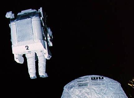
“41-B ONBOARD SCENE OF EVA---Astronaut Robert L. Stewart, 41-B mission specialist, uses hand controls on his nitrogen-propelled backpack, called a manned maneuvering unit, to move above the cargo bay of the Earth-orbiting Space Shuttle Challenger. In the midst of darkness, Stewart is only one of three visible objects in the photo. A TV camera is lower right edge and the shield for the Westar VI satellite is nearby.”
This is such a unique & cool view. Per/at the following link, it's supposedly taken by the fixed camera in Bruce McCandless's helmet. Although taken by McCandless, since the perspective is too low to have been taken from the aft-facing flight deck windows, it possibly was by the fixed camera, However, the fixed camera is attached to the MMU itself. The video camera is the one in the helmet.
The fixed still camera is quite conspicuous & easily identifiable. In this photograph of MMU no. 2, it's the appendage sticking out from the upper left corner of it.
I assume the following is a raw image, unless a nearby unreported UFO was emitting the green glow:
nara.getarchive.net/media/41b-21-850-sts-41b-view-of-astr...
Credit: NARA website
Possibly the only correct statement at the above link is "Stewart flies the MMU down the payload bay to the Shuttle Pallet Satellite (SPAS) 01A."
Regardless, interesting trivia, paraphrased from the Astronautix website, at:
www.astronautix.com/s/sts-41-b.html
The German-built SPAS-01A, first flown on STS-7, became the first satellite refurbished & flown again. Unfortunately, it remained in the payload bay due to an electrical problem with the Remote Manipulator System (RMS).
Better, although low resolution:
www.astronautix.com/graphics/1/10061777.jpg
Credit: Astronautix website
Would both Astronauts be wearing their respective MMUs simultaneously during the same EVA? I seriously doubt it...but who knows. If one seriously malfunctioned, I suppose you’d need the guy with the good one equally ‘suited up’ to render aid.
“The world’s first view of the Earth taken by a spacecraft from the vicinity of the Moon. The photo was transmitted to Earth by the United States Lunar Orbiter 1 and received at the NASA tracking station at Robledo De Chavela near Madrid, Spain. This crescent of the Earth was photographed August 23, at 16:35 GMT when the spacecraft was on its 16th orbit and just about to pass behind the Moon. This is the view the astronauts will have when they come around the backside of the moon and face the Earth. The Earth is shown on the left of the Photo with the U.S. east coast in the upper left, southern Europe toward the dark or night side of Earth, and Antarctica at the bottom of Earth crescent. The surface of the Moon is shown on the right side of the photo. Re-enhanced photograph - October 24, 1966.”
This photo is part of the historic & iconic ‘first photo of Earth from the moon’ panorama, comprising the middle ~third of it. The first photograph linked to below is NASA photo ID no. 66-H-1379, it being the right/upper (depending upon orientation) ~third of that panorama. Could that mean there’s a 66-H-1381…it being the left/lower ~third? I doubt it, that would be logical/make too much sense.
The conspicuous ‘dark’ crater to the right is Khvol’son. Hilbert E is at the lower right of the image. A portion of Hilbert Crater & its multiple other satellite craters are spread across the surface to the left of Hilbert E.
See also:
www.lpi.usra.edu/resources/lunarorbiter/frame/?1102
Specifically:
www.lpi.usra.edu/resources/lunarorbiter/images/preview/11...
Both above credit: LPI website
The Vienna Giant Ferris Wheel (Wiener Riesenrad) isn't merely an amusement ride; it's a voyage through history with a touch of cinematic allure. Soaring gracefully to an impressive height of 64.75 meters, it stands proudly as an iconic emblem of Vienna's skyline. Stepping into one of its historic cabins instantly transports you to a bygone era. These charming cabins, each boasting a spacious 7.3-meter diameter, have borne witness to over a century of history while retaining their original charm. Constructed in 1897 to celebrate Emperor Franz Joseph I's Golden Jubilee, the Ferris Wheel itself stands as a marvel of engineering. Its silver screen debut in the 1949 classic "The Third Man" catapulted the Ferris Wheel to cinematic stardom, forever etching its silhouette in the annals of film history – The Prater, Vienna, Austria
The Montjuïc Communications Tower, also known as the Torre Calatrava, is a striking architectural structure located in the Olympic Park of Montjuïc in Barcelona, Spain. Designed by the renowned architect Santiago Calatrava, the tower was constructed between 1989 and 1992. Its futuristic design, representing an athlete holding the Olympic flame, has become an iconic symbol of the city. The tower also serves as a functional element, transmitting television coverage of the 1992 Olympic Games.
Grumman Aircraft Engineering Corporation (GAEC) print/artwork, ca. 1967, depicting Lunar Module powered descent just prior to touchdown on the lunar surface.
GAEC + LEM/LM + artist's concept pretty much = Craig Kavafes. However, his signature is not to be found, unlike the vast majority of his other works, even early on. Somehow though, it doesn't quite look to be by his hand. Idk. Whoever it is, it’s awesome.
11” x 14”.
“PLT. 5 CLOSE UP OF LEM AREA”
More importantly, hand-printed on the verso:
“X – PERRY’S ORIGINAL FLT TEST HANGAR.
FURTHER TO LEFT WAS PERRY’S NEW HANGAR (WITH SMALL ANTENNA TOWER IN CENTER).
THE LM WAS LATER BUILT IN THESE HANGARS WITH ADDED SURROUNDING FACILITIES.”
So, the above serves not only as wonderful ‘insider’ information pertaining to GAEC’s Bethpage facility, but also as a ‘key’ with regard to the red ink “X” and arrow (along with “PERRY’S HGRS”) written in the white border on the obverse.
Per the discussion at the following collectSPACE thread, the “new hangar” referenced above would’ve (I suppose) made it the primary Lunar Excursion Module/Lunar Module (LEM/LM) assembly building, containing a clean room where three of them could be simultaneously assembled.
www.collectspace.com/ubb/Forum41/HTML/000122.html
I really should’ve purchased at least one of the two LM books referenced in the thread.
However - to me - the $64K question is what the heck is/are “Perry’s Hangar(s)”? The annotation (arrow) on the photograph seems to point to the slightly lower profile building to the right of & adjacent to the "LEM Assembly, Installation and Test" building (with the antenna tower).
A 5,000 sq. ft section of it (nearest the aforementioned building) consists of a clean room for exclusive LEM use pertaining to RCS & ECS.
Could it refer to Perry L. Gardner? There are multiple GAEC-associated documents in/of which he was an integral part. His son even has a wonderful site devoted to his journals. Despite that & meaning no disrespect, he doesn’t appear to be ‘historic’ enough, or even old enough for that matter.
The ONLY place that actually references “Perry’s Hangar” is, as one might expect, at the “Grumman Memorial Park” website, which unfortunately appears to be static as of 2012. I’m actually surprised it’s still up. But all it has is one low resolution photo, taken inside the hangar, apparently in 1950…with no context, no write-up, nothing.
So, there's some sort of obscure, poorly documented historical significance, or so I'd think. I mean, you don't name something after/for an individual, formally or informally, unless there's something that merited it.
I foolishly sent an email to their contact address, which I’m sure was an exercise in futility. I’ve also reached out to the Grumman Retiree Club, which I've done a couple of times in the past regarding some of my other photos. Crickets then & no reason to expect anything different now. Maybe I'll try the Cradle of Aviation folks. Eventually, someone's got to respond, to something, anything, right?
Nah, I doubt it, so…I'm tapping out. That's about it with regard to Perry’s Hangar. ¯\_(ツ)_/¯
I’d also like to know who made the annotations on the photo.
Finally, look at the place…a textbook example of never judging a book by its cover. It looks like…I dunno…a run-of-the-mill machine shop. And kind of grimy looking at that. The outward appearance belies the engineering magic that went on inside.
I opted for a 1200 dpi scan on this, ignorantly hoping to maybe resolve some identifiable LEM component(s) on the grounds. I haven’t, but other peripheral things can be seen…to include horses grazing in the grassy field on the left. And, the trailer at the near end of the larger angled building comprising the "Cold Flow Test Site"...you can make out "LIQUID CARBONIC / GENERAL DYNAMICS", written on what looks like its outer gas cylinders. Two more such trailers may be near the far end of the smaller Cold Flow Test Site building. The Liquid Carbonic Company produced industrial gasses, including oxygen & acetylene, amongst others, to include liquid oxygen distribution. On the background oward the upper left is a Westinghouse Electric building/facility. Possibly located there as a subcontractor? Or totally unrelated? Since this whole area appears to be zoned for light industrial usage. Just to the left of Plant no. 25, the Engineering Center, which is the large rectangularly partitioned building in the background, the angled Quonset hut-like structure is a wind tunnel. Who knew?!
Finally, check out the two possible GAEC execs shooting the breeze in what looks to be an Alfa Romeo Spider [WRONG: see/read corrected identification below], just inside the side entrance gate at the bottom of the photo. Along those lines, look at the smorgasbord of other vintage automobiles...it's like an open-air museum.
Also outstanding:
yesterdaysamerica.com/remembering-the-apollo-program/
Credit: "Yesterday's America" website
I hope this happened:
news.northropgrumman.com/news/releases/northrop-grumman-s...
Credit: Northrop Grumman website
Finally, can you believe it?! But hey, at least they’re still standing…I think/hope:
The Golden Gate Bridge's north tower rises majestically through the twilight, its International Orange paint glowing warmly under artificial lighting while the deep blue hour sky provides dramatic backdrop. Photographed from the rocky shoreline near Fort Point on the San Francisco side, this perspective captures the bridge at its most atmospheric—that fleeting moment when day surrenders to night and the iconic structure transforms into a beacon of light.
The bridge's distinctive Art Deco tower stands tall against Marin Headlands silhouetted in the distance, its steel lattice framework illuminated by powerful lights mounted at the base and along the span. The red aviation warning light at the tower's peak blinks as a safety measure for aircraft, while the decorative lighting traces the suspension cables and vertical supports. This lighting design, implemented in the 1980s, ensures the bridge remains visible and photogenic after dark while honoring its status as one of the world's most recognizable structures.
Fort Point area facilities cluster at the tower's base—the historic fortification, visitor amenities, and access roads all bathed in warm artificial light that creates a glowing pool against the darkening landscape. The juxtaposition of military history and engineering marvel is evident here, where a Civil War-era brick fort sits in the shadow of the 1937 suspension bridge that chief engineer Joseph Strauss designed to span directly over it rather than requiring its demolition.
The rocky foreground typical of San Francisco's rugged coastline frames the composition, while the calm bay waters reflect the bridge's illumination. Marin County's hills rise across the strait, their dark forms punctuated by scattered lights from Sausalito and other North Bay communities. The atmospheric conditions—likely some fog or marine layer evident in the soft focus of distant hills—create that quintessential Golden Gate Bridge aesthetic where the structure emerges from and disappears into California's coastal weather.
The deep blue twilight sky shows perfect timing for this type of photography. Too early and the artificial lights wouldn't register dramatically; too late and the sky would be completely black, losing the color gradation that provides context and mood. This blue hour window—perhaps fifteen minutes when the light balance is just right—requires planning and patience but yields images that capture the bridge's romantic, almost ethereal quality that has made it a global icon.
“GRUMMAN AIRCRAFT ENGINEERING CORP., BETHPAGE, NEW YORK
LM MANUFACTURING----Apollo Lunar Module-5 in Final Assembly Area during demate procedures.”
I believe those are Chinese characters stamped on the verso. Makes me wonder where this has been, along with resisting the urge to defecate on it.
“LUNAR MODULE -- Full scale mock up of the lunar module used at the Manned Spacecraft Center for equipment tests. Jack D. Mays, test subject from Crew Systems Division, MSC, stands on top of the LM with hand-held prototype of television camera. He wears thermal over garment, a protective suit, over the International Latex Corp., space suit.”
Mr. Mays was basically the non-Astronaut 'face' of the Apollo program's outdoor terrestrial/Terran Extravehicular Activity, testing, assessing/evaluating, etc. lunar space suit designs/configurations & associated lunar surface tasks, during their development.
www.collectspace.com/ubb/Forum38/HTML/002223.html
Credit: collectSPACE website
historycollection.jsc.nasa.gov/JSCHistoryPortal/history/o...
Note the developmental/precursor “Snoopy Cap” worn by Mr. Mays.
Note also the rendezvous radar antenna. Both it’s interesting rotational/gimbaling capacity, and the fact that it’s pointing off to the side. To my knowledge, the final configuration only slewed up & down.
Maybe it was installed incorrectly? 😉
See also:
Credit: Internet Archive website
“This picture was taken on March 4, 1979 at 2:30 A.M. PST by Voyager 1 from a distance of 2.6 million kilometers (1.6 million miles). Ganymede is Jupiter's largest satellite with a radius of about 2600 kilometers, about 1.5 times that of our Moon. Ganymede has a bulk density of only approximately 2.0 g/cc almost half that of the Moon. Therefore, Ganymede is probably composed of a mixture of rock and ice. The features here, the large dark regions, in the northeast quadrant, and the white spots, resemble features found on the Moon, mare and impact craters respectively. The long white filaments resemble rays associated with impacts on the lunar surface. The various colors of different regions probably represent differing surface materials. There are several dots on the picture of single color (blue, green, and orange) which are the result of markings on the camera used for pointing determinations and are not physical markings. JPL manages and controls the Voyager project for NASA's Office of Space Science.”
The photograph is from the collection of Eric Burgess.
In color with the above, at:
photojournal.jpl.nasa.gov/catalog/PIA00353
Also:
“After its close flyby of Io, Voyager 1 headed for Ganymede, the largest of the Galilean satellites. This global view of Ganymede, taken on March 4 at a range of 2.6 million kilometers, shows features as small as 50 kilometers. At the time, Voyager scientists speculated that the numerous white spots were impact craters, surrounded in some cases by icy ejecta blankets splashed onto the surrounding surface. However, many narrow white streaks, especially those in the lower left quadrant, promised new and exciting geological features on this satellite.”
Above is the caption associated with the color image on page 79, of NASA SP-439: “Voyage To Jupiter”, 1980, written by David Morrison & Jane Samz.
“This artist's concept of the Voyager spacecraft with its antenna pointing to Earth. The identical Voyager spacecraft are three-axis stabilized systems that use celestial or gyro referenced attitude control to maintain pointing of the high-gain antennas toward Earth. The prime mission science payload consisted of 10 instruments (11 investigations including radio science). Only five investigator teams are still supported, though data are collected for two additional instruments.”
The above & image at/from:
photojournal.jpl.nasa.gov/catalog/PIA04495
Credit: JPL Photojournal website
A reverse image search of this photograph reveals that everybody - I mean EVERYBODY - and their brother, mother, second-cousin, the neighbor across the street…you name it, has posted this. Even NASA.
From the estate of Eric Burgess and possibly featured as “figure 4-8(a)” in one of his many books.
Based on the photo ID number and its overall gorgeous appearance, possibly by Ken Hodges.
Illuminated dramatically under the sodium glow of streetlights, this photograph captures the massive, enduring structure of a historic warehouse at San Francisco's Pier 70. The scene is set early morning, lending the industrial architecture a powerful, almost theatrical presence. The building's core material is a warm, aged red-orange brick, which has been spotlit to emphasize its rough, textured surface and the vertical lines formed by the pilasters.
The most dominant feature of the façade is the series of monumental, repeating arched windows. These are not small openings, but enormous semi-circular bays filled with meticulous black metal gridwork, showcasing the original engineering necessary to light the massive interior workshops. The grid structure, visible against the illuminated white walls inside, creates a sharp, graphic contrast to the soft texture of the exterior brick. The arched form is repeated down the length of the building, creating an impressive sense of scale and rhythmic pattern.
The lighting plays a crucial role in the composition. Warm light spills out from small ground-level entrances and is cast downward by overhead streetlamps, creating deep shadows that heighten the building's three-dimensional relief. The empty asphalt street in the foreground features clearly marked white lines indicating "PERMIT PARKING ONLY," grounding the historic scene in the present-day reality of the busy urban district. The entire structure feels like a powerful, solid remnant of the city's industrial past, beautifully preserved and given new life. This early morning view transforms the utilitarian factory wall into a magnificent display of structural resilience and historic brick artistry.
An excellent photograph of the M-5 LEM mockup at Grumman Aircraft Engineering Corporation’s (GAEC) Bethpage, N. Y. plant.
Note the laid out components, photos, graphics, schematics, displays, etc. of LEM systems. I assume for VIP/NASA visitations/presentations in conjunction with their attendance at testing, evaluations, meetings, conferences, etc.
And that repellent flooring that was EVERYWHERE during my childhood. As if being fugly wasn’t enough:
inspectapedia.com/hazmat/Asbestos_Floor_Tile_Color_Guide....
Credit: InspectAPedia website
in madrid, where the "cuatro torres" stretch, two giants reach for the sky, nearly piercing the cotton-like clouds above. glass surfaces mirror the ambition of a city, reflecting fragments of blue and white in a spectacle of modernity. there's a conversation between earth and heaven here, a visual poetry of aspiration, where human ingenuity meets the artistry of the skies. the towers, like beacons of progress, stand as sentinels at the threshold of the clouds, their tips disappearing into a dreamscape where the boundaries of reality seem to blur into the ether.
I'm pretty sure this is another unicorn. An original ca. 1966/67 Lunar Orbiter I panoramic photograph measuring 3’ 5.5” x 9’ 9.75”.
Yes, it’s nearly 10 feet long!
The earth itself is 15” in diameter!
I was informed by the gentleman I obtained it from, who lives/lived in Seattle, Washington, that it came from the estate of a Boeing employee there, who stated that it was originally tacked to a wall, possibly of a hallway, at the Boeing Missile Production Center, also in Seattle, where the Lunar Orbiter spacecraft were assembled.
I have no doubts regarding the validity of the above assertion. There are in fact ‘vintage’ tack holes in the corners. Although the verso bears no watermark, it is definitely some sort of photographic paper, with a very slight, appealing actually, sepia tone. Although, it's not as prominent as this photograph would suggest. However, reducing the saturation to accurately reflect the photograph makes the flooring look suspiciously colorless. You're just going to have to take my word for it. The two visible plexiglass panels are of course to keep the photograph flat. Lighting was oblique natural under somewhat overcast conditions.
It's really in remarkable condition.
Note how the following 'full' version extends the scene further to the left:
nssdc.gsfc.nasa.gov/imgcat/html/object_page/lo1_h102_123....
Credit: NSSDCA website
This is the only other reference to a large/larger version of this amazing photograph that I’ve seen:
www.spaceref.com/news/viewnews.html?id=1496
Credit: SPACEREF website
Credit: MOONVIEWS: Official website of the Lunar Orbiter Image Recovery Project (LOIRP)
twitter.com/NASAhistory/status/1066783585171111937
Credit: NASA History Office/Twitter
www.nasa.gov/topics/moonmars/features/LOIRP/EL-2002000508...
The above query was from 2011, so I’m pretty sure Mr. Cowing has found one by now. 😉
Looks to be another print from the same ‘production run’, also with the white border & I think the same size:
history.nasa.gov/SP-4308/ch10.htm
Last, but not least:
archive.org/details/loirpimagegallery
Credit: Internet Archive website...I really need to donate to their superior efforts.
“In this picture the Pioneer 11 spacecraft is entering the thermal-vacuum chamber at TRW Space Systems Division in Redondo Beach, Ca.
The dish antenna focuses the 8-watt radio on the Earth almost one billion miles away. The spacecraft weighed at launch 570 lbs. This included 65 lbs. of scientific instruments. Pioneer 11 carries 11 onboard scientific instruments.
The Pioneer 11 spacecraft will make its closest approach to Saturn on September 1, and one of its moons, Titan on September 2.
The Pioneer Saturn project is managed by NASA’s Ames Research Center, Mountain View, Ca. The spacecraft was built by TRW.”
Awkwardly written, oddly only referencing the Saturn approach, with no mention of the year for that. But by golly it’ll be in ‘some’ September.
At least it indirectly brought attention to the puny power of the radio, the mind-boggling distance it had to transmit with that power, and the remarkably light weight of the spacecraft.
“This photo of a bulletin board shows some of the clippings taken from leading U. S. newspapers during and shortly after the Lunar Orbiter I mission. Stories of the mission were given prominent play in such leading publications as the Los Angeles Times, The New York Times, Christian Science Monitor, the Los Angeles Herald Examiner, the Pasadena Independent, Life magazine, Time and Newsweek magazines.”
The bulletin board was likely at Boeing’s Seattle, Washington headquarters.
“APOLLO 10 ROLL OUT----Aerial view at Launch Complex
Aerial view at Launch Complex 39, Kennedy Space Center, showing a closeup of the 363-ft. tall Apollo 10 (Spacecraft 106/Lunar Module-4/Saturn 505) space vehicle on its way to Pad B. The Saturn V stack and its mobile launch tower are atop a huge crawler-transporter. The Apollo 10 flight is scheduled as a lunar orbit mission. The Apollo 10 crew will be Astronauts Thomas P. Stafford, commander; John W. Young, command module pilot; and Eugene A. Cernan, lunar module pilot.”
The original “mega rocket”.
A stunning image despite the obvious yellowing, low contrast & creasing of both top corners into the image (not visible in either scan).
“Artist’s concept of lunar landing research vehicle under study for NASA.”
Above per the NASA-appropriated issuance of the photo. Not a whole lot of calories burned on that caption, eh?
A little ironic as well. What’s easily one of the more vivid, creative, almost surrealistic early artist’s concepts pertaining to the Apollo program - and that’s the best that the crack NASA photo braintrust professionals could muster??? Pertaining to one of the most exotic & complex training vehicles of the Apollo Program. WTF, over?
Counterintuitively, the artist's name appears to have been intentionally omitted/cropped,...from this original & official Bell Aerosystems photo, yet retained in the NASA version. WTF deux!
Maybe Carl was a little eccentric, a loose cannon, irreverent, possibly an asshole, and/or pissed off someone in management…and thus png’d.
Even it’s conspicuous omission from the following authoritative document. Befuddling:
www.hq.nasa.gov/alsj/LLRV_Monograph.pdf
Credit: ALSJ website
See also:
e05.code.blog/2021/06/15/s-64-18126/
Both above credit: “numbers station” blog (Lots & lot & lots of wonderful images here…I highly advise you to look around further within.)
The source for the color version above:
www.afmc.af.mil/News/Article-Display/Article/1898049/hist...
Credit: Air Force Materiel Command (AFMC) website
Also seen here, along with some other remarkable works:
www.popsci.com/story/space/nasa-art-illustrations/
Credit: Popular Science website
Last, but NOT LEAST:
Mr. Zoschke participated in the BATTLE OF THE BULGE!!!
I KNEW there was something more that I liked about him:
Credit: Buffalo Architecture and History website (which thankfully will remain online in perpetuity)!!!
If any of the above even mildly piqued your interest in either artist's concepts, space flight, Carl Zoschke, or any combination thereof, purchase the following book. Seriously:
"The Art of NASA: The Illustrations That Sold the Missions"
Written by Piers Bizony, with additional exhaustive, conscientious, thorough, earnest & impeccable research by Mike Acs.
Wait, if you've got $35 to spare, you really need to put it towards supporting a local NON-KILL shelter or some other organization that's committed to helping, saving/rescuing animals. SERIOUSLY.
Finally, the "T. L. Branigan" referenced on the verso was, during this time, the editor of the "TRW Space Log", a monthly publication put out by the company to highlight their accomplishments, efforts, etc. In his capacity, Thomas L. Branigan worked out of the Kennedy Space Center.
Finally, additional good LLRV reading:
thehighfrontier.blog/2016/11/13/less-than-gravity-the-lun...
Credit: Chris B. Petty/"The High Frontier" blog website
“Washington, D.C., -- The world’s first view of the Earth taken by a spacecraft from the vicinity of the Moon. The photo was transmitted to Earth by the United States Lunar Orbiter I and received at the NASA tracking station at Robledo de Chavela near Madrid, Spain. This crescent of the Earth was photographed August 23, at 16:35 GMT when the spacecraft was on its 16th orbit and just about to pass behind the Moon. This is the view the astronauts will have when they come around the backside of the Moon and face the Earth. The Earth is shown on the left of the photo with the U.S. east coast in the upper left, southern Europe toward the dark or night side of Earth, and Antarctica at the bottom of Earth crescent. The surface of the Moon is shown on the right side of the photo.”
www.space.com/12707-earth-photo-moon-nasa-lunar-orbiter-1...
Credit: Space.com website
nssdc.gsfc.nasa.gov/imgcat/html/object_page/lo1_h102_123....
Also…really cool:
www.planetary.org/explore/space-topics/earth/pics-of-eart...
Credit: The Planetary Society website
And I'm sure plenty of others.
“This dramatic view of the crescents of Neptune and Triton was acquired by Voyager 2 approximately 3 days, 6 and one-half hours after its closest approach to Neptune. The spacecraft is now plunging southward at an angle of 48 degrees to the plane of the ecliptic. This direction, combined with the current season of southern summer in the Neptune system, gives this picture its unique geometry. The spacecraft was at a distance of 4.86 million kilometers (3 million miles) from Neptune when these images were shuttered so the smallest detail discernible is approximately 90 kilometers (56 miles). Color was produced using images taken through the narrow-angle camera's clear, orange and green filters. Neptune does not appear as blue from this viewpoint because the forward scattering nature of its atmosphere is more important than its absorption of red light at this high phase angle (134 degrees). The Voyager Mission is conducted by JPL for NASA's Office of Space Science and Applications.”
Odd that the image is oriented differently, but accounted for in the otherwise identical caption:
photojournal.jpl.nasa.gov/catalog/PIA02215
Credit: Jet Propulsion Laboratory Photojournal website
Irrespective of the current owner, impeccable provenance: Mr. Eric Burgess.
I wonder if this actual photograph served as the source for Figure 6-22 of the esteemed author’s book, “Far Encounter: The Neptune System”. Even if not, an honor.
“In the Vehicle Assembly Building (VAB), the orbiter Endeavour is hoisted to a vertical position for lifting over the VAB’s 190-foot-high interior framing. The space plane is turned sideways to fit throught the interior opening, then lowered for mating with the external tank/solid rocket booster assembly resting atop the mobile launcher platform in VAB High Bay 3. Rollout to Launch Pad 39B is scheduled in about five days, followed by launch of Mission STS-47 in September.”
Yes, “throught”…I didn’t feel like correcting it, like I all too often ‘have’ to. However, it’s a clever photo.
That was quick! And, a rarity of consideration, courtesy & intelligence…Reddit user “ImageExact5491” actually provided attribution to me!
An exceedingly rare & refreshing exception!
My sincerest thanks:
www.reddit.com/r/spaceshuttle/comments/1smhwr2/photo_of_t...
It’s well worth checking out his/her other postings:
Despite the apparent multiple-choice nature of the affixed caption, based on the 8/17/92 date on the caption & loosely, on other sort of similarly numbered photos – I’m going with “b”/“no. 2”.
Obviously, meant for internal consumption, so I’ll cut the NASA photo ‘professionals’ some undeserved slack.
So, I’m going to assume the following applies, regardless of choice:
“VAB/OMEF OPERATIONS.”
With that, my final answer, at least for now, is:
“STS-47. OV-105. BEFORE MATED TO STACK.”
Finally, “CUSTOMER EXPOSED FILM-D’ARCANGELO” means…what? Mr./Ms. D’Arcangelo? Was he/she the photographer? If so, representing/working for/contracted by…the “customer”? Rockwell Int'l/Rocketdyne maybe, based on the “VAB/OMEF” nomenclature in the caption? BTW, there’s very little available on the OMEF, which I’m guessing was located within the VAB & possible predecessor to the Space Shuttle Main Engine Processing Facility (SSMEPF), which appears to have been located within/adjacent(?) to OPF-3. Whatever…close enough.
All that really matters is that it’s a damned good photograph of space flight stuff.
I've forgotten why, but I think these photographs support my identification:
georgesrockets.com/GRP/Scale/ShuttleData/HTMLshuttlepics/...
Credit: George Gassaway's wonderful site, "George's Rocketry Pages" website. No longer maintained, it will mark another sad day when it is no longer available, which I'm sure is sooner rather than later.
“This image of Neptune's satellite 1989N1 was obtained on Aug. 25, 1989 from a range of 146,000 kilometers (91,000 miles). The resolution is about 2.7 kilometers (1.7 miles) per line pair. The satellite, seen here about half illuminated, has an average radius of some 200 kilometers (120 miles). It is dark (albedo 6 percent) and spectrally grey. Hints of crater-like forms and groove-like lineations can be discerned. The apparent graininess of the image is caused by the short exposure necessary to avoid significant smear. The Voyager Mission is conducted by JPL for NASA's Office of Space Science and Applications.”
photojournal.jpl.nasa.gov/catalog/PIA00062
Credit: JPL Photojournal website
Being from the estate of Eric Burgess, the photograph was sourced for ‘Figure 5-15’, page 111, in his book “FAR ENCOUNTER – THE NEPTUNE SYSTEM”, with the following caption/description:
“This image of 1989N1 was obtained from a range of 91,000 miles (146,000 km). The satellite is half illuminated. There are hints of many craters and grove-like lineaments. What appears to be a huge crater with a diameter of 90 miles (150 km) mars the top part of the terminator region (NASA/JPL)”
The above, with the image (of the scanned book) is available at:
archive.org/details/farencounternept00burg/page/110/mode/2up
Credit: Internet Archive website (account required to view). Regardless, an account is HIGHLY RECOMMENDED, there’s no obligation and you WILL NOT regret it!)
1989N1 was later named ‘Proteus’ on September 16, 1989. The subsequent caption associated with that name, but applied to the same image:
“Proteus is the second largest moon of Neptune behind the mysterious Triton. Proteus was discovered only in 1989 by the Voyager 2 spacecraft. This is unusual since Neptune has a smaller moon - Nereid - which was discovered 33 years earlier from Earth. The reason Proteus was not discovered sooner is that its surface is very dark and it orbits much closer to Neptune. Proteus has an odd box-like shape and were it even slightly more massive, its own gravity would cause it to reform itself into a sphere.
Original NASA caption: This image of Neptune's satellite 1989N1 was obtained on Aug. 25, 1989 from a range of 146,000 kilometers (91,000 miles). The resolution is about 2.7 kilometers (1.7 miles) per line pair.
The satellite, seen here about half illuminated, has an average radius of some 200 kilometers (120 miles). It is dark (albedo 6 percent) and spectrally grey. Hints of crater-like forms and groove-like lineations can be discerned. The apparent graininess of the image is caused by the short exposure necessary to avoid significant smear.”
Above at/from:
commons.wikimedia.org/wiki/File:Proteus_(Voyager_2).jpg
Credit: Wikimedia Commons
Way more than I expected to find regarding 1989N1/Proteus. A few being:
en.wikipedia.org/wiki/Proteus_(moon)
Credit: Wikipedia
astro.if.ufrgs.br/solar/proteus.htm
Credit: UFRGS (Federal University of Rio Grande do Sul) website
“Note the enormous impact crater, the result of a powerful collision that almost tore Proteus apart 4 billion years ago. According to some, that impact would have produced a large cloud of debris, some of which spiraled away into space, and some of which might have formed the tiny moon Hippocamp.
The above paraphrased from:
www.latimes.com/science/sciencenow/la-sci-sn-new-neptune-...
Credit: Los Angeles Times online website
Finally, the image at the far right would appear to be a state-of-art processed version of my posted photo, which seems to resolve the 'massive crater' into multiple overlapping smaller impact craters:
twitter.com/tedstryk/status/963538615816081408
pbs.twimg.com/media/DV8s-dXX4AAa4L4?format=jpg&name=9...
Both above credit: Ted Stryk/Twitter
"At about 100 meters from the cargo bay of the space shuttle Challenger, Bruce McCandless II was further out than anyone had ever been before. Guided by a Manned Maneuvering Unit (MMU), astronaut McCandless, pictured above, was floating free in space. McCandless and fellow NASA astronaut Robert Stewart were the first to experience such an "untethered space walk" during Space Shuttle mission 41-B in 1984. The MMU works by shooting jets of nitrogen and has since been used to help deploy and retrieve satellites. With a mass over 140 kilograms, an MMU is heavy on Earth, but, like everything, is weightless when drifting in orbit. The MMU was replaced with the SAFER backpack propulsion unit."
Above at/from:
commons.wikimedia.org/wiki/File:Astronaut-in-space.jpg
Credit: Wikimedia Commons
Superior to the mediocre smorgasbord of NASA descriptions. Frankly, commencing in earnest some time during the 70’s, "official" NASA captions & descriptions pretty much suck, grammatically and in content, substance & accuracy. As evidenced by the following. And these are mild compared to many others:
Caption no. 1, at THE NASA image website:
“Astronaut Bruce McCandless II, 41-B mission specialist, reaches a maximum distance from the Challenger before reversing direction his manned maneuvering unit (MMU) and returning to the Challenger. A fellow crewmember inside the vehicle's cabin took this photograph with a 70mm camera. The untethered EVA marked the first such experience for astronauts.”
At:
images.nasa.gov/details-S84-27031
Caption no. 2, at a defunct NASA website:
“Astronaut Bruce McCandless, II, mission specialist, participates in a extravehicular activity (EVA), a few meters away from the cabin of the shuttle Challenger. McCandless approaches his maximum distance from the Challenger. He is framed by the blackness of space and below him a cloudy earth. He is floating without tethers connecting him to the shuttle.”
At:
science.ksc.nasa.gov/mirrors/images/images/pao/STS41B/100...
“Mariner 9 spacecraft showing some of instrumentation and scan platform with cameras pointing obliquely downward.”
Above hand-annotated (in cursive!) on the verso. I think written by a knowledgeable JPL employee…refreshing.
Also, per the caption of the equivalent NASA-numbered version, dated April 30, 1971:
“The Mariner Mars 1971 spacecraft is a Mars orbiter which is fully attitude stabilized using the Sun and the star Canopus as the basic attitude references. The spacecraft’s basic structure is a 40-pound, 8 sided magnesium framework with eight electronic compartments. The electronic assemblies fastened within the compartments provide structural support to the spacecraft. The weight of the spacecraft is approximately 2200 pounds. The launch vehicle/spacecraft upper adapter weight is about 72 pounds. The spacecraft measures 9 feet from the separation plane to the top of the low-gain antenna and has a burn-out weight of approximately 1190 pounds. Its span is 22 feet 7-1/2 inches with the solar panels extended. The basic octagonal structure is 54-1/2 inches high. Four solar panels, each 84-1/2 inches long and 35-1/2 inches wide, are attached on outriggers to the octagon.”
“APOLLO 4 ON PAD AT DAWN----Early morning view of Pad A, Launch Complex 39, Kennedy Space Center, showing Apollo 4 (Spacecraft 017/Saturn 501) unmanned, earth-orbital space mission ready for launch. The huge 363-ft. tall Apollo/Saturn V space vehicle was launched at 7:00:01 a.m. (EST), November 9, 1967.”
By any standard, an absolutely stunning image.
About that moon though, specifically, it's placement...
Compare with the below linked photograph...
Did the clouds really move that little while the earth rotated that much? Even if so, shouldn't there be a larger delta between the relative azimuth of the moon in both images? Our orbed maiden appears to have only seemingly translated horizontally.
I'm pretty certain both photographs were taken from the exact same position.
Something ain't right here.
You know, the more I read about the never ending SLS woes and now raptor engine issues & costs, this remarkable creation should’ve never been abandoned.
“The Apollo 17 space vehicle was moved today from the Vehicle Assembly Building to complex 39’s Pad A. in preparation for its launch with Astronauts Eugene A. Cernan, Commander; Ronald A. Evans, Command Module Pilot; and Dr. Harrison H. “Jack” Schmitt, Lunar Module Pilot, on the sixth U.S. manned lunar landing mission on December, 1972.
Excellent weather for the rollout of humankind’s last mission to the lunar surface. The beautiful blue sky & distinct puffy clouds made for great aesthetics…not that the Saturn V needs any ‘enhancement’.
August 1972…damn, that was a LONG time ago.
“This crescent view of Jupiter was taken by Voyager 1 on March 24, 1979. This image was taken through three color filters and recombined to produce the color image. This photo was assembled from three black and white negatives by the Image Processing Lab at Jet Propulsion Laboratory. JPL manages and controls the Voyager project for NASA's Office of Space Science.”
The above and image, at:
photojournal.jpl.nasa.gov/catalog/PIA01324
Also:
“This image of Jupiter was taken looking back almost three weeks after the 5 March closest approach. The Great Red Spot can be seen at lower right. Three images were taken through different filters and combined to give this view. Voyager 1 was roughly 30 million km away when this image was taken. Jupiter is 71,492 km in diameter and north is at 12:00.”
And image, at:
nssdc.gsfc.nasa.gov/imgcat/html/object_page/vg1_ipl260668...
Credit: NSSDCA website
As with most anything pertaining to NASA photographic [fill in the blank] during the 1970’s & later, even the photographic paper, despite being KODAK, was IMHO, inferior. Possibly further exacerbated by being considered disposable, hence handled with minimal care/consideration.
So, I suppose the red-shift of the image, common in many vintage photographs, is the primary culprit for the gorgeous, rich & incorrect color.
A striking & surrealistic visual feast by Carl Zoschke, Bell Aerosystems’ amazing resident artist. Circa possibly 1961/62. Note the two smaller, canted, descent engines (firing), adjacent to the primary? engine of the Lunar Excursion Module. I’ve never seen that before.
I’m a little surprised this isn’t already somewhere on this image hosting 'service'. If it is, I haven’t found it, even using what I think are logical key word searches. If not, it’s about time then.
From/at:
www.afmc.af.mil/News/Article-Display/Article/1898049/hist...
Credit: Air Force Materiel Command (AFMC) website
Also seen here, along with some other remarkable works:
www.popsci.com/story/space/nasa-art-illustrations/
Credit: Popular Science website
A fantastic book, btw. Written by a superior, acknowledged & respected author. I can also vouch for the guy that provided additional research.
An unidentified test subject/possible astronaut is seen practicing ingress/egress using the M-5 Lunar Excursion Module (LEM) mockup at Grumman Aircraft Engineering Corporation’s Bethpage facility. The photograph may have been taken during/around the time of the October 5-9, 1964 NASA Inspection and Review of the all-metal mockup.
For the first time in the development & evolution of the LEM, the M-5 featured a ladder attached to the forward (+Z) primary strut of the landing gear. Precursor designs offered a rope, and subsequently, a ladder that was flush mounted - with the capability to pivot/extend the lower end outward - to Quadrant 1 of the descent stage. However, the Astronaut would still have to somehow translate from the LM porch over to the ladder. Possibly still with the aid of a rope? And how would the outward force necessary to ‘deploy’ the ladder be imparted? Who knows, I’ve come across very very little with any specific/detailed - hence useful - documentation that elaborated on rope/offset ladder employment.
Upon input from the Astronauts, the circular forward hatch was subsequently squared off to better facilitate egress/ingress while wearing bulky pressure suits & PLSS. Speaking of PLSSs; per another similar photo, the PLSS seen being worn here may have been operable. Just my guess…although I may be connecting dots that aren’t there. If not, oh well. And note the very early version Apollo pressure suit worn by the subject.
Finally, note also the display/exhibit-like venue set up around the LEM, from what looks like a DPS/LMDE on the floor to the left, with (I think) ascent stage bulkhead mockups? to the rear near the back wall, to the multiple mounted pictures?/diagrams?/artist’s concepts? on the right.
Oh yeah, check out what I assume to be CCTV cameras mounted above the LEM windows.
The substantial audience would seem to support this possibly being part of/associated with the ‘NASA Inspection and Review’ of the LEM design.
“NASA conducted a formal review of the LEM mockup M-5 at the Grumman factory. This inspection was intended to affirm that the M-5 configuration reflected all design requirements and to definitize the LEM configuration. Members of the Mockup Review Board were Chairman Owen E. Maynard, Chief, Systems Engineering Division, ASPO; R. W. Carbee, LEM Subsystem Project Engineer, Grumman; Maxime A. Faget, Assistant Director for Engineering and Development, MSC; Thomas J. Kelly, LEM Project Engineer, Grumman; Christopher C. Kraft, Jr. (represented by Sigurd A. Sjoberg), Assistant Director for Flight Operations, MSC; Owen G. Morris, Chief, Reliability and Quality Assurance Division, ASPO; William F. Rector III, LEM Project Officer, ASPO; and Donald K. Slayton, Assistant Director for Flight Crew Operations, MSC.
The astronauts' review was held on October 5 and 6. It included demonstrations of entering and getting out of the LEM, techniques for climbing and descending the ladder, and crew mobility inside the spacecraft. The general inspection was held on the 7th and the Review Board met on the 8th. Those attending the review used request for change (RFC) forms to propose spacecraft design alterations. Before submission to the Board, these requests were discussed by contractor personnel and NASA coordinators to assess their effect upon system design, interfaces, weight, and reliability.
The inspection categories were crew provisions; controls, displays, and lighting; the stabilization and control system and the guidance and navigation radar; electrical power; propulsion (ascent, descent, reaction control system, and pyrotechnics ; power generation cryogenic storage and fuel cell assemblies ; environmental control; communications and instrumentation; structures and landing gear; scientific equipment; and reliability and quality' control. A total of 148 RFCs were submitted. Most were aimed at enhancing the spacecraft's operational capability; considerable attention also was given to quality and reliability and to ground checkout of various systems. No major redesigns of the configuration were suggested.
As a result of this review, the Board recommended that Grumman take immediate action on those RFC's which it had approved. Further, the LEM contractor and MSC should promptly investigate those items which the Board had assigned for further study. On the basis of the revised M-5 configuration, Grumman could proceed with LEM development and qualification. This updated mockup would be the basis for tooling and fabrication of the initial hardware as well.
MSC, "Lunar Excursion Module, Project Apollo, Board Report for NASA Inspection and Review of M-5 Mockup Lunar Excursion Module, October 5-8, 1964," pp. 1-7, 10-27.”
www.apolloproject.com/sp-4009/asc-v3-04.htm
Credit: APOLLOPROJECT.com
The image, along with a useless & generic 'caption/description' is at the following link. However, the overall content is excellent:
www.hq.nasa.gov/office/pao/History/SP-4205/ch6-4.html
Surprisingly & most pleasantly, the following link still works:
www.longislandaerospacehistory.com/Select/LM/XXX-LM-PROJE...
Credit: Cradle of Aviation Museum website
Last, but NOT least, a wonderful article written by Bob Smyth (see Figure 1):
web.mit.edu/digitalapollo/Documents/Chapter8/setplem.pdf
Credit: MIT website
Oh yeah...this is awesome:
www.youtube.com/watch?v=RwHOW7bCfh4
Credit: SDASM Archives
Even more awesome, and speaking of Bob Smyth:
www.youtube.com/watch?v=6UuRCwsGugg&t=13s
Credit: "From the Vault of MIT"/YouTube
“December 12, 1996
A chain of impact craters on Callisto
P-48124
A portion of a chain of impact craters on Jupiter's moon Callisto is seen in this image taken by the Galileo spacecraft on November 4, 1996. This crater chain on Callisto is believed to result from the impact of a split object, similar to the fragments of Comet Shoemaker-Levy 9 which smashed into Jupiter's atmosphere in July of 1994. This high-resolution view, taken by Galileo's solid state imaging television camera during its third orbit around Jupiter, is of Callisto's northern hemisphere at 35 degrees north, 46 degrees west, and covers an area of about eight miles (13 kilometers) across. The smallest visible crater is about 140 yards (130 meters) across. The image was taken at a range of 974 miles (1,567 kilometers).
On a global scale, Callisto is heavily cratered, indicating the great age of its surface. At the scale of this image, it was anticipated that the surface would be heavily cratered as well; however, there is a surprising lack of small craters, suggesting that one or more processes have obliterated these and other small-scale features. For example, downslope movement of ice-rich debris could bury small craters. The bright slopes visible in this picture represent places where downslope movement has taken place, exposing fresh ice surfaces.
The Jet Propulsion Laboratory, Pasadena, CA, manages the mission for NASA's Office of Space Science, Washington, D.C. This image and other images and data received from Galileo are posted on the Galileo mission home page on the World Wide Web at www.jpl.nasa.gov/galileo. Background information and educational context for the images can be found at www.jpl.nasa.gov/galileo/sepo”
Above & image also at:
photojournal.jpl.nasa.gov/catalog/PIA00514
A mosaic of images that reveals the crater chain better:
photojournal.jpl.nasa.gov/catalog/PIA00549
Also, with others:
nssdc.gsfc.nasa.gov/photo_gallery/photogallery-callisto.html
Credit: NSSDCA website
And then there’s THIS, wow…what a chain:
photojournal.jpl.nasa.gov/catalog/PIA00581
All above credit: JPL Photojournal website
“In KSC’s Payload Hazardous Servicing Facility (PHSF), assembly is complete of the Cassini Trailbazer, a model of the Cassini spacecraft slated to embark on an interplanetary journey to Saturn in October 1997. The Trailblazer will be transferred to the launch pad at Launch Complex 40 on Cape Canaveral Air Force Station, where it will undergo a series of fit checks with pad interfaces and the Titan IV expendable vehicle that will launch it into space. Access checks to the spacecraft for both personnel and equipment also will be conducted, as well as validation of the spacecraft timelines and procedures that will be used once the actual Cassini spacecraft arrives next year. The Trailblazer is scheduled to spend about two weeks at Complex 40 before being transported back to the PHSF to undergo preparations for its return to the Jet Propulsion Laboratory (JPL) in California. JPL is managing the Cassini project for NASA and several international partners, including the European Space Agency (ESA), the Italian Space Agency (ASI) and several separate European academic and industrial contributors.”
See/read also:
www.nasa.gov/centers/kennedy/pdf/329124main_04.12.96.pdf
Who knew??? Did you??? I didn’t!!!
Cassini: First year eligible “Unmanned Spacecraft Hall of Fame” inductee…a no-brainer.
Easily a “Top 3” of all-time & arguably…No. 1.
“This image of Europa, smallest of Jupiter's four Galilean satellites, was acquired by Voyager 2 on July 9, 1979, from a range of 241,000 kilometers (150,600 miles). Europa, the brightest of the Galilean satellites, has a density slightly less than Io, suggesting it has a substantial quantity of water. Scientists previously speculated that the water must have cooled from the interior and formed a mantle of ice perhaps 100 kilometers (62 miles) thick. The complex patterns on its surface suggest that the icy surface was fractured, and that the cracks filled with dark material from below. Very few impact craters are visible on the surface, suggesting that active processes on the surface are still modifying Europa. The tectonic pattern seen on its surface differs drastically from the fault systems seen on Ganymede where pieces of the crust have moved relative to each other. On Europa, the crust evidently fractures but the pieces remain in roughly their original position.”
Above per the following, with what ‘may’ be a/the black & white version of this photograph, with greatly enhanced contrast:
photojournal.jpl.nasa.gov/catalog/PIA01503
Credit: JPL Photojournal website
The other color versions I’ve come across, although very similar & also acquired July 9, 1979, are of a different region of Europa.
Additionally, thanks to Galileo (the spacecraft), and since Thera & Thrace Maculae feature prominently in this photo:
photojournal.jpl.nasa.gov/catalog/PIA00875
Also credit: JPL Photojournal website
Hmm…Europa Clipper…might wanna reconsider that NASA/ESA. We destroy everything we touch. Might be wise to heed the following:
ALL THESE WORLDS ARE YOURS - EXCEPT EUROPA.
ATTEMPT NO LANDING THERE.
The Golden Gate Bridge glows orange against the predawn darkness, its iconic towers and suspension cables illuminated while fog wraps around the Marin Headlands beyond.
Photographed from Twin Peaks looking west, this panoramic view captures San Francisco in that liminal moment between night and day when the city's lights still sparkle but natural light begins painting the sky in subtle gradients of blue and pink.The bridge itself commands the middle distance, its distinctive International Orange color standing out even in low light thanks to the decorative lighting that traces its towers and cables. Those twin towers rising 746 feet above the water have become synonymous with San Francisco itself, perhaps the most photographed and recognizable bridge in the world.
Opened in 1937 after four years of construction, the Golden Gate Bridge was an engineering marvel that many said couldn't be built—spanning 4,200 feet across the strait connecting San Francisco Bay to the Pacific Ocean, withstanding powerful currents, deep water, and frequent fog.
The foreground reveals San Francisco's residential fabric spreading across the city's western neighborhoods. This elevated vantage from Twin Peaks—roughly 900 feet above sea level—allows you to see the gridded street pattern, the mix of housing types, and the tree canopy that softens the urban density. The Richmond and Sunset districts dominate this western side of the city, their orderly blocks of single-family homes, small apartment buildings, and neighborhood commercial corridors representing post-earthquake development and the city's mid-century suburban expansion within city limits.
Look at how the city lights create different patterns. Bright commercial zones—likely the Richmond District's Geary Boulevard and the Sunset's Irving Street—cut horizontal paths through residential areas where warmer, more diffuse lighting suggests homes and local businesses. The Presidio's darker areas on the left preserve the former military base's forest and open space, while Golden Gate Park's dark band running through the middle of the frame shows how that three-mile-long urban forest creates a natural break in the city's development pattern.
The atmospheric conditions are quintessentially San Francisco. That thick bank of fog sitting over the Marin Headlands and threatening to spill through the Golden Gate represents the marine layer that gives the Bay Area its temperate climate and famously unpredictable weather.
The bridge's towers emerge from the fog like sentinels, while the low cloud deck above creates a muted sky that will likely give way to sunshine or remain overcast depending on how that marine layer behaves over the next few hours.The bay waters beyond the bridge show as a dark band separating San Francisco from Marin County.
This strait has always been treacherous—strong tidal currents, cold water temperatures, and frequent fog made navigation challenging long before the bridge existed. Ships entering San Francisco Bay had to time their passage carefully, and countless vessels met disaster on the rocks.
The bridge transformed regional transportation, connecting San Francisco to the North Bay and beyond, enabling suburban development in Marin and Sonoma counties that fundamentally reshaped the region's geography.
From this elevated perspective, you can appreciate San Francisco's unique urban form. This is a city that refused to be limited by its hilly topography. Those neighborhoods spreading across the western slopes represent generations of San Franciscans who carved streets into steep hillsides, built homes on challenging lots, and created communities in every available space. The density is impressive—this is one of America's most densely populated cities—yet the scale remains human. Few high-rises interrupt the horizon, preserving view corridors and maintaining neighborhood character.
The lighting in this photograph creates layers of depth and atmosphere. The cool predawn sky gradates from darker blue overhead to lighter tones near the horizon, while the warm city lights provide contrast and detail in the foreground. The bridge's orange glow becomes the visual anchor, drawing the eye across the frame while the scattered lights of Marin communities beyond suggest the broader metropolitan region connected by this single span.
San Francisco's relationship with the Golden Gate Bridge is complicated. It's simultaneously the city's most beloved symbol and a barrier some never cross. The bridge connects but also divides—creating a psychological boundary between city and suburbs, between urban San Francisco and the less dense communities to the north.
For tourists, it's a must-see attraction. For locals, it's infrastructure—a commute route, a running path, a beloved but familiar landmark that becomes invisible through daily exposure until you see it like this, at dawn, and remember why people photograph it obsessively.
Based on the date stamped on the verso, the day after the flight/mission, the vehicle is likely Apollo 4, depicted during ascent, propelled by the single J-2 engine of the S-IVB stage.
Stylistically, and with the often-recurring numbering in the corner of the photo, this is likely another lost/forgotten? gem by Russell Arasmith. Although a slightly less polished, less detailed effort when compared to latter renderings. Possibly due to being early/earlier during Mr. Arasmith’s incredible career? And combined with maybe less available imagery to work with, this being the first launch of the Saturn V rocket.
Obviously one of a series, although a little odd that this phase of the flight would be labeled no. 1. I just need to ‘shut up’ & not look a gift-horse in the mouth…this is a win.
A full life:
www.dignitymemorial.com/obituaries/westminster-ca/russell...
Credit: Dignity Memorial website
I'm sure only a fraction:
www.nasa.gov/centers/marshall/history/arasmith-gallery.html
A wonderful peak, confirming my above statement:
d3eguztg5751m.cloudfront.net/as/assets-mem-com/cmi/7/7/9/...
&cropxunits=619&cropyunits=464&maxwidth=650)
Credit: The Arasmith Family/Dignity Memorial website
“SATURN SPACE VEHICLE LAUNCHING – This is an artist’s conception of the National Aeronautics and Space Administration advanced Saturn space vehicle at moment of launch from Cape Canaveral, Florida. The first stage is to be developed by The Boeing Company under the technical direction of the NASA Marshall Space Flight Center.
--Boeing Photo”
While I legitimately & rightfully tout the virtues of black & white photographs and illustrations, boy does this look damned good in color.
One of many stunning works by Boeing artist/illustrator Fred Takasumi.
Wouldn't you agree?
www.pinterest.es/pin/287948969910304990/
Credit: Pinterest/Chase Covello/Dan Beaumont Space Museum (Sadly, it seems Mr. Beaumont has removed the image from this photo hosting site.)
“STS-103 EVA VIEW --- Astronauts C. Michael Foale (left) and Claude Nicollier participate in the second of three STS-103 spacewalks to service the Hubble Space Telescope (HST). On this task they are replacing one of the telescope’s Fine Guidance Sensors (FGS). Nicollier, a European Space Agency (ESA) astronaut, is standing on the end of the remote manipulator system (RMS).”
Additionally, per the “HUBBLESITE” website:
“December 19-27, 1999
SPACE SHUTTLE: Discovery
Crew: Commander Curtis L. Brown, Pilot Scott J. Kelly, Payload Commander Steven L. Smith, Mission Specialists C. Michael Foale, John M. Grunsfield, Claude Nicollier and Jean-Francois Clervoy
NASA decided to split the Servicing Mission 3 (SM3) into two parts, SM3A and SM3B, after the third of Hubble’s six gyroscopes failed. (At that time, Hubble needed three gyroscopes to observe a celestial target.) The second part of the mission, SM3B, took place March 1–12, 2002.
On November 13, 1999, the Hubble Space Telescope was placed into safe mode after the failure of a fourth gyroscope. In safe mode Hubble could not observe targets, but its safety was preserved. This protective mode allows ground control of the telescope, but with only two gyros working, Hubble cannot be aimed with the precision necessary for scientific observations of the sky. Controllers closed the aperture door to protect the optics and aligned the spacecraft to ensure that Hubble’s solar panels would receive adequate power from the Sun.
In the first of the two-part mission, the most pressing task was the replacement of the gyroscopes. The crew, two of whom were Hubble repair veterans, replaced all six gyroscopes — as well as one of Hubble’s three Fine Guidance Sensors, which allow fine pointing and keep Hubble stable during observations, and a transmitter.
The astronauts also installed an advanced central computer, a digital data recorder, an electronics enhancement kit, battery improvement kits, and new outer layers of thermal protection. Hubble was as good as new.
Mission Highlights:
- Replacement of all three Rate Sensing Units (RSUs), each of which contains two gyroscopes
- Installation of new computer, 20 times faster with six times more memory than its predecessor
- Replacement of original reel-to-reel data recorder with digital Solid-State Recorder (SSR) which is faster, more reliable and can store 10 times as much data
- Replacement of no. 2 of 3 Fine Guidance Sensors (FGS) with refurbished unit
- Replacement of failed no. 2 of 2 S-Band Single Access Transmitter (SSAT) used to relay data to the ground
Installation six Voltage/Temperature Improvement Kits (VIKs) on wiring between Solar Arrays and each battery to control charging of Hubble's batteries
- Installation of Shell/Shield Replacement Fabric (SSRF) over the original Multi-Layer Insulation on Hubble’s forward shell and light shield to add thermal protection
- Installation of Handrail Covers around the handrails above the Fine Guidance Sensor bay to prevent possible contamination to the Aft Shroud area from flaking handrail paint
- Fit New Outer Blanket Layers (NOBLs) on equipment Bay 1”
At:
Space Shuttle Columbia (OV-102) is raised in preparation to be mated with Shuttle Carrier Aircraft 905 at White Sands Space Harbor (WSSH), New Mexico for return to the Kennedy Space Center. Upon successful conclusion of the STS-3 mission, Columbia was forced to land at WSSH due to unfavorable conditions at Edwards Air Force Base, the primary site. STS-3 was the first and only shuttle mission to land at WSSH.
What a view, blue sky galore and the San Andres Mountains in the distance...nice. Also an excellent view of the stiff-leg derrick/crane combination used as sort of a 'field expedient'/mobile Mate-Demate Device (MDD). Excellent information & photos pertaining to the combination:
www.quora.com/If-a-space-shuttle-had-to-make-an-emergency...
Credit: Quora website