View allAll Photos Tagged engineeringmarvel
A rare & excellent view of Chamber A during construction of the Space Environment Simulation Laboratory (SESL)/Building 32, at the Manned Spacecraft Center (MSC), sometime during 1964. The massive door had yet to be installed at the time of this photograph, allowing a relatively unobstructed view into the chamber. The catwalk that rings the interior chamber wall can be seen near the top of the opening.
Additionally - and hopefully - at least some of it being correct:
“The SESL was designed to support spacecraft testing and astronaut training for the Gemini and Apollo programs using human-rated thermal vacuum chambers with solar simulation capabilities. By reproducing the thermal and vacuum conditions of space, NASA engineers could better understand the effects of those environments on spacecraft and the crews they protected. Construction of MSC’s Building 32 that housed the SESL began in late 1963 and was mainly complete by late 1964, with the facility’s two vacuum chambers installed and ready for acceptance testing.
The larger of the two chambers, called Chamber A, measured 90 feet in height and 55 feet in diameter, more than adequate to accommodate the full Apollo spacecraft it was designed to test. Inside the cavernous chamber, a 45-foot “lunar plane” platform could handle a 150,000-pound test vehicle and was capable of rotating 180 degrees to simulate a spacecraft flying to the Moon. The chamber’s vacuum pumps could simulate an altitude of 130 miles. To simulate the temperature extremes of space, the chamber’s interior walls cooled to -230 degrees Fahrenheit while two banks of carbon arc modules simulated the unfiltered heat and light of the Sun. Test articles could be placed in the chamber either through a removable top head or a 40-foot-wide side mounted access door. The smaller Chamber B, 26 feet high and 25 feet in diameter, had similar capabilities to the larger chamber with regard to environmental parameters and accommodated smaller test articles more economically.”
Above from/at, with numerous other excellent images:
www.nasa.gov/feature/building-on-a-mission-spacecraft-env...
Well deserved:
npgallery.nps.gov/AssetDetail/NRIS/85002810
Credit: National Park Service (NPS) website
“Relative size of missile [that] can be boosted with a million-pound thrust engine is shown in sketch by artist of Rocketdyne, the division of North American Aviation, Inc., which has just received an Air Force contract to build major components for the unprecedented engine. An essential step toward interplanetary exploration, the development of a single-chambered engine in the million-pound class will make a cluster of six for a six-million-pound thrust relatively easy, it was pointed out.”
The mighty F-1 engine. Accept no substitute.
The unnamed mega-missile sort of looks like a Polaris on steroids...with possibly some sort of re-entry vehicle?
Also at:
commons.m.wikimedia.org/wiki/File:Comparison_of_one_milli...
Credit: Wikimedia Commons
www.historynet.com/apollos-stallions.htm
Credit: HISTORYNET website
en.wikipedia.org/wiki/Rocketdyne_F-1
Credit: Wikipedia website
history.nasa.gov/SP-4206/ch4.htm
“This high-resolution image of Enceladus was made from several images obtained Aug. 25, 1981, by Voyager 2 from a range of 119,000 kilometers (74,000 miles). It shows further surface detail on this Saturnian moon. Enceladus is seen to resemble Jupiter's moon Ganymede, which is, however, about 10 times larger. Faintly visible here in light reflected from Saturn is the hemisphere turned away from the sun. The Voyager project is managed for NASA by the Jet Propulsion Laboratory, Pasadena, Calif.”
Above, and possibly the same image in color, both of these being upside-down/downish IMHO:
photojournal.jpl.nasa.gov/catalog/?IDNumber=PIA01367
Although the caption for a very similar photo (correctly oriented?), is accompanied by this:
“This black and white Voyager 2 image mosaic shows the water-ice-covered surface of Enceladus, one of Saturn's icy moons. Enceladus' diameter of just 500 km would fit across the state of Arizona, yet despite its small size Enceladus exhibits one of the most interesting surfaces of all the icy satellites. Enceladus reflects about 90% of the incident sunlight (about like fresh-fallen snow), placing it among the most reflective objects in the Solar System. Several geologic terrains have superposed crater densities that span a factor of at least 500, thereby indicating huge differences in the ages of these terrains. It is possible that the high reflectivity of Enceladus' surface results from continuous deposition of icy particles from Saturn's E-ring, which in fact may originate from icy volcanoes on Enceladus' surface. Some terrains are dominated by sinuous mountain ridges from 1 to 2 km high (3300 to 6600 feet), whereas other terrains are scarred by linear cracks, some of which show evidence for possible sideways fault motion such as that of California's infamous San Andreas fault. Some terrains appear to have formed by separation of icy plates along cracks, and other terrains are exceedingly smooth at the resolution of this image. The implication carried by Enceladus' surface is that this tiny ice ball has been geologically active and perhaps partially liquid in its interior for much of its history. The heat engine that powers geologic activity here is thought to be elastic deformation caused by tides induced by Enceladus' orbital motion around Saturn and the motion of another moon, Dione.”
At:
photojournal.jpl.nasa.gov/catalog/PIA00347
Credit: JPL Photojournal website
Before Enceladus became ‘famous’, thanks to the further revelations of Cassini. Again, impeccable original provenance of the photograph, which may have been the source photograph of an image featured in one of Mr. Burgess' many books...possibly as figure "8-5 (f)".
“Astronauts Steven L. Smith, and John M. Grunsfeld, appear as small figures in this wide scene photographed during extravehicular activity (EVA). On this space walk they are replacing gyroscopes, contained in rate sensor units (RSU), inside the Hubble Space Telescope. A wide expanse of waters, partially covered by clouds, provides the backdrop for the photograph.”
What an amazing recovery the Hubble Space Telescope was. From being the 'spectacle' of an epic blunder, to the brilliant engineering of corrective 'spectacles', resulting in countless 'spectacular' vistas of the heavens.
Bravo to all involved!!!
From the "HUBBLESITE" website:
December 19-27, 1999
SPACE SHUTTLE: Discovery
Crew: Commander Curtis L. Brown, Pilot Scott J. Kelly, Payload Commander Steven L. Smith, Mission Specialists C. Michael Foale, John M. Grunsfield, Claude Nicollier and Jean-Francois Clervoy
NASA decided to split the Servicing Mission 3 (SM3) into two parts, SM3A and SM3B, after the third of Hubble’s six gyroscopes failed. (At that time, Hubble needed three gyroscopes to observe a celestial target.) The second part of the mission, SM3B, took place March 1–12, 2002.
On November 13, 1999, the Hubble Space Telescope was placed into safe mode after the failure of a fourth gyroscope. In safe mode Hubble could not observe targets, but its safety was preserved. This protective mode allows ground control of the telescope, but with only two gyros working, Hubble cannot be aimed with the precision necessary for scientific observations of the sky. Controllers closed the aperture door to protect the optics and aligned the spacecraft to ensure that Hubble’s solar panels would receive adequate power from the Sun.
In the first of the two-part mission, the most pressing task was the replacement of the gyroscopes. The crew, two of whom were Hubble repair veterans, replaced all six gyroscopes — as well as one of Hubble’s three Fine Guidance Sensors, which allow fine pointing and keep Hubble stable during observations, and a transmitter.
The astronauts also installed an advanced central computer, a digital data recorder, an electronics enhancement kit, battery improvement kits, and new outer layers of thermal protection. Hubble was as good as new.
Mission Highlights:
- Replacement of all three Rate Sensing Units (RSUs), each of which contains two gyroscopes
- Installation of new computer, 20 times faster with six times more memory than its predecessor
- Replacement of original reel-to-reel data recorder with digital Solid State Recorder (SSR) which is faster, more reliable and can store 10 times as much data
- Replacement of #2 of 3 Fine Guidance Sensors (FGS) with refurbished unit
- Replacement of failed #2 of 2 S-Band Single Access Transmitter (SSAT) used to relay data to the ground
- Installation six Voltage/Temperature Improvement Kits (VIKs) on wiring between Solar Arrays and each battery to control charging of Hubble's batteries
- Installation of Shell/Shield Replacement Fabric (SSRF) over the original Multi-Layer Insulation on Hubble’s forward shell and light shield to add thermal protection
- Installation of Handrail Covers around the handrails above the Fine Guidance Sensor bay to prevent possible contamination to the Aft Shroud area from flaking handrail paint
- Fit New Outer Blanket Layers (NOBLs) on equipment Bay 1
Above at:
hubblesite.org/mission-and-telescope/servicing-missions
Credit: HUBBLESITE (Hubble Space Telescope) website
Also:
Beautiful photograph of LEM/LM-1, being prepared by GAEC technicians for shipment to KSC. Dated 18 June 1967.
Excellent read, as always:
www.drewexmachina.com/2018/01/22/apollo-5-the-first-fligh...
Along with another photo that was surely taken within a few minutes of it:
i2.wp.com/www.drewexmachina.com/wp-content/uploads/2018/0...
Credit: Andrew LePage/Drew Ex Machina website
Also:
www.nasa.gov/feature/50-years-ago-the-apollo-lunar-module
Awesome:
archive.org/download/S67-50920/S67-50920.jpg
Credit: Internet Archive website
This Pioneer 11 photograph of Saturn’s rings, supposedly taken on August 31, 1979, at a distance of 943,000 km (585,950 miles) from the planet, revealed amazing detail (for that time). Although now crude & primitive, this historic photograph revealed a new feature in the Cassini Division (commonly referred to as the ‘Cassini Gap’ previously), new features in the A-Ring, the discovery of the F-Ring, and a new moon, then designated 1979-S1. Although some uncertainty exists, the moon was likely/possibly Epimetheus, named so in 1983, following higher resolution imaging by the Voyager 1 spacecraft, along with more refined orbital calculations. However, caveat to the above is a reference to Epimetheus (at an ‘official’ NASA website mind you) as 1980-S3, so call it whatever you want. Tethys is to the upper left.
As there appears to be no stand-alone NASA or JPL listing of this/these images, the above is best effort at compiling from the content available at the following:
The exact images, oriented horizontally, on page 123:
atmos.nmsu.edu/data_and_services/atmospheres_data/SATURN/...
And:
www.nasa.gov/image-feature/45-years-ago-pioneer-11-launch...
Specifically, whereas within the URL the photo identification of 'AC79-9111.5' is embedded:
www.nasa.gov/sites/default/files/thumbnails/image/ac79-91...
Finally:
www.fossilhunters.xyz/saturn-ring-system/encounters-with-...
Credit: Dennis Larson/"Fossil Hunters" blogsite
en.wikipedia.org/wiki/Epimetheus_(moon)
Credit: Wikipedia
solarsystem.nasa.gov/moons/saturn-moons/epimetheus/in-dep...
This striking upward view of 181 Fremont captures one of San Francisco’s most sophisticated modern skyscrapers in a moment of architectural drama. Shot from street level with a strong vertical tilt, the photograph emphasizes the building’s gleaming curtain wall, rhythmic facade, and sharp geometry—all hallmarks of this mixed-use tower that rises over SoMa like a blade of glass.
Completed in 2018 and designed by Heller Manus Architects, 181 Fremont stands 802 feet tall and is one of the city’s tallest structures. It’s best known for its sculptural profile and innovative engineering, designed to withstand seismic activity while maintaining a sleek and artful form. The cantilevered design, diagonal support bracing, and outward-tilting facade give the building an angular grace rarely seen in American skyscrapers.
This photo draws attention to the bank of projecting mechanical louvers—a rare and futuristic feature that adds both texture and functionality to the upper exterior. The blue-glass cladding ripples with soft reflections of surrounding towers, while the cloudy sky creates a minimalist backdrop that enhances the tower’s ultramodern vibe.
181 Fremont isn't just a building—it's a statement. And from this angle, it feels like it’s reaching into the future.
Movement of Crawler Transporter number 1 on crawlerway. Probably still had that new CT smell...oil, metal, grease/other lubricants, diesel.
Note the large "M" under the windows of one of the two driving cabs of the vehicle...the logo of the manufacturer, Marion Power Shovel Company.
Photo has been trimmed.
"A mock-up of the NASA F-1 engine, which develops 1.5 million pounds thrust. Five of these engines will power the first stage of the Saturn V moon rocket."
Note the missing turbine exhaust manifold, commonly seen to girdle the 'nozzle' of the engine, at the thrust chamber and nozzle extension interface.
Excellent F-1 reading:
www.thespacereview.com/article/3724/1
Credit: The Space Review website
“JOHNSON SPACE CENTER -- 41B MMU INSIGNIA -- This illustration of an astronaut performing an extravehicular activity (EVA) using manned maneuvering unit (MMU) represents the insignia which the manually-operated, gaseous nitrogen-propelled backpack device will bear.
This first use of the backpack will occur on NASA’s flight 41B and Astronauts Bruce McCandless II and R.L. Stewart will test the unit.”
Interestingly, there’s basically nothing on the origin, history, etc., of this emblem/patch/insignia. Or at least not that I’ve been able to find. That, and based on its appearance, having an endearing amateurish homemade look to it, I’m thinking it was crew-designed, “unofficial” and not intended for mass-reproduction/distribution. I wouldn’t be surprised if Bruce McCandless drew it up…as the MMU was has baby.
Fortunately, in the linked STS-41B photograph below, it can be seen affixed to the port side of MMU no. 2…however, notably missing the “MMU” lettering. Which, too me, further confirms the original unofficial in-house intent/nature of the emblem.
Pretty cool, whatever the correct answer.
Very interesting - and almost exclusively, the only representation ‘offered’ - as a patch:
www.spacepatchdatabase.com/tags/mmu
Credit: Space Patch Database website
So there we were, looking at this beautiful old railway bridge. All prepared for a gorgeous sunset and for the lights to be turned on..., which obviously never happened! One of the best evenings in all of 2011 and they don't turn on the lights; what's all that about?
Anyway, we went back to this bridge on three occassions during our stay in Edinburgh, simply because it is so photogenic and a fascinating piece of old architecture that is still in use even though it is over a hundred years old!
Just for the people who don't know: this is the Forth Bridge near Edinburgh in Scotland. I spent a lovely weekend in that beautiful city with so many nice people!
Another unicorn, I think. An original ca. 1966/67 Lunar Orbiter I panoramic photograph measuring 3’ 5.5” x 9’ 9.75”.
Yeah, it’s almost 10 feet long…the earth itself is ~15” in diameter!
I was informed by the gentleman I obtained it from, who lives/lived in Seattle, Washington, that it came from the estate of a Boeing employee there, who stated that it was originally tacked to a wall, possibly of a hallway, at the Boeing Missile Production Center, also in Seattle, where the Lunar Orbiter spacecraft were assembled.
I have no doubts regarding the validity of the above assertion. There are in fact ‘vintage’ tack holes in the corners. Although the verso bears no watermark, it is definitely some sort of photographic paper, with a very slight, appealing actually, sepia tone. The jagged appearance of the top edge is an artifact of the imprecise panning of my infernal iPhone. The edge is clean, smooth & straight. Finally, the reflections, dulled appearance, lineations, etc., are due to the two plexiglass panels I placed over the ends of the photograph. Lighting was oblique natural under somewhat overcast conditions.
The photograph is in remarkable condition.
This is the only other reference to a large/larger version of this amazing photograph that I’ve seen:
www.spaceref.com/news/viewnews.html?id=1496
Credit: SPACEREF website
The above query was from 2011, so I’m pretty sure Mr. Cowing has found one by now. 😉
TA-DA:
onlineonly.christies.com/s/science-natural-history/enormo...
“NASA-Apollo-Saturn V, 500-F roll out, from VAB bldg.”
The Mobile Service Structure (MSS) can be seen immediately to the right of the crawlerway, parked in its staging area. Launch Complex 39A, identifiable as the elongate whitish sliver of its elevated concrete pad, beckons in the distance.
The building positioned at an angle (in order to look out on Launch Complex 39) is the Launch Control Center (LCC). In fact, it’s angle reflects the optimism, anticipation & expectation of the future construction of LC-39C, even possibly LC-39D.
“This artist’s drawing shows the open end of NASA’s Space Telescope, a multi-purpose optical telescope planned for launch into Earth orbit in 1983 aboard the Space Shuttle. The 10-ton unmanned telescope will enable scientists to see deep into space--seven times farther than is now possible, perhaps even to the outer edge of the universe. NASA’s Marshall Space Flight Center, Huntsville, Ala., has overall management responsibility for the Space Telescope project.”
The Royal Exchange Theatre facade in Manchester - a Grade II* listed building and a testament to the city's industrial past and its creative present.
The Architecture & History
The current building, designed by Mills & Murgatroyd (1867–1874) and later extended by Bradshaw, Gass & Hope (1914–1921), was once the largest trading hall in the world. Known as "the hub of the universe" during the height of the cotton trade, it survived both the Manchester Blitz in 1940 and a devastating IRA bomb in 1996. The inscriptions "FOVNDED MDCCCVI" and "ENLARGED MCMXIV" visible above the entrance mark its 19th-century origins and Edwardian expansion.
The Theatre & Company
In 1973, the building found a new purpose when the 69 Theatre Company (founded by Casper Wrede, Michael Elliott, Richard Negri, James Maxwell, and Braham Murray) moved in. The permanent theatre was officially opened by Sir Laurence Olivier in 1976.
Technical Specifications
The theatre itself is a marvel of modern engineering. Designed by Levitt Bernstein (architects) and Ove Arup & Partners (engineers), it is a seven-sided, 150-tonne steel and glass "lunar module" suspended from the building's four massive central columns.
• Capacity: Seats 750 across three levels.
• Proximity: No seat is further than 9 meters from the circular stage.
• Engineering: The suspension design was necessary because the Great Hall’s floor could not support the weight of a full theatre. This "floating" design actually saved the module during the 1996 bombing, as it was able to flex with the blast wave.
Golden Gate Bridge never really needs embellishment—but turning it into a vintage postcard feels like closing a creative loop. Shot in soft, late-day light as the Marin Headlands dissolve into gold and haze, this image carries the warmth visitors expect and locals quietly treasure. The International Orange towers stand firm against a pale Pacific sky, suspension cables tracing that unmistakable arc across the mouth of the bay.
Transforming my own photograph into a retro “Greetings from San Francisco” postcard design felt inevitable. The bridge has been reproduced endlessly, yet each vantage point is personal. Every photographer who frames it from Crissy Field, Battery Spencer, or the Presidio adds another layer to the city’s visual archive. Leaning into mid-century postcard typography honors that long tradition of civic pride and tourist romance.
Would anyone buy it? Maybe. San Francisco has always sold the dream—fog, hills, and that bridge—and postcards remain one of the simplest, most democratic art forms. Sometimes the question isn’t whether it will sell. It’s whether it captures how the city feels.
“A JUPITER MILESTONE -- Painting shows Voyager 1 spacecraft as it reaches a major milestone in its flight to Jupiter and Saturn -- passage through the strange phenomenon called the flux tube of Io. Io is one of the largest satellites of Jupiter. The “flux tube” is a region of magnetic and plasma interaction between the big satellite and Jupiter. The painting shows the flux tube at Io (upper right) and contacting the upper atmosphere of Jupiter (lower left). Voyager 1 is being carefully aimed to pass through this unusual region shortly after closest approach to Jupiter, March 5, 1979. After examining Jupiter closely, Voyager 1 will fly on to Saturn, with arrival there planned for November 1980. The Voyager spacecraft are designed and built for NASA by Caltech’s Jet Propulsion Laboratory, control center for the long mission.”
Note the ‘normal’, rocky & cratered appearance of Io’s surface. Who knew of its dynamic volcanically ACTIVE nature, thus being a/the(?) major contributor/generator to/of the flux tube. Outstanding:
ase.tufts.edu/cosmos/view_picture.asp?id=1174
Credit: “NASA’s Cosmos” website
www.jpl.nasa.gov/news/jupiters-io-generates-power-and-noi...
Credit: JPL website
I’m assuming the “faded” region depicts the flux tube extending out from Io, and it’s contact with Jupiter dramatically depicted in the distance.
Yet another beautiful rendering by none other than Ken Hodges.
Included because it’s the only other place I came across the image:
“A scale model of the Lunar Excursion Module (LEM) for Project Apollo.
The LEM is the vehicle to land on the moon surface with 2 men from a moon-orbiting Apollo Spacecraft and return.”
Apparently this is one of multiple documentation photos of this LEM model configuration, this being a “3/4 Left Front” view.
I’ll refrain from lame humor…such as noting the fine-grained Berber-like nature/texture of the simulated lunar surface, along with bringing attention to the Klaatu/Gort/svelte Michelin Man-like appearance of the Astronaut.
Seriously though, note the lines/striations painted on the Astronaut's suit, in vicinity of the tufted convergence areas, to give the appearance of folds & stretching of the "material". Good stuff.
Finally, check out the light residue coating the surface of the model. I wouldn't be surprised if this was hurriedly brought from the model shop, as soon as it was built, to the carpeted offi...err “photo studio".
The High Coast Bridge (Höga Kusten-bron in Swedish) is a notable landmark located in the Hornöberget area of northern Sweden. Also known as the Högakustenbron, it is an impressive suspension bridge that spans the Ångermanälven River. It forms part of the European route E4, a major highway that runs along the Swedish east coast. The bridge is renowned for its architectural design and engineering, as it was constructed to harmonise with the surrounding natural landscape of the High Coast area. With its tall towers and suspension cables, the High Coast Bridge offers stunning views of the river, forests, and coastal scenery. Opened in 1997, the High Coast Bridge has become an iconic symbol of the High Coast region in northern Sweden – Hornöberget, Sweden
“In this rendering by Ball Aerospace and Communications Group artist Scott Kahler, astronauts are positioning the Corrective Optics Space Telescope Axial Replacement (COSTAR) into place during the first Hubble Space Telescope (HST) servicing mission scheduled for late 1993. The COSTAR instrument is designed to significantly restore the HST to its original imaging capabilities. This space-age call will take place 360 miles above Earth. Ball Aerospace, located in Boulder, Colo., built COSTAR for NASA’s Goddard Space Flight Center.”
Above is the official Ball Aerospace photo caption. Below is the per the 24 November 1993 press slug affixed to the verso, likely from “THE DAILY TELEGRAPH”, newspaper, United Kingdom.
“Astronomers have been gravely disappointed in the Hubble space telescope. They could not focus the instrument – which meant unsatisfactory pictures. The problem was traced mainly to spherical aberration and temperature changes that made the whole spacecraft shake. Nevertheless, the telescope has made some important discoveries. The above impression shows astronauts positioning the Costar instrument that should restore Hubble’s full capabilities next week.”
~8.25” x 12”. Likely a 1993 reprint in anticipation of Servicing Mission 1. In fact, the outline of the original photograph is discernible. Despite the lack of watermark on the verso, the image is on a thick, high-gloss photo paper.
If the photo numbering nomenclature of the affixed Ball Aerospace caption is similar to that of NASA photos, in that the year is readily identifiable, the caption is from 1990, as I assume the original photo to be, the year the corrective action/acronym was conceived/coined.
Upon first glance, maybe second…heck, even third, it looks like a photograph. That is incredible!
A credit to Mr. Kahler...some serious talent going on there...attention to detail, and indeed, ‘world class’: 😉
Credit: “ART & ILLUSTRATION BY SCOTT KAHLER” website
““Rocket’s Red Glare”, 1996
“I was talking to one of the head engineers with the Mars Pathfinder, and I said, ‘What time of day will it land?’ He said, ‘3 a.m., Mars time. It’ll be pitch black.’ I said, ‘Is there anything in the course of its final landing sequence that gives off any light at all?’ He said, ‘As the aeroshell pulls back, three solid rockets fire.’ That light of the rockets gives a campfire sort of lighting, an almost spotlight effect. It ended up being more dramatic by delving deep into the facts of the landing. The truth will usually give good images. My job is just to find the subset of beautiful stuff out of the truth.””
Above/At from:
www.fastcompany.com/1682055/making-the-impossible-approac...
Credit: “Fast Company” website
From Mr. Rawlings’ website. Since it's Mr. Rawlings, I'll overlook the “glaring” grammatical, spelling & content errors:
“Rockets Red Glare - In the middle of a Martian night about 2 years from now, three solid rocket engines in the Mars Pathfinder ignite, illuminating the landscape about 30 meters below. As the rockets push the descent stage away, the airbag-covered lander is released. After bouncing across the rocket surface, the airbags deflate, and the lander unfolds petal-like panels.
Encyclopaedia Brittanica artwork by Pat Rawlings”
At:
www.patrawlings.com/art-gallery/mars#gallery-12
Per NASA’s issuance/version:
“This artist's rendering shows Pathfinder's unique descent to the surface of Mars. The spacecraft, enclosed in a cocoon of airbags, has just been severed from the tether which connected it to a huge parachute and Viking-derived heatshield used to slow the spacecraft's speed after entry in the Martian atmosphere. Once the spacecraft comes to a halt, the airbags will deflate and the spacecraft will stand itself side up, then open its panels to expose its solar panels. As the Sun rises over Mars, Pathfinder will power on, along with a miniature companion rover, called Sojourner, which sits on the inside of one of its panels. Sojourner will use one of two exit ramps to roll off the lander and drive onto the surface of Mars. There it will begin a week of science experiments on the surface of Mars, while the lander takes panoramic photographs of the Martian terrain. The Mars Pathfinder mission is managed by the Jet Propulsion Laboratory (JPL) for NASA's Office of Space Science, Washington, D.C., and is scheduled for launch from Cape Canaveral, Florida, atop a Delta II expendable launch vehicle on December 2, 1996.”
Finally, good/pertinent reading:
sirius.bu.edu/withers/pppp/pdf/lisbonentry2003talk.pdf
Credit: Boston University Imaging Science Team website
The backshell depicted:
science.nasa.gov/resource/backshell-located/
Also:
www.uahirise.org/PSP_001890_1995
Specifically:
static.uahirise.org/images/2007/details/cut/MPF_parts_2.jpg
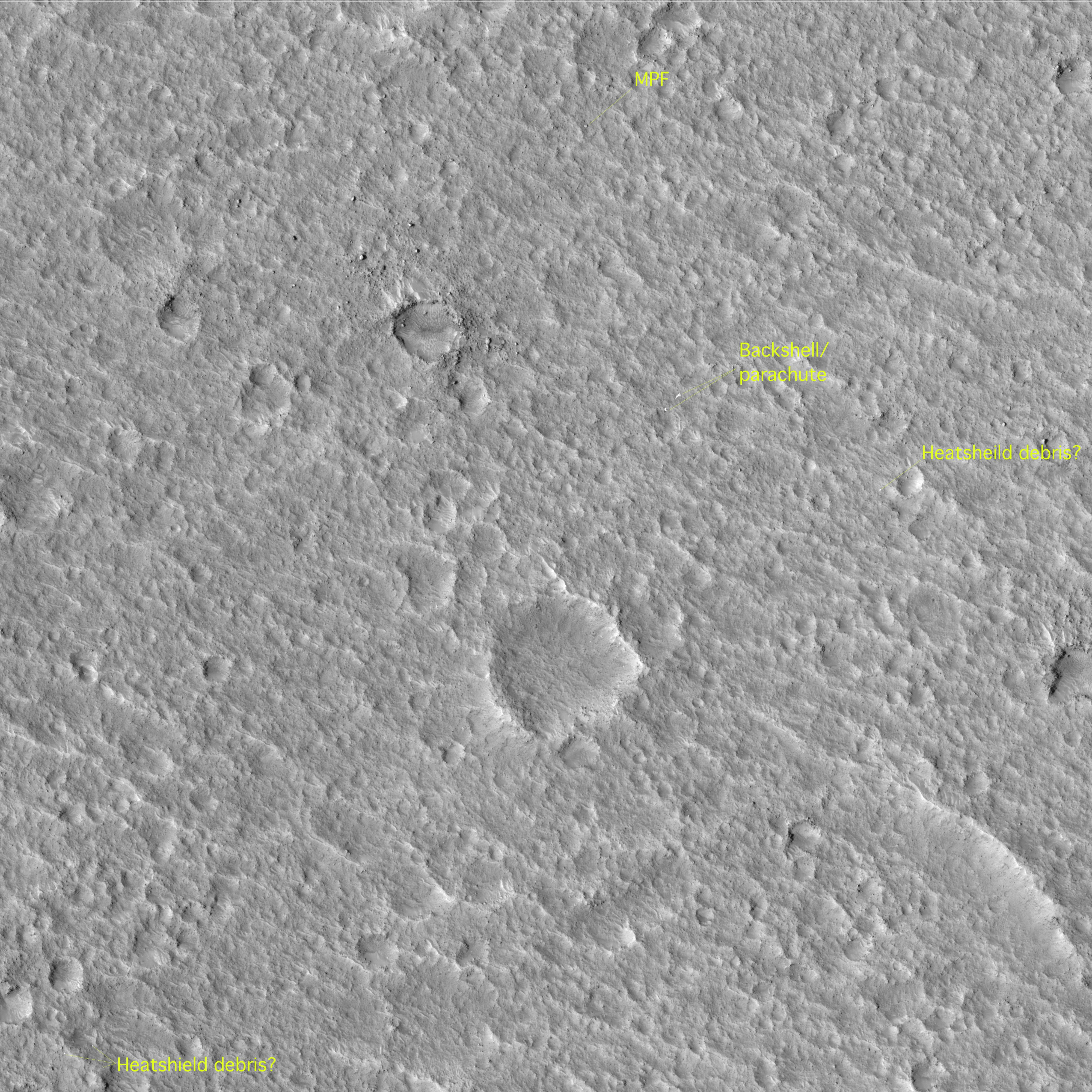
One of the solid rockets that are firing:
commons.wikimedia.org/wiki/File:Mars_Pathfinder_spacecraf...
Credit: Wikimedia Commons
8.5” x 11”. Note...Appreciate...the attention to detail. What a gorgeous work. Pat Rawlings.
Lunar Module 12 (LM-12)/Challenger ascent stage cabin 'baseline' documentation photo. Taken at the Manned Spacecraft Operations Building (MSOB), 13 March 1972.
In this view, looking up at the ceiling above LMP Harrison Schmitt’s station, the upper right corner of panel no. 2, to include some of its displays & controls, is at the far left. To its right is the Alignment Optical Telescope (AOT) guard, it's optics & controls wrapped in plastic for protection. Two sets/groupings of main panel/cabin floodlights are ‘above’ & ‘below’ to its immediate right. Farther to the right is the centrally located/consolidated controls for those lights, in addition to two utility light receptacles. At the lower left-hand corner, the angled/canted (from this perspective) top edge of the LMP window can be seen, with a protective panel over it, which apparently has a circular ‘window’. Running along the top edge of the window are two coiled cables, at least one of which connects to the 16mm DAC, when it’s affixed. The triangularly peaked recessed area accommodates the camera, which is mounted to the lighter gray bar bearing the long red-ink serial/part no. Finally, along the bottom of the photograph is the top edge of circuit breaker panel no. 16.
As if all of that wasn’t enough, the glass-reinforced perforated covers were not originally planned for the LM interior. The ceiling originally had exposed cabling, which Astronauts raised concerns about possibly damaging. As a result, one of the eight ‘crew compartment design’ Requests For Change (RFC) that were approved - which required hardware changes - was the addition of the ceiling covers to protect the wiring and prevent the collection of debris in this area.
END TRANSMISSION
“Jupiter's satellite Io poses before the giant planet in this photo returned January 17, 1979, from a distance of 29 million miles (47 million kilometers). The satellite's shadow can be seen falling on the face of Jupiter at left. Io is traveling from left to right in its one-and-three-quarter-day orbit around Jupiter. Even from this great distance the image of Io shows dark poles and a bright equatorial region. Voyager will make its closest approach to Jupiter -- 174,000 miles (280,000 kilometer) -- on March 5. It will then continue to Saturn in November 1980, Meanwhile Voyager 2, a sister spacecraft, will fly past Jupiter July 9, 1979, and reach Saturn in August 1981. This color image was taken through orange, green and blue filters. The Voyagers are managed for NASA's Office of Space Science by Jet Propulsion Laboratory.”
Above at:
photojournal.jpl.nasa.gov/catalog/PIA00455
Credit: JPL Photojournal website
If the above isn't enough:
fineartamerica.com/featured/2-voyager-1-photo-of-jupiter-...
Credit: FINE ART AMERICA website
Obviously, they both use the same third party vendor:
sciencephotogallery.com/featured/2-voyager-1-photo-of-jup...
Credit: Science Photo Gallery website
“An Apollo/Saturn V space vehicle carrying Apollo 10 astronauts Thomas P. Stafford, John W. Young and Eugene A. Cernan lifted off at 12:49p.m., DST, May 18, 1969, from the Kennedy Space Center’s Launch Complex 39B. The 363-foot-high vehicle launched the astronauts on the first leg of their 73-hour, 240,000-mile-journey to the moon. Apollo 10 is a dress rehearsal for the first manned lunar landing and includes all major aspects except the actual lunar touchdown. During Apollo 10, Stafford and Cernan will descend in a lunar module spacecraft to within eight nautical miles of the Moon’s surface while Young pilots the command module at an altitude of 60 nautical miles. Following an eight-and-a-half exercise, Stafford and Cernan will rendezvous and dock their lunar module with the command module and return to the mother ship for the remainder of their 60 hours or 30 revolutions in lunar orbit. The astronauts will conduct lunar navigation tasks and will photograph Apollo landing sites in order to provide information for the succeeding landing mission. Several color television transmissions are planned during the National Aeronautics and Space Administration’s eight-day mission. (The Saturn V generates a liftoff thrust of 7.7 million pounds).”
“Jupiter's faint ring system is shown in this color composite as two light orange lines protruding from the left toward Jupiter's limb. This picture was taken in Jupiter's shadow through orange and violet filters. The colorful images of Jupiter's bright limb are evidence of the spacecraft motion during these long exposures. The Voyager 2 spacecraft was at a range of 1,450,000 kilometers (900,000 miles) about two degrees below the plane of the ring. The lower ring image was cut short by Jupiter's shadow on the ring.”
www.jpl.nasa.gov/images/pia01529-jupiter-ring-system/
pds-rings.seti.org/press_releases/pages/PIA01xxx/PIA01529...
“This view, looking northward toward the equator, is the closest picture of Jupiter’s Great Red Spot taken by Pioneer 11. (Distance is 545,000 km or 338,000 mi).
More details of the Great Red Spot (which is large enough to swallow three Earths) and its surrounding region are visible here than have ever been seen before. The picture was taken in red and blue light and color.
Details of the flow, already known to exist, of the white cloud streams north of the Spot [flow] from right to left in the picture, and flow from left to right in the strip of clouds south of the Spot is clearly visible. The triangular regions on either side of the Spot appear to be areas where these two streams converge to flow side-by-side in opposite directions.
Details visible within the Spot (especially in the blue light picture) seem to show counterclockwise spiral there. Theory suggests that the Spot rotates counterclockwise due to the flow in the opposite directions of cloud streams north and south of it.
There also appears to be a narrow jet stream of brown material flowing southwestward above and to the left of the Spot. Strung out along the boundary between the white South Tropical zone, containing the Spot, and the brown belt north of it, is a series of small, white cloud puffs. (Puffs are only relatively small, typically about the size of Ohio). The puffs may be an example of flow instability between the zone and belt, where cloud currents are fastest relative to the planet.
The white oval below the right end of the Great Red Spot is one of three white ovals which are usually 120° apart around Jupiter, and have been known for 30 years. The oval’s position relative to the Red Spot changes with time due to a different rate of flow of the cloud current which contains it. New details of the white oval in this picture, such as the circular “eye” in its center, strongly suggest rotational motion.
Between the Red Spot and the white oval is a stream of brownish cloud material. Turbulance extending out to the right of the Spot seems to show (especially in the red light view) a large wake created by this atmosphere stream. This cloud stream appears to be one of the first examples seen of transfer of mass between the belts and zones, something predicted by theories on Jovian meteorology.
Pioneer 11, which took the picture, flew past Jupiter last December. The Pioneer Project is managed by NASA’s Ames Research Center, Mountain View, Ca. The spacecraft were built by TRW Systems.
Scientists believe that understanding of Jupiter’s Meteorology, and of other planets, will be of major importance in the understanding of weather on Earth.”
Also, the image (in color) and associated caption, on page 20:
“One of the best Pioneer images of Jupiter was obtained at a range of 545000 kilometers by Pioneer 11. Structure withing the Great Red Spot and the surrounding belts and zones can be seen. There was less turbulent cloud activity around the Spot at the times of the Pioneer flybys then was seen five years later by the Voyager cameras.”
At:
ntrs.nasa.gov/citations/19820018276
Finally:
From “NASA SP-446/PIONEER: FIRST TO JUPITER, SATURN, AND BEYOND”, pages 169 & 170 where the orthographic(?) projection of the image is shown as; (a) color composite, (b) blue channel image, and (c) red channel image, with the following accompanying text:
“For planetary astronomers, this image of the Great Red Spot of Jupiter was one of Pioneer 11’s most exciting results. From Pioneer 10, the highest-resolution image of the spot had been degraded by radiation problems, but Pioneer 11 obtained this unique image (Figure 9-11a). The area covered by the image on the planet is shown in the line drawing insert (d) on this page.
The image, obtained 545,000 km (339,000 miles) above the cloud tops, contains more than 4,000 individual pixels (see chapter 7) of measurable data in the red area of the spot a wealth of detailed markings since each pixel represents an area of approximately 237 km (147 miles) square. Scientists will be able to compare this image with those obtained by other spacecraft in later years to ascertain how the structure of the Spot changes with time.
Planetary scientists have derived new interpretations of the Great Red Spot from this image. Despite the relatively high resolution obtained, there is much less fine structure visible in the spot than in comparable areas at other latitudes (e.g., in Figure 9-12 and 914). The Great Red Spot appears to lie in the most quiescent zone of Jupiter, which may contribute to its stability.
The blue image has little internal detail (Figure 9-11b), the main feature being the dark border on the periphery of the spot. A break appears in the border in the northeast portion of the spot, where some of the red material appears to intermix with the South Tropical Zone.
The red image reveals much internal detail (Figure 9-11c), perhaps the most significant being two circular outlines that cross over near the center of the spot. This same feature also appeared in the Pioneer 10 images. This image does not show clear evidence of motions within the spot. The image does not show direct evidence of flow lines from any single region inside the spot, which could he interpreted as a source or a sink of red material.”
From/at:
atmos.nmsu.edu/data_and_services/atmospheres_data/SATURN/...
A beautiful depiction of the Hubble Space Telescope (HST) basking in the sun by the incredibly talented Paul Hudson. Orientation of the photo, although arbitrary, was chosen because the sun by convention should be ‘up’ & it’s the closest to Mr. Hudson’s other, iconic depiction of the engineering marvel, aka HST.
The photograph was featured as the centerfold of a STS-31 presentation.
“Color-enhanced image of sunset on Mars, recorded by the Viking 1 lander. Part of the spacecraft is just visible at bottom right, colored dark blue. The contouring effect around the setting sun is a result of the imaging system.”
Disappointingly, the image and the above, which may have been part of the original NASA caption, seem to only be available at the ‘pay to play’ sites.
A high contrast version is contained within:
history.nasa.gov/EP-177/ch8-2.html
Although I can see how this has an artistic, mod/pop…whatever it’s called, appeal, I’ve always disliked it. Yet it seemed to have been oft-reproduced. I remember seeing it as a poster, lithograph of course…I think even in NASA/JPL informational/promotional material.
It definitely looks way better as an actual photograph print, not the garish, ‘HDR’, end of “2001: A Space Odyssey”, comic book-like look I seem to recall & refer to above.
i.discogs.com/kAPI00d2TdTseTZwVL5YXOR03oD9osbsjRzeG_z1zbk...
i.discogs.com/Lc1xLVGuQIhLAr66dCTnXmd-qAXxrQPVuiUYqO3HBOU...
Credit: Both above credit Discogs website
Further, although the image is subdued & accurate, the ‘contour lines’ do seem to match. Maybe just processed differently? IDK:
“Viking 1 Lander image of a Martian sunset over Chryse Planitia. In this image the sun is 2 degrees below the local horizon. The banding in the sky is an artifact produced by the incremental brightness levels of the camera. This image was taken on the 30th Martian day (sol) after touchdown, at 19:13 local time. The camera is pointing towards the southwest.”
At:
nssdc.gsfc.nasa.gov/imgcat/html/object_page/vl1_12a240.html
Credit: NSSDCA website
Also:
commons.wikimedia.org/wiki/File:Viking_sunset.jpg
Credit: Wikimedia Commons
Finally, featured on the cover. The right half of it that is:
Comparative color-enhanced/false-color Voyager 1 & 2 images (left & right, respectively) of Saturn, taken October 1980 and ~July 1981, during the flybys of the ringed planet by these two remarkable spacecraft.
Left:
nssdc.gsfc.nasa.gov/imgcat/html/object_page/vg1_p22994c.html
Credit: NASA Space Science Data Coordinated Archive website
Right:
photojournal.jpl.nasa.gov/catalog/PIA03152
Credit: JPL Photojournal website
nssdc.gsfc.nasa.gov/imgcat/html/object_page/vg2_p23880c.html
Credit: NASA Space Science Data Coordinated Archive website
photojournal.jpl.nasa.gov/catalog/PIA03152
Credit: JPL Photojournal website
This captivating photograph captures the historic B&O Railroad Bridge crossing the Shenandoah River at Harpers Ferry, West Virginia. This site marks the confluence of the Shenandoah and Potomac rivers, nestled beneath the imposing rock face of Maryland Heights—a rugged landmark that looms above the scene. The bridge, a testament to 19th-century engineering and design, was a vital transportation route during the Civil War and remains a crucial part of American railroad history.
The steel truss bridge stretches across the river on sturdy stone piers, its weathered ironwork echoing the industrial past that shaped Harpers Ferry’s identity. Trains, still in service today, traverse the bridge, connecting the past with the present as they journey through the Appalachian landscape. The piers of an older bridge can be seen in the foreground—remnants of an earlier crossing that was destroyed during the war, a silent witness to the town’s tumultuous history.
Beyond the bridge, the stone ruins of earlier bridge abutments stand on the riverbank like sentinels, each block telling a story of conflict and resilience. Harpers Ferry was a strategic target during the Civil War, repeatedly contested by Union and Confederate forces. These bridge piers once supported a crucial link in the transportation network that supplied troops and carried commerce along the B&O Railroad.
The photograph’s composition draws the eye along the bridge to the dark, cavernous train tunnel cut into the mountain—a passage through which countless trains have roared since the 19th century. Above, the clouds dance in a dynamic sky, a perfect counterpoint to the river’s steady flow and the rugged cliffs beyond.
This image captures the enduring intersection of nature, history, and technology in Harpers Ferry, a town that continues to honor its place in America’s story.
The south tower of Joseph Strauss and Irving Morrow's 1937 span, caught in the narrow window when twilight is still bleeding color into the sky and the marine layer is just beginning to commit. Fog hangs behind the tower in a pale wash, softening the upper structure into the Marin Headlands. The aircraft beacon still fires red at the apex. Morrow's International Orange — chosen specifically to harmonize with the rust tones of the headlands rather than the battleship grey the Navy wanted — reads almost luminous against the cooling blue atmosphere.
This vantage from the south anchorage bluffs trades the postcard sweep for something more grounded. That concrete stairway threading down at lower left is utilitarian Park Service infrastructure, and it gives the frame a human-scale entry that the wider compositions lack. Native coastal scrub layers across the foreground — part of the Presidio's ongoing restoration of the bluff ecosystem — leading the eye up through the Welcome Center pavilions toward the deck, where the roadway lights pull a luminous arc across the span as it bends toward Fort Point.
Twilight here is brief. Earlier the sky reads colder; later the tower goes flat against black. This is the seam.
“APOLLO 11 LIFTOFF----------The huge, 363-foot tall Apollo 11 (Spacecraft 107/Lunar Module 5/Saturn 506) space vehicle is launched from Pad A, Launch Complex 39, Kennedy Space Center, at 9:32 a.m. (EDT), July 16, 1969. Aboard the Apollo 11 spacecraft were Astronauts Neil A. Armstrong, commander; Michael Collins, command module pilot; and Edwin E. Aldrin Jr., lunar module pilot. Apollo 11 is the United States’ first lunar landing mission.”
Wow:
www.sothebys.com/en/buy/auction/2019/space-photography-on...
Credit: Sotheby's website
Also wow:
www.auctionzip.com/auction-lot/apollo-11-launch-nasa-numb...
Credit: AuctionZip website
$2,300 (plus 25% Buyer's Premium):
historical.ha.com/itm/explorers/space-exploration/apollo-...
Credit: Heritage Auctions website
Speaking of high costs, along with insightful, albeit depressing discussion of current ‘back to the moon’ reality:
spacenews.com/cost-and-schedule-overruns-continue-to-grow...
Credit: SPACENEWS website
Have you ever been to historic places in south India and ever wondered why the heck on earth you find so many ugly holes on huge rocks, right next to nice carvings and scriptures? Well if you have the discovery DVD's and seen it already, good enough. The folks who still have no clue, listen carefully.
The maximum load that you are allowed to transport in the USA by road is about 30 tonnes. Anything more than this requires a license and specialized equipment and of course a lot of things. Now come to India, rewind your time way back to say 3500 B.C or 300 B.C or 700 A.D when most of these huge temples were built. We did not have airplanes, we did not have trucks or cranes to do the job. Nope, god did not do shit as usual, nor did black magic or divine power. Engineering science did the job.
The average weight of each and every rock is about 1300 tonnes and many of them shot past the regular 7000 tonne mark. Now how do you take these rocks up the hill, about 700 meters up the sea level? The simple answer is you gotta break them into pieces and take them, but then how the heck do you break such huge rocks. If your answer was drill and hammer them out, sorry mate, you scored an F :-) (i did too!)
Drilling, hammering et all was time consuming and resourceful and required impossible amount of manpower and horsepower. Explosives are a thing that happened a few hundred years ago and were unheard of during these times. Even if they were available, blasting off mountain rocks meant you could not use them properly and cut it on a shape you wanted them to come out for specific purposes. So, here is what they did.
Instead of breaking the entire rock, they drilled very small holes into them along the line where the rock was meant to be broken. As soon as the holes were drilled, soft pieces of wood was thrust into these holes and the rock was heated so that it would expand (remember the physics lesson, objects expand on heat) and they thrust more soft wood into these holes and sealed them with mud and plastered it with lime. Now pour cold water over it in large quantities, the rock cools down and contracts, however the wood inside absorbs the water and expands due to its soft nature and absorbing characteristic. So rock shrinks, wood enlarges/expands and thereby forces the rock to crack along the lines where the wholes were drilled.
Ta daa! You have a neatly cut rock precise to the line where the engineer drew the line and you could not cut them again into smaller pieces till they could be carried over or carved here for whatever use they were meant to be. That's exactly how they did it. Engineering freaking genius, 1000's of years back!
Canon EOS 400D with the Sigma EF 24 - 70 MM F/2.8, Aperture Priority, F/8 at 1/200th of a Second, ISO100.
A stunning view of the Saturn 500F/Facilities Verification/Integration Vehicle, possibly during rollout and the climb up the incline to Launch Complex 39A, 25 May 1966.
“Two brown ovals, at right, some 10,000 kilometers (6,000 miles) across, were found at approximately 40° and 60° latitude in Saturn's northern hemisphere by Voyager 1. The photo was taken on November 7, 1980, from a range of 7,500,000 kilometers (4,600,000 miles). The polar oval (upper right) has a structure similar to the Saturn red spot located in the southern polar latitudes. The Voyager Project is managed by the Jet Propulsion Laboratory for NASA.”
nssdc.gsfc.nasa.gov/imgcat/html/object_page/vg1_p23073.html
Credit: NSSDCA website
photojournal.jpl.nasa.gov/catalog/PIA00026
Credit: JPL Photojournal website
“Astronaut Jeffrey A. Hoffman, anchored on the end of the Remote Manipulator System (RMS) arm, is pictured with the Wide Field/Planetary Camera (WF/PC I) during the third of five extravehicular activity’s (EVA). Astronauts Hoffman and F. Story Musgrave, seen near the stowage area for the WF/PC, had earlier installed the new camera (note white rectangle) on lower portion of telescope.”
Note the newly installed, but not yet deployed solar arrays on the Hubble Space Telescope (HST). Per the caption of another photograph from the mission, one of the original solar arrays can be seen in the Solar Array Carrier (SAC), near the lower left corner of the photograph.
“This wide shot of the Hubble Space Telescope (HST) in Discovery’s cargo bay, backdropped against Australia, was taken during the fifth space walk added to complete servicing of the orbiting observatory. Astronauts Steven L. Smith (center frame) and Mark C. Lee (on robot arm) are conducting a survey of the hand rails on HST. In foreground is the hatchway that connects to Discovery’s shirt sleeve environment of the crew cabin”
Osaka City’s iconic Ferris wheel stands as a marvel of modern engineering and a beacon of urban excitement. This towering structure punctuates the city skyline with its vibrant yellow and green gondolas, offering breathtaking views of Osaka Bay and the sprawling urban landscape. Originally constructed as part of the city’s push to invigorate tourism, the Ferris wheel serves as a symbol of Osaka's balance between tradition and innovation.
The Ferris wheel's metallic frame reflects sunlight during the day and transforms into a dazzling spectacle of lights at night, drawing visitors from across the globe. Each gondola is meticulously designed for comfort, featuring panoramic windows that allow riders to immerse themselves in the views, whether it’s the shimmering waters below or the bustling city streets. The wheel’s impressive height, combined with cutting-edge technology, ensures a smooth and stable ride, even on windy days.
For architecture enthusiasts, the structure exemplifies contemporary design with its geometric precision and use of durable materials. Its seamless integration into the cityscape highlights Osaka’s forward-thinking urban planning. The Ferris wheel is strategically located near other major attractions, making it an ideal starting or finishing point for a day of exploration.
Insiders recommend visiting at sunset for the most spectacular experience—when the city is bathed in golden light, and the skyline begins to sparkle. Whether you're a thrill-seeker or a photography enthusiast, this Ferris wheel offers an unforgettable perspective on the vibrant energy of Osaka.