View allAll Photos Tagged engineeringmarvel
“South tracking camera shows the moment the Apollo 8 S-IC stage begins its separation from the S-II stage, December 21, 1968.”
Talk about a rarely seen - let alone correctly (I’m pretty sure) identify/attribute - photograph/image. The above is paraphrased from the “APOLLO 11 SPACE” website, at:
apollo11space.com/how-did-the-saturn-v-stages-separate/
Specifically:
i0.wp.com/apollo11space.com/wp-content/uploads/2021/11/So...
Although I’d never heard of them before - and not to be an ass - but I lend much more credence to their identification than to anything N(Ass)A produced. And it looks like they have plenty of other interesting stuff.
With much appreciation to them!
“STS-41B EVA VIEW --- Astronaut Bruce McCandless II, one of two mission specialists participating in a historical Extravehicular Activity (EVA), is a few meters away from the cabin of the Earth-orbiting Space Shuttle Challenger in this 70mm frame. This Extravehicular Activity (EVA) represented the first use of a nitrogen-propelled, hand-controlled device called the Manned Maneuvering Unit (MMU), which allows for much greater mobility than that afforded previous spacewalkers who had to use restrictive tethers. Robert L. Stewart later tried out the MMU McCandless is using here, and the two of them tested another similar unit two days later. Inside the spacecraft were astronauts Vance D. Brand, commander; Robert L. Gibson, pilot; and Ronald E. McNair, mission specialist.”
7.875” x 9.611”. The photograph literally has a mirror-like gloss and is absolutely stunning. I’ve only seen a few official (I think) NASA photographs on “FUJIFILM: Fujicolor Crystal Archive Paper”. I think it was used toward the end of NASA’s printing of ‘photo paper’ photographs, ca. 1998 and later. If so, this may be a second-generation reissue.
Lockheed artist Gordon Raney’s 1985 depiction of the Hubble Space Telescope (HST), berthed to the Flight Support System (FSS) within the orbiter vehicle’s payload bay, during a ‘maintenance & refurbishment’ mission.
My original thought regarding what's transpiring here was 'artistic license'; however, vague recollection & additional research reveals that HST was reboosted during servicing missions 1, 2 & 3B...which would then also explain the undeployed configuration of the solar arrays. Additionally, I suppose the angled positioning of HST would also reduce the torque/stress on its structure during the reboost.
esahubble.org/about/history/sm3b_a_little_boost/#:~:text=....
Credit: ESA/Hubble website
And since one or two of you were (or eventually will be) thinking “I wonder how’d that whole HST/orbiter berthing thing/system work?” Although some of it’s Servicing Mission 4 (SM-4) specific, it’s still applicable to any/all of the servicing missions:
“Flight Support System
The FSS is a maintenance platform used to berth the HST in the payload bay after the Atlantis crew has rendezvoused with and captured the telescope (see Fig. 2-4). The platform was adapted from the FSS first used during the Solar Maximum repair mission and was converted to use with HST. It has a U-shaped cradle that spans the rear of the bay. A circular berthing ring with three latches secures the telescope to the cradle. The berthing ring can rotate Hubble almost 360 degrees (176 degrees clockwise or counterclockwise from its null position) to give EVA astronauts access to every side of the telescope.
The FSS also has the capability to pivot the telescope, if required for servicing or reboosting. The FSS’s umbilical cable provides power from Atlantis to maintain thermal control of the telescope during the servicing mission.
On SM4 the FSS also carries a Soft Capture Mechanism (SCM) on its berthing and positioning system platform. When attached to the HST aft bulkhead, the SCM will enable and assist in the safe de-orbit of the telescope at the end of its useful life by providing a docking interface that is intended to be compatible with future launch vehicles.”
At/from:
www.nasa.gov/pdf/327688main_09_SM4_Media_Guide_rev1.pdf
Unfortunately, nothing on Mr. Raney.
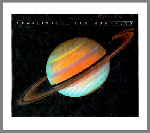
“This image of Saturn, taken by the Voyager 1 spacecraft on Oct. 18, 1980, was color-enhanced to increase the visibility of large, bright features in Saturn's North Temperate Belt. It is believed that these spots might closely resemble gigantic convective storms (similar to, but much larger than thunderstorms in Earth's atmosphere) with upwelling from deep within Saturn's atmosphere. The nature of the dark spots like the one visible on the northern edge of the belt is not yet clearly understood, though they seem to resemble equally mysterious features seen on Jupiter. The largest violet-colored cloud belt (its true color is brownish) is Saturn's North Equatorial Belt. The distinct color difference between this and other belts and zones may be due to a thicker haze layer covering the northern portion of the belt. The Southern Hemisphere of the planet (below the rings) appears bluer than the Northern Hemisphere because of the increased scattering of sunlight upon that area due to the spacecraft's point-of-view. Numerous gaps and divisions in the rings are becoming more apparent as Voyager 1 approaches Saturn. The newly discovered dark radial features in the rings are faintly shown on the lower right portion of the rings. Three separate Voyager images taken through ultraviolet, green and violet filters were used to construct this blue, green and red color composite of Saturn. The lower edge of the rings were "clipped" due to a slight drift of the spacecraft. Color spots in the rings are an artifact of image processing. The Voyager Project is managed for NASA by the Jet Propulsion Laboratory, Pasadena, California.”
Effects of improper/careless handling & possible emulsion artifacts do not detract from the image.
Unlike most reproductions of this image, to include my previous post (of another issuance), this is oriented to correspond with the official description on the verso.
nssdc.gsfc.nasa.gov/image/planetary/saturn/saturn_false.jpg
nssdc.gsfc.nasa.gov/photo_gallery/caption/saturn_false.txt
nssdc.gsfc.nasa.gov/imgcat/html/object_page/vg1_p22994c.html
All above credit: Both above credit: NASA Space Science Data Coordinated Archive (NSSDCA) website
Due to its colorful nature, and of course, rings, I believe this was one of the more reproduced, popular and maybe even somewhat iconic Voyager images of Saturn. To include gracing the cover of the following book:
images-na.ssl-images-amazon.com/images/I/51i1OgwMneL.jpg
Credit: Amazon.com website
Neither here nor there, but I highly recommend this book. One of the better “space” pictorial books of the time, with some really nice & varied photographs, reproduced really well on nice thick paper.
As dusk settles over Michigan, the Mackinac Bridge emerges as a monumental silhouette against the twilight. This photograph captures the stunning spectacle of the bridge at night, illuminated by a constellation of lights that trace its grand span across the Straits of Mackinac.
“Apollo 15 modified lunar module for the ninth manned Apollo crew. The members of the Apollo 15 prime crew are James B. Irwin, lunar module pilot; David R. Scott, commander; and Alfred M. Worden, Jr., command module pilot. Apollo 15 is the fourth lunar landing mission and the first to use the Lunar Roving Vehicle to traverse the lunar surface.”
The plume deflector under the near RCS quad is…not there, but the other two are. Other than that it’s great, to include the lunar surface sensing probes, correctly located/depicted.
Looks to be from the same base diagram, with ample, informative & useful callouts. Well done:
airandspace.si.edu/multimedia-gallery/5212hjpg
Credit: Smithsonian NASM
“Apollo 8 launched on December 21, 1968 and sent the first humans out of Earth's orbit. It carried Frank Borman, Jim Lovell and William Anders on the first launch of a Saturn V with a crew onboard on a mission to orbit the Moon 10 times before returning to Earth on December 27.”
The above is associated with NASA photo S-69-15558, a near equivalent image.
~7.675 x 10”, likely trimmed. Despite some varied minor flaws resulting from improper handling & minimal care, the photograph has retained nice gloss & detail.
The two diagonal lines to the left of the Saturn V are not photo emulsion artifacts, flaws or scratches, since they show up in other photographs of this and other Saturn V launches. I suppose they’re guy wires of some sort, supported by the one near the lower left being dark, in effect ‘silhouetted’ against the brighter billowing exhaust gases behind it, while the lighter one – which looks like it leads up to the crew access arm level – is due to it being illuminated by the F-1 engine plumes below.
WC 6588 flies solo on a train of coke empties over the St. Croix River on September 21, 1997.
RP reject, too much grain
“Three different rocket engines used to power the two Saturn vehicles are lined up at the National Aeronautics and Space Administration’s Michoud Assembly Facility. The Uprated Saturn I and Saturn V vehicles, the first stages of which are assembled at Michoud, are designed for use in Project Apollo, the United States’ manned lunar exploration program. The engines were built for NASA by the Rocketdyne Division of North American Aviation, Inc. Eight of the H-1 engines, (left) will develop 1.6 million pounds of thrust at liftoff for the Uprated Saturn I first stage. Five F-1 engines (center) will provide 7.5 million pounds of thrust for the Saturn V first stage. The J-2 engine (right) is used on both vehicles. Five J-2’s will give one million pounds of thrust to the second stage of the Saturn V and one J-2 will power both the third stage of the Saturn V and second stage of the Uprated Saturn I. The Uprated Saturn I will be used for astronaut training and testing the Apollo spacecraft’s systems, while the Saturn V will launch manned Apollo flights to the moon within this decade.”
Quite the lineup, eh?
FIFTY-FIVE (55)+ years ago!
Note that the F-1 does not have its nozzle extension attached.
Well-written, commensurate with the amazing quality, depth, richness & detail of the photograph.
Finally, too cool:
rocketreference.com/wp-content/uploads/2019/02/H-1-F-1-Co...
Credit: "ROCKETreference.com" website
“ARTIST: RICK GUIDICE PIONEER F SPACECRAFT IN ORBIT AROUND JUPITER”
NO……….AND……….NO ! ! ! ! !
I’m sorry, I can’t help it and I KNOW I shouldn’t be burning calories, popping blood vessels, raising my blood pressure, seeing red, etc., etc., but, damn, Damn, I Mean DAMN!!! REALLY???
I can ALMOST…NOT QUITE, but almost overlook the Guidice citation. He was producing a lot, if not most, of the conceptual Pioneer 10/11 Jupiter/Saturn & beyond artwork for the ARC during the early(?) – mid 70’s. However, wouldn’t the photograph/imagery, printing/publication department, section, office, supply/remedial writing room...clown factory…whatever it was called…dolt’s/dolts’ source work of this also have contained the artist’s signature, BEFORE THEY(?) would’ve cropped or otherwise removed it???
So, what, was Guidice was just an ‘educated’ guess? AGAIN, the bar was/is(?) EXCEEDINGLY LOW, so they get a pass on this.
And, it’s “Pioneer F” pre-launch/mission/flight, “Pioneer 10” upon launch/liftoff. A begrudging pass.
BUT - NOT - ON - THIS:
“…IN ORBIT AROUND JUPITER…”
Being a fairly historic ‘first’ & significant scientific/technical achievement, as far as space stuff goes, the media gave it plenty of coverage - providing desperately needed positive exposure. I remember such because I was really into it by that time. And as Pioneer neared Jupiter, IT WAS PUT OUT, OVER & OVER & OVER AGAIN that the spacecraft would ZOOM BY the planet, REALLY REALLY FAST, destined to eventually become the FIRST human-made object to LEAVE the solar system!!! You’d have to be living under - no, INSIDE a rock, beneath a glacier, in Antarctica, with earplugs & blinders on, to NOT know this…OR I suppose, work at NASA in whatever “office” responsible for releasing beautiful artwork of the aforementioned impending spectacular achievement.
To exacerbate this crap, as with way too many other instances of NASA photo-associated buffoonery, in lemming-like fashion, it’s propagated across the internet.
At least they stumbled upon the image & inadvertently posted it:
images.nasa.gov/details-ARC-1972-AC72-1281
See also:
solarsystem.nasa.gov/resources/708/pioneer-10-at-jupiter-...
On the bright side, it’s by talented NASA(?)/NASA-commissioned(?) artist Joseph “Chris” Chizanskos. A HUGE WIN+!!! Unfortunately though, having been inside the event horizon of NASA’s artist identification, acknowledgment, recognition & preservation blackhole, there’s nary a trace of him, other than the cursory info by way of the NASA Art Program thing from back then. Also, regrettably, there appears to be only a blip of a gentleman with that name having passed in 1973.
An absolutely beautiful image. I’m assuming the ominous dark area just above & behind the spacecraft is the Great Red Spot. Probably no greater resolution of it available at the time? I also like the visually evident actual physical texture of the image, I suppose picked up by whatever photo, scanning, illumination equipment used to capture the image. Bravo at least on that! So, reasonable to conclude it was outsourced then.
Although obscure as hell, at least there’s this:
collections.si.edu/search/results.htm?q=%22Joseph+Christo...
Credit: Smithsonian NASM website
“This photograph of Neptune was reconstructed from two images taken by Voyager 2's narrow-angle camera, through the green and clear filters. The image shows three of the features that Voyager 2 has been photographing during recent weeks. At the north (top) is the Great Dark Spot, accompanied by bright, white clouds that undergo rapid changes in appearance. To the south of the Great Dark Spot is the bright feature that Voyager scientists have nicknamed "Scooter." Still farther south is the feature called "Dark Spot 2," which has a bright core. Each feature moves eastward at a different velocity, so it is only occasionally that they appear close to each other, such as at the time this picture was taken. The Voyager Mission is conducted by JPL for NASA's Office of Space Science and Applications.”
photojournal.jpl.nasa.gov/catalog/pia01142
Credit: JPL Photojournal website
“SATURN APOLLO 501 IN HIGH BAY 1, WITH WORK PLATFORMS RETRACTED. VAB HIGH BAY 1.
5-24-67”
Note access arm No. 8 “Service Module (inflight)” directly behind the CSM. Access arm No. 9 “Command Module (preflight)” is to the far right. Speaking of the CSM, note also the lack of RCS thrusters on the SM. Kind of clue as to vehicle identification.
And, unless something else surfaces, maybe on the verso of a “S-67-XXXXX” version of this photo - if such exists - the following lame, I’m sure contemporary pablum is apparently what’s meant to pass as the official description/caption:
“This photograph depicts the Saturn V vehicle (SA-501) for the Apollo 4 mission in the Vehicle Assembly Building (VAB) at the Kennedy Space Center (KSC). After the completion of the assembly operation, the work platform was retracted and the vehicle was readied to rollout from the VAB to the launch pad. The Apollo 4 mission was the first launch of the Saturn V launch vehicle. Objectives of the unmanned Apollo 4 test flight were to obtain flight information on launch vehicle and spacecraft structural integrity and compatibility, flight loads, stage separation, and subsystems operation including testing of restart of the S-IVB stage, and to evaluate the Apollo command module heat shield. The Apollo 4 was launched on November 9, 1967 from KSC.”
Surprisingly, the above, with a bullshit, probably arbitrarily assigned “NASA ID” of 6754387 is actually available at:
images.nasa.gov/details-6754387
Unfortunately, as with many others, the description has been propagated everywhere. While I’ve read MUCH worse, it’s merely a copy/paste from some Apollo 4 document, which doesn’t address the context of the photograph…that is, what’s actually going on…the REASON the photograph was taken.
With that, the recognition/correct identification of the content of this photograph, along with the date, hence its pertinence to the problematic history of the SA-501 vehicle, has been…take your pick: lost, overlooked, unrecognized, omitted…something unacceptable.
For starters, the NASA photo ninjas, especially at the time of the photo’s processing, i.e., 1967, should’ve recognized that the CSM atop the vehicle was NOT the flight CSM (CSM-017). It ALSO should’ve been easily/readily identified as M-11, the Flight Verification Vehicle (FVV), it having been photographed a bazillion times during 1966 as part of SA-500F photo documentation.
As if that weren’t enough, within the multiple regurgitations of the trials & tribulations of making Apollo 4 happen, there’s not a mention of M-11, other than within the following, which although incomplete, with its own errors, at least references it…ONCE:
“The third stage (S-IVB) was the first major component of Apollo 4 to be delivered at KSC. It arrived from Sacramento aboard the Guppy aircraft on 14 August 1966 and went immediately into a low bay of the assembly building for inspection and checkout. The following week the spacer and instrument unit arrived. On 12 September, as Peter Conrad and Richard Gordon prepared to blast off in Gemini 11, the barge Poseidon sailed into the Banana River with the first stage. Boeing gave it a lengthy checkout in the transfer aisle of the high bay before erecting the booster on 27 October. During the following week, technicians stacked the remaining launch vehicle stages, using the spool for the absent S-II. There were a few problems - the checkout of the swing arms took an extra two days and a cooling unit for the instrument unit sprang a leak - but the launch team, still counting on the mid-November delivery date for the S-II, hoped to roll the complete vehicle out to pad A by 13 January 1967.
By late November the Apollo Program Office had moved the S-II's arrival back to January, and the launch back to April. Since spacecraft 017 would not arrive for another three weeks, KSC erected the facilities verification model of Apollo on 28 November.
[The first linked black & white photograph by Cliff Steenhoff below, depicts such.]
This allowed North American to check out some of its spacecraft support equipment. The first week in December the memory core in a digital events evaluator failed after intermittent troubles; cracked solder joints were blamed. A hurried repair put the computer back on line.
The command-service module arrived at KSC on Christmas Eve and was mated to the launch vehicle on 12 January 1967. That tardy prima donna, the S-II stage, finally appeared on 21 January. Tank inspection, insulation, and engine work were in progress by the 23rd. Test crews found damaged connectors on three recirculation pumps and set about investigating the extent of the rework that would be necessary. While inspecting the liquid hydrogen tank on the second stage, the North American team found 22 cracked gussets. These triangular metal braces, used to support the horizontal ribs of the stage framework, had to be replaced. Plans to move the second stage into a low bay checkout cell on the 29th were temporarily set aside because of a late shipment of the aft interstage (the cylindrical aluminum structure that formed the structural interface between the first and second stages). The interstage arrived on 31 January, and by the end of the next day the stage was in a low bay cell with work platforms around it.
Despite the delay with the S-II stage, KSC officials expected to meet the new launch date in May. The fire on 27 January placed all schedules in question. Although Apollo 4 was an unmanned mission, NASA officials wanted to give command-module 017 a close examination. On 14 February, a week before the S-II could be inserted into a fully assembled vehicle, the spacecraft was removed from the stack and taken to the operations and checkout building. When inspection disclosed a number of wiring errors, KSC's Operations Office cancelled the restacking of the spacecraft. By 1 March electrical engineers had discovered so many wiring discrepancies that the test team stopped their repair work, pending a thorough investigation of all spacecraft wiring. Within two weeks the North American and NASA quality control teams recorded 1,407 discrepancies. While North American repaired about half of these on the spot, modifications, repair work, and validations continued into June. During the break technicians performed pressure tests on service module systems at pad 16. It would be mid-June, with the wiring modifications for the command module finally completed, before North American could remate the spacecraft and take it back to the assembly building.
As the extent of the wiring problems was not immediately recognized, the launch vehicle team forged ahead to recoup the time lost on the S-II stage. In mid-February Boeing's airframe handling and ordnance group removed the instrument unit and spacer from the 501 stack and on the 23rd erected the S-II. The operation involved incredibly close tolerances. To qualify crane handlers, Stanley Smith, Bendix senior engineer of the crane and hoist group, stated, "We give them a technical examination and then check their reflexes and response to commands in training sessions." During a mating, an operator and an electrician boarded the crane and another man helped guide movements from the floor by communicating with the operator via a walkie-talkie. Smith set a high goal for his team: "We strive to train our men to the point where they could conceivably lower the crane hook on top of an egg without breaking the shell."
After a stage was properly aligned on the Saturn stack, a crew of one engineer, two quality control inspectors, one chief mechanic, and eight assistants took eight hours to complete the mating. Three 30-centimeter pins on the second stage fitted into brackets located 120 degrees apart on the periphery of the first stage. Then the mechanics inserted 216 one-centimeter, high-strength fasteners into matching holes around the perimeter where the two stages joined. The team torqued the fasteners in a staggered sequence to secure the bolts evenly and ensure a uniform distribution of stress. The mating of the second and third stages was conducted in much the same manner. The 501 was now set up except for the missing CSM.
[This is where something about the FVV (M-11) being reincorporated into the stack should’ve been referenced.]
The lengthy delays with the flight hardware aided the Site Activation Board in its efforts to get LC-39 ready for its first launch. The board's first flow [see chapter 15-1] included firing room 1, mobile launcher 1, high bay 1, and the other facilities required for the support of Apollo 4 - 1,280 activities altogether. During the first quarter of 1967, PERT charts showed less than 1% of these activities behind schedule. The decision in mid-April to modify the LOX system on launcher 1 and pad A put five weeks of negative slack into the site activation schedule. The modifications were made necessary by excessive pressure in the LOX system. KSC engineers added an automatic bleed system, relief valve supports, and a block valve that prevented purging through the drain line. As continued vehicle problems further delayed the rollout, the five weeks of negative slack disappeared.
On 24 May the S-II stage was in trouble again. NASA announced it would be dismantled for inspection, consequent on the discovery of hairline cracks in the propellant tank weld seams on another S-II at the factory in California.
[The photograph is dated 5-24-67. If correct, then the image was taken as part of documenting preparations for destacking M-11 & the S-IVB in order to remove the S-II stage.]
Additionally, thanks to the remarkable “CAPCOM ESPACE” website:
“For Apollo 4, the M11 was placed on launcher 501 on November 28, 1966 and removed at the end of 1966 following delays in stage S2. It will be put back in place on April 6, 1967 and removed on May 26.”]
Above, along with much more good stuff, at:
www.capcomespace.net/dossiers/espace_US/apollo/vaisseaux/...
So, somewhere out there, there’s some documentation from which the above was gleaned. I probably don’t have it & certainly didn’t find it online.]
The additional checks were not expected to delay the flight of 501 "more than a week or so." By mid-June the inspection, which included extensive x-ray and dye penetrant tests, was completed and the stage returned to the stack. On 20 June, the command-service module was mechanically mated to the Saturn V, and 501 was - at last - a fully assembled space vehicle. A revised schedule on 21 July set rollout for mid-August. On 26 August 1967, the big rocket emerged from the high bay slightly more than a year after its first components had arrived at KSC, and a good six months after its originally scheduled launch date. It had been a year of delay and frustration, and the end was not yet.”
The above, other than the inserted (bracketed) astute comments, observations & additional useful links, at/from:
www.hq.nasa.gov/office/pao/History/SP-4204/ch19-3.html
Inexcusable, incompetent, confounding at least, considering the importance/significance of this vehicle. But then again, for an organization that seems to have “officially/formally” misidentified the Command Module on display at Expo ’67 – to this day – the oversight, ignorance & tacit mis/non-identification of a lowly FVV is both literally & figuratively a no-brainer. The buffoonery continues. At least this shit is so far back in the rearview mirror that no one remembers, those that did are probably dead, and no one now cares, or will in the future. No harm, no foul, all good. 👍
“An artist’s conception of the 1993 Hubble Space Telescope (HST) servicing mission shows an astronaut positioned to the left of the telescope preparing to install the Corrective Optics Space Telescope Axial Replacement (COSTAR). The optics were designed and built at Ball Aerospace and Communications Group, in Boulder, Colo., to significantly correct the spherical aberration in Hubble’s primary mirror.
The servicing mission is scheduled for launch aboard Endeavor in December. The artwork shown was created by Ball artist, Scott Kahler.”
Exquisite. Note the reflection of ‘ the cosmos’ on the closed aperture door of the engineering marvel…very nice touch.
Maybe because the stakes were so high, and Ball Corporation’s role in correcting the massive goof was critical, the company obviously went to great lengths to promote such, to include gorgeously illustrating what they were going to accomplish, accompanied by concise, intelligent & well-articulated descriptions. Mr. Kahler is obviously world class talent, and the caption writers seemed to actually comprehend what they were writing about. Unlike some other org…ah…uh...never mind. It is what it is. 😕
ALTHOUGH, they did misspell Endeavour. Oops! 😕
The jaw-dropping image was featured on the cover of the November 1993 issue of Sky & Telescope magazine - seen in the third image - suspended in zero-g near Astronaut Jeffrey Hoffman during the STS-61 mission. And, apparently, it was also featured on at least one t-shirt: 😉👍
Credit: “ART & ILLUSTRATION BY SCOTT KAHLER” website
The flown magazine cover:
www.icollector.com/Jeff-Hoffman-s-STS-61-Flown-Sky-and-Te...
Credit: iCollector.com Online Auctions website
Jeffrey A. Hoffman, the real deal:
en.wikipedia.org/wiki/Jeffrey_A._Hoffman
Credit: Wikipedia
www.nasa.gov/content/jeff-hoffman
Last, but NOT least:
aeroastro.mit.edu/faculty-research/faculty-list/jeffrey-h...
Credit: Massachusetts Institute of Technology/Department of Aeronautics and Astronautics website
"Jupiter and its four planet-size moons, called the Galilean satellites, were photographed in early March by Voyager 1 and assembled into this collage. They are not to scale but are in their relative positions. Startling new discoveries on the Galilean moons and the planet Jupiter made by Voyager 1 have been factored into a new mission design for Voyager 2. Voyager 2 will fly past Jupiter on July 9. Reddish Io (upper left) is nearest Jupiter; then Europa (center); Ganymede and Callisto (lower right). Nine other much smaller satellites circle Jupiter, one inside Io's orbit and the other millions of miles from the planet. Not visible is Jupiter's faint ring of particles, seen for the first time by Voyager 1."
The Voyager Project is managed for NASA's Office of Space Science by Jet Propulsion Laboratory, California Institute of Technology.
photojournal.jpl.nasa.gov/catalog/PIA01481
All above credit the JPL Photojournal website
A towering windmill stands tall against a moody, overcast sky, symbolizing the balance between nature and technology. The dramatic clouds add depth, while the sleek turbine blades capture the essence of clean, renewable energy. This image reflects sustainability, modern engineering, and the power of wind harnessed for a greener future.
This photo does not really do this justice as you need to be up much higher for a good perspective but the Tehachapi Loop is famous among railfans for it's unique construction. It was built in 1874 and is one of the busiest single track rail lines in the country. It is on the register as a California Historical Landmark and was a real engineering feat in its day.The loop is a.73-mile (1.17 km) spiral going thru the Tehachapi Pass in Southern California. On the track, the loop passes over itself to make the grade less steep.
A wonderfully composed shot of the May 25, 1966 rollout of the SA-500F Facilities Verification Vehicle (FVV) from the Vehicle Assembly Building (VAB).
Other than a black & white thumbnail remnant of this photo, no longer actually posted, I couldn’t find it anywhere. It’s a shame it’s previously been handled by clueless dolts.
But hey, a shitty photo…at high resolution…is better than none.
Posted ‘in honor’ of the rollout of the SLS/Orion/Artemis I conglomeration.
“The thermal-control model of the Viking orbiter mated to the lander thermal-effects simulator was used in August 1973 to verify the effects solar radiation would have on the spacecraft. The science platform with imaging system and other instruments is attached under the orbiter.”
Above at/from, associated with – although somebody forgot to number it – “Plate” 198:
history.nasa.gov/SP-4212/ch6.html
Specifically, since it looks to be the same item:
history.nasa.gov/SP-4212/p198.jpg
Tangential/peripheral; however, to me, really interesting/impressive & highly informative:
www.unmannedspaceflight.com/index.php?showtopic=7324&...
Credit: Tom Dahl/Planetary Society (Unmanned Spaceflight) website
“"Rendezvous with CSM"
Almost exclusively available, published, posted, etc. (in color) from its lithograph source, from which I believe the above caption is taken.
Based on the perspective depicted, shouldn't it be "Rendezvous with LEM (ascent stage)"? Craig Kavafes…that's all that really matters.
The 'NASA-S-65-7186' equivalent of the photo bears the description of "LEM HEAD-ON DOCKING PICTURE".
I captured a stunning view of the Gateway Arch in St. Louis, Missouri. It was set against a backdrop of a clear blue sky. The sun glinted off the arch's sleek surface, emphasizing its elegant curvature and monumental scale. This architectural marvel stands at 630 feet and symbolizes the pioneering spirit and westward expansion of the United States. The simplicity and grandeur of the arch against the vast sky create a powerful image of aspiration and achievement.
Thank you for viewing! If you like this photo, don't forget to favorite and follow for more!
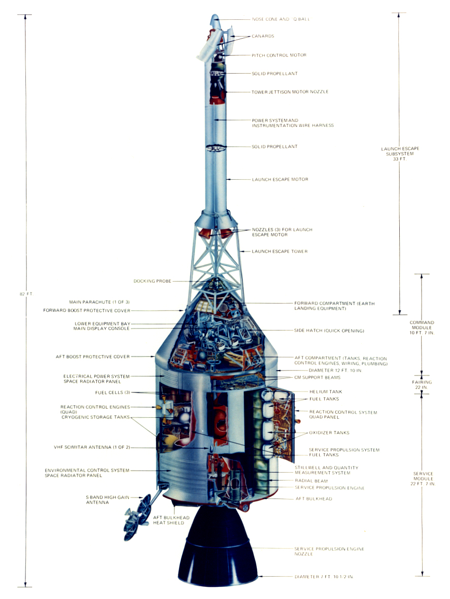
An exquisite ca. 1967-71 (total SWAG) cutaway diagram of the Apollo Command/Service Module (CSM), with Launch Escape System (LES). The image was possibly originally created for & contained within the “Apollo Spacecraft News Reference” manual. Over the course of the Apollo Program, the manual was revised several times to more accurately reflect changes, updates, additions, etc., to hardware, timelines (maybe?), etc.
As such, because of the featureless non-ribbed SM radiator panels, I think this to be an earlier/initial rendering, subsequently updated with the callouts “REACTION CONTROL ENGINES (QUAD)” and “HIGH-GAIN (DEEP SPACE) ANTENNA”. They can be seen to be affixed to the original image, likely over what was originally printed. Another version bears “RCS QUAD” and “S-BAND HIGH GAIN ANTENNA” respectively.
Who knows what other versions have? Who knows how many revisions were made? I’d expect the source material for the CSM news reference to have been primarily of NAA/NAR origin, hence the talented unidentified artist responsible to have been under their employ.
Speaking of exquisite:
heroicrelics.org/info/csm/csm-general.html#csmcanr
Credit: Mike Jetzer/heroicrelics.org
In exquisite color:
www.apolloproject.com/diagrams/csm-diagram-tempi.jpg
Credit: APOLLOPROJECT.com website
“Neil Armstrong and Edwin Aldrin will take off from the moon in the top part of their Lem, leaving the bottom part behind as their launch pad (1).”
Based on the stamped date, issued in conjunction with the flight of Apollo 11. And as part of the press release, labeled as photo no. 1. Photograph/image no. 2 of the press release is linked to below. Based on the appearance of the spacecraft, this was possibly the final/near final NAA/NAR rendering of the Apollo mission timeline ‘storyboard’.
As with those earlier renderings, I think it’s by Gary Meyer.
“APOLLO 6 ROLL OUT--------High-angle view of the Apollo 6 (Spacecraft 020/Saturn 502) stack and its mobile launch tower atop a crawler-transporter leaving the Vehicle Assembly Building on the way to Pad A, Launch Complex 39.”
Also:
www.nasa.gov/sites/default/files/thumbnails/image/9903402...
In color:
www.nasa.gov/sites/default/files/thumbnails/image/apollo_...
“LEM Cold Flow Test Site logo”
Is this “in-house” appealing or what?! I love it. It looks like it was created & rendered by one of the guys who took at least one art class in high school, or maybe the one semester/quarter at college.
For context, see/read my pointless observations accompanying the images linked to below.
If nothing else though, I’m at least connecting some obscure dots.
nyheritage.contentdm.oclc.org/digital/api/singleitem/imag...
Credit: “Cradle of Aviation Museum, Garden City, NY” website
Two versions of it are featured:
www.crewpatches.com/crewpatches_grumman.shtml
Along with the following remarks:
“An example of this patch appears on a vintage banner displayed at the Cradle of Aviation Museum at Long Island, New York.
Thanks to a letter discovered in the estate of Walter Schirra we now know that this patch was designed by a Grumman employee at the Bethpage plant in 1965. He intended it to be worn by personnel working on the LEM Propulsion systems there.”
Credit: “Crew Patches” website
An impressive photograph, ca. 1966/67 of the assembly line for F-1 rocket engine thrust chambers at North American Aviation’s Rocketdyne Division facility, Canoga Park, CA.
The number on the dolly is that of the engine on it, in this case '2053' & '2057' being visible.
And along those lines...excellent...as always:
heroicrelics.org/info/f-1/f-1-serials.html
Credit: Mike Jetzer/HEROIC RELICS website
The contemporary ‘official’ caption associated with the image:
“F-1 Assembly – Archive photo of the F-1 assembly line at Aerojet Rocketdyne’s Canoga Park, California facility.”
At:
www.rocket.com/sites/default/files/images/media/apollo50/...
Credit: Aerojet Rocketdyne website
Good Saturn engine reading:
“Excellent & rarely seen view of SA-500F Facilities Verification Vehicle stacking of the S-IVB stage, in the Transfer Aisle (I think) of the Vehicle Assembly Building (VAB), Kennedy Space Center. Two of the four areas of the SA-500F’s distinctive paint pattern are on display, comprised of the alternating black & white pattern of the forward skirt and the circumferential black (with white ‘cut-outs’) of the aft skirt. The latter being the most noticeable, even from a distance, due to its proximity to the kinda, sorta, semi- alternating, partially bi-level black & white scheme of the S-IVB aft interstage.
Additionally. Absolutely wonderful:
gwsbooks.blogspot.com/2019/07/500-f-beauty-queen-with-fee...
Credit: Wes Oleszewski/"Growing Up With Spaceflight" blog
“Aerial view of V.A.B. construction.”
An unassumingly exquisite photograph. The detail/resolution is phenomenal, let alone the subject matter. Just the overall enormity. Look at the massive girders laid out in front of the VAB - and the quantity - not to mention those already in place. The number, sizes & variety of cranes. The range of identifiable gorgeous vintage automobiles…everything from the Corvette front-and-center at the bottom, to Cadillacs, Nashes, Beetles & MORE. On the horizon to the left, you can even make out detail in the newly constructed Solid Motor Assembly Building (SMAB), part of the Integrate - Transfer - Launch (ITL) complex/facility, Cape Canaveral Air Force Station (CCAFS)! “COLBY CRANE” legible on the housing of the Launcher Umbilical Tower (LUT) hammerhead crane on the right. And more.
The body of water to the left of & behind the VAB will become the turning basin.
Pretty awesome. Nineteen Sixty-Four (1964).
“LEM MOCK-UP—A full scale mockup of the Apollo Lunar Excursion Module is shown at the Lunar Topographical Simulation Area. Astronauts and engineers will use the vehicle and area for simulations and training exercises.”
Above per the verso of one of the NM Museum of Space History photos linked to below.
I think the LEM was emplaced on the Lunar Topographical Simulation Area some time during 1965, and this certainly looks like early/initial photographic documentation after such.
It looks like there's someone inside. What looks like a right hand can be seen at the 10:30 clock position of the forward egress/ingress hatch.
Finally, what LEM is this? Is it technically a mock-up, i.e. an "M-" series? Or, although I think less likely, a training model, i.e. "TM-" series?
The Apollo Program Summary extract linked below, unfortunately, doesn't help, me at least.
In lieu of comparative photographs (other than the one following), along with well-founded skepticism and doubt associated with NASA photographic record keeping & identification, I’ll foolishly go out on a limb and call this S-IC-3…being hoisted into position or removed(?) from the S-IC Test Stand/Building 4670, Marshall Space Flight Center (MSFC), possibly in October 1966.
In support of my above, I submit the following weak evidence:
history.nasa.gov/MHR-5/part-7.htm
Specifically, the following passage:
“After successful completion of post-manufacturing checkout at the Michoud Booster Checkout Facility, the S-IC-3 stage left Michoud on September 23 and arrived at MSFC on October 1. Unloading operations began on October 3, and on that same date workmen erected the stage in the test stand. ³²⁵
325. MSFC Press Release No. 66-223, Sept. 29, 1966.”
Even more specifically, this image – it being the ‘smoking rocket’:
history.nasa.gov/MHR-5/Images/fig317.jpg
HOWEVER, odds are far greater that it’s S-IC-T, due to the fact that it was static fired multiple times in the test stand. Per Mike Jetzer’s superlative “HEROIC RELICS” website:
“A total of 18 tests were performed with the S-IC-T stage at MSFC. The first three flight stages were also static-fired in the stand, with S-IC-1 undergoing two tests and S-IC-2 and S-IC-3 each being fired once. S-IC-4 and subsequent were tested at the MTF.”
At:
heroicrelics.org/msfc/test-stand-s-ic/index.html
ALTHOUGH, what little photographic evidence I’ve found of the purported S-IC-T at the MSFC S-IC test stand, of both supposed emplacement & removal, none have evidence of thrust chambers installed.
FINALLY, the outward appearance of the S-IC probably offers a clue as to its identification, Unfortunately though, I can’t keep up with the different paint schemes of the Saturn V’s, which seemed to have been changed, at different locations, during different times of the manufacturing/testing process, and where/when/if the U.S. flag decals were applied, along with what font “USA” decal was applied. So I suppose my final determination should actually be: who the f**k knows.
“Voyager 2 obtained this high-resolution color image of Neptune's large satellite Triton during its close flyby on Aug. 25, 1989. Approximately a dozen individual images were combined to produce this comprehensive view of the Neptune-facing hemisphere of Triton. Fine detail is provided by high-resolution, clear-filter images, with color information added from lower-resolution frames. The large south polar cap at the bottom of the image is highly reflective and slightly pink in color; it may consist of
a slowly evaporating layer of nitrogen ice deposited during the previous winter. From the ragged edge of the polar cap northward the satellite's face is generally darker and redder in color. This coloring may be produced by the action of ultraviolet light and magnetospheric radiation upon methane in the atmosphere and surface. Running across this darker region, approximately parallel to the edge of the polar cap, is a band of brighter white material that is almost bluish in color. The underlying topography in this bright band is similar, however, to that in the darker, redder regions surrounding it. The Voyager Mission is conducted by JPL for NASA's Office of Space Science and Applications.”
Also:
“Voyager 2 image showing the southern hemisphere of Triton. At 2,700 km diameter, Triton is Neptune's largest satellite. This image was made using about a dozen Voyager 2 frames. The large, pinkish colored south polar cap is at the bottom of the image. North of the cap the surface is generally darker and redder in color. This area exhibits a plethora of unusual morphologic features, including the long lineations at the center of the frame.”
With the image, from/at:
nssdc.gsfc.nasa.gov/imgcat/html/object_page/vg2_p34764.html
Credit: NSSDCA website
And:
“Voyager 2 passed by Triton about 5 hours after skimming within 5000 kilometers (3000 miles) of the cloud tops of Neptune. Triton is only slightly smaller than Earth’s Moon and is one of the most unusual objects encountered during all the Voyager planetary flybys. This image is a digital mosaic of 12 individual images, with color information added from lower-resolution frames. The large south polar cap at the bottom of the image is a slowly evaporating layer of frozen nitrogen. The dark streaks on the polar cap are probably deposits resulting from the expulsion of frozen nitrogen that suddenly changed to the vapor phase, essentially a nitrogen eruption. Voyager data showed that Triton is extremely cold (daytime temperature of 37 K, or –400°F), extremely bright (reflecting nearly 100% of the sunlight incident upon it), and has a very tenuous atmosphere of nitrogen and methane (with a surface pressure 10 millionths of Earth’s atmosphere at sea level). The darker, slightly redder color beyond the polar cap may result from radiation effects on methane included within the ice. The ridges and depressions visible away from the polar cap are probably due to the deformation of water ice. Triton is essentially the same size and density as Pluto so it is possible that the surface of Pluto may look somewhat like Triton, but Pluto remains the only planet not yet visited by a spacecraft.
Mosaic of Voyager 2 images (Press Release P-34764).”
Also with the image, from/at:
www.lpi.usra.edu/publications/slidesets/ss_tour/slide_38....
Credit: LPI website
The Golden Gate Bridge glows orange against the predawn darkness, its iconic towers and suspension cables illuminated while fog wraps around the Marin Headlands beyond.
Photographed from Twin Peaks looking west, this panoramic view captures San Francisco in that liminal moment between night and day when the city's lights still sparkle but natural light begins painting the sky in subtle gradients of blue and pink.The bridge itself commands the middle distance, its distinctive International Orange color standing out even in low light thanks to the decorative lighting that traces its towers and cables. Those twin towers rising 746 feet above the water have become synonymous with San Francisco itself, perhaps the most photographed and recognizable bridge in the world.
Opened in 1937 after four years of construction, the Golden Gate Bridge was an engineering marvel that many said couldn't be built—spanning 4,200 feet across the strait connecting San Francisco Bay to the Pacific Ocean, withstanding powerful currents, deep water, and frequent fog.
The foreground reveals San Francisco's residential fabric spreading across the city's western neighborhoods. This elevated vantage from Twin Peaks—roughly 900 feet above sea level—allows you to see the gridded street pattern, the mix of housing types, and the tree canopy that softens the urban density. The Richmond and Sunset districts dominate this western side of the city, their orderly blocks of single-family homes, small apartment buildings, and neighborhood commercial corridors representing post-earthquake development and the city's mid-century suburban expansion within city limits.
Look at how the city lights create different patterns. Bright commercial zones—likely the Richmond District's Geary Boulevard and the Sunset's Irving Street—cut horizontal paths through residential areas where warmer, more diffuse lighting suggests homes and local businesses. The Presidio's darker areas on the left preserve the former military base's forest and open space, while Golden Gate Park's dark band running through the middle of the frame shows how that three-mile-long urban forest creates a natural break in the city's development pattern.
The atmospheric conditions are quintessentially San Francisco. That thick bank of fog sitting over the Marin Headlands and threatening to spill through the Golden Gate represents the marine layer that gives the Bay Area its temperate climate and famously unpredictable weather.
The bridge's towers emerge from the fog like sentinels, while the low cloud deck above creates a muted sky that will likely give way to sunshine or remain overcast depending on how that marine layer behaves over the next few hours.The bay waters beyond the bridge show as a dark band separating San Francisco from Marin County.
This strait has always been treacherous—strong tidal currents, cold water temperatures, and frequent fog made navigation challenging long before the bridge existed. Ships entering San Francisco Bay had to time their passage carefully, and countless vessels met disaster on the rocks.
The bridge transformed regional transportation, connecting San Francisco to the North Bay and beyond, enabling suburban development in Marin and Sonoma counties that fundamentally reshaped the region's geography.
From this elevated perspective, you can appreciate San Francisco's unique urban form. This is a city that refused to be limited by its hilly topography. Those neighborhoods spreading across the western slopes represent generations of San Franciscans who carved streets into steep hillsides, built homes on challenging lots, and created communities in every available space. The density is impressive—this is one of America's most densely populated cities—yet the scale remains human. Few high-rises interrupt the horizon, preserving view corridors and maintaining neighborhood character.
The lighting in this photograph creates layers of depth and atmosphere. The cool predawn sky gradates from darker blue overhead to lighter tones near the horizon, while the warm city lights provide contrast and detail in the foreground. The bridge's orange glow becomes the visual anchor, drawing the eye across the frame while the scattered lights of Marin communities beyond suggest the broader metropolitan region connected by this single span.
San Francisco's relationship with the Golden Gate Bridge is complicated. It's simultaneously the city's most beloved symbol and a barrier some never cross. The bridge connects but also divides—creating a psychological boundary between city and suburbs, between urban San Francisco and the less dense communities to the north.
For tourists, it's a must-see attraction. For locals, it's infrastructure—a commute route, a running path, a beloved but familiar landmark that becomes invisible through daily exposure until you see it like this, at dawn, and remember why people photograph it obsessively.
“APOLLO 6 ROLL OUT-----The Apollo 6 (Spacecraft 020/Saturn 502) stack and its mobile launch tower atop a crawler-transporter moving from the Vehicle Assembly Building toward Pad A, Launch Complex 39.”
The ENTIRE Apollo PROGRAM: Over-budget & on-time.
SLS (JUST the ROCKET): Way way way over- budget & way way way late.
Sign of the times.
Credit: Internet Archive website
A wonderful ca. 1966-69 NASA artist’s concept depicting LM ascent stage liftoff from the moon.
Fortunately, the signature is visible, and it’s by Lois A. Smith! A WIN!
I believe the depiction of the lunar terrain, and of course the LM, may allow me to identify other works by her. If so, outstanding.
I didn’t know Epson made photographic paper. And it’s a heavier weight than I would’ve expected. An unexpected & pleasant surprise.
A gorgeous, even if somewhat over-the-top depiction of, what to me looks a lot like a Hubble servicing mission. Note the non-tethered MMU-wearing Astronauts, representing the heady & all too cavalier vision of what future EVAs would look like. Note also that the orbiter is without the Remote Manipulator System arm…hmm.
Disappointingly/per SOP, the NASA photo whoevers botched the layout of the image; to include the ‘landscape’ orientation and the excessive cropping, lopping off half of the shuttle & half of HST’s aperture door and, in the process, the artists’ signatures.
The complete image was featured on the cover of the 2015 Winter Issue of “Pulsar”, the bi-annual newsletter of the International Association of Astronomical Artists (IAAA), at:
iaaa.org/CygnusX1/wp-content/uploads/2021/01/Pulsar-2015-...
Credit: IAAA website
Within the newsletter, per the artist responsible, Rick Sternbach:
“Science Digest, Astronomy, and Sky & Telescope all featured this painting of the HST done as a collaboration between myself and Don Dixon. Extensive use of airbrush and acrylics, a similar rendering style, and detailed CAD drawings from Lockheed Sunnyvale allowed us to produce this orbital view a few years before Hubble was launched.”
With a flipped "order of billing", reference to it being Perkin-Elmer copyrighted & dated 1984. ¯\_(ツ)_/¯:
www.cosmographica.com/spaceart/Technology/index.html#img=...
Credit: Cosmographica website
Regardless, as a card-carrying member of IAAA’s peanut gallery - if you have even the slightest interest in this type of artwork - I highly recommend taking a look at the following gallery. I can attest that IAAA members are conscientious & consummate professionals constantly striving to create meaningful works:
“Pad 39A MSS pullback from 503 Saturn plus xenon lamps affect off pad area.”
A stunning photograph, despite the color shift & emulsion artifacts, of THE rocket of ALL rockets - the Saturn V.
The historic flight of Apollo 8 commenced the following day, December 21, 1968.
Nineteen Sixty Eight…1968.
As of this ‘writing’, that’s nearly this many years ago:
IIIII IIIII IIIII IIIII IIIII IIIII IIIII IIIII IIIII IIIII III
That’s A LOT.
“SPS CONSTRUCTION: SECOND PASS”
No signature. Craig Kavafes?
Fortunately, the image is in Fig. 2 of the following, a 1980 paper entitled “SPECIFIC SPS CONSTRUCTION STUDIES: CONSTRUCTION TASKS-CONSTRUCTION BASE”, by Ronald W. McCaffrey, Grumman Aerospace Corporation, Bethpage, N.Y.
The scale & enormity of the proposed concept is mind boggling…no wonder it was never built, despite the envisioned utopian energy end state.
“ABSTRACT
This paper discusses a concept for building the 5000 MW reference Solar Power Satellite in earth orbit, based on recent work performed for NASA/JSC under contract to Boeing, on the SPS System Definition Study, and on related work performed under Grumman IRAD.
INTRODUCTION
Several concepts have been recently described on how to build the Solar Power Satellite (SPS) in space. These concepts entail fabrication and assembly of the entire satellite in geostationary earth orbit (GEO), at 35,800 km altitude, as well as partial construction at an intermediate low earth orbit (LEO) followed by final assembly in GEO. A concept for building the entire 5000 MW reference satellite in GEO is discussed below. Construction base operations needed to produce one SPS every six months are described and areas for near term technology development are identified.
GEO CONSTRUCTION BASE
The GEO Base concept shown in Fig. I was developed to build the 5000 MW reference SPS system, which uses silicon solar cells with no concentration. This 4 Bay End Builder construction base was selected for further definition in the Phase 2 study because it offered greater production capability than other concepts investigated in Phase I. The GEO construction base is configured to avoid free flying facilities and/or assembly methods. As a result, the base has contiguous facilities for concurrent assembly and subsequent mating of the satellite energy conversion system and its power transmission antenna.
The overall base is 3.44 km wide x 3.65 km long x 0.9 km deep. The base structure serves as an assembly jig which houses the required construction equipment and supports the emerging satellite during all phases of construction. The top deck of the GEO base, level J, provides facilities for cargo docking/unloading and distribution, crew quarters, command and control operations, orbital transfer vehicle (OTV) docking and servicing, and SPS maintenance support complex. Base electrical power and flight control subsystems are also provided so that all work facilities and crew support facilities can operate, as needed.
GEO CONSTRUCTION OPERATIONS
The personnel needed to activate the 4 Bay End Builder Construction Base must travel first by means of the Shuttle to LEO and finally, by means of an orbital transfer vehicle (OTV) which operates from the LEO base.
The 4 Bay End Builder Base assembles the 5 GW reference Solar Power Satellite entirely in geosynchronous orbit, as shown by the construction sequence shown in Fig. 2.
[OF WHICH THE POSTED PHOTO IS A PART OF]
The 8 bay wide satellite energy conversion system is constructed in two successive passes on one side of the base, while the microwave antenna is assembled on the other side of the base. During the first construction pass, the GEO base builds one-half of the energy conversion system, a 4 bay wide strip by 16 bays long. When this part of the satellite has been constructed, the base is indexed back along the edge of the structure to the first end frame. During the second construction pass [THE POSTED PHOTO], the remaining 4 bay wide strip is attached directly to the assembled satellite systems. Throughout the construction operation, SPS construction materials and components will be delivered by large electrical orbital transfer vehicles (EOTV). These vehicles will station-keep at least 1 km away, while special cargo tugs transfer material pallets. GEO base crews will, of course, also be rotated as needed. At the end of the second pass, the base is then indexed sideward to mate the antenna with the center line of the energy conversion system. After final test and check out, the base separates from the satellite and is transferred to the next orbital position for SPS construction.
The reference scenario requires that one 5 GW satellite is to be constructed every six months for 30 years. In order to carry out this program, nearly 450 space workers would be needed on two daily shifts (10 hours each) to perform construction, base support, maintenance, safety and base management operations.
BASE CONSTRUCTION SYSTEM
The end builder construction system described above uses ten synchronized beam machines to automatically fabricate continuous longitudinal beams for the energy conversion system. Lateral and diagonal members of the structural assembly are fabricated with three mobile beam builder substations. The assembly sequence, as shown in Fig. 3, begins with assembly of the first end frame and its attachment to the longitudinal members. This frame is automatically indexed away as the synchronized beam builders fabricate the required length of longitudinal beam to complete the structural bay. During these operations, solar array blankets and power busses are installed in parallel. For example, Fig. 4 shows how the solar array blankets might be temporarily anchored to the base so that they can be automatically deployed during longitudinal beam building operations. The illustration also shows two cherry pickers prepared to handle and connect opposite ends of a 667.5 m solar array support beam to the SPS frame after it emerges from the 12.7 m beam builder.
NEAR TERM TECHNOLOGY EMPHASIS
Constructing the large skeletal structure of the energy conversion system (5.35 km x I0.78 km x 0.47 km), including the installation and check out of its subsystems, will not be an easy task. While plausible concepts have been derived and limited development work has been started on auto-fabrication, a great deal of additional analysis and technology development work needs to be done before we can have confidence in the practicality of this process. For example, future dynamic analysis of the satellite construction process may show that some techniques can impose stringent load conditions on the elements of the satellite, while other techniques do not. As the reference SPS concept matures, all aspects of the construction approach must be analyzed further and periodically re-examined by considering technology issues related to the satellite design, orbit construction location, base facilities, crew and operations. These efforts should also be supported by laboratory investigations of SPS construction issues related to structural fabrication and assembly, construction support and subsystems assembly methods. This effort should be focused on developing technology which can lead toward SPS beam builders, SPS beam handling, subsystem assembly, mating of large space structures and techniques for deploying/installing SPS non-structural subsystems. Subscale prototype demonstrations should be used, wherever practical.”
At:
ntrs.nasa.gov/citations/19820014858
Additional pertinent reading, to include the image:
nss.org/wp-content/uploads/SSP-Boeing-CR160480-1979-Phase...
Credit: NSS website
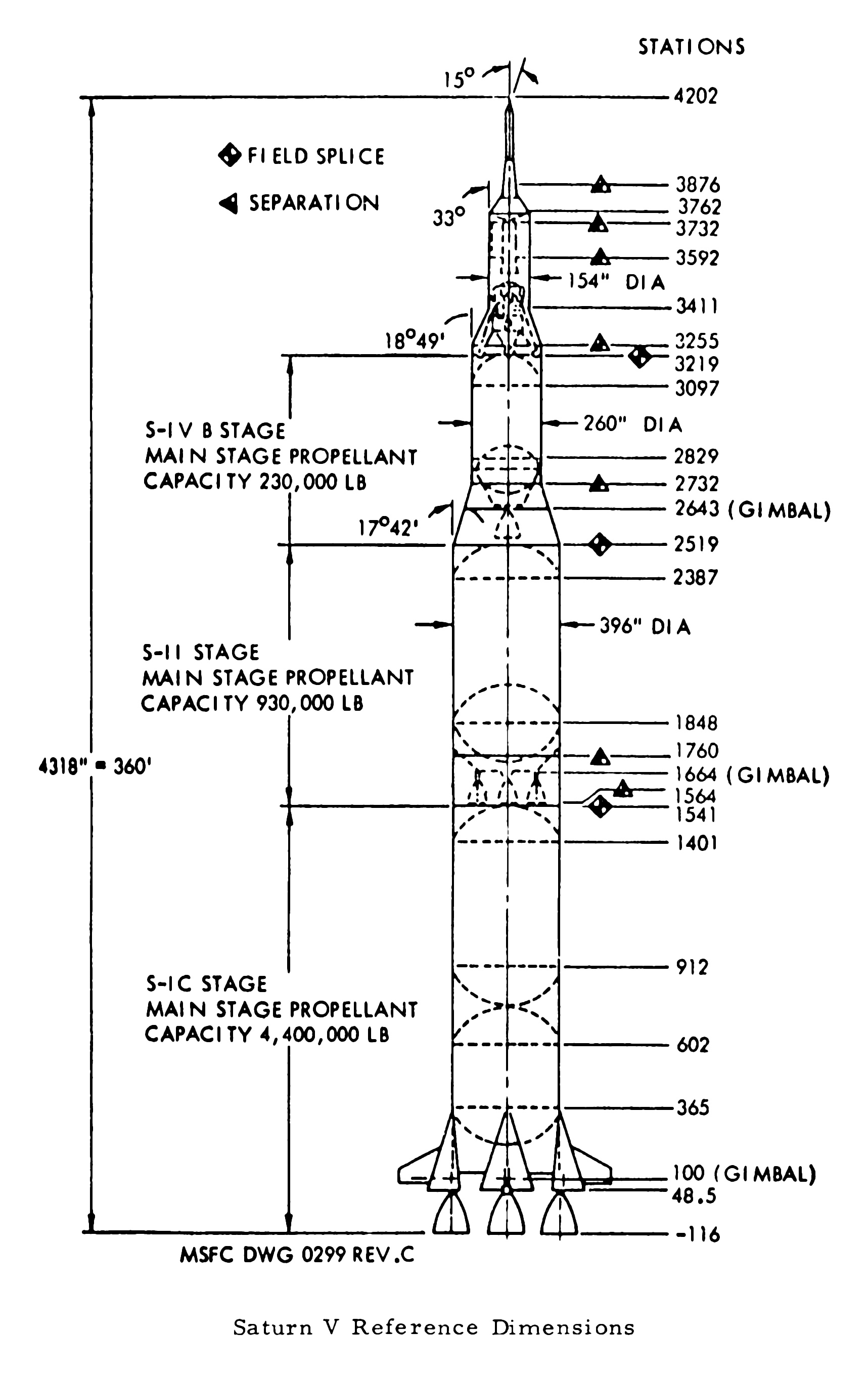
"Apollo-4 Configuration"
"Sta" refers to station numbers...which appear to be a standardized bottom-to-top linear reference system, in inches, of the launch vehicle’s ‘planes’ of attachment(?), separation(?) and (thanks to Mike Jetzer)…gimbal.
I think I've also seen station numbers associated with/to levels/points on either the Mobile Service Structure (MSS) or Launcher Umbilical Tower (LUT). Maybe even both? If so, reasonable to assume they correspond with those of the vehicle??? Then again, it may just be a concocted memory on my part.
Fortunately, and commensurate with the superb site it is, the following excerpt, along with additional graphics, sheds light on the ‘mystery’:
“The station numbers are at right. Marshall Space Flight Center station numbers are in inches and are defined such that station 100 is the gimbal plane of the engines. This scheme seems to have started with the Jupiter missile (the first ABMA missile with an engine with gimbal capability; the Jupiter's S-3D engine was 100 inches tall from the exit plane to the gimbal plane) and continued on up to the Saturn V. This leads to the somewhat unusual need, in the case of the much-larger F-1 engine, for negative station numbers.”
At:
heroicrelics.org/info/saturn-v/saturn-v-general.html
heroicrelics.org/info/saturn-v/saturn-v-general/saturn-v-...
Both above credit: Mike Jetzer/heroicrelics.org
If correct, which I have no reason to doubt, how bizarre…to continue the “tradition”. There surely must’ve been some interesting history & background for its 'continuation'. So, station numbers seem to be attributed to MSFC. I don't get it.
Also, although I've found "field splice" in various NASA documents, it still doesn't help me understand or visualize it. So, I guess it's "duh" on my part.
SLS my Artem-ass. 😜
“STS-31 onboard photo – HST deployed”
A rarely seen image of the initial deployment of the Hubble Space Telescope (HST). Taken from one of the aft-facing flight deck windows, the close proximity & dramatic perspective indicates it to have been taken early in the deployment process.
Note the prominent dish of one of the two still retracted high-gain antennas, along with the still retracted & rolled up solar arrays along either side.
Finally, note also the abundance of handrails on HST, to facilitate the unprecedented human maintenance of the engineering marvel.
I hope so, very much:
www.nasa.gov/feature/goddard/2022/nasa-spacex-to-study-hu...
Official Grumman Aircraft Engineering Corporation (GAEC) photo of the ubiquitous (at that time) and coveted (to this day) desktop model of the Lunar Excursion Module, manufactured by Precise Models, Elyria, Ohio. Appropriately enough, where I grew up.
“This image was returned by the Voyager 2 spacecraft on July 3, 1989, when it was 76 million kilometers (47 million miles) from Neptune. The planet and its largest satellite, Triton, are captured in the field of view of Voyager's narrow-angle camera through violet, clear and orange filters. Triton appears in the lower right corner at about 5 o'clock relative to Neptune. Recent measurements from Voyager images show Triton to be between 1,400 and 1,800 kilometers (about 870 to 1,100 miles) in radius with a surface that is about as bright as freshly fallen snow. Because Triton is barely resolved in current narrow-angle images, it is too early to see features on its surface. Scientists believe Triton has at least a small atmosphere of methane and possibly other gases. During its closest approach to Triton on August 25, 1989, Voyager should provide high-resolution views of the moon's icy surface and reveal whether Triton's atmosphere has clouds. JPL manages the Voyager Project for NASA's Office of Space Science and Applications.
pg. 57-5”
The cited page number possibly of some NASA/JPL documentation on which the image was featured?
photojournal.jpl.nasa.gov/catalog/PIA01491
Credit: JPL Photojournal website
“This picture shows a region of the southern hemisphere extending from the Great Red Spot to the south pole. The white oval is seen beneath the Great Red Spot, and several small scale spots are visible farther to the south. Some of these organized cloud spots have similar morphologies, such as anticyclonic rotations and cyclonic regions to their west. The presence of the white oval causes the streamlines of the flow to bunch up between it and the Great Red Spot.”
Above at/from:
photojournal.jpl.nasa.gov/catalog/PIA00372
Credit: JPL Photojournal website
And…here it comes! At the “NEW” & “IMPROVED”, THE ONE & ONLY “NASA Image and Video Library” website! Oh, wait one, ONE of these things is NOT like the others.
PATHETIC, although consistently so, at least:
images.nasa.gov/details-ARC-1979-AC79-7072
From the estate of Eric Burgess, thus possibly featured as ‘Figure 5-18’ in one of his many books.
“Artist’s concept of Pioneer over Jupiter’s Red Spot.
Man will reach out beyond Mars to take the first close look at the planet Jupiter on the mission of the unmanned Pioneer F spacecraft, to be launched by the National Aeronautics and Space Administration from Cape Kennedy, Fla., between Feb. and March 1972. The trip to Jupiter will last less than two years, for most launch dates, with most arrival times before Dec. 31, 1973. Jupiter is a spectacular planet. It appears to have its own internal energy source and is so massive that it is almost a small star. It may have the necessary ingredients to produce life. Its volume is 1,000 times that of Earth, and it has more than twice the mass of all the other planets combined. Striped in glowing yellow-orange and blue-gray, it floats in like a bright-colored rubber ball. It has a huge red “eye” in its southern hemisphere and spins more than twice as fast as Earth. Pioneer’s 13 scientific experiments are expected to provide new knowledge about Jupiter and many aspects of the outer solar system and our galaxy. It will return the first close-up images of Jupiter, and will made the first measurements of Jupiter’s twilight side, never seen from Earth.”
From the estate of Eric Burgess, and possibly featured as figure 3-3(a) in an unidentified publication by him.
Although disappointingly, wrongly, yet as expected, acknowledged nowhere within the following document, I’m quite certain that this beautiful work is by Rick Guidice. As the title/header image for chapter 4, along with the title/header artist’s concepts within the publication confirmed to be by Mr. Guidice, a reasonable extrapolation. Besides, it was probably contractually agreed to by Mr. Guidice & NASA.
In color:
images.nasa.gov/details-ARC-1972-AC72-1354
Along with others. Always exceptional:
e05.code.blog/category/nasa-un-crewed-programs/pioneer/
Credit: numbers station blog
“Saturn SA-1
Open house – 1961
Manufacturing Engineering Div
Marshall Space Flight Center
Huntsville, Alabama”
The above is beautifully handwritten by pen, in cursive, on the verso. Obviously by someone intelligent, articulate, possessing excellent penmanship and MOST importantly, ‘in the know’. Therefore, SA-1 it is. Which is what I assumed, despite not a single bit of documentation, etc., that I’ve come across that clearly states such.
Several (of the few) sources have namby-pamby descriptions/wording of the iconic views of the rocket in this horizontally ‘assembled’ & displayed state – that can be interpreted to imply that it’s SA-1…kinda/sorta/maybe.
But, if it's not...oh well. At least I made a legitimate attempt. Which is more than I can say about those whose responsibility it was/should’ve been.
The “Space Launch Report” website, the LONE site which actually referred to it as SA-1 is history, the domain having expired. A HUGE loss for someone such as myself, or anyone else conscientiously attempting to accurately catalog & preserve NASA photographic history…which obviously exceeds their ability/capability.
The caption affixed to another very similar black & white NASA-MSFC issued photograph, date stamped “JUL 7 ‘61” reads as follows:
An estimated 45,000 to 50,000 persons streamed through the George C. Marshall Space Flight Center, NASA, during the Center's "Space Day" open house, commemorating the first anniversary of the establishment of the Center. In this picture, visitors view a three-stage Saturn C-1 in an assembly hangar. This rocket is identical to the first Saturn which will be launched later this year.
And finally, from the May 1974 iteration of “AN ILLUSTRATED CHRONOLOGY OF THE NASA MARSHALL CENTER AND MSFC PROGRAMS 1960-1973”:
An estimated 45,000 to 50,000 "Space Day" visitors attended MSFC's first open house on July 1. Attending were such national figures as the NASA Administrator James E. Webb; the Director of NASA Launch Vehicle Programs, Maj. Don Ostrander; and numerous other national state, and local dignitaries. Most of the visitors observed one of the four Saturn H-1 engine static firings during the day.”
A rare, delightful unicorn containing valuable (IMHO) historical information, and brimming with wonderful nostalgia. And it’s on that exquisite super-duper smooth glossy film-like ‘paper’. You really gotta see/feel it to appreciate it…seriously.
The two exaggeratedly rectangular, tripod-mounted cameras (to the lower right) look to be, to me, Polaroid Pathfinders (110/110A/110B/120?), or 800’s maybe? It even looks like the fellow is either loading film or about to pull an exposed ‘shot’ out of one of them.
camerapedia.fandom.com/wiki/Polaroid_Pathfinder
Credit FANDOM/CAMERAPEDIA website
Finally, note the congregation of primarily males, their attention focused on the fetching young lady wearing the “SPACE(?) PRINCESS” sash. And to her right appears to be a queen and another sash-wearing “SPACE(?) PRINCESS”. So, obviously, the queen and her court…possibly from an on-site(?) MSFC parade earlier in the day.