View allAll Photos Tagged efficient.
Drawing is a form of visual art in which a person uses various drawing instruments to mark paper or another two-dimensional medium. Instruments include graphite pencils, pen and ink, inked brushes, wax color pencils, crayons, charcoal, chalk, pastels, various kinds of erasers, markers, styluses, various metals (such as silverpoint) and electronic drawing.
A drawing instrument releases small amount of material onto a surface, leaving a visible mark. The most common support for drawing is paper, although other materials, such as cardboard, plastic, leather, canvas, and board, may be used. Temporary drawings may be made on a blackboard or whiteboard or indeed almost anything. The medium has been a popular and fundamental means of public expression throughout human history. It is one of the simplest and most efficient means of communicating visual ideas.[1] The wide availability of drawing instruments makes drawing one of the most common artistic activities.
In addition to its more artistic forms, drawing is frequently used in commercial illustration, animation, architecture, engineering and technical drawing. A quick, freehand drawing, usually not intended as a finished work, is sometimes called a sketch. An artist who practices or works in technical drawing may be called a drafter, draftsman or a draughtsman.[2]
Drawing is one of the major forms of expression within the visual arts. It is generally concerned with the marking of lines and areas of tone onto paper/other material, where the accurate representation of the visual world is expressed upon a plane surface.[3] Traditional drawings were monochrome, or at least had little colour,[4] while modern colored-pencil drawings may approach or cross a boundary between drawing and painting. In Western terminology, drawing is distinct from painting, even though similar media often are employed in both tasks. Dry media, normally associated with drawing, such as chalk, may be used in pastel paintings. Drawing may be done with a liquid medium, applied with brushes or pens. Similar supports likewise can serve both: painting generally involves the application of liquid paint onto prepared canvas or panels, but sometimes an underdrawing is drawn first on that same support.
Madame Palmyre with Her Dog, 1897. Henri de Toulouse-Lautrec
Galileo Galilei. Phases of the Moon. 1616.
Drawing is often exploratory, with considerable emphasis on observation, problem-solving and composition. Drawing is also regularly used in preparation for a painting, further obfuscating their distinction. Drawings created for these purposes are called studies.
There are several categories of drawing, including figure drawing, cartooning, doodling, free hand and shading. There are also many drawing methods, such as line drawing, stippling, shading, the surrealist method of entopic graphomania (in which dots are made at the sites of impurities in a blank sheet of paper, and lines are then made between the dots), and tracing (drawing on a translucent paper, such as tracing paper, around the outline of preexisting shapes that show through the paper).
A quick, unrefined drawing may be called a sketch.
In fields outside art, technical drawings or plans of buildings, machinery, circuitry and other things are often called "drawings" even when they have been transferred to another medium by printing.
History[edit]
Drawing as a Form of Communication Drawing is one of the oldest forms of human expression, with evidence for its existence preceding that of written communication.[5] It is believed that drawing was used as a specialised form of communication before the invent of the written language,[5][6] demonstrated by the production of cave and rock paintings created by Homo sapiens sapiens around 30,000 years ago.[7] These drawings, known as pictograms, depicted objects and abstract concepts.[8] The sketches and paintings produced in prehistoric times were eventually stylised and simplified, leading to the development of the written language as we know it today.
Drawing in the Arts Drawing is used to express one's creativity, and therefore has been prominent in the world of art. Throughout much of history, drawing was regarded as the foundation for artistic practise.[9] Initially, artists used and reused wooden tablets for the production of their drawings.[10] Following the widespread availability of paper in the 14th century, the use of drawing in the arts increased. At this point, drawing was commonly used as a tool for thought and investigation, acting as a study medium whilst artists were preparing for their final pieces of work.[11][12] In a period of artistic flourish, the Renaissance brought about drawings exhibiting realistic representational qualities,[13] where there was a lot of influence from geometry and philosophy.[14]
The invention of the first widely available form of photography led to a shift in the use of drawing in the arts.[15] Photography took over from drawing as a more superior method for accurately representing visual phenomena, and artists began to abandon traditional drawing practises.[16] Modernism in the arts encouraged "imaginative originality"[17] and artists' approach to drawing became more abstract.
Drawing Outside the Arts Although the use of drawing is extensive in the arts, its practice is not confined purely to this field. Before the widespread availability of paper, 12th century monks in European monasteries used intricate drawings to prepare illustrated, illuminated manuscripts on vellum and parchment. Drawing has also been used extensively in the field of science, as a method of discovery, understanding and explanation. In 1616, astronomer Galileo Galilei explained the changing phases of the moon through his observational telescopic drawings.[16] Additionally, in 1924, geophysicist Alfred Wegener used illustrations to visually demonstrate the origin of the continents.The medium is the means by which ink, pigment or color are delivered onto the drawing surface. Most drawing media are either dry (e.g. graphite, charcoal, pastels, Conté, silverpoint), or use a fluid solvent or carrier (marker, pen and ink). Watercolor pencils can be used dry like ordinary pencils, then moistened with a wet brush to get various painterly effects. Very rarely, artists have drawn with (usually decoded) invisible ink. Metalpoint drawing usually employs either of two metals: silver or lead.[20] More rarely used are gold, platinum, copper, brass, bronze, and tinpoint.
Paper comes in a variety of different sizes and qualities, ranging from newspaper grade up to high quality and relatively expensive paper sold as individual sheets.[21] Papers can vary in texture, hue, acidity, and strength when wet. Smooth paper is good for rendering fine detail, but a more "toothy" paper holds the drawing material better. Thus a coarser material is useful for producing deeper contrast.
Newsprint and typing paper may be useful for practice and rough sketches. Tracing paper is used to experiment over a half-finished drawing, and to transfer a design from one sheet to another. Cartridge paper is the basic type of drawing paper sold in pads. Bristol board and even heavier acid-free boards, frequently with smooth finishes, are used for drawing fine detail and do not distort when wet media (ink, washes) are applied. Vellum is extremely smooth and suitable for very fine detail. Coldpressed watercolor paper may be favored for ink drawing due to its texture.
Acid-free, archival quality paper keeps its color and texture far longer than wood pulp based paper such as newsprint, which turns yellow and become brittle much sooner.
The basic tools are a drawing board or table, pencil sharpener and eraser, and for ink drawing, blotting paper. Other tools used are circle compass, ruler, and set square. Fixative is used to prevent pencil and crayon marks from smudging. Drafting tape is used to secure paper to drawing surface, and also to mask an area to keep it free of accidental marks sprayed or spattered materials and washes. An easel or slanted table is used to keep the drawing surface in a suitable position, which is generally more horizontal than the position used in painting.
Technique[edit]
Raphael, study for what became the Alba Madonna, with other sketches
Almost all draftsmen use their hands and fingers to apply the media, with the exception of some handicapped individuals who draw with their mouth or feet.[22]
Prior to working on an image, the artist typically explores how various media work. They may try different drawing implements on practice sheets to determine value and texture, and how to apply the implement to produce various effects.
The artist's choice of drawing strokes affects the appearance of the image. Pen and ink drawings often use hatching—groups of parallel lines.[23] Cross-hatching uses hatching in two or more different directions to create a darker tone. Broken hatching, or lines with intermittent breaks, form lighter tones—and controlling the density of the breaks achieves a gradation of tone. Stippling, uses dots to produce tone, texture or shade. Different textures can be achieved depending on the method used to build tone.[24]
Drawings in dry media often use similar techniques, though pencils and drawing sticks can achieve continuous variations in tone. Typically a drawing is filled in based on which hand the artist favors. A right-handed artist draws from left to right to avoid smearing the image. Erasers can remove unwanted lines, lighten tones, and clean up stray marks. In a sketch or outline drawing, lines drawn often follow the contour of the subject, creating depth by looking like shadows cast from a light in the artist's position.
Sometimes the artist leaves a section of the image untouched while filling in the remainder. The shape of the area to preserve can be painted with masking fluid or cut out of a frisket and applied to the drawing surface, protecting the surface from stray marks until the mask is removed.
Another method to preserve a section of the image is to apply a spray-on fixative to the surface. This holds loose material more firmly to the sheet and prevents it from smearing. However the fixative spray typically uses chemicals that can harm the respiratory system, so it should be employed in a well-ventilated area such as outdoors.
Another technique is subtractive drawing in which the drawing surface is covered with graphite or charcoal and then erased to make the image.[25]
Tone[edit]
Line drawing in sanguine by Leonardo da Vinci
Shading is the technique of varying the tonal values on the paper to represent the shade of the material as well as the placement of the shadows. Careful attention to reflected light, shadows and highlights can result in a very realistic rendition of the image.
Blending uses an implement to soften or spread the original drawing strokes. Blending is most easily done with a medium that does not immediately fix itself, such as graphite, chalk, or charcoal, although freshly applied ink can be smudged, wet or dry, for some effects. For shading and blending, the artist can use a blending stump, tissue, a kneaded eraser, a fingertip, or any combination of them. A piece of chamois is useful for creating smooth textures, and for removing material to lighten the tone. Continuous tone can be achieved with graphite on a smooth surface without blending, but the technique is laborious, involving small circular or oval strokes with a somewhat blunt point.
Shading techniques that also introduce texture to the drawing include hatching and stippling. A number of other methods produce texture. In addition to the choice of paper, drawing material and technique affect texture. Texture can be made to appear more realistic when it is drawn next to a contrasting texture; a coarse texture is more obvious when placed next to a smoothly blended area. A similar effect can be achieved by drawing different tones close together. A light edge next to a dark background stands out to the eye, and almost appears to float above the surface.
Form and proportion[edit]
Pencil portrait by Ingres
Measuring the dimensions of a subject while blocking in the drawing is an important step in producing a realistic rendition of the subject. Tools such as a compass can be used to measure the angles of different sides. These angles can be reproduced on the drawing surface and then rechecked to make sure they are accurate. Another form of measurement is to compare the relative sizes of different parts of the subject with each other. A finger placed at a point along the drawing implement can be used to compare that dimension with other parts of the image. A ruler can be used both as a straightedge and a device to compute proportions.
When attempting to draw a complicated shape such as a human figure, it is helpful at first to represent the form with a set of primitive volumes. Almost any form can be represented by some combination of the cube, sphere, cylinder, and cone. Once these basic volumes have been assembled into a likeness, then the drawing can be refined into a more accurate and polished form. The lines of the primitive volumes are removed and replaced by the final likeness. Drawing the underlying construction is a fundamental skill for representational art, and is taught in many books and schools. Its correct application resolves most uncertainties about smaller details, and makes the final image look consistent.[26]
A more refined art of figure drawing relies upon the artist possessing a deep understanding of anatomy and the human proportions. A trained artist is familiar with the skeleton structure, joint location, muscle placement, tendon movement, and how the different parts work together during movement. This allows the artist to render more natural poses that do not appear artificially stiff. The artist is also familiar with how the proportions vary depending on the age of the subject, particularly when drawing a portrait.
Perspective[edit]
Linear perspective is a method of portraying objects on a flat surface so that the dimensions shrink with distance. Each set of parallel, straight edges of any object, whether a building or a table, follows lines that eventually converge at a vanishing point. Typically this convergence point is somewhere along the horizon, as buildings are built level with the flat surface. When multiple structures are aligned with each other, such as buildings along a street, the horizontal tops and bottoms of the structures typically converge at a vanishing point.
Two-point perspective drawing
When both the fronts and sides of a building are drawn, then the parallel lines forming a side converge at a second point along the horizon (which may be off the drawing paper.) This is a two-point perspective.[27] Converging the vertical lines to a third point above or below the horizon then produces a three-point perspective.
Depth can also be portrayed by several techniques in addition to the perspective approach above. Objects of similar size should appear ever smaller the further they are from the viewer. Thus the back wheel of a cart appears slightly smaller than the front wheel. Depth can be portrayed through the use of texture. As the texture of an object gets further away it becomes more compressed and busy, taking on an entirely different character than if it was close. Depth can also be portrayed by reducing the contrast in more distant objects, and by making their colors less saturated. This reproduces the effect of atmospheric haze, and cause the eye to focus primarily on objects drawn in the foreground.
Artistry[edit]
Chiaroscuro study drawing by William-Adolphe Bouguereau
The composition of the image is an important element in producing an interesting work of artistic merit. The artist plans element placement in the art to communicate ideas and feelings with the viewer. The composition can determine the focus of the art, and result in a harmonious whole that is aesthetically appealing and stimulating.
The illumination of the subject is also a key element in creating an artistic piece, and the interplay of light and shadow is a valuable method in the artist's toolbox. The placement of the light sources can make a considerable difference in the type of message that is being presented. Multiple light sources can wash out any wrinkles in a person's face, for instance, and give a more youthful appearance. In contrast, a single light source, such as harsh daylight, can serve to highlight any texture or interesting features.
When drawing an object or figure, the skilled artist pays attention to both the area within the silhouette and what lies outside. The exterior is termed the negative space, and can be as important in the representation as the figure. Objects placed in the background of the figure should appear properly placed wherever they can be viewed.
Drawing process in the Academic Study of a Male Torso by Jean-Auguste-Dominique Ingres (1801, National Museum, Warsaw)
A study is a draft drawing that is made in preparation for a planned final image. Studies can be used to determine the appearances of specific parts of the completed image, or for experimenting with the best approach for accomplishing the end goal. However a well-crafted study can be a piece of art in its own right, and many hours of careful work can go into completing a study.
Process[edit]
Individuals display differences in their ability to produce visually accurate drawings.[28] A visually accurate drawing is described as being "recognized as a particular object at a particular time and in a particular space, rendered with little addition of visual detail that can not be seen in the object represented or with little deletion of visual detail”.[29]
Investigative studies have aimed to explain the reasons why some individuals draw better than others. One study posited four key abilities in the drawing process: perception of objects being drawn, ability to make good representational decisions, motor skills required for mark-making and the drawer's own perception of their drawing.[29] Following this hypothesis, several studies have sought to conclude which of these processes are most significant in affecting the accuracy of drawings.
Motor function Motor function is an important physical component in the 'Production Phase' of the drawing process.[30] It has been suggested that motor function plays a role in drawing ability, though its effects are not significant.[29]
Perception It has been suggested that an individual's ability to perceive an object they are drawing is the most important stage in the drawing process.[29] This suggestion is supported by the discovery of a robust relationship between perception and drawing ability.[31]
This evidence acted as the basis of Betty Edwards' how-to drawing book, Drawing on the Right Side of the Brain.[32] Edwards aimed to teach her readers how to draw, based on the development of the reader's perceptual abilities.
Furthermore, the influential artist and art critic John Ruskin emphasised the importance of perception in the drawing process in his book The Elements of Drawing.[33] He stated that "For I am nearly convinced, that once we see keenly enough, there is very little difficult in drawing what we see".
Visual memory has also been shown to influence one's ability to create visually accurate drawings. Short-term memory plays an important part in drawing as one’s gaze shifts between the object they are drawing and the drawing itself.[34]
Luis Rodriguez, Solar Installer, Efficient Energy of Tennessee (EETN)
Mike Butler, NABCEP Certified Solar PV Installer, HERS Rater & Energy Efficiency Specialist, Efficient Energy of Tennessee (EETN)
Jonathan Fonesca, Solar Installer, Efficient Energy of Tennessee (EETN)
Padgett Arnold, Sequatchie Cove Creamery
Alisa Farmer, Area Specialist, USDA Rural Development Tennessee
Mary Shaffer Speight, Community Relations and Grant Specialist, Efficient Energy of Tennessee (EETN)
Apart from testing the rig, we ran the boat under power to look more closely at its extraordinary performance with such a small outboard. This shot dramatically demonstrates the hull's low-drag characteristics. With 15 h.p. generating 16 knots of speed the hull creates the standard rooster tail astern, but almost no bow-wave or quarter wave. This in turn helps to explain how it achieves its speed with such a small power input.
Joint Forces Training Base home to energy-efficient headquarters
LOS ALAMITOS, Calif. -- Soldiers, family members and civilians of the 79th Sustainment Support Command will soon have a new headquarters, organizational maintenance area and acres of parking at the Joint Forces Training Base here. The work is all part of a nearly $25 million project managed by the U.S. Army Corps of Engineers Los Angeles District.
Andy Stevens of Retrofit Services Company from Rancho Cucamonga, Calif., was onsite Sept. 12 putting the finishing touches on the computerized building management system that will control the state-of-the-art energy efficient heating, ventilation, and air conditioning for the headquarters building. The system uses multiple condensers and is nearly 30 percent more efficient than systems of just five years ago.
"This one [building zone] is calling for one stage cool, fans on, temperature is 72 [degrees] in the zone and the set point is 72, so it's doing just fine," said Stevens. "You can change your occupancy status at any time, emergency override it, shut it down and we do have the chemical alert push-buttons that will close all dampers inside and out."
The alert buttons are located throughout the facility and once activated because of an attack or a release of hazardous chemicals, no air is allowed in or out of the building to protect the occupants, according to Maj. Phillip Oster, the U.S. Army Corps of Engineers Los Angeles District's Santa Ana Resident Office deputy who oversees the project.
To reduce construction costs and increase future savings, the project is using eco-friendly features, like re-cycled material, and in the case of the covered parking lots, they will generate energy with a photovoltaic system. The contract partner's quality assurance manager for the project explained the feature.
"At peak, they produce 375 KVA [kilovolt-amps]," said Edward Desmond, Cox Construction of Vista, Calif. "In theory, it's enough power to offset the footprint of the Army Reserve Center building."
While not designated a net-zero facility, the extensive use of energy efficient materials during construction will enable the photovoltaic system to actually return power to the Los Alamitos grid, off-setting the operating costs of other buildings on the base, according to Desmond.
The Energy Policy Act of 1992 mandated the use of "low flush" urinals in government facilities. This project takes it a step further with water-free urinals. The USACE Engineer Research and Development Center estimates that they pay for themselves in six-months to three years and the cost savings don't end there. All new Army construction is designed to satisfy the Silver-level standards of the Leadership in Energy and Environmental Design rating system, in accordance with the U.S. Green Building Council guidance.
According Oster, the project is in the "punch list" stage with safety officials, contractors and District project delivery teams making final inspections before furniture is installed and the customer takes possession of the ARC in October.
Efficient Basing-Grafenwoehr, which brought the Netzaberg Housing Area (pictured) to the military community, is a U.S. Army Europe initiative consisting of more than 150 projects valued at close to $1 billion designed and built over roughly 10 years. The U.S. Army Corps of Engineers Europe District managed about $100 million each year since 2001. Projects also included a shopping center, troop billet buildings, motor pools, physical fitness center, upgraded medical facilities, modern dining facility and new Army lodge, among others. For the Europe District, EB-G was not business as usual. Read about the unique project delivery methods employed by USACE at www.army.mil/-news/2010/05/05/38561-unique-project-delive... (U.S. Army Corps of Engineers photo by Rachel Goodspeed)
Efficient agricultural markets enable cross-border trade in staple foods and contribute to economic growth and food security.
Joint Forces Training Base home to energy-efficient headquarters
LOS ALAMITOS, Calif. -- Soldiers, family members and civilians of the 79th Sustainment Support Command will soon have a new headquarters, organizational maintenance area and acres of parking at the Joint Forces Training Base here. The work is all part of a nearly $25 million project managed by the U.S. Army Corps of Engineers Los Angeles District.
Andy Stevens of Retrofit Services Company from Rancho Cucamonga, Calif., was onsite Sept. 12 putting the finishing touches on the computerized building management system that will control the state-of-the-art energy efficient heating, ventilation, and air conditioning for the headquarters building. The system uses multiple condensers and is nearly 30 percent more efficient than systems of just five years ago.
"This one [building zone] is calling for one stage cool, fans on, temperature is 72 [degrees] in the zone and the set point is 72, so it's doing just fine," said Stevens. "You can change your occupancy status at any time, emergency override it, shut it down and we do have the chemical alert push-buttons that will close all dampers inside and out."
The alert buttons are located throughout the facility and once activated because of an attack or a release of hazardous chemicals, no air is allowed in or out of the building to protect the occupants, according to Maj. Phillip Oster, the U.S. Army Corps of Engineers Los Angeles District's Santa Ana Resident Office deputy who oversees the project.
To reduce construction costs and increase future savings, the project is using eco-friendly features, like re-cycled material, and in the case of the covered parking lots, they will generate energy with a photovoltaic system. The contract partner's quality assurance manager for the project explained the feature.
"At peak, they produce 375 KVA [kilovolt-amps]," said Edward Desmond, Cox Construction of Vista, Calif. "In theory, it's enough power to offset the footprint of the Army Reserve Center building."
While not designated a net-zero facility, the extensive use of energy efficient materials during construction will enable the photovoltaic system to actually return power to the Los Alamitos grid, off-setting the operating costs of other buildings on the base, according to Desmond.
The Energy Policy Act of 1992 mandated the use of "low flush" urinals in government facilities. This project takes it a step further with water-free urinals. The USACE Engineer Research and Development Center estimates that they pay for themselves in six-months to three years and the cost savings don't end there. All new Army construction is designed to satisfy the Silver-level standards of the Leadership in Energy and Environmental Design rating system, in accordance with the U.S. Green Building Council guidance.
According Oster, the project is in the "punch list" stage with safety officials, contractors and District project delivery teams making final inspections before furniture is installed and the customer takes possession of the ARC in October.
La proposta progettuale nasce e si sviluppa da valutazioni riguardanti il complesso sistema degli accessi all’area, dei percorsi pedonali e viabilistici, dalla ricerca di una corretta integrazione dell’edificio con il masterplan dell’intera zona e, non ultimo, dalla sensibilità nei confronti dei fattori climatici del contesto.
Il corpo di fabbrica è articolato in due ali, dalle forme organiche efficientemente interconnesse ed atte ad accogliere luce e verde al loro interno. La “cellula” del palazzo ad uffici si apre verso sud per dare accesso ai sistemi di circolazione pedonale legati al programma del masterplan, favorendo la compenetrazione tra edificio ed un ricco sistema a verde in continuità con il tessuto del progetto dell’intero complesso. Il piano terra, prevalentemente vetrato, minimizza l’attacco a terra del nastro di facciata ed accentua la permeabilità dell’intervento al livello degli attraversamenti pedonali favorendo il dialogo simbolico tra l’area a verde naturale situata nella zona a nord del masterplan con le aree verdi più “urbane” della zona centrale. Il locale bar presente nell’ala ovest aumenta ulteriormente l’integrazione dell’edificio con le attività e le relazioni in atto nell’intero complesso di progetto. Oltre che dal locale bar, l’accesso all’edificio avviene tramite un atrio passante posto nel punto di connessione tra le due ali nel quale si affacciano sia l’ingresso pedonale, sia l’ingresso da una zona di drop-off.
La facciata è concepita come una superficie continua, un nastro tecnologico che si sviluppa adattandosi alle diverse condizioni al contorno: la pelle dell’edificio si adatta e legge, in modo efficiente, l’incidenza del sole nelle diverse stagioni, nella costante ricerca di una efficienza ed ottimizzazione energetica. Pensato perciò come un grande filtro di luce dell’edificio, proprio per questa capacità intrinseca di adattarsi al contesto, genera ambienti nei quali è garantita un’elevata qualità abitativa in termini di comfort climatico ed illuminotecnico.
Costituzione e funzionalità dell’edificio:
L’edificio può essere considerato costituito da due ali connesse tra loro:
- l’ala est costituita da otto livelli fuori terra a destinazione uffici, un livello interrato a parcheggio e un livello “giardino” in copertura;
- l’ala ovest costituita da sette livelli fuori terra di cui sei destinati ad uffici e uno ad uso bar-ristoro al piano rialzato; completano quest’ala un piano tecnico per gli impianti in copertura e due livelli di parcheggi di cui uno seminterrato e uno interrato.
L’altezza complessiva dell’edificio è pari a 33,50 m sul fronte ovest e 30,00 m sul fronte est, mentre l’altezza utile ai fini urbanistici, misurata all’intradosso della soletta dell’ultimo piano abitabile, è di 29,35 m inferiore a quella prevista dalla sagoma limite del piano particolareggiato (29,60 m).
I livelli dell’edificio presentano un interpiano di 370 cm da pavimento finito a pavimento finito e un’altezza interna netta di 280 cm con pacchetti di soletta pari a 90 cm comprensivi di controsoffitto e pavimento galleggiante.
L’edificio sviluppa una superficie lorda di pavimento totale pari a 9.723 mq di cui 327 mq sono destinati all’area bar ed il resto ad uffici e servizi.
La conformazione tipologica-planimetrica dell’edificio permette l’insediamento di diverse tipologie aziendali consentendone l’utilizzo da parte di un unico locatario, di due locatari (mediante la suddivisione della pianta in due corpi di fabbrica autonomi e distinti) o infine di più locatari mediante la suddivisione su livelli (di 1329 mq di Slp) o semi-livelli (di 663 mq e 760 mq rispettivamente).
L’ipotesi della soluzione per bilocatario ha suggerito la possibilità di una completa divisione funzionale dell’edificio a partire dall’atrio che è studiato per poter essere frazionato in due parti con accessi distinti ed autonomi.
I blocchi servizi:
Lo schema distributivo dei piani presenta due blocchi servizi, uno per ogni ala. Ognuno di questi blocchi, contiene due vani scala, ciascuno con filtro a prova di fumo, comprendenti due ascensori di portata 12 persone / 900kg (cabina 140x150 cm, porte 90 cm) e un montacarichi di portata 13 persone / 1000.kg (cabina 100x210 cm, porte 90 cm).
Scale e ascensori sono collegati all’atrio, ai due piani di parcheggi interrati e al piano di copertura.
Tre delle quattro scale dell’edificio risultano attigue alle facciate e sono pertanto rese aperte e considerate “scale fredde”; ai fini urbanistici tali scale non rientrano nel calcolo della superficie lorda di pavimento. La quarta scala, in posizione non adiacente alla facciata, viene considerata, come previsto dal regolamento d’igiene, “scala primaria” e perciò chiusa, pur mantenendo le adeguate aperture per l’areazione naturale alla base ed in sommità come previsto dallo stesso regolamento.
Il dimensionamento ed il numero delle scale è conforme a quanto previsto alla normativa antincendio, mentre quantità e capacità degli ascensori sono misurate ai flussi di persone previsti nell’edificio che nell’ipotesi di massimo affollamento vengono stimati su una quantità di circa 900 persone.
In ognuno dei blocchi servizi sono presenti anche i servizi igienici divisi per sesso (2 per uomini, 2 per donne) più un servizio per disabile, un locale pulizie, un locale quadro elettrico, un locale dati/fonia (con rispettivi cavedi di passaggio delle reti) e un grande cavedio per le principali distribuzioni impiantistiche.
L’area uffici:
Le restanti parti del piano, che comprendono tutti gli affacci esterni dell’edificio, presentano pianta libera consentendo una notevole flessibilità di distribuzione e permettendo di creare zone open-space alternate ad uffici singoli, doppi o quadrupli in un numero molto elevato di soluzioni in grado di offrire ampio margine alle esigenze dei futuri utenti.
Il nastro continuo di facciata, assieme al passo della maglia strutturale, si relaziona con gli ambienti interni diventando il principio ordinatore capace di generare e modulare le diverse configurazioni di distribuzione interna garantendo in ognuna di esse eccellenti condizioni climatiche e di illuminamento. Il contatto con il mondo esterno e la qualità abitativa in termini di confort climatico ed illuminotecnico interno, unite alla possibilità di personalizzare le condizioni ambientali attraverso l’apertura delle finestre, sono state ricercate ai fini dell’ottenimento delle migliori condizioni di comfort psico-fisico per gli utenti.
In entrambe le ali dell’edificio la maglia strutturale presenta un modulo base di 5,70 m ed è studiata per permettere la formazione sia di locali per uffici dirigenziali o locali per uffici quadrupli di larghezza netta interna di 5,50 m, sia locali per uffici singoli di larghezza interna netta 2,70 m. La profondità di tali locali è variabile dai 5,50 m ai 6,50 m a seconda della posizione nella pianta.
Nella soluzione open-space si ha invece la possibilità di posizionamento di 3 gruppi di 6 tavoli operativi (di dimensioni 160 x 80 cm) ogni due campate strutturali. In questa soluzione, che risulta quella che determina il maggior affollamento dell’edificio, si possono contare un numero pari a 130 postazioni per ogni piano, quantità compatibile con il massimo affollamento previsto dalla normativa antincendio (132) in relazione alla larghezza delle vie d’uscita.
I percorsi di distribuzione interna orizzontale nei piani, di larghezza minima 150 cm, si svolgono in modo lineare lungo i corpi servizi, comprendendo anche gli sbarchi degli ascensori e le loro lunghezze sono commisurate alle massime distanze consentite per le vie di fuga.
Il posizionamento ed il numero delle finestre apribili, con apertura verso l’interno ad anta semplice a tutta altezza, è studiato in modo tale da garantire almeno un’apertura per ogni modulo base di 5,70 m, senza interferire con la posizione dei pilastri strutturali. Inoltre ad ogni piano, in alcune zone della pianta, sono previste due aperture per modulo base per permettere la formazione di uffici singoli di larghezza 2,70 m areati e illuminati autonomamente. Il numero e il posizionamento delle finestre apribili determina per ogni piano la massima suddivisibilità in uffici chiusi e di conseguenza la quantità e il posizionamento delle dotazioni impiantistiche necessarie per ogni livello.
I rapporti aero-illuminanti risultano soddisfatti negli uffici singoli considerando unicamente le finestre ad anta apribile mentre per gli uffici doppi o per le aree open-space sono da aggiungere ai fini del calcolo del rapporto illuminante anche i contributi dovuti alle specchiature non apribili considerando le percentuali di illuminamento determinate dalla presenza delle lamelle di legno all’interno delle vetrocamere (variabili dal 45% all’80%).
La flessibilità distributiva interna è inoltre rafforzata dall’impiego di pavimenti sopraelevati per facilitare l’accessibilità alle reti e controsoffitti ispezionabili modulari con le soluzioni di layout sopra elencate.
Nella zona di connessione tra le due ali, dove il corpo di fabbrica è più profondo, possono trovare spazio sale riunioni, locali per archivi e spazi relax. Questi ultimi si affacciano verso il fronte interno, più privato, della corte attraverso delle terrazze che via via si fanno sempre più aggettanti salendo in altezza nell’edificio e che fungono anche da protezione solare per la facciata interna esposta a sud. In corrispondenza del punto di massimo aggetto dei terrazzi sono previsti tiranti strutturali in acciaio inclinati a sostegno degli sbalzi.
Su questo fronte terrazzi e specchiature trasparenti accentuano la profondità nella corte dell’edificio.
Il basamento:
Il basamento dell’edificio è costituito da un livello uffici nell’ala est, direttamente confinante con area verde esterna, dall’atrio d’ingresso a doppia altezza e dall’area bar-ristoro, rialzata rispetto alla quota zero della strada di 2,00 m, venendosi a trovare sopra il primo livello, seminterrato, dei parcheggi.
Gli accessi all’edificio avvengono tramite l’atrio passante posto nel punto di connessione tra le due ali sul quale si attestano sia l’ingresso pedonale interno alla corte, sia l’ingresso da nord dalla zona di drop-off. Su entrambi i fronti dell’atrio sono previste bussole d’ingresso vetrate con doppia porta, direttamente affacciate sulla doppia altezza interna dell’atrio pari a 6,30 m. La bussola verso sud viene a crearsi dal prolungamento e la piegatura delle stesse superfici del basamento, in continuità con il disegno del percorso pedonale di accesso. Quella verso nord permette inoltre l’accesso controllato alla rampa pedonale interna che porta all’area bar. La conformazione dell’atrio e delle stesse bussole consente la possibilità di suddivisione dello spazio dell’atrio in due atrii separati nell’eventualità di suddivisione verticale dell’edificio per la soluzione del bilocatario.
Adiacente alla bussola nord e al bancone della reception è previsto un piccolo locale back-office utilizzabile per l’inserimento degli apparati telefonici ed eventualmente accessibile dalla stessa bussola.
Nell’ala ovest del basamento trova posto il bar servito da un bancone e un’area cucina con spogliatoio e servizi igienici per il personale dipendente. L’altezza interna netta dell’area bar è di 4,50 m. E’ presente inoltre un piccolo montacarichi per merci che mette in comunicazione la cucina con il primo livello interrato sottostante.
La punta sud dell’area bar, protendendosi verso l’area verde e gli spazi pavimentati esterni si svuota e lascia posto ad uno spazio coperto caratterizzato dalla presenza di pilastri inclinati che penetrano nella soletta in calcestruzzo a vista opportunamente sagomata per ricevere un inspessimento della parte strutturale e consentire una distribuzione dei carichi che provengono dai piani superiori. La connotazione architettonica di questo spazio caratterizza fortemente il luogo di percorso e sosta, crocevia di alcuni percorsi esterni di interconnessione tra le zone del contesto adiacente e la corte dell’edificio che passano per la terrazza del bar adibita a spazio per il pranzo all’aperto.
Il disegno della soletta, “svasata” lungo il perimetro di questa parte di edificio, si protende all’interno del bar e lungo la rampa interna fino a raggiungere la bussola d’ingresso mettendo concettualmente e visivamente in comunicazione questi spazi.
La copertura:
Il livello della copertura dell’edificio ospita una zona destinata agli impianti in corrispondenza dell’ala ovest ed uno spazio comune all’aperto sull’ala est da utilizzare come “tetto giardino”, luogo di rappresentanza dell’edificio, destinato alla sosta e lo svago potendo godere di una vista panoramica a 360° sull’intorno del progetto.
La zona impianti, racchiusa perimetralmente dalla stessa “pelle” di facciata che la rende parte integrante della composizione dell’edificio, contiene i gruppi frigoriferi, le unità di trattamento aria, gli estrattori, le pompe e l’impiantistica elettrica. Questi ultimi due impianti, così come i vani scale e ascensori che raggiungono il piano copertura, saranno coperti da una soletta mentre la restante parte sarà coperta da un grigliato frangisole di metallo che si protende anche nella zona accessibile agli utenti per creare spazi d’ombra all’aperto. Le parti non grigliate della copertura ospiteranno pannelli solari e pannelli fotovoltaici a servizio dell’edificio.
Lo spazio a tetto-giardino, pavimentato in doghe di legno, è racchiuso da un parapetto in vetro arretrato dal filo della facciata per non essere visibile dal livello del parco e contornato da un “giardino” di pietre, non praticabile, pensato in modo tale da non necessitare di manutenzione.
Sono previsti inoltre due locali deposito coperti a servizio degli spazi di copertura, accessibili dalle aree comuni praticabili.
L’allontanamento delle acque meteoriche in copertura avverrà mediante la formazione di piani con opportune pendenze e una canalizzazione centrale con pluviali collocati all’interno dei cavedi già previsti.
I parcheggi:
Sotto l’edificio sono stati collocati i parcheggi pertinenziali su due livelli di cui uno seminterrato a quota –1,40 m rispetto alla strada ed uno interrato a quota –4,60 m.
Il primo livello interrato presenta una superficie di 1297 mq con 21 posti auto e 46 posti moto, il secondo livello ha invece una superficie di 2242 mq con 55 posti auto e 23 posti moto, per un totale di 3539 mq che rispetta abbondantemente il minimo previsto per legge (2.916 mq, Legge Tognoli).
L’altezza interna netta dei due livelli è di 2,70 m tale da consentire l’eventale passaggio di impianti a soffitto.
L’accesso ai parcheggi avviene dalla strada che costeggia l’edificio ad ovest e sarà reso possibile l’ingresso alle sole auto provenienti da sud impedendo la svolta e l’attraversamento di corsia per quelle provenienti da nord. Le rampe a doppia percorrenza hanno larghezza pari 6,50 m con pendenza media pari al 15%, mentre quelle singole hanno larghezza pari a 3,30 m. I due livelli di parcheggio costituiscono un unico compartimento e per normativa dovranno essere dotati di impianto automatico di spegnimento. Le areazioni necessarie sono adeguatamente dimensionate e uniformemente distribuite.
Al secondo livello interrato sono presenti inoltre locali impianti di altezza interna 4,00 m contenenti la centrale idrica, la centrale termica, il locale ups, la cabina di trasformazione, la cabina Enel accessibile da una botola sull’esterno e, fuori dalla sagoma dell’edificio, il locale per il gruppo elettrogeno anch’esso accessibile da una propria botola.
Un locale deposito rifiuti di circa 40 mq, sufficiente a soddisfare il fabbisogno dell’intero edificio, è collocato in corrispondenza della rampa di accesso al primo livello interrato ed è accessibile agevolmente dalla strada dai mezzi della nettezza urbana.
Le aree esterne:
Le aree esterne sono studiate per forme e materiali per una corretta integrazione delle linee di progetto con il disegno generale del masterplan ed in particolare con gli spazi verdi circostanti. La corte dell’edificio aperta verso sud accoglie gli accessi e i sistemi di circolazione pedonale favorendo la compenetrazione tra edificio e il sistema a verde in continuità con il tessuto del progetto dell’intero complesso.
Lungo tutto il perimetro dell’edificio è resa possibile la circolazione agevole di un mezzo per la pulizia e la manutenzione delle facciate garantendo una fascia percorribile di 3,50 m con possibilità, in alcuni punti, di inversione di marcia dell’automezzo.
Sul fronte strada la presenza del parcheggio seminterrato genera la formazione di un muro lungo il marciapiede pedonale fino all’area di drop-off. Tale muro conterrà parte delle areazioni dei due livelli interrati e sarà trattato come muro “a verde”.
Come per l’ingresso ai parcheggi l’accesso al drop-off sarà reso possibile ai soli veicoli provenienti da sud impedendo la svolta e l’attraversamento di corsia per quelle provenienti dalla rotonda a nord.
Le finiture interne:
Gli ambienti interni delle aree ad uffici avranno un aspetto “caldo” e accogliente con particolare cura per le aree comuni e gli sbarchi degli ascensori. I materiali saranno scelti tra quelli lignei e comunque in accordo con l’aspetto caratterizzante delle facciate dell’edificio.
Le aree operative sono studiate in modo tale da consentire un alto grado di flessibilità nella scelta di tipologia di partizioni e rivestimenti da parte dell’utente finale.
I controsoffitti in pannelli di lana di vetro ad alta densità con superficie visibile dell’aspetto dell’intonaco saranno tali da garantire alte prestazioni fonoassorbenti per evitare il riverbero del rumore all’interno degli ambienti e avranno una superficie continua complanare sostenuta da una struttura modulare non in vista che consente l’ispezionabilità degli impianti a soffitto.
Dotazioni impiantistiche e illuminotecniche sono studiate in accordo con la flessibilità e la modularità del layout della pianta. I corpi illuminanti a sospensione saranno di tipo ad emissione diretta ed indiretta e saranno orientabili grazie alla possibilità della loro rotazione a 90° per potersi adattare alle esigenze distributive interne.
L’atrio d’ingresso, luogo di filtro e di passaggio avrà un’immagine legata per aspetto e materiali all’ambiente esterno, in continuità visiva e materica con gli spazi pavimentati della corte. I materiali di finitura e rivestimento saranno della famiglia di quelli lapidei e riconducibili ad un linguaggio “urbano” e di spazio pubblico favorendo il dialogo simbolico con le aree verdi e quelle più urbane della zona centrale del masterplan generale. Stessa cosa per il locale bar.
La facciata:
Le facciate dell’edificio sviluppano una superficie complessiva di circa 5600 mq suddivisi in tre tipologie principali:
- la parte principale dell’involucro, tecnologicamente avanzata, che copre un’area complessiva di circa 3340 mq illustrata di seguito;
- la parte del basamento, continua, interamente vetrata composta da una semplice vetrocamera (superficie 784 mq circa);
- la parte all’interno della corte che affaccia a sud tramite i terrazzi aggettanti, anch’essa interamente vetrata composta da una semplice vetrocamera (superficie 161 mq circa);
- le zone di affaccio dei blocchi servizi prevalentemente cieche, composte da una parete in calcestruzzo armato finita esternamente con pannello in legno rivestito da una lastra in vetro (superficie 930 mq circa), inserite nello stesso disegno dei serramenti della parte principale ai fini di garantire una continuità visiva dell’intero nastro.
Il nastro tecnologico di facciata definisce l’identità dell’edificio dialogando con il contesto naturale e urbanizzato in cui è immerso ma allo stesso tempo assume altri importanti compiti. La “pelle bioclimatica” consiste in un sistema di facciata di tipo OKAWOOD, fornito dalla ditta OKALUX®, composto da una vetrocamera nella quale sono inserite lamelle in legno di essenza ontano di spessore 11 mm a passo variabile (20 mm, 40 mm, 60 mm). Il peso dell’elemento finito è riconducibile a quello di una comune vetrocamera (circa 40 kg/mq) mentre lo spessore del pacchetto è di circa 40mm.
I serramenti dell’elemento OKAWOOD sono previsti in acciaio inox spazzolato sia per ottenere una continuità formale con la struttura portante della facciata stessa sia per consentire la realizzazione di profili più sottili soprattutto nelle zone a curvatura più stretta dove un telaio in alluminio, confrontandosi con moduli di larghezza pari a 95 o 47,5 cm diverrebbe dominante rispetto alle superfici vetrate. L’utilizzo di questa tipologia di infisso determina, al fine di evitare problemi di condensa interna, l’integrale carterizzazione del serramento verso l’interno; la soluzione prevede quindi l’accoppiamento all’acciaio di profili in legno che contribuiscono a dare un’immagine più calda agli ambienti di lavoro. Lo studio delle tessiture dell’elemento frangisole si sviluppa adattandosi alle diverse condizioni al contorno assecondando diversi parametri come l’angolo d’incidenza solare (nelle diverse stagioni), l’altezza delle parti di edificio nella corte interna che non ricevono luce diretta (sempre nelle diverse stagioni) ed il contributo spesso svantaggioso degli apporti solari. Il risultato consiste in una pelle che si adatta e si raffronta in modo efficiente con il tema della luce naturale evitando fenomeni di abbagliamento e con il tema del risparmio energetico ponderando gli apporti solari, nella costante ricerca di una efficienza ed ottimizzazione energetica ed illuminotecnica.
I serramenti che compongono l’involucro fanno parte di un abaco modulare in grado di soddisfare sia le esigenze compositive esterne sia le altrettanto importanti esigenze distributive interne rendendo di fatto la facciata il motivo ordinatore di una distribuzione flessibile ed efficiente degli spazi interni.
Nel nastro si alternano in modo non casuale, sia per la loro uniforme distribuzione che per l’integrazione con la struttura portante perimetrale, 242 serramenti apribili ad anta interamente trasparenti di un’unica dimensione pari a 95 x 320 cm (appartenente anch’essa all’abaco) per una superficie totale di 735 mq.
Lo studio modulare della facciata non si limita alla definizione dell’abaco precedentemente accennato ma anche alla possibilità di tagliare la facciata con una serie di giunti verticali continui scomponendo la pelle esterna in strisce sempre modulari (3M,4M,5M.....con M pari a 95cm) in stretta relazione con la fruibilità e la flessibilità interna degli spazi e garantendo una più agevole messa in opera. La larghezza delle strisce modulari varia a partire da 3M fino ad arrivare a 11M (con l'eccezione di 4 piccole strisce, formate da 3 mezzi moduli, di larghezza complessiva pari a 1,5M poste nei punti dove la pelle necessita di raggi di curvatura molto bassi). Individuate le misure e le rispettive quantità delle diverse strisce modulari è stato creato un abaco di soluzioni che permette di mantenere l’iniziale idea compositiva della facciata semplicemente affiancando e alternando i componenti del nuovo macro-abaco così creato.
Energy efficient solar screens offered by Screenmobile block up to ninety percent of the sun's radiant heat before it reaches window glass and can help reduce a homeowner's utility bills up to fifty percent. Lower electric usage, protect furnishings, hall hangings, carpet and yourself from harmful UV rays. You Call, We Screen. Screenmobile.
The Green Concept Home is a custom house designed and built by Modus V Studio Architects. This custom home was built with Premier Structural Insulated Panels, SIPs, walls and roofing. Premier SIPs provide a energy efficient and tight building envelope to help get your building to the uptmost green capacity.
2776 square feet of 6" wall panels
2296 square feet of 10" roof panels
This 2,840 sq.ft contemporary house, completed in October 2010, is located in the Greenwich Crest neighborhood in Bellevue, WA. This project aims to implement many concepts of green designs to create a holistic and sustainable way of life, without sacrificing functionality, style, comfort and cost.
The Green Concept Home is the first single-family residence in Bellevue, WA, registered under the internationally recognized “LEED for Homes” green certification program. The project is also registered under the regionally recognized “Built Green” program.
The goal of this website is to share information and our experience in order to encourage more green buildings in the future. We welcome you to tell us your thoughts, knowledge and experience and to join us in one of our upcoming green tours or open houses.
Although many fine “green” demonstration houses have already been built throughout the country, there needs to be many, many more of them, until there are enough so that virtually everyone has a chance to experience them.
Architect: Modus V Studio Architects- www.modusvarchitects.com/
For more information: www.greenconcepthome.com/
More information on Structural Insulated Panels: www.pbssips.com
Private 5 acre estate with efficient custom home – For Sale By Owner: $998,000
In the mountains just mauka of the heart of Kona Town you find nestled a small arts community called Holualoa…There’s not much to Holualoa, a blink of the eye your past it driving by the Pink Kona Hotel built in 1926 (http://www.city-data.com/picfilesc/picc5136.php), or our small post office saying Aloha to Joy or Tom the Post Master…or quite simply going to the old movie theater on Saturday night for free. And let’s not forget our excellent Holualoa Elementary School built in 1897…this is “our” little piece of heaven away from the hustle and bustle of the world’s problems.
Hualalai Farms is a gated community with mostly 5 acre parcels of world famous “Kona Coffee”. And it is good! We’re an old community by most standards up here with a fine group of quiet folks that enjoy the peaceful life of gentlemen farmers, waving to one another as we pass on the road.
My journey led me here in 1989, but it’s time to move on to a new adventure, and my little piece of solitude is available for sale. I moved into this house which I built for my family in February of 2009. For all intents and purposes it’s new. I haven’t ripped out the old Ohia trees with their beautiful Lahua Blossoms. I enjoy the privacy, and watching the sun rise over Mauna Loa in the mornings, and the cruise ships passing by below.
I designed this home and property to be efficient with low maintenance, but additional growth or changes are easy to do. If you think you’d be interested in my slice of the world then by all means email me. I’d be more than happy to call you if you forward your telephone number. If you have SKYPE on your computer we can even walk around the house and property.
1. 2128 sq ft total (1264 sq ft living)
2. 3 Car garage, 864 sq ft (1 bay divided by wall/door-currently den/office, but could be converted easily to separate efficiency apartment)
3. 200 amp service for household
4. All walls interior/exterior Corning Insulation
5. Windows “Hurd” Thermal Double Paned Aluminum Clad Douglas Fir with minimum 6 hand lacquered coats
6. Cabinets “DeWils Hardwood (Cherry)
7. Water Heater “Bosch” On Demand Gas
8. Cooktop “Jenn-Aire” Downdraft Gas
9. Refrigerator Samsung 26 cu ft
10. Washer/Dryer “LG” Gas
11. Whirlpool Water Softener
12. Siding Beveled Cedar
13. Sikkens Cetol Finish (4 coats)
14. Roof “Owens Corning” 30 year Arch 80 with “2″ layers of fiberglass fabric underlayment
15. Pad 3000psi Concrete
16. CCR’s Yes (Dues approximately $600 yrly)
17. Land Taxes (Currently approximately $2700 yrly.
18. House completed Feburary of 2009
19. Granite counter tops both kitchen and bathroom
20. Travertine and porcelain tile in bathroom with luxurious 6′ Kohler tub
21. Custom Brazilian wood kitchen floor w/10 coats sealer
22.Open bean ceiling w/2 x 6 T & G Lacquered Select Knotty Pine
23. Custom Living room scones to match windows
Original Caption: Steve Baer in a highly efficient greenhouse he built for a school in Albuquerque, New Mexico. Black panels contain water and are heated during the day. Plastic panels are double layered with space in between. At night styrofoam beads are blown in this space as insulation and sucked out during the day, 04/1974
U.S. National Archives’ Local Identifier: 412-DA-12848
Photographer: Norton, Boyd
Subjects:
Environmental protection
Natural resources
Pollution
Albuquerque (New Mexico, United States) inhabited place
Persistent URL: research.archives.gov/description/555300
Repository: Still Picture Records Section, Special Media Archives Services Division (NWCS-S), National Archives at College Park, 8601 Adelphi Road, College Park, MD, 20740-6001.
For information about ordering reproductions of photographs held by the Still Picture Unit, visit: www.archives.gov/research/order/still-pictures.html
Reproductions may be ordered via an independent vendor. NARA maintains a list of vendors at www.archives.gov/research/order/vendors-photos-maps-dc.html
Access Restrictions: Unrestricted
Use Restrictions: Unrestricted
Efficient Basing-Grafenwoehr, which brought the Netzaberg Housing Area (pictured) to the military community, is a U.S. Army Europe initiative consisting of more than 150 projects valued at close to $1 billion designed and built over roughly 10 years. The U.S. Army Corps of Engineers Europe District managed about $100 million each year since 2001. Projects also included a shopping center, troop billet buildings, motor pools, physical fitness center, upgraded medical facilities, modern dining facility and new Army lodge, among others. For the Europe District, EB-G was not business as usual. Read about the unique project delivery methods employed by USACE at www.army.mil/-news/2010/05/05/38561-unique-project-delive... (U.S. Army Corps of Engineers photo by Rachel Goodspeed)
The BMW i8, first introduced as the BMW Concept Vision Efficient Dynamics, is a plug-in hybrid sports car developed by BMW. The 2015 model year BMW i8 has a 7.1 kWh lithium-ion battery pack that delivers an all-electric range of 37 km (23 mi) under the New European Driving Cycle (NEDC).[5] Under the United States Environmental Protection Agency (EPA) cycle, the range in EV mode is 24 km (15 mi) with a small amount of gasoline consumption.
The BMW i8 can go from 0–100 km/h (0 to 60 mph) in 4.4 seconds and has a top speed of 250 km/h (155 mph). The BMW i8 has a fuel efficiency of 2.1 L/100 km (134.5 mpg-imp; 112.0 mpg-US) under the NEDC test with carbon emissions of 49 g/km. EPA rated the i8 combined fuel economy at 76 equivalent (MPG-equivalent) (3.1 L gasoline equivalent/100 km; 91 mpg-imp gasoline equivalent).
The initial turbodiesel concept car was unveiled at the 2009 International Motor Show Germany. The production version of the BMW i8 was unveiled at the 2013 Frankfurt Motor Show. The i8 was released in Germany in June 2014. Deliveries to retail customers in the U.S. began in August 2014. Global cumulative sales totaled almost 4,500 units through June 2015.
History
The i8 is part of BMW's "Project i" and it is being marketed as a new brand, BMW i, sold separately from BMW or Mini. The BMW i3, launched for retail customers in Europe in the fourth quarter of 2013, was the first model of the i brand available in the market, and it was followed by the i8, released in Germany in June 2014 as a 2015 model year. Other i models are expected to follow.
The initial turbodiesel concept car was unveiled at the 2009 International Motor Show Germany, In 2010, BMW announced the mass production of the Concept Vision Efficient Dynamics in Leipzig beginning in 2013 as the BMW i8. The BMW i8 gasoline-powered concept car destined for production was unveiled at the 2011 Frankfurt Motor Show. The production version of the BMW i8 was unveiled at the 2013 International Motor Show Germany. The following are the concept and pre-production models developed by BMW that precedeed the production version.
BMW Vision EfficientDynamics (2009)
BMW Vision EfficientDynamics concept car is a plug-in hybrid with a three cylinder turbodiesel engine. Additionally, there are two electric motors with 139 horsepower. It allows an acceleration to 100 km/h (62 mph) in 4.8 seconds and an electronically limited top speed of 250 km/h (160 mph).
According to BMW, the average fuel consumption in the EU test cycle (KV01) is 3.76 liters/100 kilometers, (75.1 mpg imp), and has a carbon dioxide emission rating of 99 grams per kilometer (1,3 l/100 km and 33g CO2/km ; EU-PHEV ECE-R101). The estimated all-electric range is 50 km (31 mi), and the 24-liter petrol tank extends the total vehicle range to up to 700 km (430 mi). The lightweight chassis is made mainly from aluminum. The windshield, top, doors and fenders are made from polycarbonate glass, with the body having a drag coefficient of 0.26.
The designers in charge of the BMW Vision EfficientDynamics Concept were Mario Majdandzic, Exterior Design and Jochen Paesen, Interior Design.
The vehicle was unveiled in 2009 International Motor Show Germany, followed by Auto China 2010.
BMW i8 Concept (2011)
BMW i8 Concept plug-in hybrid electric vehicle includes an electric motor located in the front axle powering the front wheels rated 96 kW (131 PS; 129 hp) and 250 N·m (184 lb·ft), a turbocharged 1.5-liter 3-cylinder gasoline engine driving rear wheels rated 164 kW (223 PS; 220 hp) and 300 N·m (221 lb·ft) of torque, with combined output of 260 kW (354 PS; 349 hp) and 550 N·m (406 lb·ft), a 7.2 kWh (26 MJ) lithium-ion battery pack that allows an all-electric range of 35 km (22 mi). All four wheels provide regenerative braking. The location of the battery pack in the energy tunnel gives the vehicle a low centre of gravity, enhancing its dynamics. Its top speed is electronically limited to 250 km/h (160 mph) and is expected to go from 0 to 100 km/h (0 to 60 mph) in 4.6 seconds. Under normal driving conditions the i8 is expected to deliver 80 mpg-US (2.9 L/100 km; 96 mpg-imp) under the European cycle. A full charge of the battery will take less than 2 hours using 220V. The positioning of the motor and engine over the axles results in optimum 50/50 weight distribution.
The vehicle was unveiled at the 2011 International Motor Show Germany, followed by CENTER 548 in New York City, 42nd Tokyo Motor Show 2011, 82nd Geneva Motor Show 2012, BMW i Born Electric Tour at the Palazzo delle Esposizioni at Via Nazionale 194 in Rome, Auto Shanghai 2013.
This concept car was featured in the film Mission: Impossible – Ghost Protocol.
BMW i8 Concept Spyder (2012)
The BMW i8 Concept Spyder included a slightly shorter wheelbase and overall length over the BMW i8 Concept, carbon-fibre-reinforced plastic (CFRP) Life module, drive modules made primarily from aluminium components, interlocking of surfaces and lines, 8.8-inch (22.4 cm) screen display, off-white outer layer, orange tone naturally tanned leather upholstery.
The vehicle was unveiled in Auto China 2012 in Beijing and won Concept Car of the Year, followed by 83rd Geneva International Motor Show 2013.
The designer of the BMW i8 Concept Spyder was Richard Kim.
BMW i8 coupe prototype (2013)
The design of the BMW i8 coupe prototype was based on the BMW i8 Concept. The BMW i8 prototype has an average fuel efficiency of less than 2.5 L/100 km (113.0 mpg-imp; 94.1 mpg-US) under the New European Driving Cycle with carbon emissions of less than 59 g/km. The i8 with its carbon-fiber-reinforced plastic (CFRP) passenger cell lightweight, aerodynamically optimized body, and BMW eDrive technology offers the dynamic performance of a sports car, with an expected 0–100 km (0–60 mi) sprint time of less than 4.5 seconds using both power sources. The plug-in hybrid system of the BMW i8 comprises a three-cylinder, 1.5-liter BMW TwinPower turbo gasoline engine combined with BMW eDrive technology used in the BMW i3 and develops maximum power of 170 kW (230 hp). The BMW i8 is the first BMW production model to be powered by a three-cylinder gasoline engine and the resulting specific output of 115 kW (154 hp) per liter of displacement is on a par with high-performance sports car engines and is the highest of any engine produced by the BMW Group.
The BMW i8's second power source is a hybrid synchronous electric motor specially developed and produced by the BMW Group for BMW i. The electric motor develops maximum power of 131 hp (96 kW) and produces its maximum torque of around 320 N·m (240 lbf·ft) from standstill. Typical of an electric motor, responsive power is instantly available when starting and this continues into the higher load ranges. As well as providing a power boost to assist the gasoline engine during acceleration, the electric motor can also power the vehicle by itself. Top speed in electric mode is approximately 120 km/h (75 mph), with a maximum driving range of up to 35 km (22 mi). Linear acceleration is maintained even at higher speeds since the interplay between the two power sources efficiently absorbs any power flow interruptions when shifting gears. The BMW i8 has an electronically controlled top speed of 250 km (160 mi), which can be reached and maintained when the vehicle operates solely on the gasoline engine. The model-specific version of the high-voltage 7.2 lithium-ion battery has a liquid cooling system and can be recharged at a conventional household power socket, at a BMW i Wallbox or at a public charging station. In the US a full recharge takes approximately 3.5 hours from a conventional 120V, 12 amp household circuit or approximately 1.5 hours from a 220V Level 2 charger.
The driver can also select several driving modes: SPORT, COMFORT and ECO PRO. Using the gear selector, the driver can either select position D for automated gear selection or can switch to SPORT mode. SPORT mode offers manual gear selection and at the same time switches to very sporty drive and suspension settings. In SPORT mode, the engine and electric motor deliver extra performance, accelerator response is faster and the power boost from the electric motor is maximized. And to keep the battery topped up, SPORT mode also activates maximum energy recuperation during overrun and braking as the electric motor’s generator function, which recharges the battery using kinetic energy, switches to a more powerful setting. The Driving Experience Control switch on the center console offers a choice of two settings. On starting, COMFORT mode is activated, which offers a balance between sporty performance and fuel efficiency, with unrestricted access to all convenience functions. Alternatively, the ECO PRO mode can be engaged, which, on the BMW i8 as on other models, supports an efficiency-optimized driving style. On this mode the powertrain controller coordinates the cooperation between the gasoline engine and the electric motor for maximum fuel economy. On deceleration, the intelligent energy management system automatically decides, in line with the driving situation and vehicle status, whether to recuperate braking energy or to coast with the powertrain disengaged. At the same time, ECO PRO mode also programs electrical convenience functions such as the air conditioning, seat heating and heated mirrors to operate at minimum power consumption, but without compromising safety. The maximum driving range of the BMW i8 on a full fuel tank and with a fully charged battery is more than 500 km (310 mi) in COMFORT mode, which can be increased by up to 20% in ECO PRO mode. The BMW i8’s ECO PRO mode can also be used during all-electric operation. The vehicle is then powered solely by the electric motor. Only if the battery charge drops below a given level, or under sudden intense throttle application such as kickdown, is the internal combustion engine automatically activated.
The vehicle was unveiled in BMW Group's Miramas test track in France.
Production version
The production BMW i8 was designed by Benoit Jacob. The production version was unveiled at the 2013 International Motor Show Germany, followed by 2013 Les Voiles de Saint-Tropez. It features butterfly doors, head-up display, rear-view cameras and partially false engine noise. Series production of customer vehicles began in April 2014. It is the first production car with laser headlights, reaching further than LED lights.
The i8 has a low vehicle weight of 1,485 kg (3,274 lb) (DIN kerb weight) and a low drag coefficient (Cd) of 0.26. In all-electric mode the BMW i8 has a top speed of 120 km/h (75 mph). In Sport mode the i8 delivers a mid-range acceleration from 80 to 120 km/h (50 to 75 mph) in 2.6 seconds. The electronically controlled top speed is 250 km/h (160 mph).
Range and fuel economy[edit]
The production i8 has a 7.1 kWh lithium-ion battery pack with a usable capacity of 5.2 kWh and intelligent energy management that delivers an all-electric range of 37 km (23 mi) under the NEDC cycle. Under the EPA cycle, the range in EV mode is 15 mi (24 km), with a gasoline consumption of 0.1 gallons per 100 mi, and as a result, EPA's all-electric range is zero. The total range is 330 mi (530 km).
The production version has a fuel efficiency of 2.1 L/100 km (134.5 mpg-imp; 112.0 mpg-US) under the NEDC test with carbon emissions of 49 g/km.[5] Under EPA cycle, the i8 combined fuel economy in EV mode was rated 76 equivalent (MPG-equivalent) (3.1 L gasoline equivalent/100 km; 91 mpg-imp gasoline equivalent), with an energy consumption of 43 kW-hrs/100 mi and gasoline consumption of 0.1 gal-US/100 mi. The combined fuel economy when running only with gasoline is 28 mpg-US (8.4 L/100 km; 34 mpg-imp), 28 mpg-US (8.4 L/100 km; 34 mpg-imp) for city driving, and 29 mpg-US (8.1 L/100 km; 35 mpg-imp) in highway.
The U.S. Environmental Protection Agency's 2014 edition of the "Light-Duty Automotive Technology, Carbon Dioxide Emissions, and Fuel Economy Trends" introduced utility factors for plug-in hybrids to represent the percentage of miles that will be driven using electricity by an average driver, in electric only or blended modes. The BMW i8 has a utility factor in EV mode of 37%, compared with 83% for the BMW i3 REx, 66% for the Chevrolet Volt, 65% for the Cadillac ELR, 45% for the Ford Energi models, 43% for the McLaren P1, 39% for the Porsche Panamera S E-Hybrid, and 29% for the Toyota Prius PHV.
[Text from Wikipedia]
This Lego miniland-scale BMW i8 has been created for Flickr LUGNuts' 94th Build Challenge, - "Appease the Elves Summer Automobile Build-off (Part 2)", - a design challenge combining the resources of LUGNuts, TheLegoCarBlog (TLCB) and Head Turnerz.
Shepherd Offshore is a family-owned and run business. We’re driven by a desire and passion to invest in the people, communities and economy of the North East.
A developer of infrastructure and strategic property, as well as assets and operator business divisions, we deliver critical support services to the Offshore, Oil & Gas, Energy, Marine, Power and Renewable Energy industries on the River Tyne.
We partner local and global industry with government support; from the responsible acquisition and regeneration of land, to the successful development of world-class manufacturing clusters and residential & commercial projects.
Present in the North East since the 1880s and firmly established in Newcastle upon Tyne by the 1940s, our work continues to make a significant contribution to the growth of our region’s industry.
Our aim is to create value through our strategic platforms, harnessing our entrepreneurial skills to effectively identify and develop opportunities to which we apply our renowned expertise and first-class customer service in a professional, safe and efficient way.
Byker is a district in the east of the city and metropolitan borough of Newcastle upon Tyne, in the county of Tyne and Wear, England. Home to the Byker Wall estate, made famous by TV series Byker Grove, Byker's population was recorded at 12,206 in the 2011 census. Byker is bordered by Heaton to the north and by Shieldfield to the north east. Until 1974 it was in Northumberland.
In popular culture
Byker became well known as the setting of the BBC TV series Byker Grove (1989–2006); although set in the ward, the youth club featured in the series was filmed at The Mitre in the Benwell area in the west end of Newcastle.
Etymology
The second element in the name Byker is Old Norse kjarr ("marsh"), with the first being either Norse byr ("farmstead") or Old English bi ("by, near").
History
Possibly the earliest form of the visible evidence of development in Byker was by the Roman Emperor, Hadrian. A wall, turrets and mile castles, stretching from the east to the west coast provided a barrier to invading border clans and tribes. Hadrian's Wall lies just south of Shields Road and was excavated in the 1990s. The area was populated by soldiers and their suppliers of foods, livestock and trades, such as weavers, saddlers and blacksmiths amongst others. There are the remains of a mile castle or small fort near Brough Park dog track.
Byker first appeared in historical documents in 1198 ‘as the most important Serjeantry in Northumberland’ held by William of Byker, named William Escolland, who was a Norman noble. There were 4 taxpayers in 1296 and 5 recorded in 1312. In 1549 the Mayor and Burgesses of Newcastle sought to extend the borough's boundaries to include part of Byker Township, to take advantage of the land by the river ‘for the dropping of ballast for the coal trade’. The transaction was disputed due to financial disagreements and eventually settled in the House of Commons and the House of Lords in London.
Byker was formerly a township, in 1866 Byker became a separate civil parish, on 1 April 1914 the parish was abolished to form Newcastle upon Tyne. In 1911 the parish had a population of 48,709. It is now in the unparished area of Newcastle upon Tyne.
Development
Until the 1960s, Byker was a Victorian working-class area of densely built terraces. Much of the housing needed major repair and some was considered unfit for human habitation (many houses lacked bathrooms), yet most residents wanted to stay in Byker, an area close to industry on the riverside. In 1966 Newcastle City Corporation took the decision to redevelop the Byker area. The council aimed to clear the slums but keep the community.
Byker was extensively photographed before its demolition, primarily by Sirkka-Liisa Konttinen, who lived in Byker from 1969. The photographs that Konttinen took toured China in 1980 and later appeared in the book Byker.
Ralph Erskine was appointed as the architect in 1969 for the new Byker. The development was run as a "rolling programme" so local people could continue living in the area during the building work. Residents were involved in the design process and it is thought the outstanding success of Byker was as much to do with this as its innovative architecture which used a Functionalist Romantic style, differentiating the Estate from the Brutalist approach which was more common at the time.
New leisure and shopping facilities have been brought to the Shields Road area, while community led initiatives have encouraged the growth of local enterprise and enriched the social fabric of the estate. Byker and the Ouseburn area to the south have seen investment in recent years, becoming a cultural hub for the city. Byker Estate itself received a Grade II* listing in 2007 due to its architectural significance, and has since undergone a £25 million regeneration with a further £4 million of environmental upgrades to the area taking place in 2020.
In 2017 the Byker Wall estate was named as the best neighbourhood in the UK by the Academy of Urbanism's 'The Great Neighbourhood' award.
Education
The ward has three primary schools, St. Lawrence RC Primary School, Welbeck Academy and Byker Primary School, which is equipped with a nursery class. The ward does not have any secondary schools, the nearest secondary schools are Jesmond Park Academy, Walker Riverside Academy and Benfield School. Byker Primary School was rated 'Outstanding' in its Ofsted report of 2017.
Recreation and leisure
Most of these facilities are in the bordering ward of South Heaton such as the East End Pool and Library on Corbridge Street. In March 2019 it was announced that the library would be transferred to the Shields Road Customer Service Centre in May 2019. The ward itself is at Garden City standards in terms of housing density, offering a number of well-maintained green open spaces. The ward hosts the 'Byker in Bloom' gardening competition which takes place every summer, and incorporates a number of different categories including 'Best Balcony' and 'Best Newcomer'. In 2008, Newcastle City Council agreed a lease of the former Byker Swimming Pool on Shipley Place which had remained closed and unused since the late 1990s, allowing it to be converted into an indoor bouldering and climbing centre known as 'Climb Newcastle'.
Transport
Car ownership in Byker was recorded at 35.4% (2001). The area is served by Byker Metro station and several bus services.
Boundary
Byker ward stretches from the Fossway and Millers Road in the north of the ward to the banks of the River Tyne in the south. It heads south onto the Shields Road bypass (A187) and continues along the A193 bypass along Shields Road to the Ouse Burn. It turns south down the Ouse Burn to the River Tyne and follows the river east, turning northwards to the west of the properties on The Oval (and excluding the Bakewell Terrace properties). Heading east along Walker Road, the boundary then turns north up Monkchester Road and continues north. It turns west along Dunstanburgh Road, and then north between Welbeck Primary School grounds and the properties on Allendale Road. It turns east along Welbeck Road, then north up Scrogg Road, east at Middle Street, and north along Langley Road. The boundary then runs along the gardens at the back of Whinneyfield Road before turning west down the Fossway.
Newcastle upon Tyne, or simply Newcastle is a cathedral city and metropolitan borough in Tyne and Wear, England. It is located on the River Tyne's northern bank, opposite Gateshead to the south. It is the most populous settlement in the Tyneside conurbation and North East England.
Newcastle developed around a Roman settlement called Pons Aelius, the settlement became known as Monkchester before taking on the name of a castle built in 1080 by William the Conqueror's eldest son, Robert Curthose. It was one of the world's largest ship building and repair centres during the industrial revolution. Newcastle was part of the county of Northumberland until 1400, when it separated and formed a county of itself. In 1974, Newcastle became part of Tyne and Wear. Since 2018, the city council has been part of the North of Tyne Combined Authority.
The history of Newcastle upon Tyne dates back almost 2,000 years, during which it has been controlled by the Romans, the Angles and the Norsemen amongst others. Newcastle upon Tyne was originally known by its Roman name Pons Aelius. The name "Newcastle" has been used since the Norman conquest of England. Due to its prime location on the River Tyne, the town developed greatly during the Middle Ages and it was to play a major role in the Industrial Revolution, being granted city status in 1882. Today, the city is a major retail, commercial and cultural centre.
Roman settlement
The history of Newcastle dates from AD 122, when the Romans built the first bridge to cross the River Tyne at that point. The bridge was called Pons Aelius or 'Bridge of Aelius', Aelius being the family name of Roman Emperor Hadrian, who was responsible for the Roman wall built across northern England along the Tyne–Solway gap. Hadrian's Wall ran through present-day Newcastle, with stretches of wall and turrets visible along the West Road, and at a temple in Benwell. Traces of a milecastle were found on Westgate Road, midway between Clayton Street and Grainger Street, and it is likely that the course of the wall corresponded to present-day Westgate Road. The course of the wall can be traced eastwards to the Segedunum Roman fort at Wallsend, with the fort of Arbeia down-river at the mouth of the Tyne, on the south bank in what is now South Shields. The Tyne was then a wider, shallower river at this point and it is thought that the bridge was probably about 700 feet (210 m) long, made of wood and supported on stone piers. It is probable that it was sited near the current Swing Bridge, due to the fact that Roman artefacts were found there during the building of the latter bridge. Hadrian himself probably visited the site in 122. A shrine was set up on the completed bridge in 123 by the 6th Legion, with two altars to Neptune and Oceanus respectively. The two altars were subsequently found in the river and are on display in the Great North Museum in Newcastle.
The Romans built a stone-walled fort in 150 to protect the river crossing which was at the foot of the Tyne Gorge, and this took the name of the bridge so that the whole settlement was known as Pons Aelius. The fort was situated on a rocky outcrop overlooking the new bridge, on the site of the present Castle Keep. Pons Aelius is last mentioned in 400, in a Roman document listing all of the Roman military outposts. It is likely that nestling in the shadow of the fort would have been a small vicus, or village. Unfortunately, no buildings have been detected; only a few pieces of flagging. It is clear that there was a Roman cemetery near Clavering Place, behind the Central station, as a number of Roman coffins and sarcophagi have been unearthed there.
Despite the presence of the bridge, the settlement of Pons Aelius was not particularly important among the northern Roman settlements. The most important stations were those on the highway of Dere Street running from Eboracum (York) through Corstopitum (Corbridge) and to the lands north of the Wall. Corstopitum, being a major arsenal and supply centre, was much larger and more populous than Pons Aelius.
Anglo-Saxon development
The Angles arrived in the North-East of England in about 500 and may have landed on the Tyne. There is no evidence of an Anglo-Saxon settlement on or near the site of Pons Aelius during the Anglo-Saxon age. The bridge probably survived and there may well have been a small village at the northern end, but no evidence survives. At that time the region was dominated by two kingdoms, Bernicia, north of the Tees and ruled from Bamburgh, and Deira, south of the Tees and ruled from York. Bernicia and Deira combined to form the kingdom of Northanhymbra (Northumbria) early in the 7th century. There were three local kings who held the title of Bretwalda – 'Lord of Britain', Edwin of Deira (627–632), Oswald of Bernicia (633–641) and Oswy of Northumbria (641–658). The 7th century became known as the 'Golden Age of Northumbria', when the area was a beacon of culture and learning in Europe. The greatness of this period was based on its generally Christian culture and resulted in the Lindisfarne Gospels amongst other treasures. The Tyne valley was dotted with monasteries, with those at Monkwearmouth, Hexham and Jarrow being the most famous. Bede, who was based at Jarrow, wrote of a royal estate, known as Ad Murum, 'at the Wall', 12 miles (19 km) from the sea. It is thought that this estate may have been in what is now Newcastle. At some unknown time, the site of Newcastle came to be known as Monkchester. The reason for this title is unknown, as we are unaware of any specific monasteries at the site, and Bede made no reference to it. In 875 Halfdan Ragnarsson, the Danish Viking conqueror of York, led an army that attacked and pillaged various monasteries in the area, and it is thought that Monkchester was also pillaged at this time. Little more was heard of it until the coming of the Normans.
Norman period
After the arrival of William the Conqueror in England in 1066, the whole of England was quickly subjected to Norman rule. However, in Northumbria there was great resistance to the Normans, and in 1069 the newly appointed Norman Earl of Northumbria, Robert de Comines and 700 of his men were killed by the local population at Durham. The Northumbrians then marched on York, but William was able to suppress the uprising. That same year, a second uprising occurred when a Danish fleet landed in the Humber. The Northumbrians again attacked York and destroyed the garrison there. William was again able to suppress the uprising, but this time he took revenge. He laid waste to the whole of the Midlands and the land from York to the Tees. In 1080, William Walcher, the Norman bishop of Durham and his followers were brutally murdered at Gateshead. This time Odo, bishop of Bayeux, William's half brother, devastated the land between the Tees and the Tweed. This was known as the 'Harrying of the North'. This devastation is reflected in the Domesday Book. The destruction had such an effect that the North remained poor and backward at least until Tudor times and perhaps until the Industrial Revolution. Newcastle suffered in this respect with the rest of the North.
In 1080 William sent his eldest son, Robert Curthose, north to defend the kingdom against the Scots. After his campaign, he moved to Monkchester and began the building of a 'New Castle'. This was of the "motte-and-bailey" type of construction, a wooden tower on top of an earthen mound (motte), surrounded by a moat and wooden stockade (bailey). It was this castle that gave Newcastle its name. In 1095 the Earl of Northumbria, Robert de Mowbray, rose up against the king, William Rufus, and Rufus sent an army north to recapture the castle. From then on the castle became crown property and was an important base from which the king could control the northern barons. The Northumbrian earldom was abolished and a Sheriff of Northumberland was appointed to administer the region. In 1091 the parish church of St Nicholas was consecrated on the site of the present Anglican cathedral, close by the bailey of the new castle. The church is believed to have been a wooden building on stone footings.
Not a trace of the tower or mound of the motte and bailey castle remains now. Henry II replaced it with a rectangular stone keep, which was built between 1172 and 1177 at a cost of £1,444. A stone bailey, in the form of a triangle, replaced the previous wooden one. The great outer gateway to the castle, called 'the Black Gate', was built later, between 1247 and 1250, in the reign of Henry III. There were at that time no town walls and when attacked by the Scots, the townspeople had to crowd into the bailey for safety. It is probable that the new castle acted as a magnet for local merchants because of the safety it provided. This in turn would help to expand trade in the town. At this time wool, skins and lead were being exported, whilst alum, pepper and ginger were being imported from France and Flanders.
Middle Ages
Throughout the Middle Ages, Newcastle was England's northern fortress, the centre for assembled armies. The Border war against Scotland lasted intermittently for several centuries – possibly the longest border war ever waged. During the civil war between Stephen and Matilda, David 1st of Scotland and his son were granted Cumbria and Northumberland respectively, so that for a period from 1139 to 1157, Newcastle was effectively in Scottish hands. It is believed that during this period, King David may have built the church of St Andrew and the Benedictine nunnery in Newcastle. However, King Stephen's successor, Henry II was strong enough to take back the Earldom of Northumbria from Malcolm IV.
The Scots king William the Lion was imprisoned in Newcastle, in 1174, after being captured at the Battle of Alnwick. Edward I brought the Stone of Scone and William Wallace south through the town and Newcastle was successfully defended against the Scots three times during the 14th century.
Around 1200, stone-faced, clay-filled jetties were starting to project into the river, an indication that trade was increasing in Newcastle. As the Roman roads continued to deteriorate, sea travel was gaining in importance. By 1275 Newcastle was the sixth largest wool exporting port in England. The principal exports at this time were wool, timber, coal, millstones, dairy produce, fish, salt and hides. Much of the developing trade was with the Baltic countries and Germany. Most of the Newcastle merchants were situated near the river, below the Castle. The earliest known charter was dated 1175 in the reign of Henry II, giving the townspeople some control over their town. In 1216 King John granted Newcastle a mayor[8] and also allowed the formation of guilds (known as Mysteries). These were cartels formed within different trades, which restricted trade to guild members. There were initially twelve guilds. Coal was being exported from Newcastle by 1250, and by 1350 the burgesses received a royal licence to export coal. This licence to export coal was jealously guarded by the Newcastle burgesses, and they tried to prevent any one else on the Tyne from exporting coal except through Newcastle. The burgesses similarly tried to prevent fish from being sold anywhere else on the Tyne except Newcastle. This led to conflicts with Gateshead and South Shields.
In 1265, the town was granted permission to impose a 'Wall Tax' or Murage, to pay for the construction of a fortified wall to enclose the town and protect it from Scottish invaders. The town walls were not completed until early in the 14th century. They were two miles (3 km) long, 9 feet (2.7 m) thick and 25 feet (7.6 m) high. They had six main gates, as well as some smaller gates, and had 17 towers. The land within the walls was divided almost equally by the Lort Burn, which flowed southwards and joined the Tyne to the east of the Castle. The town began to expand north of the Castle and west of the Lort Burn with various markets being set up within the walls.
In 1400 Henry IV granted a new charter, creating a County corporate which separated the town, but not the Castle, from the county of Northumberland and recognised it as a "county of itself" with a right to have a sheriff of its own. The burgesses were now allowed to choose six aldermen who, with the mayor would be justices of the peace. The mayor and sheriff were allowed to hold borough courts in the Guildhall.
Religious houses
During the Middle Ages a number of religious houses were established within the walls: the first of these was the Benedictine nunnery of St Bartholomew founded in 1086 near the present-day Nun Street. Both David I of Scotland and Henry I of England were benefactors of the religious house. Nothing of the nunnery remains now.
The friary of Blackfriars, Newcastle (Dominican) was established in 1239. These were also known as the Preaching Friars or Shod Friars, because they wore sandals, as opposed to other orders. The friary was situated in the present-day Friars Street. In 1280 the order was granted royal permission to make a postern in the town walls to communicate with their gardens outside the walls. On 19 June 1334, Edward Balliol, claimant to be King of Scotland, did homage to King Edward III, on behalf of the kingdom of Scotland, in the church of the friary. Much of the original buildings of the friary still exist, mainly because, after the Dissolution of the Monasteries the friary of Blackfriars was rented out by the corporation to nine of the local trade guilds.
The friary of Whitefriars (Carmelite) was established in 1262. The order was originally housed on the Wall Knoll in Pandon, but in 1307 it took over the buildings of another order, which went out of existence, the Friars of the Sac. The land, which had originally been given by Robert the Bruce, was situated in the present-day Hanover Square, behind the Central station. Nothing of the friary remains now.
The friary of Austinfriars (Augustinian) was established in 1290. The friary was on the site where the Holy Jesus Hospital was built in 1682. The friary was traditionally the lodging place of English kings whenever they visited or passed through Newcastle. In 1503 Princess Margaret, eldest daughter of Henry VII of England, stayed two days at the friary on her way to join her new husband James IV of Scotland.
The friary of Greyfriars (Franciscans) was established in 1274. The friary was in the present-day area between Pilgrim Street, Grey Street, Market Street and High Chare. Nothing of the original buildings remains.
The friary of the Order of the Holy Trinity, also known as the Trinitarians, was established in 1360. The order devoted a third of its income to buying back captives of the Saracens, during the Crusades. Their house was on the Wall Knoll, in Pandon, to the east of the city, but within the walls. Wall Knoll had previously been occupied by the White Friars until they moved to new premises in 1307.
All of the above religious houses were closed in about 1540, when Henry VIII dissolved the monasteries.
An important street running through Newcastle at the time was Pilgrim Street, running northwards inside the walls and leading to the Pilgrim Gate on the north wall. The street still exists today as arguably Newcastle's main shopping street.
Tudor period
The Scottish border wars continued for much of the 16th century, so that during that time, Newcastle was often threatened with invasion by the Scots, but also remained important as a border stronghold against them.
During the Reformation begun by Henry VIII in 1536, the five Newcastle friaries and the single nunnery were dissolved and the land was sold to the Corporation and to rich merchants. At this time there were fewer than 60 inmates of the religious houses in Newcastle. The convent of Blackfriars was leased to nine craft guilds to be used as their headquarters. This probably explains why it is the only one of the religious houses whose building survives to the present day. The priories at Tynemouth and Durham were also dissolved, thus ending the long-running rivalry between Newcastle and the church for control of trade on the Tyne. A little later, the property of the nunnery of St Bartholomew and of Grey Friars were bought by Robert Anderson, who had the buildings demolished to build his grand Newe House (also known as Anderson Place).
With the gradual decline of the Scottish border wars the town walls were allowed to decline as well as the castle. By 1547, about 10,000 people were living in Newcastle. At the beginning of the 16th century exports of wool from Newcastle were more than twice the value of exports of coal, but during the century coal exports continued to increase.
Under Edward VI, John Dudley, Duke of Northumberland, sponsored an act allowing Newcastle to annexe Gateshead as its suburb. The main reason for this was to allow the Newcastle Hostmen, who controlled the export of Tyne coal, to get their hands on the Gateshead coal mines, previously controlled by the Bishop of Durham. However, when Mary I came to power, Dudley met his downfall and the decision was reversed. The Reformation allowed private access to coal mines previously owned by Tynemouth and Durham priories and as a result coal exports increase dramatically, from 15,000 tons in 1500 to 35,000 tons in 1565, and to 400,000 tons in 1625.
The plague visited Newcastle four times during the 16th century, in 1579 when 2,000 people died, in 1589 when 1700 died, in 1595 and finally in 1597.
In 1600 Elizabeth I granted Newcastle a charter for an exclusive body of electors, the right to elect the mayor and burgesses. The charter also gave the Hostmen exclusive rights to load coal at any point on the Tyne. The Hostmen developed as an exclusive group within the Merchant Adventurers who had been incorporated by a charter in 1547.
Stuart period
In 1636 there was a serious outbreak of bubonic plague in Newcastle. There had been several previous outbreaks of the disease over the years, but this was the most serious. It is thought to have arrived from the Netherlands via ships that were trading between the Tyne and that country. It first appeared in the lower part of the town near the docks but gradually spread to all parts of the town. As the disease gained hold the authorities took measures to control it by boarding up any properties that contained infected persons, meaning that whole families were locked up together with the infected family members. Other infected persons were put in huts outside the town walls and left to die. Plague pits were dug next to the town's four churches and outside the town walls to receive the bodies in mass burials. Over the course of the outbreak 5,631 deaths were recorded out of an estimated population of 12,000, a death rate of 47%.
In 1637 Charles I tried to raise money by doubling the 'voluntary' tax on coal in return for allowing the Newcastle Hostmen to regulate production and fix prices. This caused outrage amongst the London importers and the East Anglian shippers. Both groups decided to boycott Tyne coal and as a result forced Charles to reverse his decision in 1638.
In 1640 during the Second Bishops' War, the Scots successfully invaded Newcastle. The occupying army demanded £850 per day from the Corporation to billet the Scottish troops. Trade from the Tyne ground to a halt during the occupation. The Scots left in 1641 after receiving a Parliamentary pardon and a £4,000,000 loan from the town.
In 1642 the English Civil War began. King Charles realised the value of the Tyne coal trade and therefore garrisoned Newcastle. A Royalist was appointed as governor. At that time, Newcastle and King's Lynn were the only important seaports to support the crown. In 1644 Parliament blockaded the Tyne to prevent the king from receiving revenue from the Tyne coal trade. Coal exports fell from 450,000 to 3,000 tons and London suffered a hard winter without fuel. Parliament encouraged the coal trade from the Wear to try to replace that lost from Newcastle but that was not enough to make up for the lost Tyneside tonnage.
In 1644 the Scots crossed the border. Newcastle strengthened its defences in preparation. The Scottish army, with 40,000 troops, besieged Newcastle for three months until the garrison of 1,500 surrendered. During the siege, the Scots bombarded the walls with their artillery, situated in Gateshead and Castle Leazes. The Scottish commander threatened to destroy the steeple of St Nicholas's Church by gunfire if the mayor, Sir John Marley, did not surrender the town. The mayor responded by placing Scottish prisoners that they had captured in the steeple, so saving it from destruction. The town walls were finally breached by a combination of artillery and sapping. In gratitude for this defence, Charles gave Newcastle the motto 'Fortiter Defendit Triumphans' to be added to its coat of arms. The Scottish army occupied Northumberland and Durham for two years. The coal taxes had to pay for the Scottish occupation. In 1645 Charles surrendered to the Scots and was imprisoned in Newcastle for nine months. After the Civil War the coal trade on the Tyne soon picked up and exceeded its pre-war levels.
A new Guildhall was completed on the Sandhill next to the river in 1655, replacing an earlier facility damaged by fire in 1639, and became the meeting place of Newcastle Town Council. In 1681 the Hospital of the Holy Jesus was built partly on the site of the Austin Friars. The Guildhall and Holy Jesus Hospital still exist.
Charles II tried to impose a charter on Newcastle to give the king the right to appoint the mayor, sheriff, recorder and town clerk. Charles died before the charter came into effect. In 1685, James II tried to replace Corporation members with named Catholics. However, James' mandate was suspended in 1689 after the Glorious Revolution welcoming William of Orange. In 1689, after the fall of James II, the people of Newcastle tore down his bronze equestrian statue in Sandhill and tossed it into the Tyne. The bronze was later used to make bells for All Saints Church.
In 1689 the Lort Burn was covered over. At this time it was an open sewer. The channel followed by the Lort Burn became the present day Dean Street. At that time, the centre of Newcastle was still the Sandhill area, with many merchants living along the Close or on the Side. The path of the main road through Newcastle ran from the single Tyne bridge, through Sandhill to the Side, a narrow street which climbed steeply on the north-east side of the castle hill until it reached the higher ground alongside St Nicholas' Church. As Newcastle developed, the Side became lined with buildings with projecting upper stories, so that the main street through Newcastle was a narrow, congested, steep thoroughfare.
In 1701 the Keelmen's Hospital was built in the Sandgate area of the city, using funds provided by the keelmen. The building still stands today.
Eighteenth century
In the 18th century, Newcastle was the country's largest print centre after London, Oxford and Cambridge, and the Literary and Philosophical Society of 1793, with its erudite debates and large stock of books in several languages predated the London Library by half a century.
In 1715, during the Jacobite rising in favour of the Old Pretender, an army of Jacobite supporters marched on Newcastle. Many of the Northumbrian gentry joined the rebels. The citizens prepared for its arrival by arresting Jacobite supporters and accepting 700 extra recruits into the local militia. The gates of the city were closed against the rebels. This proved enough to delay an attack until reinforcements arrived forcing the rebel army to move across to the west coast. The rebels finally surrendered at Preston.
In 1745, during a second Jacobite rising in favour of the Young Pretender, a Scottish army crossed the border led by Bonnie Prince Charlie. Once again Newcastle prepared by arresting Jacobite supporters and inducting 800 volunteers into the local militia. The town walls were strengthened, most of the gates were blocked up and some 200 cannon were deployed. 20,000 regulars were billeted on the Town Moor. These preparations were enough to force the rebel army to travel south via the west coast. They were eventually defeated at Culloden in 1746.
Newcastle's actions during the 1715 rising in resisting the rebels and declaring for George I, in contrast to the rest of the region, is the most likely source of the nickname 'Geordie', applied to people from Tyneside, or more accurately Newcastle. Another theory, however, is that the name 'Geordie' came from the inventor of the Geordie lamp, George Stephenson. It was a type of safety lamp used in mining, but was not invented until 1815. Apparently the term 'German Geordie' was in common use during the 18th century.
The city's first hospital, Newcastle Infirmary opened in 1753; it was funded by public subscription. A lying-in hospital was established in Newcastle in 1760. The city's first public hospital for mentally ill patients, Wardens Close Lunatic Hospital was opened in October 1767.
In 1771 a flood swept away much of the bridge at Newcastle. The bridge had been built in 1250 and repaired after a flood in 1339. The bridge supported various houses and three towers and an old chapel. A blue stone was placed in the middle of the bridge to mark the boundary between Newcastle and the Palatinate of Durham. A temporary wooden bridge had to be built, and this remained in use until 1781, when a new stone bridge was completed. The new bridge consisted of nine arches. In 1801, because of the pressure of traffic, the bridge had to be widened.
A permanent military presence was established in the city with the completion of Fenham Barracks in 1806. The facilities at the Castle for holding assizes, which had been condemned for their inconvenience and unhealthiness, were replaced when the Moot Hall opened in August 1812.
Victorian period
Present-day Newcastle owes much of its architecture to the work of the builder Richard Grainger, aided by architects John Dobson, Thomas Oliver, John and Benjamin Green and others. In 1834 Grainger won a competition to produce a new plan for central Newcastle. He put this plan into effect using the above architects as well as architects employed in his own office. Grainger and Oliver had already built Leazes Terrace, Leazes Crescent and Leazes Place between 1829 and 1834. Grainger and Dobson had also built the Royal Arcade at the foot of Pilgrim Street between 1830 and 1832. The most ambitious project covered 12 acres 12 acres (49,000 m2) in central Newcastle, on the site of Newe House (also called Anderson Place). Grainger built three new thoroughfares, Grey Street, Grainger Street and Clayton Street with many connecting streets, as well as the Central Exchange and the Grainger Market. John Wardle and George Walker, working in Grainger's office, designed Clayton Street, Grainger Street and most of Grey Street. Dobson designed the Grainger Market and much of the east side of Grey Street. John and Benjamin Green designed the Theatre Royal at the top of Grey Street, where Grainger placed the column of Grey's Monument as a focus for the whole scheme. Grey Street is considered to be one of the finest streets in the country, with its elegant curve. Unfortunately most of old Eldon Square was demolished in the 1960s in the name of progress. The Royal Arcade met a similar fate.
In 1849 a new bridge was built across the river at Newcastle. This was the High Level Bridge, designed by Robert Stephenson, and slightly up river from the existing bridge. The bridge was designed to carry road and rail traffic across the Tyne Gorge on two decks with rail traffic on the upper deck and road traffic on the lower. The new bridge meant that traffic could pass through Newcastle without having to negotiate the steep, narrow Side, as had been necessary for centuries. The bridge was opened by Queen Victoria, who one year later opened the new Central Station, designed by John Dobson. Trains were now able to cross the river, directly into the centre of Newcastle and carry on up to Scotland. The Army Riding School was also completed in 1849.
In 1854 a large fire started on the Gateshead quayside and an explosion caused it to spread across the river to the Newcastle quayside. A huge conflagration amongst the narrow alleys, or 'chares', destroyed the homes of 800 families as well as many business premises. The narrow alleys that had been destroyed were replaced by streets containing blocks of modern offices.
In 1863 the Town Hall in St Nicholas Square replaced the Guildhall as the meeting place of Newcastle Town Council.
In 1876 the low level bridge was replaced by a new bridge known as the Swing Bridge, so called because the bridge was able to swing horizontally on a central axis and allow ships to pass on either side. This meant that for the first time sizeable ships could pass up-river beyond Newcastle. The bridge was built and paid for by William Armstrong, a local arms manufacturer, who needed to have warships access his Elswick arms factory to fit armaments to them. The Swing Bridge's rotating mechanism is adapted from the cannon mounts developed in Armstrong's arms works. In 1882 the Elswick works began to build ships as well as to arm them. The Barrack Road drill hall was completed in 1890.
Industrialisation
In the 19th century, shipbuilding and heavy engineering were central to the city's prosperity; and the city was a powerhouse of the Industrial Revolution. Newcastle's development as a major city owed most to its central role in the production and export of coal. The phrase "taking coals to Newcastle" was first recorded in 1538; it proverbially denotes bringing a particular commodity to a place that has more than enough of it already.
Innovation in Newcastle and surrounding areas included the following:
George Stephenson developed a miner's safety lamp at the same time that Humphry Davy developed a rival design. The lamp made possible the opening up of ever deeper mines to provide the coal that powered the industrial revolution.
George and his son Robert Stephenson were hugely influential figures in the development of the early railways. George developed Blücher, a locomotive working at Killingworth colliery in 1814, whilst Robert was instrumental in the design of Rocket, a revolutionary design that was the forerunner of modern locomotives. Both men were involved in planning and building railway lines, all over this country and abroad.
Joseph Swan demonstrated a working electric light bulb about a year before Thomas Edison did the same in the USA. This led to a dispute as to who had actually invented the light bulb. Eventually the two rivals agreed to form a mutual company between them, the Edison and Swan Electric Light Company, known as Ediswan.
Charles Algernon Parsons invented the steam turbine, for marine use and for power generation. He used Turbinia, a small, turbine-powered ship, to demonstrate the speed that a steam turbine could generate. Turbinia literally ran rings around the British Fleet at a review at Spithead in 1897.
William Armstrong invented a hydraulic crane that was installed in dockyards up and down the country. He then began to design light, accurate field guns for the British army. These were a vast improvement on the existing guns that were then in use.
The following major industries developed in Newcastle or its surrounding area:
Glassmaking
A small glass industry existed in Newcastle from the mid-15th century. In 1615 restrictions were put on the use of wood for manufacturing glass. It was found that glass could be manufactured using the local coal, and so a glassmaking industry grew up on Tyneside. Huguenot glassmakers came over from France as refugees from persecution and set up glasshouses in the Skinnerburn area of Newcastle. Eventually, glass production moved to the Ouseburn area of Newcastle. In 1684 the Dagnia family, Sephardic Jewish emigrants from Altare, arrived in Newcastle from Stourbridge and established glasshouses along the Close, to manufacture high quality flint glass. The glass manufacturers used sand ballast from the boats arriving in the river as the main raw material. The glassware was then exported in collier brigs. The period from 1730 to 1785 was the highpoint of Newcastle glass manufacture, when the local glassmakers produced the 'Newcastle Light Baluster'. The glassmaking industry still exists in the west end of the city with local Artist and Glassmaker Jane Charles carrying on over four hundred years of hot glass blowing in Newcastle upon Tyne.
Locomotive manufacture
In 1823 George Stephenson and his son Robert established the world's first locomotive factory near Forth Street in Newcastle. Here they built locomotives for the Stockton and Darlington Railway and the Liverpool and Manchester Railway, as well as many others. It was here that the famous locomotive Rocket was designed and manufactured in preparation for the Rainhill Trials. Apart from building locomotives for the British market, the Newcastle works also produced locomotives for Europe and America. The Forth Street works continued to build locomotives until 1960.
Shipbuilding
In 1296 a wooden, 135 ft (41 m) long galley was constructed at the mouth of the Lort Burn in Newcastle, as part of a twenty-ship order from the king. The ship cost £205, and is the earliest record of shipbuilding in Newcastle. However the rise of the Tyne as a shipbuilding area was due to the need for collier brigs for the coal export trade. These wooden sailing ships were usually built locally, establishing local expertise in building ships. As ships changed from wood to steel, and from sail to steam, the local shipbuilding industry changed to build the new ships. Although shipbuilding was carried out up and down both sides of the river, the two main areas for building ships in Newcastle were Elswick, to the west, and Walker, to the east. By 1800 Tyneside was the third largest producer of ships in Britain. Unfortunately, after the Second World War, lack of modernisation and competition from abroad gradually caused the local industry to decline and die.
Armaments
In 1847 William Armstrong established a huge factory in Elswick, west of Newcastle. This was initially used to produce hydraulic cranes but subsequently began also to produce guns for both the army and the navy. After the Swing Bridge was built in 1876 allowing ships to pass up river, warships could have their armaments fitted alongside the Elswick works. Armstrong's company took over its industrial rival, Joseph Whitworth of Manchester in 1897.
Steam turbines
Charles Algernon Parsons invented the steam turbine and, in 1889, founded his own company C. A. Parsons and Company in Heaton, Newcastle to make steam turbines. Shortly after this, he realised that steam turbines could be used to propel ships and, in 1897, he founded a second company, Parsons Marine Steam Turbine Company in Wallsend. It is there that he designed and manufactured Turbinia. Parsons turbines were initially used in warships but soon came to be used in merchant and passenger vessels, including the liner Mauretania which held the blue riband for the Atlantic crossing until 1929. Parsons' company in Heaton began to make turbo-generators for power stations and supplied power stations all over the world. The Heaton works, reduced in size, remains as part of the Siemens AG industrial giant.
Pottery
In 1762 the Maling pottery was founded in Sunderland by French Huguenots, but transferred to Newcastle in 1817. A factory was built in the Ouseburn area of the city. The factory was rebuilt twice, finally occupying a 14-acre (57,000 m2) site that was claimed to be the biggest pottery in the world and which had its own railway station. The pottery pioneered use of machines in making potteries as opposed to hand production. In the 1890s the company went up-market and employed in-house designers. The period up to the Second World War was the most profitable with a constant stream of new designs being introduced. However, after the war, production gradually declined and the company closed in 1963.
Expansion of the city
Newcastle was one of the boroughs reformed by the Municipal Corporations Act 1835: the reformed municipal borough included the parishes of Byker, Elswick, Heaton, Jesmond, Newcastle All Saints, Newcastle St Andrew, Newcastle St John, Newcastle St Nicholas, and Westgate. The urban districts of Benwell and Fenham and Walker were added in 1904. In 1935, Newcastle gained Kenton and parts of the parishes of West Brunton, East Denton, Fawdon, Longbenton. The most recent expansion in Newcastle's boundaries took place under the Local Government Act 1972 on 1 April 1974, when Newcastle became a metropolitan borough, also including the urban districts of Gosforth and Newburn, and the parishes of Brunswick, Dinnington, Hazlerigg, North Gosforth and Woolsington from the Castle Ward Rural District, and the village of Westerhope.
Meanwhile Northumberland County Council was formed under the Local Government Act 1888 and benefited from a dedicated meeting place when County Hall was completed in the Castle Garth area of Newcastle in 1910. Following the Local Government Act 1972 County Hall relocated to Morpeth in April 1981.
Twentieth century
In 1925 work began on a new high-level road bridge to span the Tyne Gorge between Newcastle and Gateshead. The capacity of the existing High-Level Bridge and Swing Bridge were being strained to the limit, and an additional bridge had been discussed for a long time. The contract was awarded to the Dorman Long Company and the bridge was finally opened by King George V in 1928. The road deck was 84 feet (26 m) above the river and was supported by a 531 feet (162 m) steel arch. The new Tyne Bridge quickly became a symbol for Newcastle and Tyneside, and remains so today.
During the Second World War, Newcastle was largely spared the horrors inflicted upon other British cities bombed during the Blitz. Although the armaments factories and shipyards along the River Tyne were targeted by the Luftwaffe, they largely escaped unscathed. Manors goods yard and railway terminal, to the east of the city centre, and the suburbs of Jesmond and Heaton suffered bombing during 1941. There were 141 deaths and 587 injuries, a relatively small figure compared to the casualties in other industrial centres of Britain.
In 1963 the city gained its own university, the University of Newcastle upon Tyne, by act of parliament. A School of Medicine and Surgery had been established in Newcastle in 1834. This eventually developed into a college of medicine attached to Durham University. A college of physical science was also founded and became Armstrong College in 1904. In 1934 the two colleges merged to become King's College, Durham. This remained as part of Durham University until the new university was created in 1963. In 1992 the city gained its second university when Newcastle Polytechnic was granted university status as Northumbria University.
Newcastle City Council moved to the new Newcastle Civic Centre in 1968.
As heavy industries declined in the second half of the 20th century, large sections of the city centre were demolished along with many areas of slum housing. The leading political figure in the city during the 1960s was T. Dan Smith who oversaw a massive building programme of highrise housing estates and authorised the demolition of a quarter of the Georgian Grainger Town to make way for Eldon Square Shopping Centre. Smith's control in Newcastle collapsed when it was exposed that he had used public contracts to advantage himself and his business associates and for a time Newcastle became a byword for civic corruption as depicted in the films Get Carter and Stormy Monday and in the television series Our Friends in the North. However, much of the historic Grainger Town area survived and was, for the most part, fully restored in the late 1990s. Northumberland Street, initially the A1, was gradually closed to traffic from the 1970s and completely pedestrianised by 1998.
In 1978 a new rapid transport system, the Metro, was built, linking the Tyneside area. The system opened in August 1980. A new bridge was built to carry the Metro across the river between Gateshead and Newcastle. This was the Queen Elizabeth II Bridge, commonly known as the Metro Bridge. Eventually the Metro system was extended to reach Newcastle Airport in 1991, and in 2002 the Metro system was extended to the nearby city of Sunderland.
As the 20th century progressed, trade on the Newcastle and Gateshead quaysides gradually declined, until by the 1980s both sides of the river were looking rather derelict. Shipping company offices had closed along with offices of firms related to shipping. There were also derelict warehouses lining the riverbank. Local government produced a master plan to re-develop the Newcastle quayside and this was begun in the 1990s. New offices, restaurants, bars and residential accommodation were built and the area has changed in the space of a few years into a vibrant area, partially returning the focus of Newcastle to the riverside, where it was in medieval times.
The Gateshead Millennium Bridge, a foot and cycle bridge, 26 feet (7.9 m) wide and 413 feet (126 m) long, was completed in 2001. The road deck is in the form of a curve and is supported by a steel arch. To allow ships to pass, the whole structure, both arch and road-deck, rotates on huge bearings at either end so that the road deck is lifted. The bridge can be said to open and shut like a human eye. It is an important addition to the re-developed quayside area, providing a vital link between the Newcastle and Gateshead quaysides.
Recent developments
Today the city is a vibrant centre for office and retail employment, but just a short distance away there are impoverished inner-city housing estates, in areas originally built to provide affordable housing for employees of the shipyards and other heavy industries that lined the River Tyne. In the 2010s Newcastle City Council began implementing plans to regenerate these depressed areas, such as those along the Ouseburn Valley.
Apprentice School built 1891.
First buildings at Islington erected 1883 despite demands that the workshops be built at Port Adelaide. Over the following years more buildings added as works were transferred from the former site on North Terrace. The workshops were important in the development of SA’s railway system and during WWI they also produced munitions. Due to their efficient toolrooms, during WWII they manufactured shells, trench mortar sights, machine-gun carriers, sections of Beaufort bombers & other aircraft, and when necessary, tools, lathes & machines for the workshops. By 1941 there were 3 shifts working 7 days a week on war work. The site transferred 1978 to Australian National, later some workshops were demolished for shopping centre which opened 2014.
“The Government has issued the first notice for erection of workmen's and foremen's cottages at Islington in anticipation of transfer of the railway workshops.” [Port Adelaide News 22 Jan 1881]
“There are improvements going on at the Railway station on North Terrace. The railway workshops or engine sheds have been removed to Islington beyond North Adelaide station, and the old building has been pulled down.” [Burra Record 18 Feb 1881]
“The operative masons and bricklayers working for Messrs. Fry Bros., the contractors for part of the Government workshops at Islington, struck for an increase of wages on Tuesday last. The men had been employed during the past month or two at the rate of ten shillings per day, out of which those of them who live in town had to pay their fares to and from the works, which cost from sixpence to tenpence a day, according to whether they held monthly tickets or not. A number of the men, however, live within a short distance of the works, while others who live at North Adelaide rode to and from the works in the contractors' drays. On Monday during the dinner hour the men held a meeting, at which it was decided to demand an increase of a shilling a day on the ruling wages, and if this were refused, to strike.” [Advertiser3 Nov 1883]
“Messrs. Fry Bros., the contractors for the Government workshops at Islington, refused to accede to the request made by their employes as regards an increase of wages, and recently discharged the whole of the men employed on the works. A number of men have since been engaged at 10s. per day, the contractors paying their fares to and from the works.” [Advertiser 24 Nov 1883]
“The inhabitants of Port Adelaide are still agitating for the removal of the whole of the railway workshops to that town.” [Evening Journal 4 Jan 1889]
“On Friday the barque Warwickshire, tying in the New Dock at Port Adelaide, discharged over 10 tons of machinery intended For the Locomotive Workshops at Islington.” [Register 2 May 1891]
“The locomotive workshops at Islington having been completed the work of transferring the plant and machinery will be commenced in a few days, but it will take some time before the employes are fairly installed in their new quarters. The workshops at North-terrace will be utilised as running sheds for rolling stock until it is necessary to remove them to make way for the proposed new Adelaide Railway station.” [Advertiser 22 Sep 1891]
“Already some 400 mechanics are employed in the shops and in the handsome suite of offices close by are the draftsmen and clerks connected with the department. The building intended for the blacksmiths and boilermakers is completed, and one forge is at work. Foundations for the large steam-hammers have been laid, and in the course of a few weeks a large body of men will be accommodated in this commodious building. The engine-shops and running-shed are already full. . . The cranes in these sheds are a special feature, and by the slightest pressure of a finger one man can lift up to fifty tons and carry it from one end of the shop to another. The carpenters' and carriage-makers' shop is already full of busy men engaged in the construction of rolling-stock.” [Register 9 Jan 1892]
“in December, 1883, the new buildings were occupied by the carriage builders and painters. The space previously monopolized by them at the Adelaide works was converted into fitting shops, and thus a small measure of relief was obtained by the department. In the meantime the traffic on the railways was very considerably increased by the discovery of the Broken Hill mines and by the construction of the overland line to Melbourne, so that in a very short time, even with the increased space at their disposal, the locomotive authorities found themselves so cramped and crowded that they were quite unable to cope with the works they were sailed upon to execute.” [Evening Journal 25 Feb 1892]
“The ground plan of the new works had been designed by Mr. Thow when Islington was first selected as the site. The plans of the new building were prepared in the Engineer-in-Chief's department, under the direction of Mr. Thow; but their details, such as the internal fittings of the buildings, the arrangement of the machinery, the fixing of the engines, end the countless devices to make the works replete with all the most modern appliances were designed and carried out by the present Locomotive Engineer. Mr. T. Roberts. . . A perfect network of rails extends in every direction, the various workshops having several lines running through them. Thus engines, carriages, and wagons are shunted to the exact spot they are to occupy whilst undergoing overhaul and renewal. . . Throughout the works the buildings are of stone, with brick facings. The roofs are of galvanized iron, and are ventilated with louvres. In those buildings which are divided into bays the roofs are supported by iron girders resting on iron pillars. Each bay all through the building is lighted with a double row of skylights extending along the whole of its length. There are, of course, in addition, windows on all the side walls. The end walls are all built on arches, the archways being filled in by immense galvanized-iron doors. Through the centre of each doorway runs a line of rails, the arches being high enough to permit the ingress and egress of the largest sized engines.” [Evening Journal 25 Feb 1892]
“Final operations at the old locomotive shops on North-terrace closed about six weeks or so ago, the foundry men being the last to leave, and now practically every branch of the Locomotive Department at Islington is in thorough working order. . . To cope with an ever-increasing traffic it was absolutely impossible in the circumscribed area at the central Railway Station to provide suitable accommodation for overhauling railway stock and carrying on the very extensive operations of the Locomotive Department.” [Register 8 Jan 1894]
“At least one member of the South Australian contingent at present in South Africa was employed in the Railway Department, and a large number of the volunteers for the second unit are workers in the shops at Islington. Therefore the men engaged there felt that the Patriotic Fund which was started to render assistance in. the case of injured soldiers and bereaved families had a special claim upon their sympathies. Subscriptions were taken up, and the effort resulted in £51 being raised. . . The visitors at once proceeded to the fitting shop, in which about 700 men and youths from all branches of the Islington Department were assembled, and for an hour the feelings of patriotism which had been pent up in the hearts of the men were allowed to assert themselves. Never were the National Anthem and other patriotic songs rendered more vigorously. . . The Locomotive Band accompanied the singing, and the brass instruments and the voices of men and boys vied with each other in a great outburst of patriotism.” [Register 25 Dec 1899]
“a visit to the Islington workshops for the purpose of inspecting the special train which has been undergoing renovation in preparation for the Royal visitors. . . The train consisted of an engine, number 43 of the "M" type, four carriages of uniform exterior design, and a brake-van. The engine, which had just left the paintshop, was embellished suitably for the occasion. On the front the-coat of arms of the Duke of Cornwall was surmounted by representations of flags, and on each of the side-plates the Royal coat of arms was placed, while on either side of the driver's screen the Prince of Wales' plumes were depicted. The Royal purple and red are conspicuous in the adornments.” [Advertiser 5 Jul 1901]
“The Government have decided that the whole of the men employed at the Islington workshops are to work full time instead of five days a week as at present. The new order will come into force this week.” [Advertiser 17 Mar 1915]
“During the recruiting demonstration at the Islington Workshops. . . it was announced that the Islington establishment would be prepared to manufacture munitions. . . the Imperial Government will welcome the manufacture of certain munitions in Australia. Drawings of an 18-lb. shell, have reached us, and have been handed to the Railways Commissioner, who will have sample shells turned out at Islington.” [Register 20 Jul 1915]
“The ceremony of presenting the Defence Department with a motor ambulance, subscribed for by workmen employed at the Islington Railway Workshops, was performed at the yards during the lunch hour on Thursday. . . The workmen recognised that it was their duty to perform the obligations which devolved on them by other men going to the front to fight their battles. They could not all go to the front, but the least they could do was to help the gallant men in the firing line.” [Register 15 Oct 1915]
“an impressive ceremony in the boiler shop at Islington during the lunch hour on Tuesday, when a handsome roll of honor, containing the names of 62 men from the shop who had volunteered and gone to the front, was unveiled by the Chief Mechanical Engineer (Mr. B. F. Rushton). . . The Railway Department proposed to place a roll of honor in each, of the workshops at Islington, so that those who were eligible and had not enlisted might be reminded of their duty. . . Twenty-five per cent, of the staff at the Islington workshops had volunteered for the front. . . Four of the 63 employes whose names figure on the roll of honor—Sergeants C. J. Backman, A. E. Phillips, F. Causer, and Paul—have made the supreme sacrifice by laying down their lives.” [Advertiser 2 Aug 1916]
“Islington. . . There has been a clearing out of old material, which had become unserviceable, at the loco Workshops. Between 80 and 90 tons of scrapiron was sent to Melbourne yesterday, and a parcel of about 10 tons of scrap steel was dispatched to-day.” [Observer 24 Feb 1917]
“Four members of the South Australian branch of the Coachmakers Employes' Federation are to leave Adelaide to-day to proceed to England as munition workers. . . Mr. E. J. Monck, carriagebuilder, has been in the service of the railway workshops, Islington for over 30 years. . . Mr. B. Brundritt and Mr. H. Howard have been employed en the carriage and waggon, building departments at Islington, and have been in the service for some years. . . Like Mr. Monck they are anxious to work on aeroplanes.” [Daily Herald 13 Jun 1917]
“In pursuance of the policy of making the rolling stuck more in keeping with modern requirements, the Railways Department is about to put into commission 20 new brake vans, which will be a distinct contrast to the old ‘blue vans’, or dog-boxes, as they have been termed, now in use. Ten of these new vans have already been completed at the Islington workshops, and will be made available almost immediately. Sleeping accommodation and conveniences for cooking have been, provided, so that on long journeys the vans may be used as living quarters. . . These vans are to be placed on both broad and narrow gauge lines.” [Advertiser 6 May 1925]
“By the end of the year defence work will be playing an important part in the activities of the Islington Railway workshops. . . The largest addition is a tool shop which is being constructed at the east end of the yards, well away from the remainder of the plant. When the building is finished it will be equipped with machinery for the manufacture of milling cutters and other delicate machine parts, which will be sent to Lithgow, New South Wales, to assist in the production of Bren machine guns. . . Some of the older workshops at Islington are being altered in preparation for the beginning of work on the construction of aeroplane parts. No details of what is being planned are available. . . In the meantime, the workshops are filling a contract for the manufacture of nine armored cars. . . At present, however, the busiest section of the workshops is the construction shed, in which the new vice-regal [rail]car is being built in time for the arrival of the Duke and Duchess of Kent.. . . Built of welded steel, it will be 79 feet long and nearly 10 feet wide, and will weigh 56 tons. It will have sleeping accommodation for ten people. At the rear there will be an observation lounge. Next to that will be a ladies' lounge, and then the Governor's suite.” [Advertiser 22 Aug 1939]
“A Shell Annexe has been established at Islington railway workshops, and is now nearing completion.” [Advertiser 6 Feb 1940]
“the tool-making annexe at the Government Railway Workshops at Islington is, in common with Government munition factories in Victoria and New South Wales, working 12-hour shifts. Established with the object of manufacturing the tools and gauges essential in the mass production of munitions.” [News 30 May 1940]
“The managerial staff at the Islington Railway Workshops, already busy with Islington’s own contributions to defence work, has been drawn upon for advice on interior lay-out and equipment of the Hendon factory.” [News 27 Jun 1940]
“Islington workshops. . . There are now 4,000 employes there — more than double the normal number — and about 2,200 to 2,300 of them are engaged on defence work, including munitions and Bristol Beaufort bombers.” [News 3 Feb 1941]
“South Australia's advance to the forefront of munitions-producing States was made possible primarily by the foresight of the Butler Government, which laid the foundations upon which the Playford Government has built so vigorously and soundly. As a matter of fact it was the insistence and foresight of the Government in providing such a wonderful tool shop at the Islington Railway Workshops that provided the first solid basis. The tool shop still remains an object of surprise and admiration for visiting experts who see the value of its modern equipment and the efficiency and skill of its tradesmen.” [News 4 Mar 1941]
“At the Islington workshops of the South Australian Railways Department there are working, in times of peace, about 1,750 people. Today there are 4,300; no fewer than 2,700 are engaged upon war production. . . making aeroplane parts, machine tools, and gauges, shells, machine-gun carriers. . . they are looking after the tooling of the new Commonwealth smallarms ammunition factories in South Australia. . . When Islington wants a machine to do a special job and hasn't got it, it makes it. . . In its tool room it has 370 men working. They may be making trench mortar sights, tools for Islington itself, or for other armament works, working to fine limits of accuracy. . . On war work, Islington is working three shifts a day, seven days a week.” [News 5 Aug 1941]
“Islington also operated another workshop for machining and sub-assembly for centre plane and wing sections of Beaufort bombers.” [The Mail 16 Aug 1941]
“More than half of Australia's gun-carrier production is being accomplished by workmen at Islington Railway Workshops.” [News 3 Dec 1941]
“sturdy little gun carriers are roaring and bucking their way to the forefront in a mechanised war. At Islington Railway Workshops these khaki-green structures take life as they are passed from the stage of plain slabs of steel to the finished, vibrant machine ready for action. Recently the 500th machine moved off the construction line at Islington.” [The Mail 6 Dec 1941]
“the fact that Islington Railway Workshops had an efficient tool room at the outbreak of war was one of the main reasons why South Australia became a munitions area.” [News 2 Apr 1942]
“workshops at Islington have annexes devoted directly to armaments and the tools of munitions side by side with the increased volume of railway output and maintenance. The employes at Islington include many engaged on aircraft wings and other parts; there are hundreds of women, too, and more will be hired as soon as they can be trained. . . Islington has long since passed its thousandth Bren carrier.” [Advertiser 23 Jul 1942]
“South Australia had contributed splendidly to the war-time development of the Australian aircraft industry. Mr. Makin said. The centre plane and wings for each of 700 Beaufort aircraft were produced by the Railways Department at Islington, as well as similar components for more than 350 Beaufighters, before that project was ended recently. The workshop was now producing centre sections and other components for Lincoln aircraft. This work would continue until about June.” [News 25 Oct 1945]
“production during the war years, Islington Railway Workshop is now well on the way back to turning out up-to-date rolling stock for the State's railways.” [Advertiser 15 Feb 1946]
“An honor roll bearing the names of employes at the Islington railway workshops who enlisted in the world Wars, was unveiled by His Excellency the Governor (Sir Willoughby Norrie) yesterday. Sir Willoughby Norrie said there were 382 names of men who enlisted in the first war and 622 names in the last war, making a total of 984 men, 50 of whom did not return. There were more than 4.000 ex-servicemen in the South Australian Railways today.” [Advertiser 4 May 1951]
“The first of 12 fast new diesel railcars for Adelaide suburban lines is expected to be running by the end of March. The Railways Commissioner (Mr. J. A. Fargher) said yesterday that all 12 were expected to be completed at Islington workshops by the end of next year.” [Advertiser 21 Dec 1954]
“The roomette sleeping cars on the Overland express were the best in the world, the British general secretary, of the Amalgamated Engineering Union (Mr. Ben Gardner) said in Adelaide yesterday. He visited the Islington railway workshops and was impressed with the spaciousness of the plant.” [Advertiser 21 Dec 1954]
Four new, more energy-efficient cooling towers replaced five old ones atop Grand Central Terminal. In phase one, which occurred March 22-23, 2014, the rigging operation took 18 hours. Full installation was completed over the weekend of March 18, 2014.
Energy-efficient Towers Installed to Cool Grand Central
Photo: Metropolitan Transportation Authority / Patrick Cashin
Energy efficient solar screens offered by Screenmobile block up to ninety percent of the sun's radiant heat before it reaches window glass and can help reduce a homeowner's utility bills up to fifty percent. Lower electric usage, protect furnishings, hall hangings, carpet and yourself from harmful UV rays. You Call, We Screen. Screenmobile.
Efficient 3d interior design models and 3d interior rendering services as per your requirements.
Outsource your interior rendering and modeling needs to us at: www.cadresolution.com/contact-us.php
Keyhole Gardens are water efficient, easy to maintain and super productive in a small space. Here’s how I built one without breaking the piggy bank.
So I was sitting around late last winter reading the week’s Costco circular when I ran across an article about the success of something called a “keyhole garden” in remote villages of Africa. (What Costco had to do with this, I don’t know.) Anyhow, intrigued, I dropped the brochure and hopped over to the interwebs to find out what was up with these keyhole gardens.
The backstory on the keyhole garden is that it was developed in the 1990s by researchers in Lesotho, an arid mountain kingdom surrounded by South Africa where they were trying to find a way for remote populations with poor soil, little water and desert-like conditions to build efficient, and sustainable, but low tech, food sources.
The garden’s design is basically a circular raised bed made about 6 feet across with a wedge cut out to allow you to reach a basket at the center of the bed. The bottom of the bed is lined with organic material, sticks, leaves, cardboard, etc. and soil is filled in on top of it. The basket gets buried as well, but the top remains accessible so food scraps, plant trimmings and other organic material can be thrown in and compost will leech back into the bed. The width and height of the keyhole garden makes it easy to water and maintain by hand without bending or reaching too much. Best of all, it’s designed for intensive planting so it yields a whole bunch of produce in a very small space.
I read a couple more websites, looked at some photos of the keyhole gardens others have built, and said “I’m going to build one.” A couple weeks later, I did. Here’s how I did it and the results.
Step 1
Design the Keyhole Garden
My keyhole garden design on paper
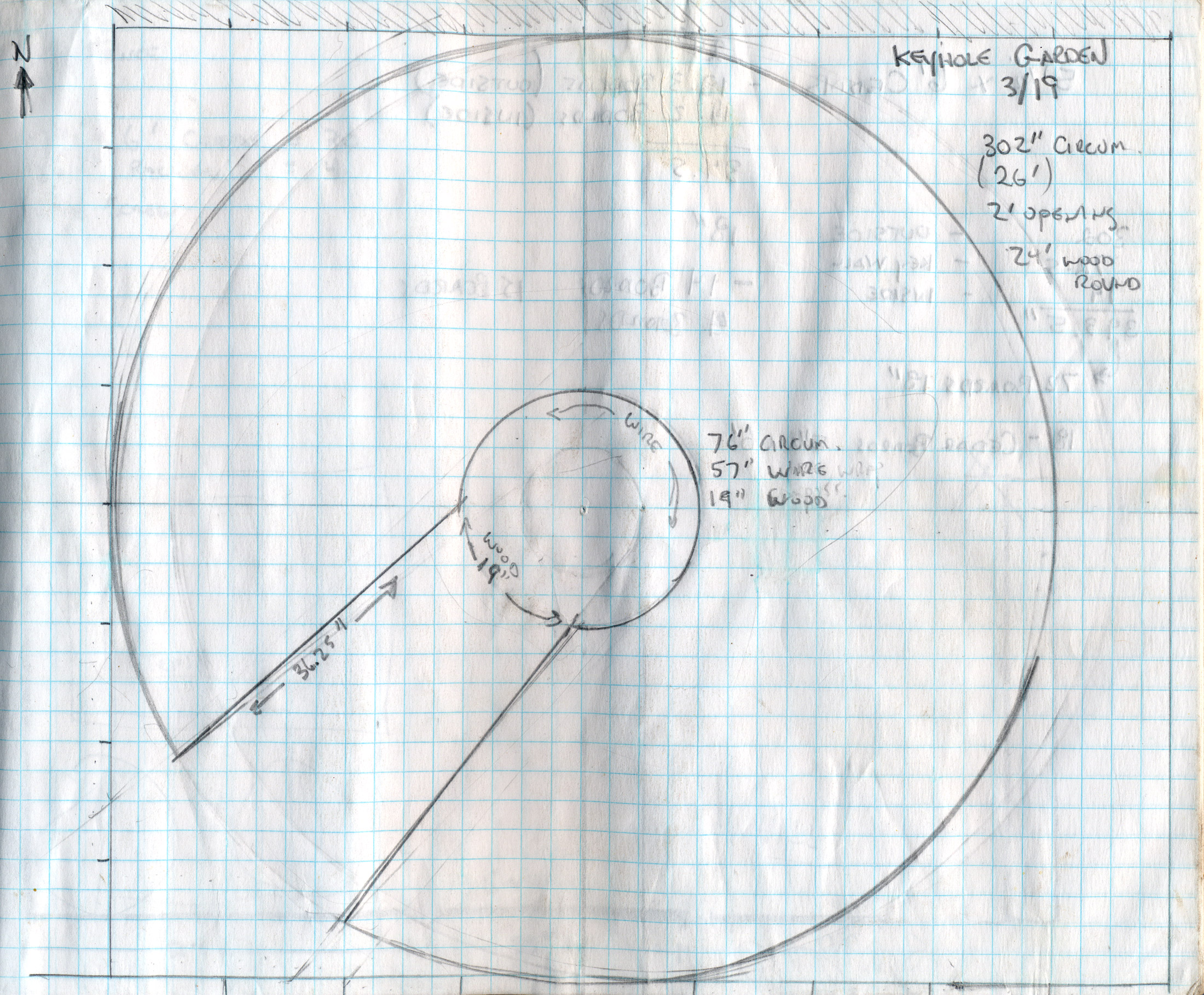
Most of the keyhole garden builds I read used a circular bed about 6 feet in diameter and 2 feet deep with walls made from stones, cinder blocks, bricks, and similar sturdy stuff. The area I wanted to build mine was the old kitchen garden, a 10 ft x 10 ft south-facing patch right outside the door. Not wanting to waste space, I decided to make my garden 8 feet wide with a two foot keyhole opening. I also made the compost basket in the center slightly larger to compensate for the additional planting area.
Because I wasn’t certain this whole keyhole garden thing was going to work out, I decided to skip the cost and effort of dragging (and possibly removing) a ton of stones or blocks to the area and go with a wood wall built like an open top barrel. I chose cedar fence boards as the wood because it was inexpensive, bugs didn’t like it, and held up well in the weather. I used standard 6 in x 6 ft dog-eared fence boards rather than 8 in x 6 ft because the narrower boards were less likely to split. For the “barrel bands” I chose ½-in stainless steel pipe strapping because it was (again) inexpensive and held up well in the weather.
My supplies list:
5½-in x 6ft Dog-eared cedar fence boards
Roll of stainless pipe strap
⅝-in screws
¼-in x 2 ft wire cloth (for the compost basket)
All of these things are available at any local hardware or home improvement store.
Step 2
Calculate How Much You Need
Thank a geometry teacher if you can read this
With a supplies list in-hand, the next thing I had to do was to calculate how many cedar boards and screws I was going to need. I planned on cutting the cedar to 18 in, giving me 4 boards for each piece of fencing. Each cut board would need 4 screws to attach it high and low to two bands of pipe strapping. So figuring out the circumference of the bed would tell me the number of cut boards and screws I need.
Except… the bed also has a “wedge” cut out of it that’s 2 ft wide at the edge and 18 in wide in the center where it meets the compost basket. Those extra three pieces (left, right and center) actually make the number of boards required higher that just the circumference.
Calculating the circumference of the bed was easy enough:
C=2Πr
Or, for my purposes the Circumference = 2 x 3.14 x 4, which just a tad over 25 ft. Subtract 2 ft from that for the opening to the keyhole, and you’ve got 23 ft and change for the outer wall. (Mr. Janko, if you’re reading this, I owe you a huge apology. Despite my earlier statements to the contrary, I did actually end up using geometry for something.)
Figuring out the amount of wood I’d need for the walls of the keyhole was more complicated. I had to determine the base angles of the isosceles triangle that was the “wedge” formed by the keyhole, then determine the intersection of the compost bin and the wedge, and calculate the length of the walls from there.
When that didn’t work, I used a tape measure and eyeballed it.
You should too. It’ll save you a whole bunch of time and some negative consequences that come from calling and threatening your high school geometry teacher in the middle of the night.
Anyway, all told, I needed a minimum of 16 uncut cedar boards, and 18 if I wanted to leave room for splits, cracks, bad measurements and all the other stuff that can happen. I bought 20.
Between the wood, screws and 100 ft of pipe strap, I spent about $100.
Step 3
Cut your boards to size
Cut the cedar boards to 18 inches long
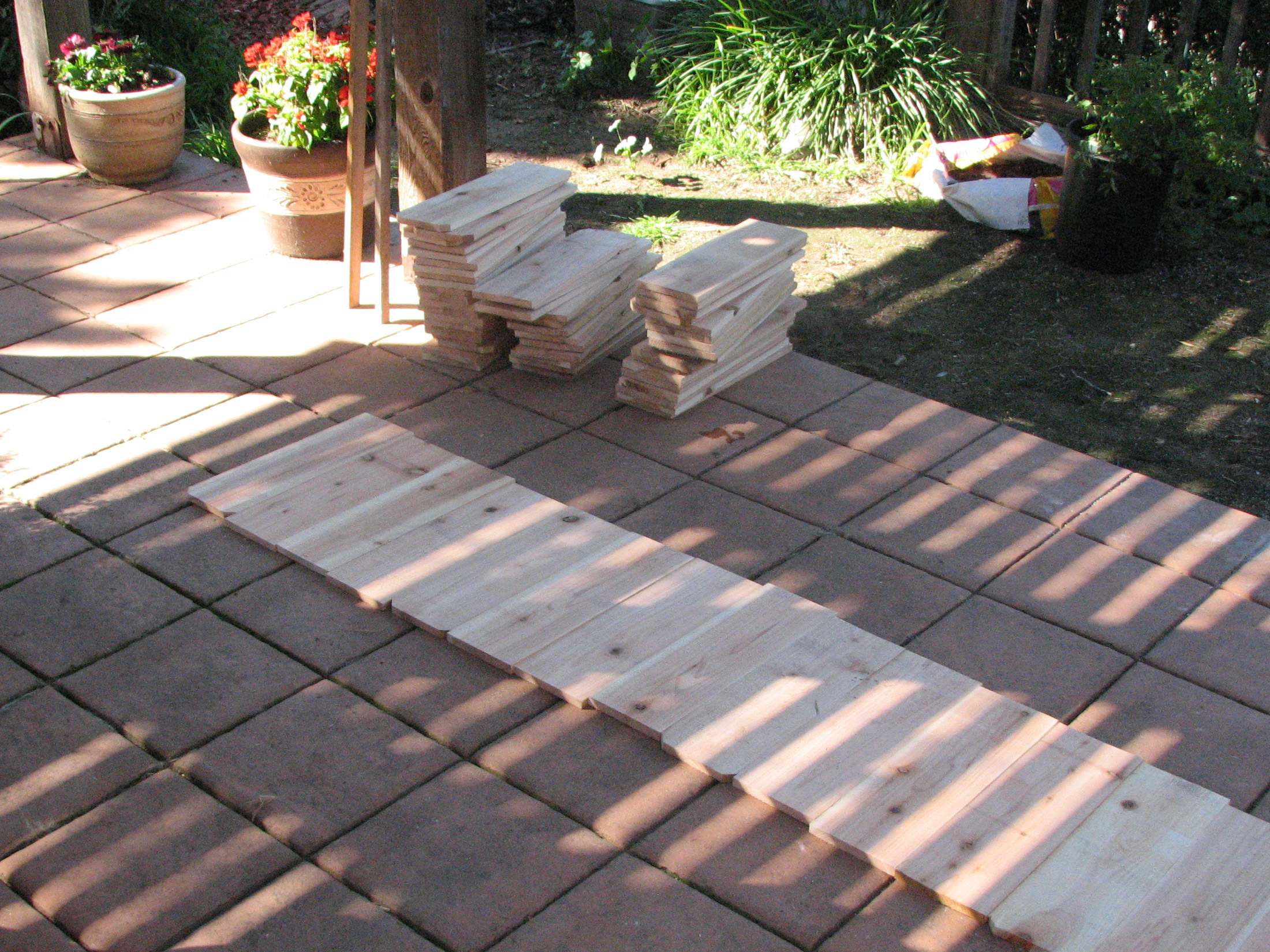
I decided to make my keyhole garden 18in instead of 24 in high because there’s a nice view out the dining room window and I didn’t want the garden wall to block half of it. Plus, dropping the size 8 in let me get 4 pieces per fence board rather than 3.
Somewhere between 20 and 350 cuts later, I had my stack of wall pieces.
Step 4
Building the main wall
Line up the boards and cut a length of pipe strap
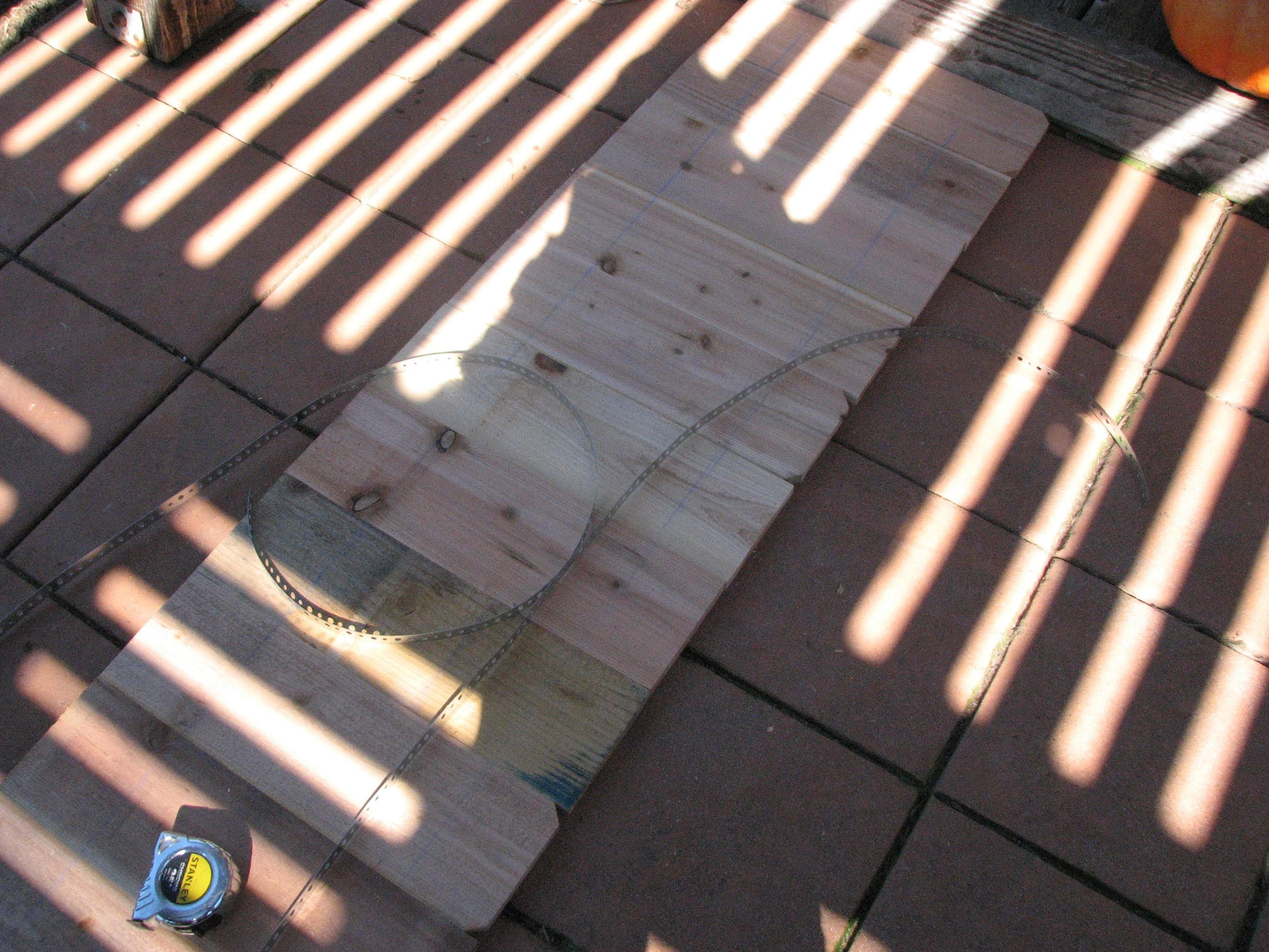
The first thing I did was build the main portion of the keyhole garden’s wall — the whole circle except for where the 2 ft keyhole opening would be. For my project that was 51 pieces of 18 in cedar boards (total length divided by the width of each board).
To put the wall together, I laid the boards down side-by-side, evened them up with a 6 ft level, and screwed two sets of pipe strap, one at 6 in from the top edge and another 6in from the bottom. Two screws per strap, four total on each board. When I got to the last board, I extended the the pipe stripe 12 in more and cut it. That piece would be used to join it to the interior wall of the keyhole.
Attach the pipe strap to the boards with 5/8 in screws
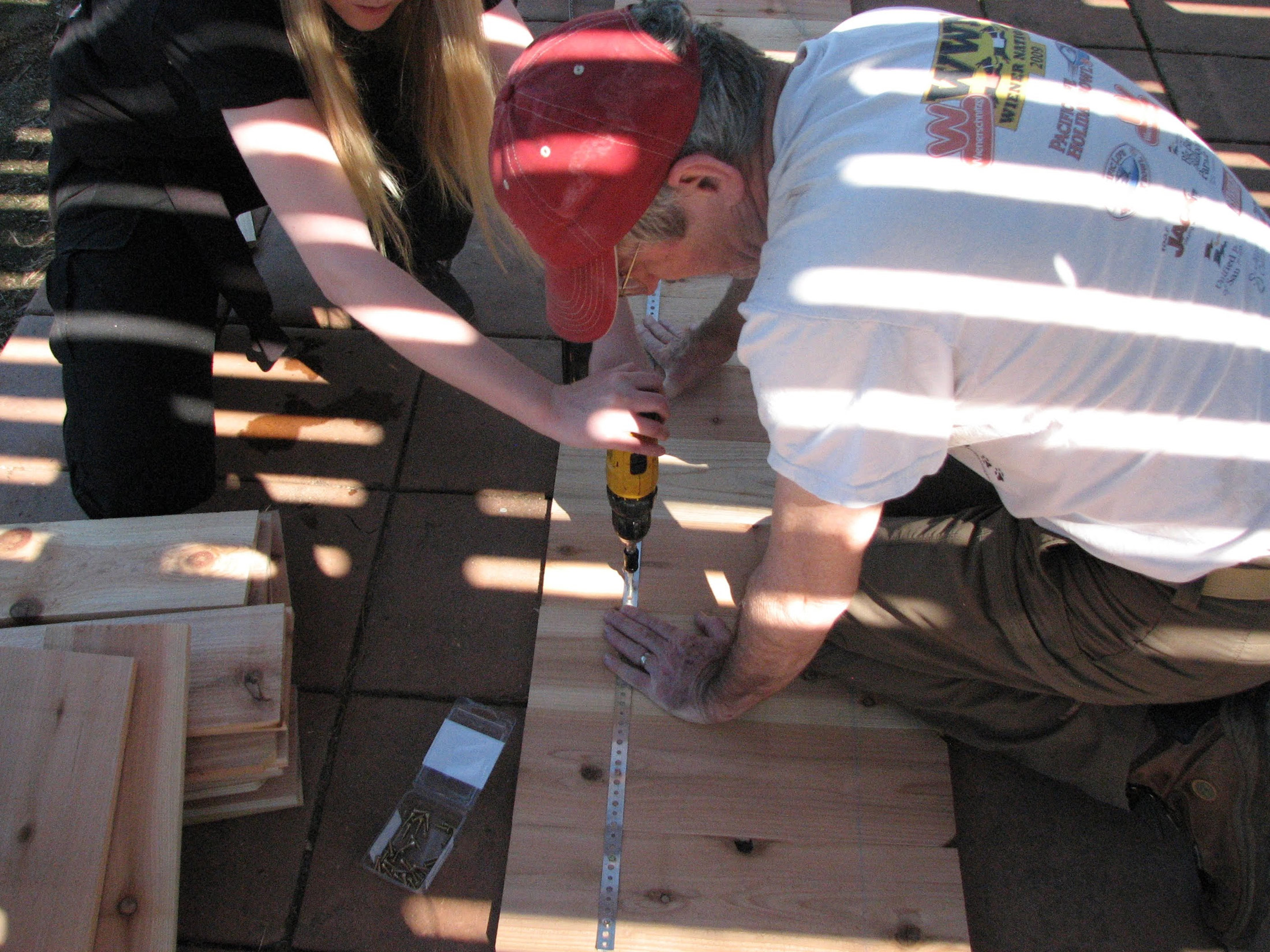
Finally, with the assistance of a helper, we brought the long “snake” of joined boards and stood it up in the garden. We knew where to place the wall because we had used a couple of stakes and a 4 ft length of twine to mark the circle’s boundary.
Stand up the assembled wall in the garden
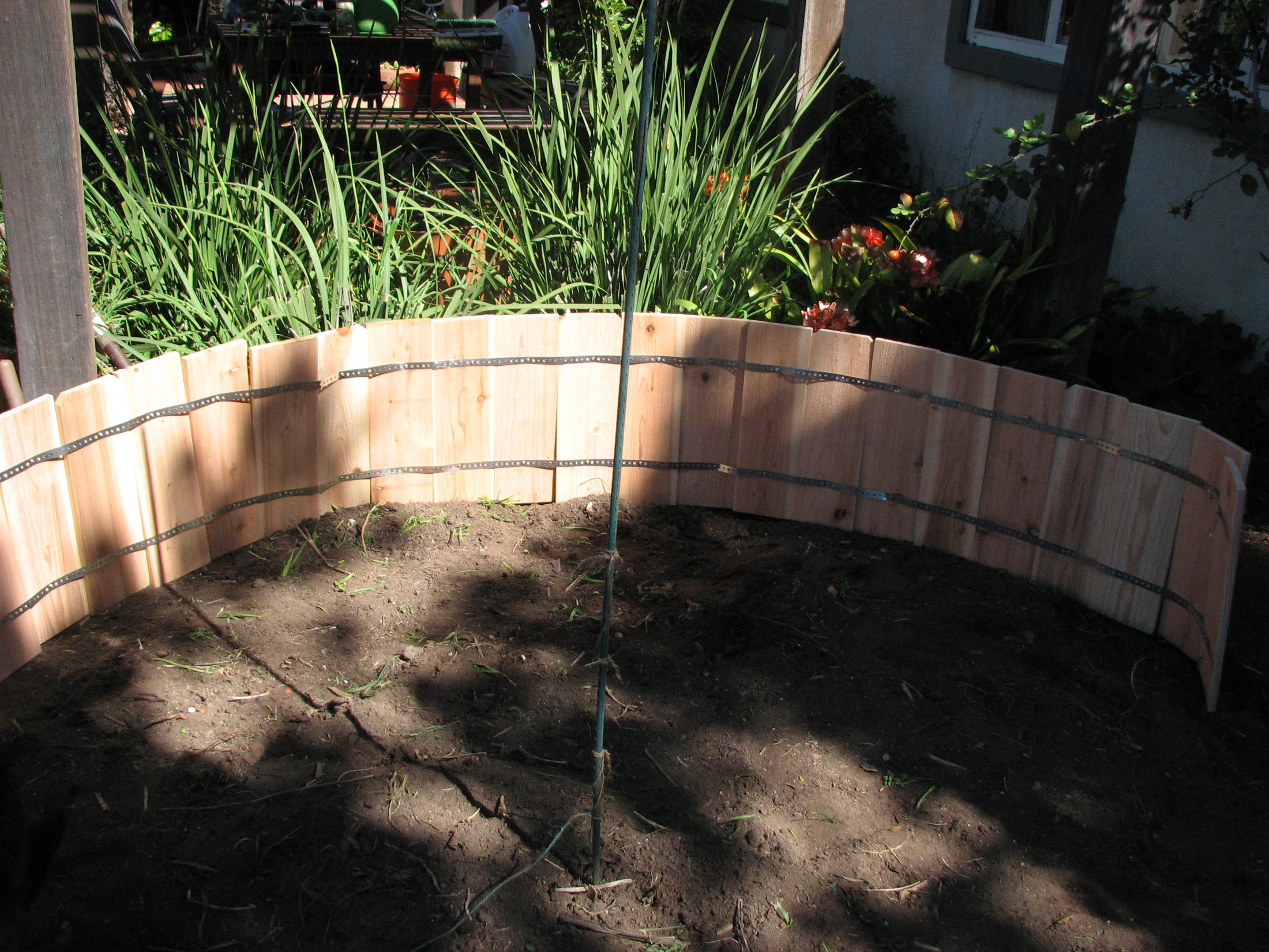
Step 5
Assemble the keyhole walls
Once the main wall was in place, we used the same double strap technique to assemble the right and left walls of the keyhole along with the center section where the compost basket would sit.
Then we stood those up and screwed them to the main wall using the extra 12 in of strap to join the pieces.
Step 6
Make the compost basket
Assemble the compost basket with a length of weld wire cloth
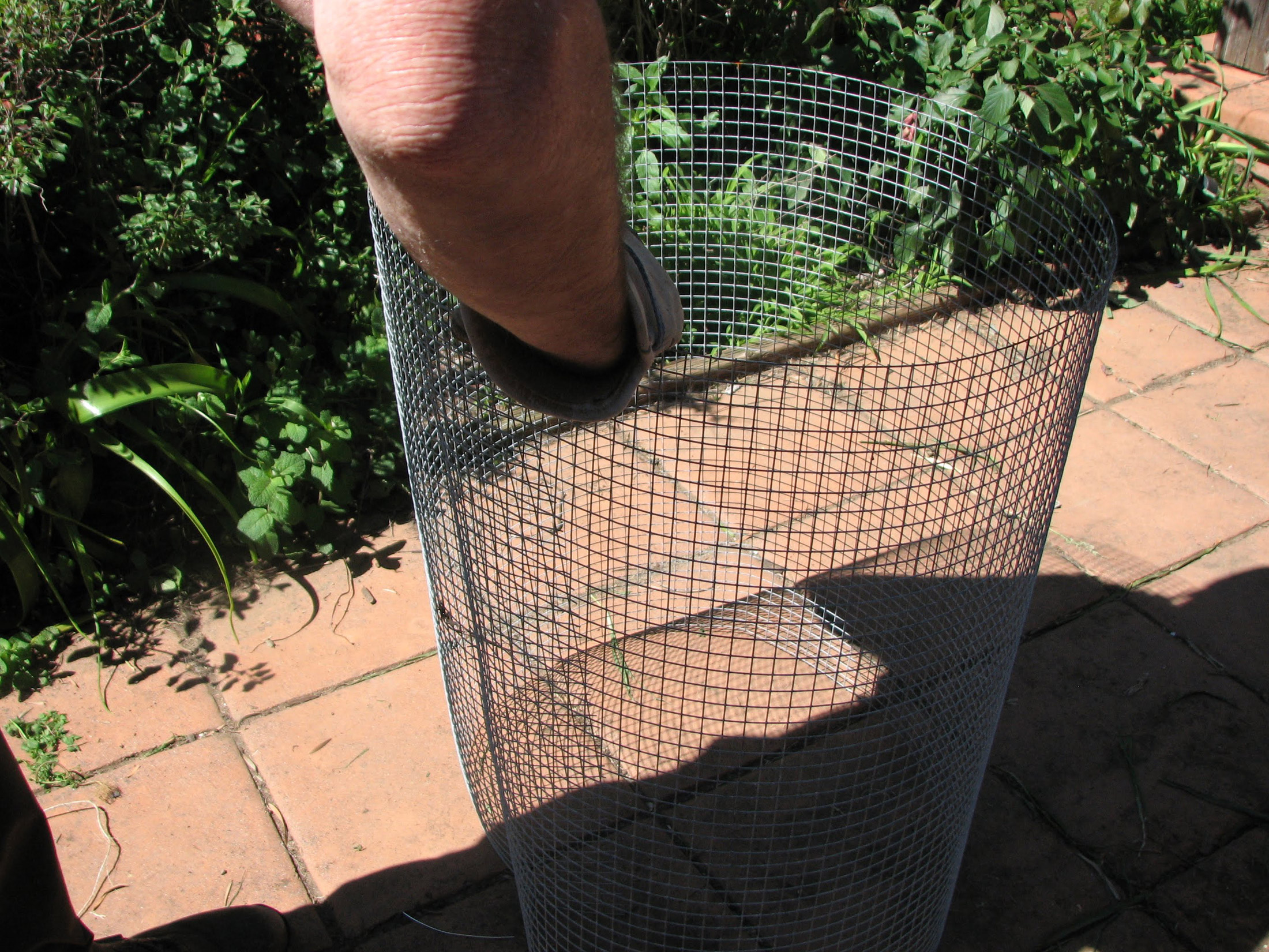
To make my compost basket, I unrolled a few feet of weld wire, shaped it into a tube 3 ft across and used some wire to tie the ends. Then I dropped it in place in the center of the garden and secured it with two garden stakes to keep it from collapsing when we filled the soil in around it.
Place the compost basket in the center of the garden bed to complete the keyhole
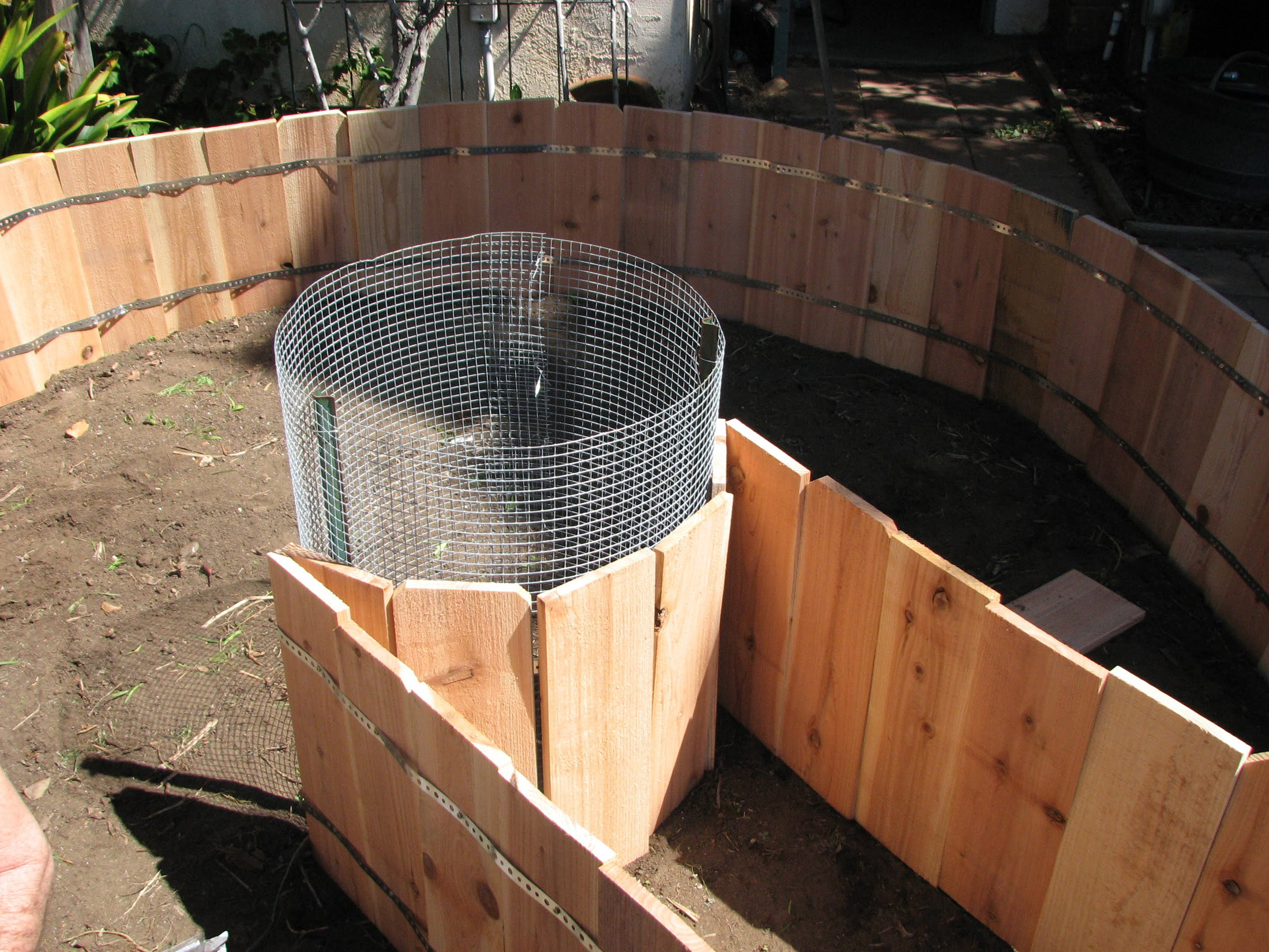
With that complete, it was time to fill the bed.
Step 7
Add debris to the bottom of the bed
A 6 in layer of twigs, leaves and sticks
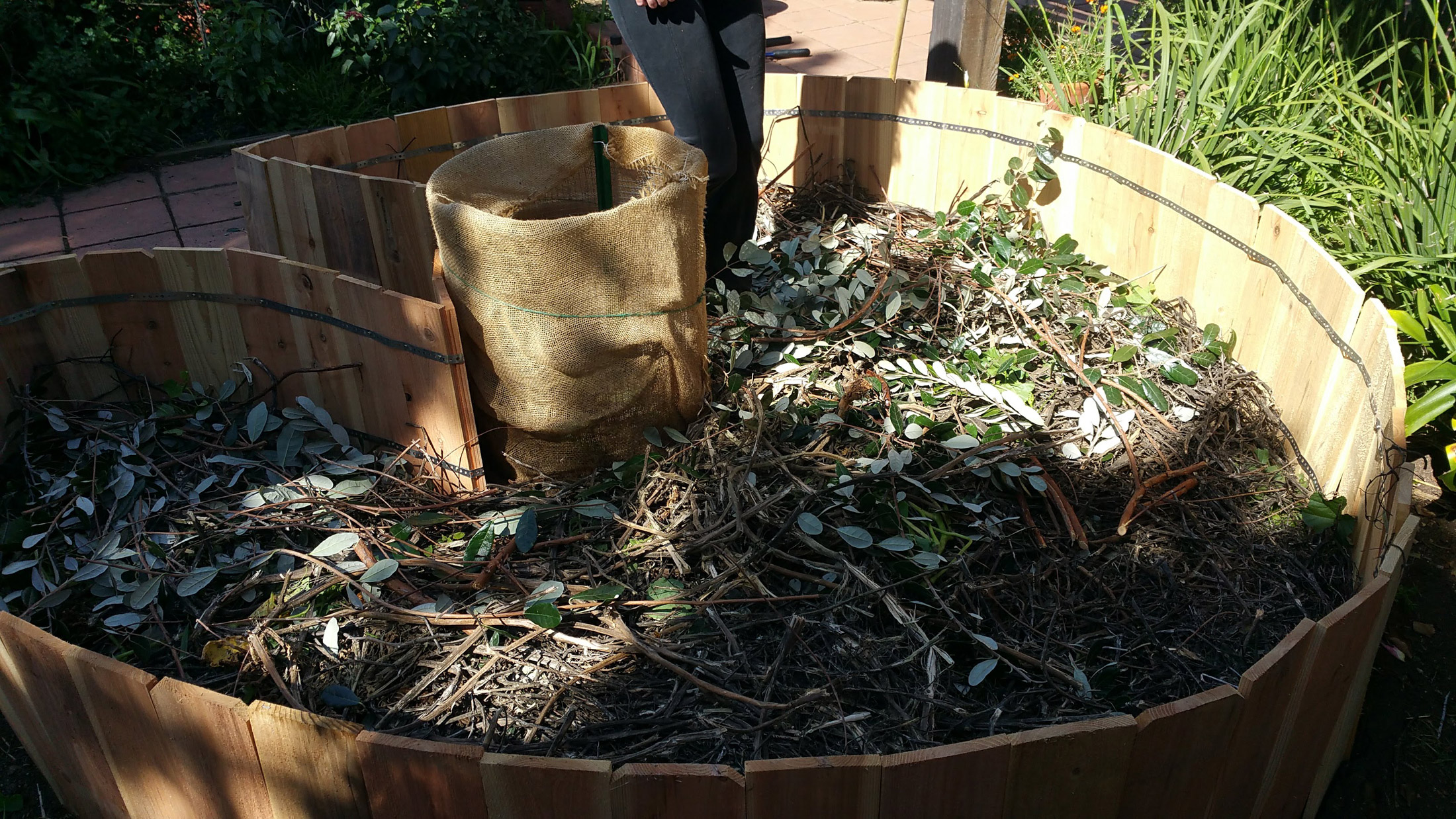
The bottom portion of the keyhole garden is a layer of course plant matter and compostable materials — branches, twigs, leaves, even bark and cardboard — to provide drainage and organic matter. Fortunately, I had plenty of that, so the bed was lined with feijoa branches and leaves, spent grapevines and tomato vines left over from fall. After adding and smashing it down we had about 6 in of coarse organic matter.
Step 8
Add Soil to fill the bed
Adding soil and manure to the bed
Next step was to figure out how much soil it would to take to fill the bed. (If you already have plenty of soil, skip this and simply fill the bed.) To do that, I had to know the radius of my bed (4 ft), and how high the soil would be when the bed was full (1-½ft). Then using my high school math again, I calculated the volume of the bed like this:
Volume=Πr2h
(You can also just and plug it in to the Google.)
Once I knew how much soil I needed, I checked prices at both the local home improvement stores and landscape centers, but didn’t find much difference. I chose the home improvement store because their 1 cubic foot bags were easier to carry to the garden than navigating the paths with wheelbarrows of loose dirt. I spent about $100 on the soil.
Add your soil to the bed. (That’s me. King of dirt mountain)
After I got the soil, I filled the beds and mounded it to slope away from the compost basket and help nutrients and water to leech from the compost to the outer edges of the bed. Finally, I gave it a good watering and let it sit for a couple days so air pockets between the soil and debris would settle so I didn’t wind up with “sink holes” later in the season.
Step 9
Plant Something!
The keyhole garden complete and ready for planting
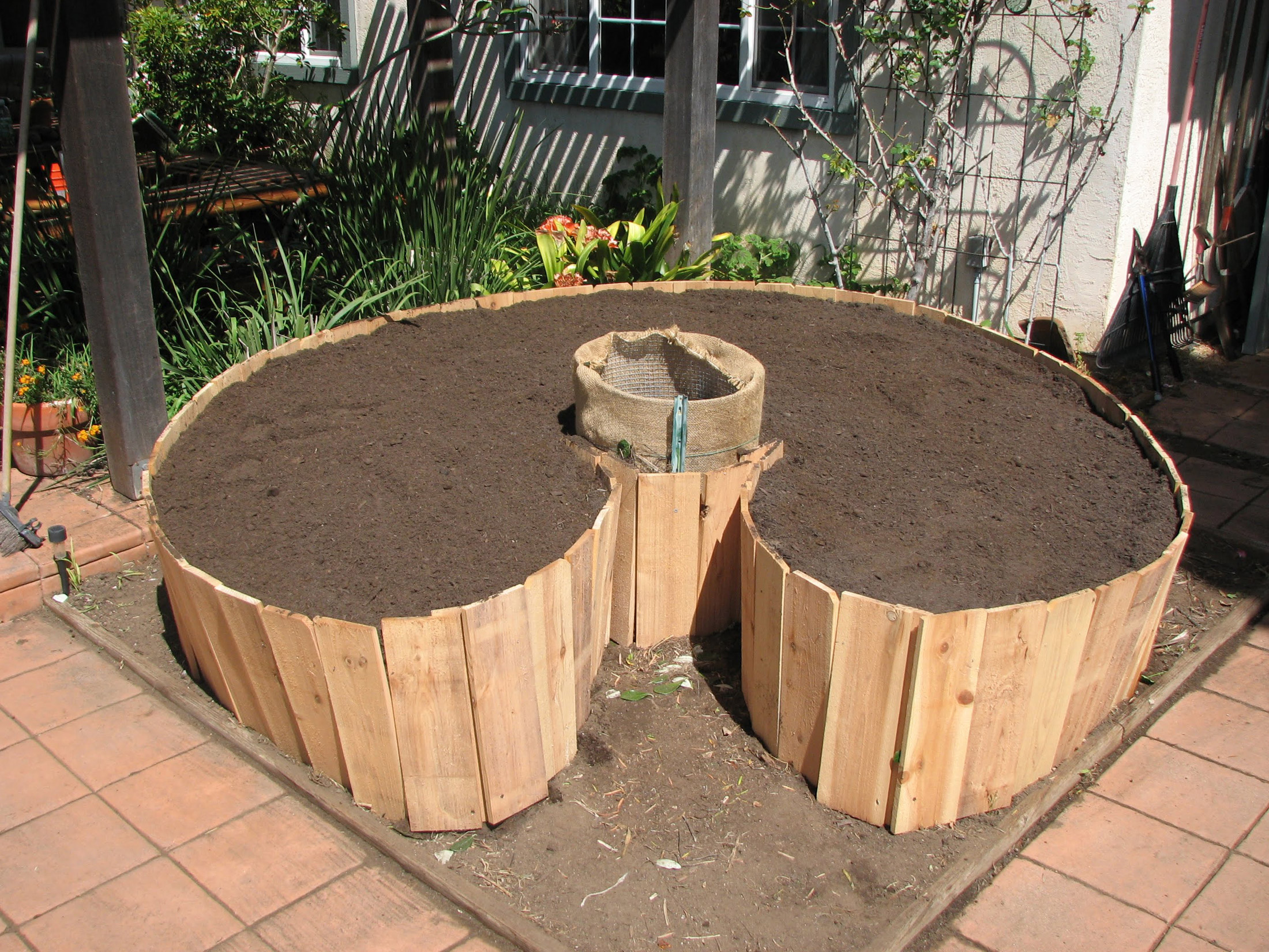
At this point the garden was good to go, so I started moving seedlings out of the greenhouse and into the bed. Here’s what I planted over the course of the growing season:
April
Broccoli (Arcadia)
Cucumber (Boston Pickling)
Lettuce (Loose leaf mix)
Tomato (Tigerella and Valentine)
Zucchini (8 Ball)
May
Basil (Genovese)
Carrot (Napoli)
Onion (Gladstone)
June
Frying Pepper (Corno)
Hot Pepper (Red Ember)
July
Basil (Large Leaf)
Corn (Red Dent)
Pumpkin (Rouge Vif D’Etempes)
Some of the articles I read about keyhole gardens mentioned that wide spreading, shallow root vegetables tomato and zucchini wouldn’t perform as well as other crops, but my results didn’t match that. The tomatoes eventually took over half the bed and the zucchini produced so much fruit that the ducks and chickens ended up getting plenty as well (yes, they love squash).
I also had to wrestle with sweet potatoes I apparently missed when we cleared the area to build the keyhole garden. They didn’t grow in the bed, but sprouted from the bottom and took off from there, eventually creeping over the top and swallowing the compost bin (which I still used).
Summary
Yes, it’s a great garden design
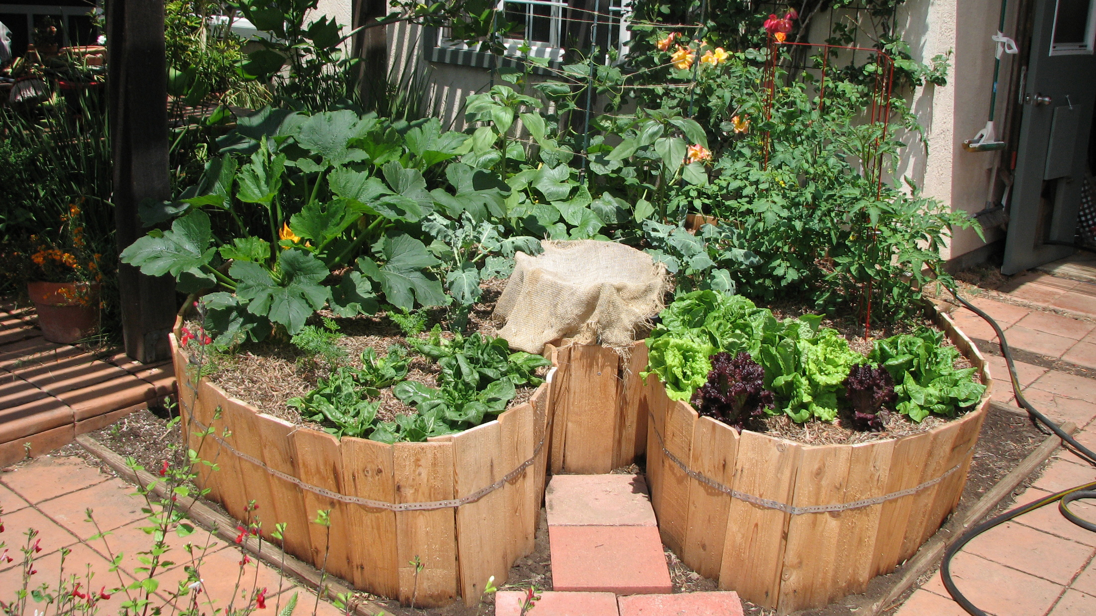
All told the yield from the keyhole garden was easily twice that of the standard raised beds down in the vegetable garden, and watering and upkeep was far easier. I did have some problems early with the soil drying too quickly (we only get rain between November and March), so I laid down a soaker hose and placed about 3 in of leaf mulch over it to control evaporation.
After that it was basically zero care and continuous production from May through September. Definitely worth the $200 and the few hours I put into building it. If you build one, I have no doubt you’ll be equally pleased at how much food production you’ll get out of such a small area.
If you’d like to see the keyhole garden throughout the year, check out this post.
La proposta progettuale nasce e si sviluppa da valutazioni riguardanti il complesso sistema degli accessi all’area, dei percorsi pedonali e viabilistici, dalla ricerca di una corretta integrazione dell’edificio con il masterplan dell’intera zona e, non ultimo, dalla sensibilità nei confronti dei fattori climatici del contesto.
Il corpo di fabbrica è articolato in due ali, dalle forme organiche efficientemente interconnesse ed atte ad accogliere luce e verde al loro interno. La “cellula” del palazzo ad uffici si apre verso sud per dare accesso ai sistemi di circolazione pedonale legati al programma del masterplan, favorendo la compenetrazione tra edificio ed un ricco sistema a verde in continuità con il tessuto del progetto dell’intero complesso. Il piano terra, prevalentemente vetrato, minimizza l’attacco a terra del nastro di facciata ed accentua la permeabilità dell’intervento al livello degli attraversamenti pedonali favorendo il dialogo simbolico tra l’area a verde naturale situata nella zona a nord del masterplan con le aree verdi più “urbane” della zona centrale. Il locale bar presente nell’ala ovest aumenta ulteriormente l’integrazione dell’edificio con le attività e le relazioni in atto nell’intero complesso di progetto. Oltre che dal locale bar, l’accesso all’edificio avviene tramite un atrio passante posto nel punto di connessione tra le due ali nel quale si affacciano sia l’ingresso pedonale, sia l’ingresso da una zona di drop-off.
La facciata è concepita come una superficie continua, un nastro tecnologico che si sviluppa adattandosi alle diverse condizioni al contorno: la pelle dell’edificio si adatta e legge, in modo efficiente, l’incidenza del sole nelle diverse stagioni, nella costante ricerca di una efficienza ed ottimizzazione energetica. Pensato perciò come un grande filtro di luce dell’edificio, proprio per questa capacità intrinseca di adattarsi al contesto, genera ambienti nei quali è garantita un’elevata qualità abitativa in termini di comfort climatico ed illuminotecnico.
Costituzione e funzionalità dell’edificio:
L’edificio può essere considerato costituito da due ali connesse tra loro:
- l’ala est costituita da otto livelli fuori terra a destinazione uffici, un livello interrato a parcheggio e un livello “giardino” in copertura;
- l’ala ovest costituita da sette livelli fuori terra di cui sei destinati ad uffici e uno ad uso bar-ristoro al piano rialzato; completano quest’ala un piano tecnico per gli impianti in copertura e due livelli di parcheggi di cui uno seminterrato e uno interrato.
L’altezza complessiva dell’edificio è pari a 33,50 m sul fronte ovest e 30,00 m sul fronte est, mentre l’altezza utile ai fini urbanistici, misurata all’intradosso della soletta dell’ultimo piano abitabile, è di 29,35 m inferiore a quella prevista dalla sagoma limite del piano particolareggiato (29,60 m).
I livelli dell’edificio presentano un interpiano di 370 cm da pavimento finito a pavimento finito e un’altezza interna netta di 280 cm con pacchetti di soletta pari a 90 cm comprensivi di controsoffitto e pavimento galleggiante.
L’edificio sviluppa una superficie lorda di pavimento totale pari a 9.723 mq di cui 327 mq sono destinati all’area bar ed il resto ad uffici e servizi.
La conformazione tipologica-planimetrica dell’edificio permette l’insediamento di diverse tipologie aziendali consentendone l’utilizzo da parte di un unico locatario, di due locatari (mediante la suddivisione della pianta in due corpi di fabbrica autonomi e distinti) o infine di più locatari mediante la suddivisione su livelli (di 1329 mq di Slp) o semi-livelli (di 663 mq e 760 mq rispettivamente).
L’ipotesi della soluzione per bilocatario ha suggerito la possibilità di una completa divisione funzionale dell’edificio a partire dall’atrio che è studiato per poter essere frazionato in due parti con accessi distinti ed autonomi.
I blocchi servizi:
Lo schema distributivo dei piani presenta due blocchi servizi, uno per ogni ala. Ognuno di questi blocchi, contiene due vani scala, ciascuno con filtro a prova di fumo, comprendenti due ascensori di portata 12 persone / 900kg (cabina 140x150 cm, porte 90 cm) e un montacarichi di portata 13 persone / 1000.kg (cabina 100x210 cm, porte 90 cm).
Scale e ascensori sono collegati all’atrio, ai due piani di parcheggi interrati e al piano di copertura.
Tre delle quattro scale dell’edificio risultano attigue alle facciate e sono pertanto rese aperte e considerate “scale fredde”; ai fini urbanistici tali scale non rientrano nel calcolo della superficie lorda di pavimento. La quarta scala, in posizione non adiacente alla facciata, viene considerata, come previsto dal regolamento d’igiene, “scala primaria” e perciò chiusa, pur mantenendo le adeguate aperture per l’areazione naturale alla base ed in sommità come previsto dallo stesso regolamento.
Il dimensionamento ed il numero delle scale è conforme a quanto previsto alla normativa antincendio, mentre quantità e capacità degli ascensori sono misurate ai flussi di persone previsti nell’edificio che nell’ipotesi di massimo affollamento vengono stimati su una quantità di circa 900 persone.
In ognuno dei blocchi servizi sono presenti anche i servizi igienici divisi per sesso (2 per uomini, 2 per donne) più un servizio per disabile, un locale pulizie, un locale quadro elettrico, un locale dati/fonia (con rispettivi cavedi di passaggio delle reti) e un grande cavedio per le principali distribuzioni impiantistiche.
L’area uffici:
Le restanti parti del piano, che comprendono tutti gli affacci esterni dell’edificio, presentano pianta libera consentendo una notevole flessibilità di distribuzione e permettendo di creare zone open-space alternate ad uffici singoli, doppi o quadrupli in un numero molto elevato di soluzioni in grado di offrire ampio margine alle esigenze dei futuri utenti.
Il nastro continuo di facciata, assieme al passo della maglia strutturale, si relaziona con gli ambienti interni diventando il principio ordinatore capace di generare e modulare le diverse configurazioni di distribuzione interna garantendo in ognuna di esse eccellenti condizioni climatiche e di illuminamento. Il contatto con il mondo esterno e la qualità abitativa in termini di confort climatico ed illuminotecnico interno, unite alla possibilità di personalizzare le condizioni ambientali attraverso l’apertura delle finestre, sono state ricercate ai fini dell’ottenimento delle migliori condizioni di comfort psico-fisico per gli utenti.
In entrambe le ali dell’edificio la maglia strutturale presenta un modulo base di 5,70 m ed è studiata per permettere la formazione sia di locali per uffici dirigenziali o locali per uffici quadrupli di larghezza netta interna di 5,50 m, sia locali per uffici singoli di larghezza interna netta 2,70 m. La profondità di tali locali è variabile dai 5,50 m ai 6,50 m a seconda della posizione nella pianta.
Nella soluzione open-space si ha invece la possibilità di posizionamento di 3 gruppi di 6 tavoli operativi (di dimensioni 160 x 80 cm) ogni due campate strutturali. In questa soluzione, che risulta quella che determina il maggior affollamento dell’edificio, si possono contare un numero pari a 130 postazioni per ogni piano, quantità compatibile con il massimo affollamento previsto dalla normativa antincendio (132) in relazione alla larghezza delle vie d’uscita.
I percorsi di distribuzione interna orizzontale nei piani, di larghezza minima 150 cm, si svolgono in modo lineare lungo i corpi servizi, comprendendo anche gli sbarchi degli ascensori e le loro lunghezze sono commisurate alle massime distanze consentite per le vie di fuga.
Il posizionamento ed il numero delle finestre apribili, con apertura verso l’interno ad anta semplice a tutta altezza, è studiato in modo tale da garantire almeno un’apertura per ogni modulo base di 5,70 m, senza interferire con la posizione dei pilastri strutturali. Inoltre ad ogni piano, in alcune zone della pianta, sono previste due aperture per modulo base per permettere la formazione di uffici singoli di larghezza 2,70 m areati e illuminati autonomamente. Il numero e il posizionamento delle finestre apribili determina per ogni piano la massima suddivisibilità in uffici chiusi e di conseguenza la quantità e il posizionamento delle dotazioni impiantistiche necessarie per ogni livello.
I rapporti aero-illuminanti risultano soddisfatti negli uffici singoli considerando unicamente le finestre ad anta apribile mentre per gli uffici doppi o per le aree open-space sono da aggiungere ai fini del calcolo del rapporto illuminante anche i contributi dovuti alle specchiature non apribili considerando le percentuali di illuminamento determinate dalla presenza delle lamelle di legno all’interno delle vetrocamere (variabili dal 45% all’80%).
La flessibilità distributiva interna è inoltre rafforzata dall’impiego di pavimenti sopraelevati per facilitare l’accessibilità alle reti e controsoffitti ispezionabili modulari con le soluzioni di layout sopra elencate.
Nella zona di connessione tra le due ali, dove il corpo di fabbrica è più profondo, possono trovare spazio sale riunioni, locali per archivi e spazi relax. Questi ultimi si affacciano verso il fronte interno, più privato, della corte attraverso delle terrazze che via via si fanno sempre più aggettanti salendo in altezza nell’edificio e che fungono anche da protezione solare per la facciata interna esposta a sud. In corrispondenza del punto di massimo aggetto dei terrazzi sono previsti tiranti strutturali in acciaio inclinati a sostegno degli sbalzi.
Su questo fronte terrazzi e specchiature trasparenti accentuano la profondità nella corte dell’edificio.
Il basamento:
Il basamento dell’edificio è costituito da un livello uffici nell’ala est, direttamente confinante con area verde esterna, dall’atrio d’ingresso a doppia altezza e dall’area bar-ristoro, rialzata rispetto alla quota zero della strada di 2,00 m, venendosi a trovare sopra il primo livello, seminterrato, dei parcheggi.
Gli accessi all’edificio avvengono tramite l’atrio passante posto nel punto di connessione tra le due ali sul quale si attestano sia l’ingresso pedonale interno alla corte, sia l’ingresso da nord dalla zona di drop-off. Su entrambi i fronti dell’atrio sono previste bussole d’ingresso vetrate con doppia porta, direttamente affacciate sulla doppia altezza interna dell’atrio pari a 6,30 m. La bussola verso sud viene a crearsi dal prolungamento e la piegatura delle stesse superfici del basamento, in continuità con il disegno del percorso pedonale di accesso. Quella verso nord permette inoltre l’accesso controllato alla rampa pedonale interna che porta all’area bar. La conformazione dell’atrio e delle stesse bussole consente la possibilità di suddivisione dello spazio dell’atrio in due atrii separati nell’eventualità di suddivisione verticale dell’edificio per la soluzione del bilocatario.
Adiacente alla bussola nord e al bancone della reception è previsto un piccolo locale back-office utilizzabile per l’inserimento degli apparati telefonici ed eventualmente accessibile dalla stessa bussola.
Nell’ala ovest del basamento trova posto il bar servito da un bancone e un’area cucina con spogliatoio e servizi igienici per il personale dipendente. L’altezza interna netta dell’area bar è di 4,50 m. E’ presente inoltre un piccolo montacarichi per merci che mette in comunicazione la cucina con il primo livello interrato sottostante.
La punta sud dell’area bar, protendendosi verso l’area verde e gli spazi pavimentati esterni si svuota e lascia posto ad uno spazio coperto caratterizzato dalla presenza di pilastri inclinati che penetrano nella soletta in calcestruzzo a vista opportunamente sagomata per ricevere un inspessimento della parte strutturale e consentire una distribuzione dei carichi che provengono dai piani superiori. La connotazione architettonica di questo spazio caratterizza fortemente il luogo di percorso e sosta, crocevia di alcuni percorsi esterni di interconnessione tra le zone del contesto adiacente e la corte dell’edificio che passano per la terrazza del bar adibita a spazio per il pranzo all’aperto.
Il disegno della soletta, “svasata” lungo il perimetro di questa parte di edificio, si protende all’interno del bar e lungo la rampa interna fino a raggiungere la bussola d’ingresso mettendo concettualmente e visivamente in comunicazione questi spazi.
La copertura:
Il livello della copertura dell’edificio ospita una zona destinata agli impianti in corrispondenza dell’ala ovest ed uno spazio comune all’aperto sull’ala est da utilizzare come “tetto giardino”, luogo di rappresentanza dell’edificio, destinato alla sosta e lo svago potendo godere di una vista panoramica a 360° sull’intorno del progetto.
La zona impianti, racchiusa perimetralmente dalla stessa “pelle” di facciata che la rende parte integrante della composizione dell’edificio, contiene i gruppi frigoriferi, le unità di trattamento aria, gli estrattori, le pompe e l’impiantistica elettrica. Questi ultimi due impianti, così come i vani scale e ascensori che raggiungono il piano copertura, saranno coperti da una soletta mentre la restante parte sarà coperta da un grigliato frangisole di metallo che si protende anche nella zona accessibile agli utenti per creare spazi d’ombra all’aperto. Le parti non grigliate della copertura ospiteranno pannelli solari e pannelli fotovoltaici a servizio dell’edificio.
Lo spazio a tetto-giardino, pavimentato in doghe di legno, è racchiuso da un parapetto in vetro arretrato dal filo della facciata per non essere visibile dal livello del parco e contornato da un “giardino” di pietre, non praticabile, pensato in modo tale da non necessitare di manutenzione.
Sono previsti inoltre due locali deposito coperti a servizio degli spazi di copertura, accessibili dalle aree comuni praticabili.
L’allontanamento delle acque meteoriche in copertura avverrà mediante la formazione di piani con opportune pendenze e una canalizzazione centrale con pluviali collocati all’interno dei cavedi già previsti.
I parcheggi:
Sotto l’edificio sono stati collocati i parcheggi pertinenziali su due livelli di cui uno seminterrato a quota –1,40 m rispetto alla strada ed uno interrato a quota –4,60 m.
Il primo livello interrato presenta una superficie di 1297 mq con 21 posti auto e 46 posti moto, il secondo livello ha invece una superficie di 2242 mq con 55 posti auto e 23 posti moto, per un totale di 3539 mq che rispetta abbondantemente il minimo previsto per legge (2.916 mq, Legge Tognoli).
L’altezza interna netta dei due livelli è di 2,70 m tale da consentire l’eventale passaggio di impianti a soffitto.
L’accesso ai parcheggi avviene dalla strada che costeggia l’edificio ad ovest e sarà reso possibile l’ingresso alle sole auto provenienti da sud impedendo la svolta e l’attraversamento di corsia per quelle provenienti da nord. Le rampe a doppia percorrenza hanno larghezza pari 6,50 m con pendenza media pari al 15%, mentre quelle singole hanno larghezza pari a 3,30 m. I due livelli di parcheggio costituiscono un unico compartimento e per normativa dovranno essere dotati di impianto automatico di spegnimento. Le areazioni necessarie sono adeguatamente dimensionate e uniformemente distribuite.
Al secondo livello interrato sono presenti inoltre locali impianti di altezza interna 4,00 m contenenti la centrale idrica, la centrale termica, il locale ups, la cabina di trasformazione, la cabina Enel accessibile da una botola sull’esterno e, fuori dalla sagoma dell’edificio, il locale per il gruppo elettrogeno anch’esso accessibile da una propria botola.
Un locale deposito rifiuti di circa 40 mq, sufficiente a soddisfare il fabbisogno dell’intero edificio, è collocato in corrispondenza della rampa di accesso al primo livello interrato ed è accessibile agevolmente dalla strada dai mezzi della nettezza urbana.
Le aree esterne:
Le aree esterne sono studiate per forme e materiali per una corretta integrazione delle linee di progetto con il disegno generale del masterplan ed in particolare con gli spazi verdi circostanti. La corte dell’edificio aperta verso sud accoglie gli accessi e i sistemi di circolazione pedonale favorendo la compenetrazione tra edificio e il sistema a verde in continuità con il tessuto del progetto dell’intero complesso.
Lungo tutto il perimetro dell’edificio è resa possibile la circolazione agevole di un mezzo per la pulizia e la manutenzione delle facciate garantendo una fascia percorribile di 3,50 m con possibilità, in alcuni punti, di inversione di marcia dell’automezzo.
Sul fronte strada la presenza del parcheggio seminterrato genera la formazione di un muro lungo il marciapiede pedonale fino all’area di drop-off. Tale muro conterrà parte delle areazioni dei due livelli interrati e sarà trattato come muro “a verde”.
Come per l’ingresso ai parcheggi l’accesso al drop-off sarà reso possibile ai soli veicoli provenienti da sud impedendo la svolta e l’attraversamento di corsia per quelle provenienti dalla rotonda a nord.
Le finiture interne:
Gli ambienti interni delle aree ad uffici avranno un aspetto “caldo” e accogliente con particolare cura per le aree comuni e gli sbarchi degli ascensori. I materiali saranno scelti tra quelli lignei e comunque in accordo con l’aspetto caratterizzante delle facciate dell’edificio.
Le aree operative sono studiate in modo tale da consentire un alto grado di flessibilità nella scelta di tipologia di partizioni e rivestimenti da parte dell’utente finale.
I controsoffitti in pannelli di lana di vetro ad alta densità con superficie visibile dell’aspetto dell’intonaco saranno tali da garantire alte prestazioni fonoassorbenti per evitare il riverbero del rumore all’interno degli ambienti e avranno una superficie continua complanare sostenuta da una struttura modulare non in vista che consente l’ispezionabilità degli impianti a soffitto.
Dotazioni impiantistiche e illuminotecniche sono studiate in accordo con la flessibilità e la modularità del layout della pianta. I corpi illuminanti a sospensione saranno di tipo ad emissione diretta ed indiretta e saranno orientabili grazie alla possibilità della loro rotazione a 90° per potersi adattare alle esigenze distributive interne.
L’atrio d’ingresso, luogo di filtro e di passaggio avrà un’immagine legata per aspetto e materiali all’ambiente esterno, in continuità visiva e materica con gli spazi pavimentati della corte. I materiali di finitura e rivestimento saranno della famiglia di quelli lapidei e riconducibili ad un linguaggio “urbano” e di spazio pubblico favorendo il dialogo simbolico con le aree verdi e quelle più urbane della zona centrale del masterplan generale. Stessa cosa per il locale bar.
La facciata:
Le facciate dell’edificio sviluppano una superficie complessiva di circa 5600 mq suddivisi in tre tipologie principali:
- la parte principale dell’involucro, tecnologicamente avanzata, che copre un’area complessiva di circa 3340 mq illustrata di seguito;
- la parte del basamento, continua, interamente vetrata composta da una semplice vetrocamera (superficie 784 mq circa);
- la parte all’interno della corte che affaccia a sud tramite i terrazzi aggettanti, anch’essa interamente vetrata composta da una semplice vetrocamera (superficie 161 mq circa);
- le zone di affaccio dei blocchi servizi prevalentemente cieche, composte da una parete in calcestruzzo armato finita esternamente con pannello in legno rivestito da una lastra in vetro (superficie 930 mq circa), inserite nello stesso disegno dei serramenti della parte principale ai fini di garantire una continuità visiva dell’intero nastro.
Il nastro tecnologico di facciata definisce l’identità dell’edificio dialogando con il contesto naturale e urbanizzato in cui è immerso ma allo stesso tempo assume altri importanti compiti. La “pelle bioclimatica” consiste in un sistema di facciata di tipo OKAWOOD, fornito dalla ditta OKALUX®, composto da una vetrocamera nella quale sono inserite lamelle in legno di essenza ontano di spessore 11 mm a passo variabile (20 mm, 40 mm, 60 mm). Il peso dell’elemento finito è riconducibile a quello di una comune vetrocamera (circa 40 kg/mq) mentre lo spessore del pacchetto è di circa 40mm.
I serramenti dell’elemento OKAWOOD sono previsti in acciaio inox spazzolato sia per ottenere una continuità formale con la struttura portante della facciata stessa sia per consentire la realizzazione di profili più sottili soprattutto nelle zone a curvatura più stretta dove un telaio in alluminio, confrontandosi con moduli di larghezza pari a 95 o 47,5 cm diverrebbe dominante rispetto alle superfici vetrate. L’utilizzo di questa tipologia di infisso determina, al fine di evitare problemi di condensa interna, l’integrale carterizzazione del serramento verso l’interno; la soluzione prevede quindi l’accoppiamento all’acciaio di profili in legno che contribuiscono a dare un’immagine più calda agli ambienti di lavoro. Lo studio delle tessiture dell’elemento frangisole si sviluppa adattandosi alle diverse condizioni al contorno assecondando diversi parametri come l’angolo d’incidenza solare (nelle diverse stagioni), l’altezza delle parti di edificio nella corte interna che non ricevono luce diretta (sempre nelle diverse stagioni) ed il contributo spesso svantaggioso degli apporti solari. Il risultato consiste in una pelle che si adatta e si raffronta in modo efficiente con il tema della luce naturale evitando fenomeni di abbagliamento e con il tema del risparmio energetico ponderando gli apporti solari, nella costante ricerca di una efficienza ed ottimizzazione energetica ed illuminotecnica.
I serramenti che compongono l’involucro fanno parte di un abaco modulare in grado di soddisfare sia le esigenze compositive esterne sia le altrettanto importanti esigenze distributive interne rendendo di fatto la facciata il motivo ordinatore di una distribuzione flessibile ed efficiente degli spazi interni.
Nel nastro si alternano in modo non casuale, sia per la loro uniforme distribuzione che per l’integrazione con la struttura portante perimetrale, 242 serramenti apribili ad anta interamente trasparenti di un’unica dimensione pari a 95 x 320 cm (appartenente anch’essa all’abaco) per una superficie totale di 735 mq.
Lo studio modulare della facciata non si limita alla definizione dell’abaco precedentemente accennato ma anche alla possibilità di tagliare la facciata con una serie di giunti verticali continui scomponendo la pelle esterna in strisce sempre modulari (3M,4M,5M.....con M pari a 95cm) in stretta relazione con la fruibilità e la flessibilità interna degli spazi e garantendo una più agevole messa in opera. La larghezza delle strisce modulari varia a partire da 3M fino ad arrivare a 11M (con l'eccezione di 4 piccole strisce, formate da 3 mezzi moduli, di larghezza complessiva pari a 1,5M poste nei punti dove la pelle necessita di raggi di curvatura molto bassi). Individuate le misure e le rispettive quantità delle diverse strisce modulari è stato creato un abaco di soluzioni che permette di mantenere l’iniziale idea compositiva della facciata semplicemente affiancando e alternando i componenti del nuovo macro-abaco così creato.
Your political drawer...Your more liberal stuff on the far left and your ultra conservative gear buried in the right corner.
Joint Forces Training Base home to energy-efficient headquarters
LOS ALAMITOS, Calif. -- Soldiers, family members and civilians of the 79th Sustainment Support Command will soon have a new headquarters, organizational maintenance area and acres of parking at the Joint Forces Training Base here. The work is all part of a nearly $25 million project managed by the U.S. Army Corps of Engineers Los Angeles District.
Andy Stevens of Retrofit Services Company from Rancho Cucamonga, Calif., was onsite Sept. 12 putting the finishing touches on the computerized building management system that will control the state-of-the-art energy efficient heating, ventilation, and air conditioning for the headquarters building. The system uses multiple condensers and is nearly 30 percent more efficient than systems of just five years ago.
"This one [building zone] is calling for one stage cool, fans on, temperature is 72 [degrees] in the zone and the set point is 72, so it's doing just fine," said Stevens. "You can change your occupancy status at any time, emergency override it, shut it down and we do have the chemical alert push-buttons that will close all dampers inside and out."
The alert buttons are located throughout the facility and once activated because of an attack or a release of hazardous chemicals, no air is allowed in or out of the building to protect the occupants, according to Maj. Phillip Oster, the U.S. Army Corps of Engineers Los Angeles District's Santa Ana Resident Office deputy who oversees the project.
To reduce construction costs and increase future savings, the project is using eco-friendly features, like re-cycled material, and in the case of the covered parking lots, they will generate energy with a photovoltaic system. The contract partner's quality assurance manager for the project explained the feature.
"At peak, they produce 375 KVA [kilovolt-amps]," said Edward Desmond, Cox Construction of Vista, Calif. "In theory, it's enough power to offset the footprint of the Army Reserve Center building."
While not designated a net-zero facility, the extensive use of energy efficient materials during construction will enable the photovoltaic system to actually return power to the Los Alamitos grid, off-setting the operating costs of other buildings on the base, according to Desmond.
The Energy Policy Act of 1992 mandated the use of "low flush" urinals in government facilities. This project takes it a step further with water-free urinals. The USACE Engineer Research and Development Center estimates that they pay for themselves in six-months to three years and the cost savings don't end there. All new Army construction is designed to satisfy the Silver-level standards of the Leadership in Energy and Environmental Design rating system, in accordance with the U.S. Green Building Council guidance.
According Oster, the project is in the "punch list" stage with safety officials, contractors and District project delivery teams making final inspections before furniture is installed and the customer takes possession of the ARC in October.
Visit www.leapadaptive.com/ Homes for a Green Generation. Energy efficient home plans and Energy efficient house plans.
This videos has been created only in photoshop
Ask for your quick videos AD to promote your stuff on Youtube Facebook Dailymotion etc... Check out more of Jean-Pierre Prieur portfolio at BSP - MULTIMEDIA DIGITAL ART
'Efficient', an Andrew Barclay 0-4-0 saddle tank (W/No.1598 built in 1918) shunting loaded bogie flat wagons at Shelton Steelworks during a photographic charter on 8th April 2000.
© Gordon Edgar - All rights reserved. Please do not use my images without my explicit permission
The loco is now at the Ribble Steam Railway, Preston and their website shows the following information:
'Efficient' was built at the Caledonia works of Andrew Barclay & Sons in Kilmarnock. It is a standard Barclay saddle tank with 14" x 22" cylinders and 3' 5" driving wheels. Painted in the Kilmarnock firms usual green lined livery and lettering, it spent it's entire working life at McKechnie Brothers' copper smelting works at Widnes. It shared the duties here with a smaller Barclay engine named 'Economic', which failed to live up to it's name and was scrapped in 1955. There were also two 100h.p. Sentinels as well.
When no longer required at the copper works 'Efficient' was purchased by the Liverpool Locomotive Preservation Group and moved to Seacombe in July 1969. From here, it worked the two Docker rail tours in 1971 and 1972, double-headed with 'Lucy'. 'Efficient' moved to Southport in July 1973, where she had the distinction of being the first steam locomotive to enter the newly formed museum. She was fitted with a new inner firebox in 1981, and was a regular performer at Southport until the late 1990s when the site closed, eventually arriving at Preston on 27th July 1999. 'Efficient's' last public steaming was in April 2000 as she took part in the closing celebrations at Shelton Steelworks in Stoke. A firm favourite amongst the crews at the museum, investigation was carried out during the summer of 2005 to bring the loco back into service.
Unfortunately, due to the extent of the work required on the boiler, she will have to wait her turn. She is on view in the museum in a 'as in industrial use' condition.
" Efficient " is a Barclay saddle tank engine and spent it's entire working life at McKechnie Brothers' smelting works in Widnes before being purchased by the Liverpool Locomotive Preservation Group and moving to Seacombe in 1969 . She moved to " Steamport " in Southport in July 1973 , where she had the distinction of being the first locomotive to enter the newly formed museum and was a regular performer until the late 1990's when the site closed . She moved to the Ribble Steam Railway museum in Preston in July 1999 .
Extremely efficient 'green' home. Custom built home by Sargent Builders included 4" and 6" SIP Panels.
Home energy rating = 5 stars
Size- 3,000 Sq Ft
Contact us for more...
La proposta progettuale nasce e si sviluppa da valutazioni riguardanti il complesso sistema degli accessi all’area, dei percorsi pedonali e viabilistici, dalla ricerca di una corretta integrazione dell’edificio con il masterplan dell’intera zona e, non ultimo, dalla sensibilità nei confronti dei fattori climatici del contesto.
Il corpo di fabbrica è articolato in due ali, dalle forme organiche efficientemente interconnesse ed atte ad accogliere luce e verde al loro interno. La “cellula” del palazzo ad uffici si apre verso sud per dare accesso ai sistemi di circolazione pedonale legati al programma del masterplan, favorendo la compenetrazione tra edificio ed un ricco sistema a verde in continuità con il tessuto del progetto dell’intero complesso. Il piano terra, prevalentemente vetrato, minimizza l’attacco a terra del nastro di facciata ed accentua la permeabilità dell’intervento al livello degli attraversamenti pedonali favorendo il dialogo simbolico tra l’area a verde naturale situata nella zona a nord del masterplan con le aree verdi più “urbane” della zona centrale. Il locale bar presente nell’ala ovest aumenta ulteriormente l’integrazione dell’edificio con le attività e le relazioni in atto nell’intero complesso di progetto. Oltre che dal locale bar, l’accesso all’edificio avviene tramite un atrio passante posto nel punto di connessione tra le due ali nel quale si affacciano sia l’ingresso pedonale, sia l’ingresso da una zona di drop-off.
La facciata è concepita come una superficie continua, un nastro tecnologico che si sviluppa adattandosi alle diverse condizioni al contorno: la pelle dell’edificio si adatta e legge, in modo efficiente, l’incidenza del sole nelle diverse stagioni, nella costante ricerca di una efficienza ed ottimizzazione energetica. Pensato perciò come un grande filtro di luce dell’edificio, proprio per questa capacità intrinseca di adattarsi al contesto, genera ambienti nei quali è garantita un’elevata qualità abitativa in termini di comfort climatico ed illuminotecnico.
Costituzione e funzionalità dell’edificio:
L’edificio può essere considerato costituito da due ali connesse tra loro:
- l’ala est costituita da otto livelli fuori terra a destinazione uffici, un livello interrato a parcheggio e un livello “giardino” in copertura;
- l’ala ovest costituita da sette livelli fuori terra di cui sei destinati ad uffici e uno ad uso bar-ristoro al piano rialzato; completano quest’ala un piano tecnico per gli impianti in copertura e due livelli di parcheggi di cui uno seminterrato e uno interrato.
L’altezza complessiva dell’edificio è pari a 33,50 m sul fronte ovest e 30,00 m sul fronte est, mentre l’altezza utile ai fini urbanistici, misurata all’intradosso della soletta dell’ultimo piano abitabile, è di 29,35 m inferiore a quella prevista dalla sagoma limite del piano particolareggiato (29,60 m).
I livelli dell’edificio presentano un interpiano di 370 cm da pavimento finito a pavimento finito e un’altezza interna netta di 280 cm con pacchetti di soletta pari a 90 cm comprensivi di controsoffitto e pavimento galleggiante.
L’edificio sviluppa una superficie lorda di pavimento totale pari a 9.723 mq di cui 327 mq sono destinati all’area bar ed il resto ad uffici e servizi.
La conformazione tipologica-planimetrica dell’edificio permette l’insediamento di diverse tipologie aziendali consentendone l’utilizzo da parte di un unico locatario, di due locatari (mediante la suddivisione della pianta in due corpi di fabbrica autonomi e distinti) o infine di più locatari mediante la suddivisione su livelli (di 1329 mq di Slp) o semi-livelli (di 663 mq e 760 mq rispettivamente).
L’ipotesi della soluzione per bilocatario ha suggerito la possibilità di una completa divisione funzionale dell’edificio a partire dall’atrio che è studiato per poter essere frazionato in due parti con accessi distinti ed autonomi.
I blocchi servizi:
Lo schema distributivo dei piani presenta due blocchi servizi, uno per ogni ala. Ognuno di questi blocchi, contiene due vani scala, ciascuno con filtro a prova di fumo, comprendenti due ascensori di portata 12 persone / 900kg (cabina 140x150 cm, porte 90 cm) e un montacarichi di portata 13 persone / 1000.kg (cabina 100x210 cm, porte 90 cm).
Scale e ascensori sono collegati all’atrio, ai due piani di parcheggi interrati e al piano di copertura.
Tre delle quattro scale dell’edificio risultano attigue alle facciate e sono pertanto rese aperte e considerate “scale fredde”; ai fini urbanistici tali scale non rientrano nel calcolo della superficie lorda di pavimento. La quarta scala, in posizione non adiacente alla facciata, viene considerata, come previsto dal regolamento d’igiene, “scala primaria” e perciò chiusa, pur mantenendo le adeguate aperture per l’areazione naturale alla base ed in sommità come previsto dallo stesso regolamento.
Il dimensionamento ed il numero delle scale è conforme a quanto previsto alla normativa antincendio, mentre quantità e capacità degli ascensori sono misurate ai flussi di persone previsti nell’edificio che nell’ipotesi di massimo affollamento vengono stimati su una quantità di circa 900 persone.
In ognuno dei blocchi servizi sono presenti anche i servizi igienici divisi per sesso (2 per uomini, 2 per donne) più un servizio per disabile, un locale pulizie, un locale quadro elettrico, un locale dati/fonia (con rispettivi cavedi di passaggio delle reti) e un grande cavedio per le principali distribuzioni impiantistiche.
L’area uffici:
Le restanti parti del piano, che comprendono tutti gli affacci esterni dell’edificio, presentano pianta libera consentendo una notevole flessibilità di distribuzione e permettendo di creare zone open-space alternate ad uffici singoli, doppi o quadrupli in un numero molto elevato di soluzioni in grado di offrire ampio margine alle esigenze dei futuri utenti.
Il nastro continuo di facciata, assieme al passo della maglia strutturale, si relaziona con gli ambienti interni diventando il principio ordinatore capace di generare e modulare le diverse configurazioni di distribuzione interna garantendo in ognuna di esse eccellenti condizioni climatiche e di illuminamento. Il contatto con il mondo esterno e la qualità abitativa in termini di confort climatico ed illuminotecnico interno, unite alla possibilità di personalizzare le condizioni ambientali attraverso l’apertura delle finestre, sono state ricercate ai fini dell’ottenimento delle migliori condizioni di comfort psico-fisico per gli utenti.
In entrambe le ali dell’edificio la maglia strutturale presenta un modulo base di 5,70 m ed è studiata per permettere la formazione sia di locali per uffici dirigenziali o locali per uffici quadrupli di larghezza netta interna di 5,50 m, sia locali per uffici singoli di larghezza interna netta 2,70 m. La profondità di tali locali è variabile dai 5,50 m ai 6,50 m a seconda della posizione nella pianta.
Nella soluzione open-space si ha invece la possibilità di posizionamento di 3 gruppi di 6 tavoli operativi (di dimensioni 160 x 80 cm) ogni due campate strutturali. In questa soluzione, che risulta quella che determina il maggior affollamento dell’edificio, si possono contare un numero pari a 130 postazioni per ogni piano, quantità compatibile con il massimo affollamento previsto dalla normativa antincendio (132) in relazione alla larghezza delle vie d’uscita.
I percorsi di distribuzione interna orizzontale nei piani, di larghezza minima 150 cm, si svolgono in modo lineare lungo i corpi servizi, comprendendo anche gli sbarchi degli ascensori e le loro lunghezze sono commisurate alle massime distanze consentite per le vie di fuga.
Il posizionamento ed il numero delle finestre apribili, con apertura verso l’interno ad anta semplice a tutta altezza, è studiato in modo tale da garantire almeno un’apertura per ogni modulo base di 5,70 m, senza interferire con la posizione dei pilastri strutturali. Inoltre ad ogni piano, in alcune zone della pianta, sono previste due aperture per modulo base per permettere la formazione di uffici singoli di larghezza 2,70 m areati e illuminati autonomamente. Il numero e il posizionamento delle finestre apribili determina per ogni piano la massima suddivisibilità in uffici chiusi e di conseguenza la quantità e il posizionamento delle dotazioni impiantistiche necessarie per ogni livello.
I rapporti aero-illuminanti risultano soddisfatti negli uffici singoli considerando unicamente le finestre ad anta apribile mentre per gli uffici doppi o per le aree open-space sono da aggiungere ai fini del calcolo del rapporto illuminante anche i contributi dovuti alle specchiature non apribili considerando le percentuali di illuminamento determinate dalla presenza delle lamelle di legno all’interno delle vetrocamere (variabili dal 45% all’80%).
La flessibilità distributiva interna è inoltre rafforzata dall’impiego di pavimenti sopraelevati per facilitare l’accessibilità alle reti e controsoffitti ispezionabili modulari con le soluzioni di layout sopra elencate.
Nella zona di connessione tra le due ali, dove il corpo di fabbrica è più profondo, possono trovare spazio sale riunioni, locali per archivi e spazi relax. Questi ultimi si affacciano verso il fronte interno, più privato, della corte attraverso delle terrazze che via via si fanno sempre più aggettanti salendo in altezza nell’edificio e che fungono anche da protezione solare per la facciata interna esposta a sud. In corrispondenza del punto di massimo aggetto dei terrazzi sono previsti tiranti strutturali in acciaio inclinati a sostegno degli sbalzi.
Su questo fronte terrazzi e specchiature trasparenti accentuano la profondità nella corte dell’edificio.
Il basamento:
Il basamento dell’edificio è costituito da un livello uffici nell’ala est, direttamente confinante con area verde esterna, dall’atrio d’ingresso a doppia altezza e dall’area bar-ristoro, rialzata rispetto alla quota zero della strada di 2,00 m, venendosi a trovare sopra il primo livello, seminterrato, dei parcheggi.
Gli accessi all’edificio avvengono tramite l’atrio passante posto nel punto di connessione tra le due ali sul quale si attestano sia l’ingresso pedonale interno alla corte, sia l’ingresso da nord dalla zona di drop-off. Su entrambi i fronti dell’atrio sono previste bussole d’ingresso vetrate con doppia porta, direttamente affacciate sulla doppia altezza interna dell’atrio pari a 6,30 m. La bussola verso sud viene a crearsi dal prolungamento e la piegatura delle stesse superfici del basamento, in continuità con il disegno del percorso pedonale di accesso. Quella verso nord permette inoltre l’accesso controllato alla rampa pedonale interna che porta all’area bar. La conformazione dell’atrio e delle stesse bussole consente la possibilità di suddivisione dello spazio dell’atrio in due atrii separati nell’eventualità di suddivisione verticale dell’edificio per la soluzione del bilocatario.
Adiacente alla bussola nord e al bancone della reception è previsto un piccolo locale back-office utilizzabile per l’inserimento degli apparati telefonici ed eventualmente accessibile dalla stessa bussola.
Nell’ala ovest del basamento trova posto il bar servito da un bancone e un’area cucina con spogliatoio e servizi igienici per il personale dipendente. L’altezza interna netta dell’area bar è di 4,50 m. E’ presente inoltre un piccolo montacarichi per merci che mette in comunicazione la cucina con il primo livello interrato sottostante.
La punta sud dell’area bar, protendendosi verso l’area verde e gli spazi pavimentati esterni si svuota e lascia posto ad uno spazio coperto caratterizzato dalla presenza di pilastri inclinati che penetrano nella soletta in calcestruzzo a vista opportunamente sagomata per ricevere un inspessimento della parte strutturale e consentire una distribuzione dei carichi che provengono dai piani superiori. La connotazione architettonica di questo spazio caratterizza fortemente il luogo di percorso e sosta, crocevia di alcuni percorsi esterni di interconnessione tra le zone del contesto adiacente e la corte dell’edificio che passano per la terrazza del bar adibita a spazio per il pranzo all’aperto.
Il disegno della soletta, “svasata” lungo il perimetro di questa parte di edificio, si protende all’interno del bar e lungo la rampa interna fino a raggiungere la bussola d’ingresso mettendo concettualmente e visivamente in comunicazione questi spazi.
La copertura:
Il livello della copertura dell’edificio ospita una zona destinata agli impianti in corrispondenza dell’ala ovest ed uno spazio comune all’aperto sull’ala est da utilizzare come “tetto giardino”, luogo di rappresentanza dell’edificio, destinato alla sosta e lo svago potendo godere di una vista panoramica a 360° sull’intorno del progetto.
La zona impianti, racchiusa perimetralmente dalla stessa “pelle” di facciata che la rende parte integrante della composizione dell’edificio, contiene i gruppi frigoriferi, le unità di trattamento aria, gli estrattori, le pompe e l’impiantistica elettrica. Questi ultimi due impianti, così come i vani scale e ascensori che raggiungono il piano copertura, saranno coperti da una soletta mentre la restante parte sarà coperta da un grigliato frangisole di metallo che si protende anche nella zona accessibile agli utenti per creare spazi d’ombra all’aperto. Le parti non grigliate della copertura ospiteranno pannelli solari e pannelli fotovoltaici a servizio dell’edificio.
Lo spazio a tetto-giardino, pavimentato in doghe di legno, è racchiuso da un parapetto in vetro arretrato dal filo della facciata per non essere visibile dal livello del parco e contornato da un “giardino” di pietre, non praticabile, pensato in modo tale da non necessitare di manutenzione.
Sono previsti inoltre due locali deposito coperti a servizio degli spazi di copertura, accessibili dalle aree comuni praticabili.
L’allontanamento delle acque meteoriche in copertura avverrà mediante la formazione di piani con opportune pendenze e una canalizzazione centrale con pluviali collocati all’interno dei cavedi già previsti.
I parcheggi:
Sotto l’edificio sono stati collocati i parcheggi pertinenziali su due livelli di cui uno seminterrato a quota –1,40 m rispetto alla strada ed uno interrato a quota –4,60 m.
Il primo livello interrato presenta una superficie di 1297 mq con 21 posti auto e 46 posti moto, il secondo livello ha invece una superficie di 2242 mq con 55 posti auto e 23 posti moto, per un totale di 3539 mq che rispetta abbondantemente il minimo previsto per legge (2.916 mq, Legge Tognoli).
L’altezza interna netta dei due livelli è di 2,70 m tale da consentire l’eventale passaggio di impianti a soffitto.
L’accesso ai parcheggi avviene dalla strada che costeggia l’edificio ad ovest e sarà reso possibile l’ingresso alle sole auto provenienti da sud impedendo la svolta e l’attraversamento di corsia per quelle provenienti da nord. Le rampe a doppia percorrenza hanno larghezza pari 6,50 m con pendenza media pari al 15%, mentre quelle singole hanno larghezza pari a 3,30 m. I due livelli di parcheggio costituiscono un unico compartimento e per normativa dovranno essere dotati di impianto automatico di spegnimento. Le areazioni necessarie sono adeguatamente dimensionate e uniformemente distribuite.
Al secondo livello interrato sono presenti inoltre locali impianti di altezza interna 4,00 m contenenti la centrale idrica, la centrale termica, il locale ups, la cabina di trasformazione, la cabina Enel accessibile da una botola sull’esterno e, fuori dalla sagoma dell’edificio, il locale per il gruppo elettrogeno anch’esso accessibile da una propria botola.
Un locale deposito rifiuti di circa 40 mq, sufficiente a soddisfare il fabbisogno dell’intero edificio, è collocato in corrispondenza della rampa di accesso al primo livello interrato ed è accessibile agevolmente dalla strada dai mezzi della nettezza urbana.
Le aree esterne:
Le aree esterne sono studiate per forme e materiali per una corretta integrazione delle linee di progetto con il disegno generale del masterplan ed in particolare con gli spazi verdi circostanti. La corte dell’edificio aperta verso sud accoglie gli accessi e i sistemi di circolazione pedonale favorendo la compenetrazione tra edificio e il sistema a verde in continuità con il tessuto del progetto dell’intero complesso.
Lungo tutto il perimetro dell’edificio è resa possibile la circolazione agevole di un mezzo per la pulizia e la manutenzione delle facciate garantendo una fascia percorribile di 3,50 m con possibilità, in alcuni punti, di inversione di marcia dell’automezzo.
Sul fronte strada la presenza del parcheggio seminterrato genera la formazione di un muro lungo il marciapiede pedonale fino all’area di drop-off. Tale muro conterrà parte delle areazioni dei due livelli interrati e sarà trattato come muro “a verde”.
Come per l’ingresso ai parcheggi l’accesso al drop-off sarà reso possibile ai soli veicoli provenienti da sud impedendo la svolta e l’attraversamento di corsia per quelle provenienti dalla rotonda a nord.
Le finiture interne:
Gli ambienti interni delle aree ad uffici avranno un aspetto “caldo” e accogliente con particolare cura per le aree comuni e gli sbarchi degli ascensori. I materiali saranno scelti tra quelli lignei e comunque in accordo con l’aspetto caratterizzante delle facciate dell’edificio.
Le aree operative sono studiate in modo tale da consentire un alto grado di flessibilità nella scelta di tipologia di partizioni e rivestimenti da parte dell’utente finale.
I controsoffitti in pannelli di lana di vetro ad alta densità con superficie visibile dell’aspetto dell’intonaco saranno tali da garantire alte prestazioni fonoassorbenti per evitare il riverbero del rumore all’interno degli ambienti e avranno una superficie continua complanare sostenuta da una struttura modulare non in vista che consente l’ispezionabilità degli impianti a soffitto.
Dotazioni impiantistiche e illuminotecniche sono studiate in accordo con la flessibilità e la modularità del layout della pianta. I corpi illuminanti a sospensione saranno di tipo ad emissione diretta ed indiretta e saranno orientabili grazie alla possibilità della loro rotazione a 90° per potersi adattare alle esigenze distributive interne.
L’atrio d’ingresso, luogo di filtro e di passaggio avrà un’immagine legata per aspetto e materiali all’ambiente esterno, in continuità visiva e materica con gli spazi pavimentati della corte. I materiali di finitura e rivestimento saranno della famiglia di quelli lapidei e riconducibili ad un linguaggio “urbano” e di spazio pubblico favorendo il dialogo simbolico con le aree verdi e quelle più urbane della zona centrale del masterplan generale. Stessa cosa per il locale bar.
La facciata:
Le facciate dell’edificio sviluppano una superficie complessiva di circa 5600 mq suddivisi in tre tipologie principali:
- la parte principale dell’involucro, tecnologicamente avanzata, che copre un’area complessiva di circa 3340 mq illustrata di seguito;
- la parte del basamento, continua, interamente vetrata composta da una semplice vetrocamera (superficie 784 mq circa);
- la parte all’interno della corte che affaccia a sud tramite i terrazzi aggettanti, anch’essa interamente vetrata composta da una semplice vetrocamera (superficie 161 mq circa);
- le zone di affaccio dei blocchi servizi prevalentemente cieche, composte da una parete in calcestruzzo armato finita esternamente con pannello in legno rivestito da una lastra in vetro (superficie 930 mq circa), inserite nello stesso disegno dei serramenti della parte principale ai fini di garantire una continuità visiva dell’intero nastro.
Il nastro tecnologico di facciata definisce l’identità dell’edificio dialogando con il contesto naturale e urbanizzato in cui è immerso ma allo stesso tempo assume altri importanti compiti. La “pelle bioclimatica” consiste in un sistema di facciata di tipo OKAWOOD, fornito dalla ditta OKALUX®, composto da una vetrocamera nella quale sono inserite lamelle in legno di essenza ontano di spessore 11 mm a passo variabile (20 mm, 40 mm, 60 mm). Il peso dell’elemento finito è riconducibile a quello di una comune vetrocamera (circa 40 kg/mq) mentre lo spessore del pacchetto è di circa 40mm.
I serramenti dell’elemento OKAWOOD sono previsti in acciaio inox spazzolato sia per ottenere una continuità formale con la struttura portante della facciata stessa sia per consentire la realizzazione di profili più sottili soprattutto nelle zone a curvatura più stretta dove un telaio in alluminio, confrontandosi con moduli di larghezza pari a 95 o 47,5 cm diverrebbe dominante rispetto alle superfici vetrate. L’utilizzo di questa tipologia di infisso determina, al fine di evitare problemi di condensa interna, l’integrale carterizzazione del serramento verso l’interno; la soluzione prevede quindi l’accoppiamento all’acciaio di profili in legno che contribuiscono a dare un’immagine più calda agli ambienti di lavoro. Lo studio delle tessiture dell’elemento frangisole si sviluppa adattandosi alle diverse condizioni al contorno assecondando diversi parametri come l’angolo d’incidenza solare (nelle diverse stagioni), l’altezza delle parti di edificio nella corte interna che non ricevono luce diretta (sempre nelle diverse stagioni) ed il contributo spesso svantaggioso degli apporti solari. Il risultato consiste in una pelle che si adatta e si raffronta in modo efficiente con il tema della luce naturale evitando fenomeni di abbagliamento e con il tema del risparmio energetico ponderando gli apporti solari, nella costante ricerca di una efficienza ed ottimizzazione energetica ed illuminotecnica.
I serramenti che compongono l’involucro fanno parte di un abaco modulare in grado di soddisfare sia le esigenze compositive esterne sia le altrettanto importanti esigenze distributive interne rendendo di fatto la facciata il motivo ordinatore di una distribuzione flessibile ed efficiente degli spazi interni.
Nel nastro si alternano in modo non casuale, sia per la loro uniforme distribuzione che per l’integrazione con la struttura portante perimetrale, 242 serramenti apribili ad anta interamente trasparenti di un’unica dimensione pari a 95 x 320 cm (appartenente anch’essa all’abaco) per una superficie totale di 735 mq.
Lo studio modulare della facciata non si limita alla definizione dell’abaco precedentemente accennato ma anche alla possibilità di tagliare la facciata con una serie di giunti verticali continui scomponendo la pelle esterna in strisce sempre modulari (3M,4M,5M.....con M pari a 95cm) in stretta relazione con la fruibilità e la flessibilità interna degli spazi e garantendo una più agevole messa in opera. La larghezza delle strisce modulari varia a partire da 3M fino ad arrivare a 11M (con l'eccezione di 4 piccole strisce, formate da 3 mezzi moduli, di larghezza complessiva pari a 1,5M poste nei punti dove la pelle necessita di raggi di curvatura molto bassi). Individuate le misure e le rispettive quantità delle diverse strisce modulari è stato creato un abaco di soluzioni che permette di mantenere l’iniziale idea compositiva della facciata semplicemente affiancando e alternando i componenti del nuovo macro-abaco così creato.
Very efficient on rough terrain, the Jeep was straightaway an ally for firemen /
Très à l'aise sur terrain accidenté, la Jeep était une alliée toute trouvée pour les sapeurs pompiers.
1:18 NOREV Collectors 189012
Fire Department Vehicle 1988
✔ production sample / exemplaire de production
©GERES
GERES ACTIVITIES IN 2010:
- Integration of energy-efficient techniques in 180 homes and two community buildings;
- Training the five local NGOs - 12 technical and institutional training sessions have been conducted - and 162 artisans (masons, carpenters);
- Setting up three institutional networks and one community network to promote energy efficiency;
- Support for income-generating activities: nine new families received assistance to develop the local economy (weaving and spinning) and 13 new artisans have been trained (76 training sessions conducted during the period);
- Awareness-raising campaign (TV and radio) on environment and climate change, reaching 394,440 people in Ladakh region and the State of Himachal Pradesh through programmes broadcast in schools and villages
---
ACTIONS du GERES EN 2010
- Intégration des techniques d’efficacité énergétique dans 180 maisons domestiques et 2 bâtiments communautaires ;
- Formation des 5 ONG locales (12 formations institutionnelles et techniques ont été conduites) et des 162 artisans (maçons, charpentiers);
- Mise en place de 3 réseaux institutionnels et un réseau communautaire pour promouvoir l’efficacité énergétique ;
- Soutien aux activités génératrices de revenus : 9 nouvelles familles ont été accompagnées pour développer l’économie locale (tissage, filage) et 13 nouveaux artisans formés (76 formations effectuées durant la période ;
- Campagne de sensibilisation (télévision, radio) qui a touché 394 440 personnes dans la région du Ladakh et dans l’Etat de l’Himachal Pradesh grâce aux programmes relayés dans les villages et les écoles sur l’environnement et les changements climatiques.
4 March 2014. Tawilla: A child rests on her mother's back while she is working on the fabrication of fuel-efficient stoves in the Rwanda camp for internally displaced people (IDP) in Tawila, North Darfur.
More than 8,000 women from the camp are the beneficiaries of the Safe Access to Firewood and Alternative Energy (SAFE) project, run by the World Food Programme (WFP). Since 2011, displaced women receive training on how to make fuel-efficient stoves and fire briquettes from saw dust and dried leaves and household waste. WFP's SAFE project offers a safer, cheaper and greener way to cook food and also helps women to generate income through selling the stoves in the market.
Photo by Albert Gonzalez Farran, UNAMID.
BMW 116D Efficient Dynamics F20 (2011-on) Engine 1598cc S4 Efficient Dynamics
Registration Number VK 12 GNV
BMW SET
www.flickr.com/photos/45676495@N05/sets/72157623759864432...
The second generation BMW 1 Series range is designed by Nicolas Huet and first models were launched at the 2011 Frankfurt Motor Show. The range comprises three-door hatchback (model code F21) and five-door hatchback (F20) models. Like its E87 predecessor, it uses a longitudinally-mounted engine, aluminum multi-link suspension and a rear-wheel drive chassis with some models having all wheel drive.
Transmission options are a six-speed manual or an eight-speed ZF 8HP automatic.
The 116D was released in 2011 as a five-door hatchback, with the three-door hatchback version released in 2012. EfficientDynamics Edition (released 2012) produces the same power and torque as the regular 116d, however the engine size is 1.6 L (compared with 2.0L for the regular 116d).
Shot at Donington Historic Festival, 6th May 2012 Ref: 84-295
The 1975 model was advertised as "a more efficient Corvette,"[22] as service intervals were extended and electronic ignition and the federally mandated catalytic converter were introduced with "unleaded fuel only" warnings on the fuel gauge and filler door. Dual exhaust pipes were routed to a single converter, then split again leading to dual mufflers and tailpipes. Starting this year, tachometers were electronically driven. The Corvette began to be influenced by the metric system as speedometers now displayed small subfaces indicating kilometers-per-hour. 75's featured revised inner bumper systems with molded front and rear simulated bumper guards. The urethane rear bumper, now in its second year, reappeared as a one-piece seamless unit. This was the final year for Astro Ventilation. Power bottomed out this year — the base engine produced only 165 hp (123 kW) and the only remaining optional motor, the L-82, dropped an astonishing 45 hp (34 kW), managing to deliver 205 hp (153 kW). With no larger engine available, L-82 hood emblems began to appear on cars so equipped. Unchanged was the standard rear axle ratio for the base engine, which remained at 3.08 with automatic and 3.36 with manual transmission. This was the last convertible for the 1968-82 third-generation and only 12% of the cars were ordered as such. As in previous years, a folding top came standard with roadsters and a body color or vinyl covered hardtop was optional at additional cost.[23] Anticipating further federal safety restrictions, Chevrolet believed it would be Corvette's last soft-top model ever but the convertible returned in 1986. Due to the state’s strict emissions standards, this was the last year Chevrolet installed the L-82 engine in a Corvette destined for California.[24]
Car and Driver recorded a respectable 7.7 second 0-60 time in a 1975 base engine-automatic, making the Corvette still one of the fastest cars available at the time. C&D said: "The Corvette feels highly competent with power-everything to help you guide the long body around..1976 models featured steel floor panels shielding the catalytic converter exhaust, weighed less than the previous fiberglass floor, and reduced interior noise levels. Horsepower rose to 180 hp (134 kW) for the base L-48 engine; 210 hp (157 kW) for the optional L-82. To further reduce cabin noise levels, cowl induction was dropped in favor of the air cleaner ducted over the radiator, picking up outside air from the front of the car, thus reducing wind turbulence at the base of the windshield. The hood was carried over with its cowl vent grille and induction system non-functional. The optional cast aluminum wheels were finally made available which reduced the unsprung weight of the car by 32 pounds. Nearly 15% of the cars were ordered with the new wheels at a cost of $299. A standard steel rim spare was used. This was the last year for optional white striped tires as 86% of the cars were being delivered with the optional white lettered tires.[11] A new rear nameplate for the rear bumper cover was introduced, eliminating the individual "Corvette" letters used since 1968. An un-welcome change was the "Vega GT" 4-spoke steering wheel, although its smaller diameter did provide extra room and eased entry/exit. The steering wheel, color keyed-to-the-interior, continued on 1977 thorough 1979 models limited to non-tilt wheel cars only. GM's "Freedom" battery, a new sealed and maintenance-free unit was now installed in all cars.[11] The rear window defroster option was changed from the forced air type of previous years to the new "Electro-Clear" defogger, an in-glass heated element type.[11] Even without a convertible model, the Corvette still set new sales records.Car and Driver recorded 6.8 second 0-60 times in both L-48 and L-82 4-speed equipped 1976 Corvettes. The magazine ordered an L-48 4-speed for a 4,000-mile (6,400 km) road trip to Alaska. C&D summarized: "The Corvette was a big hit–we expected and thoroughly enjoyed that–but we were surprised at how well it withstood the ordeal...once we recovered from the trip we conceded that we'd developed new respect for a car we'd long regarded as something of a put on. In every sense of the word, our Yukon Corvette proved to be tough and we'd have to say that even the production versions impressed us as coming closer to being real touring cars than we might ever have thought. There's a lot more sincere ring now to our stock answer to the question, Why a Corvette?1977 saw the steering column repositioned 2 inches (51 mm) closer to the dashboard to allow a more "arms out" position for the driver. The custom interior with leather seat trim was now standard, with cloth and leather a no cost option. A redesigned center console permitted universal Delco radio options. One consequence of this was an 8-track tape player was now an option. Auxiliary gauges were restyled and the ammeter was replaced with a voltmeter.[27] The sun visors were redesigned to swivel so as to provide some glare protection from the side as well as the front. Chevrolet responded to the criticism of the previous year’s steering wheel with an all new three-spoke leather-wrapped unit, which was well received. Chevrolet featured this new wheel prominently on the front of their new Corvette sales brochure. The new wheel came on all cars fitted with the optional tilt-telescopic steering column which was ordered on all but a few thousand Corvettes.[5] Corvette's refinement as a touring sports car continued as both power steering and power brakes became standard and new options included body-colored sport mirrors, cruise control, and a new convenience group. Cruise control was only available on cars with automatic transmissions. The convenience group included dome light delay, headlight warning buzzer, underhood light, low fuel warning light, interior courtesy lights, and passenger side visor mirror. The black exterior paint color returned (last offered in 1969).[5] Unchanged was the horsepower ratings for both base and L-82 engines. Early in production, the engine paint color was changed from Chevy orange to Corporate blue. The “Stingray” script, seen on front fenders since 1969 disappeared, but new cross-flags emblems began appearing on fenders before the model year ended. Windshield posts were now painted black for a “thin pillar” look and this was the final year of the "sugar scoop" tunneled roof-line and vertical back window.[28] A Corvette milestone was reached during 1977 as Chevrolet had built a half million Corvettes since production began in 1953.
A Leading LED lighting systems provider, Energy Smart Industry (ESI) offers Mr16 Led Bulbs, Mini Mondo MM2WW, LED Mr16 Led Bulbs, and Energy Efficient Mr16 Led Bulbs for your industrial & residential lighting needs.
Bicycles are efficient methods of transportation that can make a substantial impact on the economy of impoverished nations. They can carry up to 4x the weight and travel 3-6x as fast as a person walking, and are generally low-cost to repair. However, reaching rural communities with the economic and health benefits of the bicycle remained challenging due to high transport costs, low quality product, rough road conditions and amplified prices in regions further from urban centers.Mozambikes has developed a model to overcome these obstacles, leveraging sales of advertising to corporate and institutional customers to make bicycles and accessories available at affordable prices for people living in impoverished areas.
Read the full project description: scms.usaid.gov/div/portfolio/mozambikes
Photo credit Mozambikes (USAID DIV Grantee)
A day with the OzRacers in Hungary including being sailed by members of the Olympic squad.
There's a lot of interest in OzRacers in Hungary. The inexpensiveness of the boat and its sailing ability are very attractive.
Much of the world has limited funds that exclude the classes that are popular in wealthier countries. So the OzRacer is an excellent alternative to introduce adults and kids to sailing.
Three of the OzRacers decided to meet up on Lake Valence.
Also in attendence were two professional sailors from the olympic team who wanted to try the boats (possibly because they look so strange).
The report is that they very much liked the little boats. They didn't like the idea that the sail was laced to the yard - but then, if they can think of a way of doing it for less than $3 ... then we can all use it!
More information
OzRacer RV - more for the recreational sailor
OzRacer Mk2 - more for the racing sailor
www.storerboatplans.com/places/europe/ozracers-simple-eff...
Yoseph Beyene, CIMMYT maize breeder, discusses breeding for drought tolerance under the Water Efficient Maize for Africa (WEMA) project, on a plot at the Kenya Agricultural Research Institute's Kiboko Research Station. WEMA is led by the African Agricultural Technology Foundation (AATF) in partnership with several national agricultural research systems, Monsanto, and CIMMYT, which supplies germplasm and expertise.
For more about WEMA see: www.aatf-africa.org/wema/en/.
Photo credit: Anne Wangalachi/CIMMYT.
Efficient use of time to make with Sue.
Wish to make smaller ones yet for tree decor.Thank you for making many days more exciting to spread these projects between finishing already started projects.
Thank you.
Efficient and reliable maid service in Bonney Lake. Our team uses eco-friendly products to leave your home sparkling clean.
The U.S. Army Corps of Engineers Europe District is overseeing the construction of more than 200 homes at the Urlas Training Area in Ansbach, Germany - a little over 20 of which are Passivhäuser, or “Passive Houses.” Although the remaining homes will not meet Passivhäus standards, they will adhere to German EnEV energy-saving standards, which are still more energy efficient than American standards. Read more about the $106 million, three-phased Army Family Housing program at www.army.mil/-news/2009/11/10/30114-new-army-townhouses-a... (U.S. Army Corps of Engineers photo by Rachel Goodspeed)
Construction continues on the new vehicle maintenance facilities in Grafenwoehr, Germany. The facility is a part of the multi-phased $700 million Efficient Basing Grafenwoehr project. The project includes a new school, dinning facility, physical fitness center and housing - many of which are already complete. The U.S. Army Corps of Engineers Europe District is managing construction of the maintenance facility, along with many of the already completed facilities. The entire EB-G project is expect to wrap up construction in March 2010. (U.S. Army Corps of Engineers photo by Carol E. Davis)
It was laundry day for James, but he didn't want to miss the party. So he did the only logical thing; brought his laundry to the party!
Chief Mechanical Engineer's Office built 1891.
First buildings at Islington erected 1883 despite demands that the workshops be built at Port Adelaide. Over the following years more buildings added as works were transferred from the former site on North Terrace. The workshops were important in the development of SA’s railway system and during WWI they also produced munitions. Due to their efficient toolrooms, during WWII they manufactured shells, trench mortar sights, machine-gun carriers, sections of Beaufort bombers & other aircraft, and when necessary, tools, lathes & machines for the workshops. By 1941 there were 3 shifts working 7 days a week on war work. The site transferred 1978 to Australian National, later some workshops were demolished for shopping centre which opened 2014.
“The Government has issued the first notice for erection of workmen's and foremen's cottages at Islington in anticipation of transfer of the railway workshops.” [Port Adelaide News 22 Jan 1881]
“There are improvements going on at the Railway station on North Terrace. The railway workshops or engine sheds have been removed to Islington beyond North Adelaide station, and the old building has been pulled down.” [Burra Record 18 Feb 1881]
“The operative masons and bricklayers working for Messrs. Fry Bros., the contractors for part of the Government workshops at Islington, struck for an increase of wages on Tuesday last. The men had been employed during the past month or two at the rate of ten shillings per day, out of which those of them who live in town had to pay their fares to and from the works, which cost from sixpence to tenpence a day, according to whether they held monthly tickets or not. A number of the men, however, live within a short distance of the works, while others who live at North Adelaide rode to and from the works in the contractors' drays. On Monday during the dinner hour the men held a meeting, at which it was decided to demand an increase of a shilling a day on the ruling wages, and if this were refused, to strike.” [Advertiser3 Nov 1883]
“Messrs. Fry Bros., the contractors for the Government workshops at Islington, refused to accede to the request made by their employes as regards an increase of wages, and recently discharged the whole of the men employed on the works. A number of men have since been engaged at 10s. per day, the contractors paying their fares to and from the works.” [Advertiser 24 Nov 1883]
“The inhabitants of Port Adelaide are still agitating for the removal of the whole of the railway workshops to that town.” [Evening Journal 4 Jan 1889]
“On Friday the barque Warwickshire, tying in the New Dock at Port Adelaide, discharged over 10 tons of machinery intended For the Locomotive Workshops at Islington.” [Register 2 May 1891]
“The locomotive workshops at Islington having been completed the work of transferring the plant and machinery will be commenced in a few days, but it will take some time before the employes are fairly installed in their new quarters. The workshops at North-terrace will be utilised as running sheds for rolling stock until it is necessary to remove them to make way for the proposed new Adelaide Railway station.” [Advertiser 22 Sep 1891]
“Already some 400 mechanics are employed in the shops and in the handsome suite of offices close by are the draftsmen and clerks connected with the department. The building intended for the blacksmiths and boilermakers is completed, and one forge is at work. Foundations for the large steam-hammers have been laid, and in the course of a few weeks a large body of men will be accommodated in this commodious building. The engine-shops and running-shed are already full. . . The cranes in these sheds are a special feature, and by the slightest pressure of a finger one man can lift up to fifty tons and carry it from one end of the shop to another. The carpenters' and carriage-makers' shop is already full of busy men engaged in the construction of rolling-stock.” [Register 9 Jan 1892]
“in December, 1883, the new buildings were occupied by the carriage builders and painters. The space previously monopolized by them at the Adelaide works was converted into fitting shops, and thus a small measure of relief was obtained by the department. In the meantime the traffic on the railways was very considerably increased by the discovery of the Broken Hill mines and by the construction of the overland line to Melbourne, so that in a very short time, even with the increased space at their disposal, the locomotive authorities found themselves so cramped and crowded that they were quite unable to cope with the works they were sailed upon to execute.” [Evening Journal 25 Feb 1892]
“The ground plan of the new works had been designed by Mr. Thow when Islington was first selected as the site. The plans of the new building were prepared in the Engineer-in-Chief's department, under the direction of Mr. Thow; but their details, such as the internal fittings of the buildings, the arrangement of the machinery, the fixing of the engines, end the countless devices to make the works replete with all the most modern appliances were designed and carried out by the present Locomotive Engineer. Mr. T. Roberts. . . A perfect network of rails extends in every direction, the various workshops having several lines running through them. Thus engines, carriages, and wagons are shunted to the exact spot they are to occupy whilst undergoing overhaul and renewal. . . Throughout the works the buildings are of stone, with brick facings. The roofs are of galvanized iron, and are ventilated with louvres. In those buildings which are divided into bays the roofs are supported by iron girders resting on iron pillars. Each bay all through the building is lighted with a double row of skylights extending along the whole of its length. There are, of course, in addition, windows on all the side walls. The end walls are all built on arches, the archways being filled in by immense galvanized-iron doors. Through the centre of each doorway runs a line of rails, the arches being high enough to permit the ingress and egress of the largest sized engines.” [Evening Journal 25 Feb 1892]
“Final operations at the old locomotive shops on North-terrace closed about six weeks or so ago, the foundry men being the last to leave, and now practically every branch of the Locomotive Department at Islington is in thorough working order. . . To cope with an ever-increasing traffic it was absolutely impossible in the circumscribed area at the central Railway Station to provide suitable accommodation for overhauling railway stock and carrying on the very extensive operations of the Locomotive Department.” [Register 8 Jan 1894]
“At least one member of the South Australian contingent at present in South Africa was employed in the Railway Department, and a large number of the volunteers for the second unit are workers in the shops at Islington. Therefore the men engaged there felt that the Patriotic Fund which was started to render assistance in. the case of injured soldiers and bereaved families had a special claim upon their sympathies. Subscriptions were taken up, and the effort resulted in £51 being raised. . . The visitors at once proceeded to the fitting shop, in which about 700 men and youths from all branches of the Islington Department were assembled, and for an hour the feelings of patriotism which had been pent up in the hearts of the men were allowed to assert themselves. Never were the National Anthem and other patriotic songs rendered more vigorously. . . The Locomotive Band accompanied the singing, and the brass instruments and the voices of men and boys vied with each other in a great outburst of patriotism.” [Register 25 Dec 1899]
“a visit to the Islington workshops for the purpose of inspecting the special train which has been undergoing renovation in preparation for the Royal visitors. . . The train consisted of an engine, number 43 of the "M" type, four carriages of uniform exterior design, and a brake-van. The engine, which had just left the paintshop, was embellished suitably for the occasion. On the front the-coat of arms of the Duke of Cornwall was surmounted by representations of flags, and on each of the side-plates the Royal coat of arms was placed, while on either side of the driver's screen the Prince of Wales' plumes were depicted. The Royal purple and red are conspicuous in the adornments.” [Advertiser 5 Jul 1901]
“The Government have decided that the whole of the men employed at the Islington workshops are to work full time instead of five days a week as at present. The new order will come into force this week.” [Advertiser 17 Mar 1915]
“During the recruiting demonstration at the Islington Workshops. . . it was announced that the Islington establishment would be prepared to manufacture munitions. . . the Imperial Government will welcome the manufacture of certain munitions in Australia. Drawings of an 18-lb. shell, have reached us, and have been handed to the Railways Commissioner, who will have sample shells turned out at Islington.” [Register 20 Jul 1915]
“The ceremony of presenting the Defence Department with a motor ambulance, subscribed for by workmen employed at the Islington Railway Workshops, was performed at the yards during the lunch hour on Thursday. . . The workmen recognised that it was their duty to perform the obligations which devolved on them by other men going to the front to fight their battles. They could not all go to the front, but the least they could do was to help the gallant men in the firing line.” [Register 15 Oct 1915]
“an impressive ceremony in the boiler shop at Islington during the lunch hour on Tuesday, when a handsome roll of honor, containing the names of 62 men from the shop who had volunteered and gone to the front, was unveiled by the Chief Mechanical Engineer (Mr. B. F. Rushton). . . The Railway Department proposed to place a roll of honor in each, of the workshops at Islington, so that those who were eligible and had not enlisted might be reminded of their duty. . . Twenty-five per cent, of the staff at the Islington workshops had volunteered for the front. . . Four of the 63 employes whose names figure on the roll of honor—Sergeants C. J. Backman, A. E. Phillips, F. Causer, and Paul—have made the supreme sacrifice by laying down their lives.” [Advertiser 2 Aug 1916]
“Islington. . . There has been a clearing out of old material, which had become unserviceable, at the loco Workshops. Between 80 and 90 tons of scrapiron was sent to Melbourne yesterday, and a parcel of about 10 tons of scrap steel was dispatched to-day.” [Observer 24 Feb 1917]
“Four members of the South Australian branch of the Coachmakers Employes' Federation are to leave Adelaide to-day to proceed to England as munition workers. . . Mr. E. J. Monck, carriagebuilder, has been in the service of the railway workshops, Islington for over 30 years. . . Mr. B. Brundritt and Mr. H. Howard have been employed en the carriage and waggon, building departments at Islington, and have been in the service for some years. . . Like Mr. Monck they are anxious to work on aeroplanes.” [Daily Herald 13 Jun 1917]
“In pursuance of the policy of making the rolling stuck more in keeping with modern requirements, the Railways Department is about to put into commission 20 new brake vans, which will be a distinct contrast to the old ‘blue vans’, or dog-boxes, as they have been termed, now in use. Ten of these new vans have already been completed at the Islington workshops, and will be made available almost immediately. Sleeping accommodation and conveniences for cooking have been, provided, so that on long journeys the vans may be used as living quarters. . . These vans are to be placed on both broad and narrow gauge lines.” [Advertiser 6 May 1925]
“By the end of the year defence work will be playing an important part in the activities of the Islington Railway workshops. . . The largest addition is a tool shop which is being constructed at the east end of the yards, well away from the remainder of the plant. When the building is finished it will be equipped with machinery for the manufacture of milling cutters and other delicate machine parts, which will be sent to Lithgow, New South Wales, to assist in the production of Bren machine guns. . . Some of the older workshops at Islington are being altered in preparation for the beginning of work on the construction of aeroplane parts. No details of what is being planned are available. . . In the meantime, the workshops are filling a contract for the manufacture of nine armored cars. . . At present, however, the busiest section of the workshops is the construction shed, in which the new vice-regal [rail]car is being built in time for the arrival of the Duke and Duchess of Kent.. . . Built of welded steel, it will be 79 feet long and nearly 10 feet wide, and will weigh 56 tons. It will have sleeping accommodation for ten people. At the rear there will be an observation lounge. Next to that will be a ladies' lounge, and then the Governor's suite.” [Advertiser 22 Aug 1939]
“A Shell Annexe has been established at Islington railway workshops, and is now nearing completion.” [Advertiser 6 Feb 1940]
“the tool-making annexe at the Government Railway Workshops at Islington is, in common with Government munition factories in Victoria and New South Wales, working 12-hour shifts. Established with the object of manufacturing the tools and gauges essential in the mass production of munitions.” [News 30 May 1940]
“The managerial staff at the Islington Railway Workshops, already busy with Islington’s own contributions to defence work, has been drawn upon for advice on interior lay-out and equipment of the Hendon factory.” [News 27 Jun 1940]
“Islington workshops. . . There are now 4,000 employes there — more than double the normal number — and about 2,200 to 2,300 of them are engaged on defence work, including munitions and Bristol Beaufort bombers.” [News 3 Feb 1941]
“South Australia's advance to the forefront of munitions-producing States was made possible primarily by the foresight of the Butler Government, which laid the foundations upon which the Playford Government has built so vigorously and soundly. As a matter of fact it was the insistence and foresight of the Government in providing such a wonderful tool shop at the Islington Railway Workshops that provided the first solid basis. The tool shop still remains an object of surprise and admiration for visiting experts who see the value of its modern equipment and the efficiency and skill of its tradesmen.” [News 4 Mar 1941]
“At the Islington workshops of the South Australian Railways Department there are working, in times of peace, about 1,750 people. Today there are 4,300; no fewer than 2,700 are engaged upon war production. . . making aeroplane parts, machine tools, and gauges, shells, machine-gun carriers. . . they are looking after the tooling of the new Commonwealth smallarms ammunition factories in South Australia. . . When Islington wants a machine to do a special job and hasn't got it, it makes it. . . In its tool room it has 370 men working. They may be making trench mortar sights, tools for Islington itself, or for other armament works, working to fine limits of accuracy. . . On war work, Islington is working three shifts a day, seven days a week.” [News 5 Aug 1941]
“Islington also operated another workshop for machining and sub-assembly for centre plane and wing sections of Beaufort bombers.” [The Mail 16 Aug 1941]
“More than half of Australia's gun-carrier production is being accomplished by workmen at Islington Railway Workshops.” [News 3 Dec 1941]
“sturdy little gun carriers are roaring and bucking their way to the forefront in a mechanised war. At Islington Railway Workshops these khaki-green structures take life as they are passed from the stage of plain slabs of steel to the finished, vibrant machine ready for action. Recently the 500th machine moved off the construction line at Islington.” [The Mail 6 Dec 1941]
“the fact that Islington Railway Workshops had an efficient tool room at the outbreak of war was one of the main reasons why South Australia became a munitions area.” [News 2 Apr 1942]
“workshops at Islington have annexes devoted directly to armaments and the tools of munitions side by side with the increased volume of railway output and maintenance. The employes at Islington include many engaged on aircraft wings and other parts; there are hundreds of women, too, and more will be hired as soon as they can be trained. . . Islington has long since passed its thousandth Bren carrier.” [Advertiser 23 Jul 1942]
“South Australia had contributed splendidly to the war-time development of the Australian aircraft industry. Mr. Makin said. The centre plane and wings for each of 700 Beaufort aircraft were produced by the Railways Department at Islington, as well as similar components for more than 350 Beaufighters, before that project was ended recently. The workshop was now producing centre sections and other components for Lincoln aircraft. This work would continue until about June.” [News 25 Oct 1945]
“production during the war years, Islington Railway Workshop is now well on the way back to turning out up-to-date rolling stock for the State's railways.” [Advertiser 15 Feb 1946]
“An honor roll bearing the names of employes at the Islington railway workshops who enlisted in the world Wars, was unveiled by His Excellency the Governor (Sir Willoughby Norrie) yesterday. Sir Willoughby Norrie said there were 382 names of men who enlisted in the first war and 622 names in the last war, making a total of 984 men, 50 of whom did not return. There were more than 4.000 ex-servicemen in the South Australian Railways today.” [Advertiser 4 May 1951]
“The first of 12 fast new diesel railcars for Adelaide suburban lines is expected to be running by the end of March. The Railways Commissioner (Mr. J. A. Fargher) said yesterday that all 12 were expected to be completed at Islington workshops by the end of next year.” [Advertiser 21 Dec 1954]
“The roomette sleeping cars on the Overland express were the best in the world, the British general secretary, of the Amalgamated Engineering Union (Mr. Ben Gardner) said in Adelaide yesterday. He visited the Islington railway workshops and was impressed with the spaciousness of the plant.” [Advertiser 21 Dec 1954]