View allAll Photos Tagged control_systems
+++ DISCLAIMER +++
Nothing you see here is real, even though the conversion or the presented background story might be based on historical facts. BEWARE!
Some background:
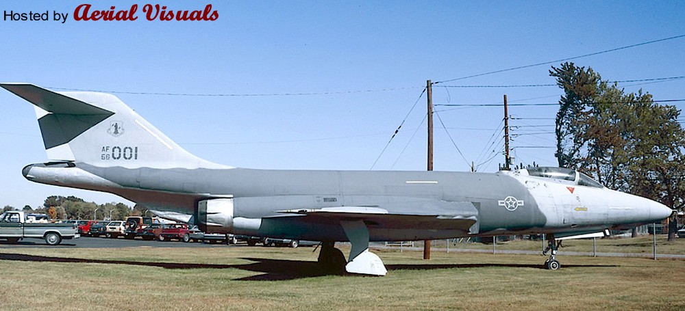
The McDonnell F-101 Voodoo was a supersonic jet fighter which primarily served the United States Air Force (USAF). Initially designed by McDonnell Aircraft as a long-range bomber escort (known as a penetration fighter) for the Strategic Air Command (SAC), the Voodoo was instead developed as a nuclear-armed fighter-bomber for the Tactical Air Command (TAC) and later evolved into an all-weather interceptor as well as into a reconnaissance platform.
The Voodoo's career as a fighter-bomber (F-101A and C) was relatively brief, but the reconnaissance fighter versions served for some time. Along with the US Air Force's Lockheed U-2 and US Navy's Vought RF-8 Crusaders, the RF-101 reconnaissance variant of the Voodoo was instrumental during the Cuban Missile Crisis and saw extensive service during the Vietnam War. Beyond original RF-101 single seaters, a number of former F-101A and Cs were, after the Vietnam era, converted into photo reconnaissance aircraft (as RF-101G and H) for the US Air National Guards.
Delays in the 1954 interceptor project (also known as WS-201A, which spawned to the troubled F-102 Delta Dagger) led to demands for an interim interceptor aircraft design, a role that was eventually won by the Voodoo’s B model. This new role required extensive modifications to add a large radar to the nose of the aircraft, a second crewmember to operate it, and a new weapons bay using a unique rotating door that kept its four AIM-4 Falcon missiles (two of them alternatively replaced by unguided AIR-2 Genie nuclear warhead rockets with 1.5 Kt warheads) semi-recessed under the airframe.
The F-101B was first deployed into service on 5 January 1959, and this interceptor variant was produced in greater numbers than the original F-101A and C fighter bombers, with a total of 479 being delivered by the end of production in 1961. Most of these were delivered to the Air Defense Command (ADC), the only foreign customer was Canada from 1961 onwards (as CF-101B), after the cancellation of the CF-105 Arrow program in February 1959. From 1963–66, USAF F-101Bs were upgraded under the Interceptor Improvement Program (IIP; also known as "Project Bold Journey") with a fire control system enhancement against hostile ECM and an infrared sighting and tracking (IRST) system in the nose in place of the Voodoo’s original hose-and drogue in-flight refueling probe.
The F-101B interceptor later became the basis of further Voodoo versions which were intended to improve the tactical reconnaissance equipment of the US Air National Guards. In the early 1970s, a batch of 22 former Canadian CF-101Bs were returned to the US Air Force and, together with some USAF Voodoos, converted into dedicated reconnaissance aircraft, similar to the former RF-101G/H conversion program for the single-seat F-101A/C fighter bombers.
These modified interceptors were the RF-101B and J variants. Both had their radar replaced with a set of three KS-87B cameras (one looking forward and two as a split vertical left/right unit) and a panoramic KA-56 camera, while the former missile bay carried different sensor and avionics packages.
The RF-101Bs were exclusively built from returned Canadian Voodoos. Beyond the photo camera equipment, they featured upgraded navigational equipment in the former weapon bay and a set of two AXQ-2 TV cameras, an innovative technology of the era. A TV viewfinder was fitted to the cockpit and the system was operated effectively from altitudes of 250 ft at 600 knots.
The other re-built reconnaissance version, the RF-101J, was created from twelve former USAF F-101Bs, all of them from the final production year 1961 and with relatively few flying hours. Beyond the KS-87B/KA-56 camera set in the nose, the RF-101J featured a Goodyear AN/APQ-102 SLAR (Side-looking airborne radar) that occupied most of the interceptor’s former rotating internal weapon bay, which also carried a fairing for a heat exchanger. The radar’s conformal antenna array was placed on either side of the lower nose aft of the cameras and allowed to record radar maps from view to each side of the aircraft and pinpoint moving targets like trucks in a swath channel approximately 10 nautical miles (11.5 miles/18 km) wide. To identify potential targets along the flight path for the SLAR and to classify them, the RF-101J furthermore received an AN/AAS-18 Infrared Detecting Set (IRDS). It replaced the F-101B’s IRST in front of the cockpit and was outwardly the most obvious distinguishing detail from the RF-1010B, which lacked this hump in front of the windscreen. The IRDS’ range was almost six miles (9.5 km) and covered the hemisphere in front of the aircraft. With the help of this cryogenically-cooled device the crewman in the rear cockpit could identify through a monitor small heat signatures like hot engines, firing weapons or campfires, even in rough terrain and hidden under trees.
Both new Voodoo recce versions were unarmed and received AN/APR-36 radar homing and warning sensors to nose and tail. They also had an in-flight refueling receptacle re-fitted, even though this was now only compatible with the USAF’s high-speed refueling boom system and was therefore placed in a dorsal position behind the cockpit. Furthermore, both versions received a pair of unplumbed underwing pylons for light loads, e. g. for AN/ALQ-101,-119 or -184 ECM pods, photoflash ejectors for night photography or SUU-42A/A Flares/Infrared decoys and chaff dispenser pods.
The RF-101Bs were delivered in 1971 and allocated to the 192d Tactical Reconnaissance Squadron of the Nevada Air National Guard, where they served only through 1975 because their advanced TV camera system turned out to be costly to operate and prone to failures. Their operational value was very limited and most RF-101Bs were therefore rather used as proficiency trainers than for recce missions. As a consequence, they were already phased out from January 1975 on.
The RF-101Js entered service in 1972 and were allocated to the 147th Reconnaissance Wing of the Texas Air National Guard. Unlike the RF-101Bs’ TV cameras, the AN/APQ-102 SLAR turned out to be reliable and more effective. These machines were so valuable that they even underwent some upgrades: By 1977 the front-view camera under the nose had been replaced with an AN/ASQ-145 Low Light Level TV (LLLTV) camera, sensitive to wavelengths above the visible (0.4 to 0.7 micrometer) wavelengths and ranging into the short-wave Infrared (usually to about 1.0 to 1.1 micrometer). The AN/ASQ-145 complemented the IRDS with visual input and was able to amplify the existing light 60,000 times to produce television images as clearly as if it were noon. In 1980, the RF-101Js were furthermore enabled to carry a centerline pod for the gigantic HIAC-1 LOROP (Long Range Oblique Photography) camera, capable of taking high-resolution images of objects 100 miles (160 km) away.
USAF F-101B interceptors were, as more modern and effective interceptors became available (esp. the F-4 Phantom II), handed off to the Air National Guard, where they served in the fighter role until 1982. Canadian CF-101B interceptors remained in service until 1984 and were replaced by the CF-18 Hornet. The last operational Canadian Voodoo, a single EF-101B (nicknamed the “Electric Voodoo”, a CF-101B outfitted with the jamming system of the EB-57E Canberra and painted all-black) was returned to the United States on 7 April 1987. However, the RF-101Js served with the Texas ANG until 1988, effectively being the last operational Voodoos in the world. They were replaced with RF-4Cs.
General characteristics:
Crew: Two
Length: 67 ft 5 in (20.55 m)
Wingspan: 39 ft 8 in (12.09 m)
Height: 18 ft 0 in (5.49 m)
Wing area: 368 ft² (34.20 m²)
Airfoil: NACA 65A007 mod root, 65A006 mod tip
Empty weight: 28,495 lb (12,925 kg)
Loaded weight: 45,665 lb (20,715 kg)
Max. takeoff weight: 52,400 lb (23,770 kg)
Powerplant:
2× Pratt & Whitney J57-P-55 afterburning turbojets
with 11,990 lbf (53.3 kN) dry thrust and 16,900 lbf (75.2 kN) thrust with afterburner each
Performance:
Maximum speed: Mach 1.72, 1,134 mph (1,825 km/h) at 35,000 ft (10,500 m)
Range: 1,520 mi (2,450 km)
Service ceiling: 54,800 ft (17,800 m)
Rate of climb: 36,500 ft/min (185 m/s)
Wing loading: 124 lb/ft² (607 kg/m²)
Thrust/weight: 0.74
Armament:
None, but two 450 US gal (370 imp gal; 1,700 l) drop-tanks were frequently carried on ventral
hardpoints; alternatively, a central hardpoint could take single, large loads like the HIAC-1 LOROP
camera pod.
A pair of retrofitted underwing hardpoints could carry light loads like ECM jammer pods,
flare/chaff dispensers or photoflash ejectors
The kit and its assembly:
This is another project that I had on my agenda for a long while. It originally started with pictures of an RF-101H gate guard in Louisville at Standiford Field International from around 1987-1991:
imgproc.airliners.net/photos/airliners/6/2/9/1351926.jpg?...
www.aerialvisuals.ca/Airframe/Gallery/0/41/0000041339.jpg
This preserved machine wore a rather unusual (for a Voodoo) ‘Hill’ low-viz scheme with toned-down markings, quite similar to the late USAF F-4 Phantom IIs of the early Eighties. The big aircraft looked quite good in this simple livery, and I kept the idea of a Hill scheme Voodoo in the back of my mind for some years until I recently had the opportunity to buy a cheap Matchbox Voodoo w/o box and decals. With its optional (and unique) RF-101B parts I decided to take the Hill Voodoo idea to the hardware stage and create another submission to the “Reconnaissance and Surveillance” group build at whatifmodellers.com around July 2021: an ANG recce conversion of a former two-seat interceptor, using the RF-101B as benchmark but with a different suite of sensors.
However, the Matchbox Voodoo kit is rather mediocre, and in a rather ambitious mood I decided to “upgrade” the project with a Revell F-101B as the model’s basis. This kit is from 1991 and a MUCH better and finely detailed model than the rather simple Matchbox kit from the early Eighties. In fact, the Revell F-101B is actually a scaled-down version of Monogram’s 1:48 F-101B model kit from 1985, with many delicate details. But while this downscaling practice has produced some very nice 1:72 models like the F-105D or the F-4D, the scaling effect caused IMHO in this case a couple of problems. Revell's assembly instructions for the 1:72 kit are not good, either. While the step-by-step documentation is basically good, some sketches are so cluttered that you cannot tell where parts in the cockpit or on the landing gear are actually intended to be placed and how. This is made worse by the fact that there are no suitable markings on the parts – you are left to guessing.
Worse, there is a massive construction error: the way the wings section is to be assembled and mounted to the hull is impossible! The upper wing halves have locator pins for the fuselage, but they are supposed to be glued to the lower wing half (which also encompasses the aircraft's belly) and the mounted to the hull. The locator pins make this impossible, unless you bend the lower wing section to a point where it might warp or break, or you just cut the pins off - and live with some instability. Technically the upper wing halves have to be mounted to the fuselage before you glue the lower wing section to them, but I am not certain if this would work well because you also have to assemble the air intakes at the same time “from behind”, which is only feasible when the wings have already been completed but still left away from the fuselage. It’s a nonsense construction! I cannot remember when I came across a kit the last time with such an inherent design flaw?
Except for the transplanted RF-101B nose section, which did not fit well because the Matchbox Voodoo apparently has a more slender nose, the Revell kit was built mostly OOB. However, this is already a challenge in itself because of the kit’s inherent flaws (see above), its complex construction and an unorthodox assembly sequence, due to many separate internal modules including the cockpit tub, a separate (fully detailed) front landing gear well, a rotating weapon bay, air intakes with complete ducts, and the wing section. A fiddly affair.
Only a few further changes beyond the characteristic camera fairing under the radome were made. The rotating weapon bay was faired-over with the original weapon pallet, just fixing it into place and using putty to blend it into the belly. The small underwing pylons (an upgrade that actually happened to some late Voodoos) were taken from a vintage Revell F-16. The SLAR antenna fairings along the cockpit flanks were created with 0.5mm styrene sheet and some PSR. They are a little too obvious/protruding, but for a retrofitted solution I find the result acceptable. The drop tanks came from the Revell kit, the underwing ordnance consists of an ALQ-119 ECM pod from a Hasegawa aftermarket set and a SUU-42 dispenser, scratched from a Starfighter ventral drop tank, bomb fins and the back of a Soviet unguided missile launcher.
Painting and markings:
Very simple and basic. While I originally wanted to adopt the simple two-tone ‘Hill’ scheme from the gate guard for my fictional Voodoo, I eventually settled for the very similar but slightly more sophisticated ‘Egypt One’ scheme that was introduced with the first F-16s – it just works better on the F-101’s surfaces. This scheme uses three grey tones: FS 36118 (Gunship Gray, ModelMaster 1723) for the upper wing surfaces, the “saddle” on the fuselage and the canopy area with an anti-glare panel, FS 36270 (Medium Grey, Humbrol 126) on the fin and the fuselage area in front of the wing roots, and FS 36375 (Light Ghost Grey, Humbrol 127) for all lower surfaces, all blended into each other with straight but slightly blurred edges (created with a soft, flat brush). The radome and the conformal antennae on the flanks became Revell 47 for a consistent grey-in-grey look, but with a slightly different shade. The model received an overall black ink washing and some post panel shading, so that the large grey areas would not look too uniform.
As an updated USAF aircraft I changed the color of the landing gear wells’ interior from green zinc chromate primer to more modern, uniform white, even though the red inside of the covers was retained. The interior of the flaps (a nice OOB option of Revell’s kit) and the air brakes became bright red, too.
The cockpit retained its standard medium grey (Humbrol 140, Dark Gull Grey) interior and I used the instrument decals from the kit – even though these did not fit well onto the 3D dashboards and side consoles. WTF? Decal softener came to the rescue. The exhaust area was painted with Revell 91 (Iron) and Humbrol’s Steel Metallizer (27003), later treated with graphite for a dirty, metallic shine.
Markings/decals primarily come from a 1:72 Hi-Decal F-4D sheet that contains (among others) several Texas ANG Phantoms from the mid-Eighties. Some stencils were taken over from the original Voodoo sheet, the yellow formation lights had to be procured from a Hasegawa F-4E/J sheet (the Matchbox sheet was lost and the Revell sheet lacks them completely!). The characteristic deep yellow canopy sealant stripes came from a CF-101 sheet from Winter Valley Decals (today part of Canuck Models as CAD 72008). I was lucky to have them left over from another what-if build MANY moons ago, my fictional CF-151 kitbashing.
Everything went on smoothly, but the walkway markings above the air intakes became a problem. I initially used those from the Revell sheet, which are only the outlines so that the camouflage would still be visible. But the decal film, which is an open square, turned out to be so thin that it wrinkled on the curved surface whatever I tried, and what looked like a crisp black outline on the white decal paper turned out to be a translucent dark blue with blurry edges on the kit. I scrapped them while still wet… Enter plan B: Next came the walkway markings from the aforementioned Winter Valley sheet, which were MUCH better, sharper and opaque, but they included the grey walking areas. While the tone looked O.K. on the sheet it turned out to be much too light for the all-grey Voodoo, standing out and totally ruining the low-viz look. With a bleeding heart I eventually ripped them off of the model with the help of adhesive tape, what left light grey residues. Instead of messing even more with the model I finally decided to embrace this accident and manually added a new black frame to the walkway areas with generic 2mm decal stripe material from TL Modellbau The area now looks rather worn, as if the camouflage had peeled off and light grey primer shows through. An unintentional result, but it looks quite “natural”.
The “Rhino Express” nose art was created with Corel Draw and produced with a simple inkjet printer on clear decal sheet. It was inspired by the “toenail” decoration on the main landing gear covers, a subtle detail I saw IIRC on a late CF-101B and painted onto the model by hand. With its all-grey livery, the rhino theme appeared so appropriate, and the tag on the nose appeared like a natural addition. It’s all not obvious but adds a personal touch to the aircraft.
Finally, after some more exhaust stains had been added to various air outlets around the hull, the model was sealed with matt acrylic varnish, position lights were added with clear paint and the camera windows, which had been created with black decal material, received glossy covers. The IRST sensor was painted with translucent black over a gold base.
Well, while the all-grey USAF livery in itself is quite dull and boring, but I must say that it suits the huge and slender Voodoo well. It emphasizes the aircraft's sleek lines and the Texas ANG fin flash as a colorful counterpoint, as well as the many red interior sections that only show from certain angles, nicely break the adapted low-viz Egypt One livery up. The whole thing looks surprisingly convincing, and the subtle rhino markings add a certain tongue-in-cheek touch.
Twin-head large EDM CNC sparking machine has two separated spindle heads and two separated controllers, also called double column CNC EDM machine, it was developed for some kinds of molds with very large size. Max table size could be up to 3500mm, and load capacity up to 20000kgs. Besides, two separated CNC electric discharge machines could be performed at the same on different locations of one mold. Of course, the dynamic and mechanical of double head CNC EDM is not as good as single-head CNC EDM die sinking EDM machine.
A1470 Double Heads CNC EDM Sinker
A1880 Double Heads CNC RAM EDM Machine
A2180 Double Heads Large Sinker EDM
A2510 Double Heads Die Sinking EDM Machine
Double Heads Large CNC EDM Machine Highlights
5th generation EDM machining control system.
Double heads with the capacity of two separated machining at the same time.
Smart expert database.
Excellent performance of both cooper and graphite electrode machining.
Min machining current 0.1A.
Best surface finish Ra≤0.2µm.
Min. wear of electrode ≤0.05%.
2 years of aging treatment of casting of the machine.
Ram type structure, fixed working table, heavy load capacity.
Obtained national design patent of rotary panel cabinet.
Man-machine engineering friendly.
Optimized high-frequency power control system.
Most efficient control circuits.
Machine body had been analyzed by finite element analysis.
High-quality casting with enhanced structural ribs.
Double Heads Large CNC EDM Machine Function Configuration of Controller
No.Function explanation
1LCD, touch screen input
2Simultaneous three-axis control(optional 4-axis simultaneous control)
3Super finish PIKA machining circuits-mirror surface machining function; fine current control circuits with better performance of large-area super finish machining, at the same time, excellent performance of corner clearing
4Expert machining parameters database: with high explosive power circuit, especially good for processing hard ally material)
Automatic and manual machining according to a different combination of a different material of electrode and workpiece: copper/steel, graphite 1/steel, graphite 2/steel, silver-tungsten/steel, copper-tungsten/steel, silver-tungsten/hard alloy, copper/zinc alloy, graphite/zinc alloy, copper/copper alloy.
5AUTO machining function:
Input material of electrode and workpiece, machining area, shrinkage of the electrode, required surface finish and etc Then control system automatically calculates machining parameters from rough machining to finish machining according to the expert database.
6Automatic positioning function:
End face positioning, cylinder center positioning, corner positioning, inner hole positioning, random three points positioning, discharging position self-decided positioning and etc.
7Online measuring function:
Utilize automatic positioning function to do the online measuring and amending to the machined workpiece.
8Automatic arcing removing circuit:
Real-time monitoring on the discharging status, if any tiny short circuit or arcing happens, the system would remove arcing and give the alarm
9Safety control function:
Overload protection, code grammar detecting, oil level control, oil temperature control, automatic fire extinguisher
10Power-off recovery function:
The system can remember the present position of coordinate when suddenly power-off happens, the present position can be kept.
DIE SINKER EDM MACHINE FAQS
The Mostly Asked Questions about Die Sinker EDM Machines
What's EDM die sinking machining (EDM forming machining)?
The EDM die sinker machine is able to cope machining by prepared electrodes, the cavity that created is the same as the profile of the electrode. EDM spark erosion machining can process punches, drawing dies, and extension dies of various types of holes; process various forging dies, extrusion dies, plastic injection molds and extrusion dies; and also process various small holes, deep holes, heterosexual holes, and curved holes, and special materials with complex-shaped parts, etc.
Uses of EDM machining technology
(1) Processing various technologies and their alloy materials, conductive super-hard materials (such as polycrystalline diamond, cubic boron nitride, cermets, etc.), special heat-sensitive materials, semiconductor, and non-semiconductor materials.
(2) Processing various kinds of complex-shaped hole and cavity workpieces, including processing round hole, square hole, polygon hole, special-shaped hole, curved hole, threaded hole, micro hole, deep hole and other type hole workpieces, as well as various types Face cavity workpiece. For example, processing exceptionally large molds and parts ranging from a few micrometers of holes and grooves to several meters.
(3) Cutting of various workpieces and materials, including cutting of materials, cutting of parts with special structure, cutting of fine narrow slits and parts composed of fine narrow slits (such as metal grid, slow wave structure, heterogeneous orifice spinneret, laser Pieces, etc.).
(4) Processing all kinds of forming parts such as forming knives, samples, tools, measuring tools, threads and so on.
(5) Grinding of workpieces, including small holes, deep holes, inner circles, outer circles, flat surfaces, etc. and profile grinding.
(6) Engrave and print nameplates and marks.
(7) Surface strengthening and modification, such as high-speed quenching of metal surfaces, nitriding, carburizing, coating of special materials and alloying, etc.
(8) Auxiliary uses, such as removing taps and drill bits from parts in this segment, repairing worn parts, etc.
What is the EDM machine meaning in the metal working industry
Electrical spark erosion, also known as electrical discharge machining and electrical corrosion machining, called electrical discharge machining in Japan and electrical corrosion machining in the former Soviet Union. It is a method of processing the metal workpiece by utilizing the phenomenon of electric corrosion generated during the pulse discharge between the two poles (electrode and workpiece, should be conductive). Academically it belongs to the category of electrophysical processing. EDM technology is one of the most important parts of special machining technology.
What is the advantage of electrical discharging machining against traditional metal working method?
Answer: With the development of industrial production and the advancement of science and technology, more and more new materials with a high melting point, high hardness, high strength, high brittleness, high viscosity, high toughness, high purity and other properties continue to appear, and also some with various complex structures that can’t be machined by traditional metal working method, sometimes difficult or impossible to process. With traditional metal working technology.
Therefore, in addition to further development and improvement of traditional mechanical metal working methods, people also strive to find new processing methods. The electrical discharging machining (EDM) method can meet the needs of development, and shows many excellent performances in the application, so it has been rapidly developed and increasingly widely used.
Characteristics of EDM die sinking machining
(1). During machining, the tool electrode and the workpiece material are not actually touching and there is basically no macro-mechanical force between the two. Therefore, the "soft" tool electrode can be used to process the "hard" workpiece. For example, graphite and copper electrodes can process hardened steel, cemented carbide, and even diamond.
(2). Because the spark energy density of the high-frequency power discharging can be accurately controlled, and there is no macro mechanical force between the two poles (electrode and workpiece), so the precise and fine machining can be achieved. Such as the processing of narrow slits, narrow grooves, micro-small holes of molds and parts, the processing accuracy can reach micron level, even sub-micron level.
(3) "Copying". With direct use of electrical power for processing, it is easy to realize the automation, intelligence, and application of modern computer control technology to precisely control the machining process, which makes the machining of workpieces more realistic.
(4) Direct use of electrical energy for processing, which is convenient for automation of the machining process, and can reduce mechanical processing procedures, shorten processing steps, low labor intensity, and easy to use and maintain
www.dmncedm.com/products/double-heads-large-cnc-edm-machine/
Object(s) Details: With Mars lying less than 2 degrees from the waning gibbous Moon earlier this week and coinciding with a break in the weather, I took the opportunity to try to image both objects together, as well as separately.
As such, the attached composite shows how they appeared together in a single frame shot (top) and individually using a much longer focal length system (bottom). For comparison of angular size, I tried to keep the Mars & Moon images at bottom all at the same 'image / magnification' scale (of course in the wider-field view Mars is a point-like object). This was also the first image I've posted which contains a blending of data from the IR filter (used for 'brightness / contrast') with the luminence filter (used for 'color'). Although all of the images can certainly use quite a lot of improvement, I was fairly pleased with the results.
Image Details: Taken by Jay Edwards at the HomCav observatory on the morning of August 9, 2020 from 06:26 to 07:27 UT (02:26 to 03:27 EDT) using an Orion ED80T Cf (i.e. an 80mm f/6 carbon-fiber triplet apochromatic refractor) and 0.8 X Televue field falttener / focal reducer with a Canon 700D (top image) and a vintage 1970 8-inch, f/7 Criterion newtonian reflector and 3X Televue barlow with a ZWO ASI290MC planetary camera / auto-guider. With the 80MM piggybacked on the newt. the scopes were tracked using a Losmandy G-11 running a Gemini 2 control system.
The 80mm wide-angle shot is a single frame taken at ISO 100 using a 1/200 sec exposure, while the Mars & lunar images at bottom using the 8-inch newt. are a stack of selected frames from video clips utilizing various filters and consisting of a total of over 40,000 frames.
Processed using a combination of AS3, Registax & PSP, as presented here the entire composite has been resized down to HD resolution (approx. 1/2 their original size) and where applicable the bit depth has been lowered to 8 bits per channel.
An E-3G Airborne Warning and Control System aircraft of the 552nd Air Control Wing, 960th Airborne Air Control Squadron, is prepared during the early morning hours of Sept. 15, 2018, for a response to Hurricane Florence mission at Tinker Air Force Base, Oklahoma. The AWACS will provide air control and de-confliction service along the East Coast of the United States as they monitor and control airspace as local, state and federal assets move in to the area to conduct rescue and recovery operations. (U.S. Air Force photo/Greg L. Davis)
Object Details: Subject: M5 is a globular star cluster consisting of between 100,000 and 500,000 stars. With a diameter of about 165 light-years, it lies 24,500 light-years from Earth. Being approximately 12 billion years old it is one of the oldest globular clusters in the Milky Way (and also one of the largest). Located in the constellation of Serpens Caput, at magnitude 5.7, it is actually faintly visible to the naked eye under ideal conditions and is easily visible in binoculars in even reasonably dark skies.
Image Details: The attached is a relatively short stack of 25 one-minute exposures at ISO1600. The data was taken on the evenings of May 13 & 14, 2021 by Jay Edwards at the HomCav Observatory in Maine, NY using an 8-inch, f/7 Criterion newtonian reflector (which having been manufactured on May 14, 1970 celebrated it's 51st year of service that day). Connected to an unmodded Canon 700D (t5i) at prime focus, the camera was controlled by AstroPhotographyTool (APT).
Since I tend to shoot simultaneously using twin unmodded Canon 700D (t5i) DSLRs, I also took wide-field images using an 80mm f/6 carbon-fiber triplet apochromatic refractor (i.e. an Orion ED80T CF) connected to a Televue 0.8X field flattener / focal reducer and a twin identical unmodded Canon 700D; but have yet to examine those, nor the shots of M5 I took with both optical systems later each of those two evenings.
The 80mm was piggybacked on the 8-inch, along with an 80MM f/5 Celestron 'short-tube' doublet (for guiding) as well as a few other items (e.g. a CCD & wide-field camera lens, etc.). These optics were tracked using a Losmandy G-11 mount running a Gemini 2 control system and guided using PHD2 to control a ZWO ASI290MC planetary camera / auto-guider in the afore-mentioned 80mm doublet.
Processed using a combination of PixInsight and PaintShopPro, as presented here the image is nearly 'full frame', having only had the edges cropped slightly & it's vertical edges cropped to match an HD format. It was then re-sized down to HD resolution and the bit depth was lowered to 8 bits per channel.
Given the relatively short 25 minute exposure, I was fairly pleased with the result and am looking forward to seeing what the wide-field images may show, as well as the wide-field M3 shots I was lucky to catch those same evenings (a shot of M3 through the 8-inch taken those same evenings can be found at the link attached here -
www.flickr.com/photos/homcavobservatory/51200369117/
Although the majority of the stars in M5 formed about 12 billion years ago (by comparison our Sun is 'only' 5 billion years old), and given the fact that more massive stars consume their fuel at a much faster rate and therefore die out relatively quickly ending their lives in massive supernova explosions, this should have left M5 with only old low-mass stars. However the detection of a population of younger stars known as 'blue stragglers' indicates that they are a result of interactions such as stellar collisions - talk about spectacular fireworks ! ;)
Wishing all my fellow Americans a Happy Fourth Of July !!!
The highlight of the late summer bank holiday weekend was that of 1952 Roberts-built Coronation tramcar 304 making a much-anticipated return to the Blackpool Promenade, the result of a years' work by Brian Lyndop to jump through all the necessary hoops such as electricial safety, engineering assesments and training due to the different control system inside this tram, as well as type training for the drivers (of which several drivers gave up their own free time to train up to drive this tram). 304 starred on TV in Channel 4's 'Salvage Squad' program where it underwent a full restoration back to original condition, and was originally one of 25 from this class of graceful tram built by Charles Roberts & Co between 1952-1954 (this being built in 1952) for use along the promenade. What makes this tram special is that it still retains its original VAMBAC control system (Variable Automatic Multinotch Braking and Acceleration Control) which was a British development of an American design which had been used in trams such as, I believe, the PCC cars in San Francisco - and worthy of note is that the equipment from 304 went on show for the Festival of Britain in 1951... whilst I am not sure how the system actually works, the concept was to provide smoother acceleration and braking all through just a single control lever. The problem though was that the system required lots of ventilation, and open vents to electrical systems beside a west-facing seafront isn't a particularly good combination - sand and water would enter the mechanism and would short circuit on the acceleration side, whilst at other times there were issues with the brakes not working (though this might have been caused more by something else, read on...). The Coronation trams (or 'Spivs' as the platform staff called them) had four motors instead of the usual two seen on other trams - these were not just to haul around the exceptionally heavy tramcar around (each tram weighed in at a staggering 20 Tons), but also to provide enough power for good acceleration and a good top speed - the problem though was that this could never really be utilised because the trams got caught behind the previous service (the original idea had been to replace Balloons with these on a higher frequency service - sounds familiar to modern day bus route planning)... the other problem with the four motors was how thirsy they were on the electricity; many time they would draw so much current they would trip the breakers in the substations, rendering a whole section of the tramway (and therefore any trams on it) dead and immobile. The heavy body led to several axles fracturing in addition to wheelsets breaking (these being rubber-sandwiched sets and so needed specialist attention and more frequent maintenance), whilst the roofs were prone to leaking - 304 was the very first Coronation delivered, and it was even said at the time that the roof was leaking even whilst it was being taken off the low-loader on delivery.
To cut down on their weight, the steel panels of the trams (which, it should be noted, were built by a company more familiar with railway wagons) were replaced by aluminium ones, and I believe there may have been upward-facing skylights which were panelled over too, whilst the heavyweight batteries providing backup power to the VAMBAC system were removed entirely to save further weight... the problem with this idea was that the batteries kept the system ticking over when the tram was on a neutral section of unpowered track (a neutral section being the divide between the overhead power coming from different substations), and by removing them the VAMBAC system reset everytime the tram went through a neutral section; what this meant was that if the tram went through the section whilst braking, the system reset and the brakes came off regardless of the position of the control lever - to get the brakes to work again, the control lever had to put back to position 0 and then put back ninto the braking positions: in some cases there simply wasn't enough time to do this, and on other occasions the driver was unaware of this and so the tram was reported as having a full brake failure. All of these problems led to most trams losing their VAMBAC controls in about 1963-65 in favour of more traditional Z-type controllers salvaged from English Electric Railcoaches, the converted Coronations being referred to as "Z Cars". In 1968 the class were renumbered, and 304 became 641 (the series was 641-664) but by this time were already being withdrawn and some of them scrapped; by 1971 only 660, 641 and 663 remained (the latter two having gone off to museums whilst 660 had been preserved by Blackpool Transport). 313 had been the first to be scrapped, in 1965 and so never saw itself renumbered. The last Coronation ran in normal service in 1975.
The Coronations were by far the most luxurious trams on the Blackpool system, but were also by far the most expensive. due to problems with the control system and specialised equipment, repair bills went through the roof; meanwhile the debt to buy these trams in the first place was still not even paid off when the entire class had been withdrawn from service! And all the problems associated with these trams brought the system to its knees and almost saw it off. However, the class had still remained popular with passengers and so forward-thinking preservation groups managed to save representatives from the group so future generations could enjoy their good looks and smooth ride.
304 was stored at Blackpool until 1975 when it was moved to the National Tramway Museum store at Clay Cross. Later it moved to Burtonwood after being acquired by the Merseyside Tramcar Preservation Society for use on a possible heritage tramway in Bewsey, Warrington. No progress was made and in 1984 the MTPS decided to concentrate resources on their preserved Liverpool trams and No. 304 passed to the Lancastrian Transport Group.
It was moved to the St.Helens Transport Museum in 1986 and restoration work started in 1993. This involved underframe overhaul, new flooring and a complete rewiring, partly funded by the Fylde Tramway Society. Work stalled following access restrictions at the St. Helens site but in 2002 the tram was selected as a project to feature in Channel 4's "Salvage Squad" series.
No. 304 returned to Blackpool Transport's depot in June 2002 for an intensive period of restoration work that culminated in the tram returning to the Promenade rails on 6th January 2003 for the finale of the Salvage Squad filming. The programme was broadcast on 17th February 2003 and was watched by over 2.5 million viewers.
In this photo, 304 is heading onto the passing loop at the Fleetwood ferry terminal, back on the tramway for the very first time in several years in revenue-earning service on Heritage special services; it is running the final daytime Heritage service to close down the 2014 season, this being the late afternoon trip to Fleetwood and back.
The small holes (3 pointing down, 2 pointing aft and 4 out to the side) are vernier thrusters, used for very small movements of the space shuttle in orbit. They are too weak to work in atmosphere. The larger nozzle about them is one of 2 orbital maneuvering engines, they move the shuttle from higher to lower orbits (and vice cersa). They also perform the deorbit burn that takes the shuttle out of orbit when it is time to come home. The large nozzle on the left is one of 3 space shuttle main engines (SSMEs), the engines that use fuel from the external tank at lift off and get the shuttle to orbit (along with the solid rockets boosters). Once the external tank is jettisoned, the shuttle uses the orbital manvering engine and thrusters.
NASA didn't clean up the shuttle a bit after her last flight, you can easily tell this bird has been through the atmosphere the hard way.
As early as the 1950s, IBM programmers were working on software for things like submarine control systems and missile tracking systems, which were so complex that they could not be conceived and built in one go. Programmers had to evolve them over time, like cities, starting with a simple working system that could be tested by users, and then gradually adding more function and detail in iterative cycles that took one to six months to complete. In a 1969 IBM internal report called simply “The Programming Process,” IBM computer scientist M.M. Lehman described the approach:
“The design process is… seeded by a formal definition of the system, which provides a first, executable, functional model. It is tested and further expanded through a sequence of models, that develop an increasing amount of function and an increasing amount of detail as to how that function is to be executed. Ultimately, the model becomes the system.”
This iterative approach to software development, where programmers start by creating a simple, working seed system and expand it in subsequent cycles of user testing and development, has become a common approach in software design, known under a variety of names such as iterative development, successive approximation, integration engineering, the spiral model and many others, but in 2001, when a group of prominent developers codified the core principles in a document they called the Agile Manifesto, they gave it the name “agile” which seems to have stuck.
Agile is about small teams that deliver real, working software at all times, get meaningful feedback from users as early as possible, and improve the product over time in iterative development cycles. Developing software in an agile way allows developers to rapidly respond to changing requirements. Agile developers believe that where uncertainty is high there is no such thing as a perfect plan, and the further ahead you plan, the more likely you are to be wrong.
From 1933 to 1990, Reimar Horten, assisted by his brother, Walter, designed and built a series of swept-wing aircraft without fuselages or tails and they did not use any other surfaces for control or stability that did not also contribute lift to the wing. The National Air and Space Museum owns a Horten II L, Horten III f, Horten III h, Horten VI V2, and the Horten IX V3 turbojet interceptor.
Reimar Horten continued to refine the all-wing sailplane with his third design, the Horten III. Compared to the H II, the wingspan grew about 4 m (13 ft 3 in) but the root chord decreased by .25 m (9 in). By narrowing the root chord and lengthening the wings, Horten increased aspect ratio and this trend continued with Horten's next two sailplane designs. Like the Horten II, the H III center section consisted of welded steel tubes covered with plywood and sheet metal. Horten built the wings entirely from wood. He refined the flight control system by adding a second set of elevons.
From July 1938 until October 1944, at least eighteen Horten III aircraft were constructed at Köln, Berlin, Fürth, Giebelstadt, Minden, Bonn, and Göttingen. This model was built in greater numbers than any other Horten design and both Horten brothers and other pilots flew Horten III gliders in the German national glider competition in 1938 and 1939. Reimar successfully motorized several Ho III sailplanes using a variety of powerplants including Walter Mikron and Volkswagen engines. Horten also modified an Ho III b to carry ammunition in support of Operation Sealion, the proposed invasion of England.
Horten fitted the NASM Horten III f with a flat-prone couch for the pilot. This wing, the Horten VI-V3, and the Wright brothers 1903 Flyer are the only aircraft in the NASM collection configured for prone pilotage. Other nations built aircraft to test this unique layout but these NASM artifacts are among the few examples known to exist today. Horten had experimented with seating position to reduce drag as early as 1935 when he designed the first Horten II with supine seating and flew it in May. At first the seatback in the Horten II was inclined just 18º to the horizon but a 23º position became standard. Even with the pilot's head more upright at this setting, visibility was dangerously limited particularly in the slow speed/high-angle-of-attack regime sailplane pilots often operated in. As Reimar put it, the "main drawbacks are poor forward visibility (even worse to the rear), the pilot's knees being in the field of vision, and difficulties developing proper [control] feel and coordination" (quoted in Reimar Horten, "Flying Wing Pilot Position and Design Options," "Soaring," August 1980, translated by Jan Scott, 23).
Supine seating proved a dead end until the postwar revival but in 1938, work at the Akademische Fliegergruppe Stuttgart led Horten in a new direction. The institute built the all-wood Fs 17 with a flat-prone cockpit to conduct aero medical research on pilots subjected to high-G maneuvers. Reimar saw in the new layout intriguing possibilities for drag reduction. In 1941 he completed the Horten IV, the first all-wing aircraft equipped for prone pilotage. Reimar and Walter Horten intended to acclimate pilots to the prone position by using gliders such as the NASM Horten III f. They hoped to smoothly transition pilots to high-performance Horten aircraft equipped with prone cockpits. These "hot rod" Hortens included the H IV and H VI sailplanes, and the jet-propelled H X.
In spring 1944 at Göttingen, a young mathematician named Karl Nickel sampled the prone layout when he flew a Horten III f (it is not known if this same airplane is now in the NASM collection). Nickel's skeptical friends sounded the alarm. How could a pilot maintain proper 'feel' for the aircraft, whether it was banking slightly left or right, while lying on his stomach? It would be impossible, they claimed, to fly instinctively! The controls could not be moved unless the pilot carefully considered each movement beforehand. What of the pilot's personal comfort? Cross-country glider flights often lasted for hours. Even a thick-necked flyer could not hold his head, particularly in high-G thermalling turns. Blood would pool and the limbs would fall asleep! After landing the stiff, immobile pilot would be unable to hoist himself from the prone couch!
Dr. Nickel's fascinating report appears in Karl Nickel and Michael Wohlfart, "Tailless Aircraft in Theory and Practice (AIAA, 1994) on pages 351-355. It conveys his thoughts and feelings as he flew an all-wing Horten glider from the prone position. "I climb from behind [the aircraft] on the center-section of the flying wing to step inside and lie down in it." His parachute hung across his chest and the packed canopy pillowed his torso. The "lying-trough," he continued, "is well-upholstered with foam rubber and artificial leather. . . there is the chinrest which is easily adjustable. The designer has thought of everything and wants to accommodate the pilot in comfort." Horten had fitted seat belts but their operation was unorthodox. "They are fastened over the back and are released automatically as soon as the cockpit is opened. How Practical!"
The prone position demanded a novel control system. Reimar designed one and installed it in all his prone aircraft. He used a yoke-type wheel to transmit pitch and roll inputs to the elevons. Nickel continues: "For fore and aft movements [the wheel] slides back and forth on almost frictionless bearings along a horizontal tube. Will it be possible," he wondered, "to get quickly accustomed to this?" Once airborne, Dr. Nickel had the answer.
"All of a sudden I am completely baffled: there is nothing unusual, it's exactly as flying while sitting in a seat! I feel the stick force, the sailplane reacts to the smallest control movements. I completely forget that I am lying horizontally in space, that the control column [wheel] looks so strange, that the H III is no normal aircraft."
"[It is as though] I had been flying in prone position for years. . . The first gusts are felt and are counteracted automatically, without thinking. I see my hands moving to act in the correct way, but there is no conscious command from the brain. The bird feels good . . . [and this] reaction comes so strong and unexpected that I wish to sing at once. . . I am so delighted . . . there is nothing to learn about prone flying and everything is so simple. But don't start celebrating too early! We [glider and towplane] just crossed the airport boundary as some heavy gusts arrived. No problem to counteract them, but the result is astonishing: suddenly the tow-rope approaches me at full speed, collides with the canopy and disappears aft [the towpilot released his end of the tow rope]. Instinctively my arm shoots up to protect my head, even though it's unnecessary. Next reaction, release the rope too. In front of me lies an "inviting" high-tension line. Hence push [the wheel to maintain speed], [execute a] 180° turn and with the aid of a tailwind, [fly] back over the fence [airport boundary]. Is there enough altitude for a second turn into the wind [to set up for landing]? There better be; carefully "scraping" the turf a flat turn [at very low altitude] is achieved, [landing] skid lowered, no brake necessary, hold off, and here we are back at the starting point of the flight. Ugh!!!"
A half-hour later he was back in the air: "I am floating again in the air . . . flying over the houses and streets of Göttingen. Wonderful, this marvelous view down through the acrylic glass pane. Exactly as on a street map I can track the roads and alleys with my finger. Seemingly just in front of my face there is that hive of activity. Magnificent to soar and glide high over the rooftops, horizontal in space like a bird. This sort of flying really is the only natural way, how could anybody doubt it ever? The view is unobstructed on all sides through the large canopy, but the most astonishing aspect is the excellent view downward. Slowly we are losing altitude. It's time for a thermal to appear. Oops, here it is. Rudder and aileron, slowly pull up, it's just the same as with any other sailplane. Only the banking at first seems to be excessively large . . ."
Nickel initially made excessively shallow, flat turns but after two hours of practice, he adjusted. His mind began to accept and trust the new sight-picture of a standard turn presented by the Horten III f prone position. Banking turns of 60° became easy and "remained the only difficulty I encountered and it didn't occur anymore during later flights." As he built time flying prone, Nickel considered the problem of pilot comfort on long flights.
"Well, after two hours no bodily strain could be felt, but this could perhaps come with longer flights? . . . on the 7th of August 1943, a comparision test was made. . . Hermann Strebel made the first motorless flight of more than 10 hours in prone position with the Horten H IV over the Wasserkuppe mountain. At the same time I myself [flew] for 7 ½ hours in the [Olympia Meise glider]. [Strebel and I were] quite happy together up there, even though he could often out-fly me because of the better performance of his sailplane. After landing I went to him limping with aching backside. But he approached me laughing and completely fresh and could only shake his head to my envious questions: "No, no bruises, no limbs which went to sleep, no stiffness of the neck, nothing!"
Nickel found other reasons to like the prone pilot position. " . . . for tailless sailplanes the prone position is appropriate. . . The main reason for this is the better view of the outside world . . . This is important in particular during aero-tow. Especially with tailless sailplanes a good view of the towing aircraft can be decisive against flying too low and, consequently, being dragged down by the downdraft behind the tow aircraft."
The H III also had good handling qualities and this no doubt boosted Nickel's enthusiasm for the prone layout. He often witnessed Heinz Schiedhauer putting the Horten III d motorglider through its paces at Göttingen in 1943-44. During Schiedhauer's routine, "he did a flyby a few meters above the ground and, just in front of the onlookers, pulled back the stick abruptly. This created a 'whip stall' with a nearly vertical attitude. There was no tail-slide or roll-off, but rather the flying wing fell down into the normal flying position without loss of altitude and continued her horizontal flight."
Horten assigned Werk Nr. 32 to a Horten III f built in 1944 at Göttingen. The NASM III f may be the last of three 'f' subtypes built. All three aircraft featured prone cockpits for minimum drag. The pilot stretched flat on his stomach, bent slightly at the waist and knees, feet resting on rudder pedals hinged above his heels. A padded chin rest supported his head, which projected into the leading edge of the wing. Clear plastic panels formed the leading edge for several feet above, below, and to either side of the pilot. Visibility was excellent and drag greatly reduced. The wing had a maximum speed of 210 km/h (130 mph) and a best glide speed of 63 km/h (39 mph).
Details about the operational history of this glider remain unknown. One month after the war ended, a team of aviation experts working for the C. I. O. S. (Combined Intelligence Objectives Subcommittee) found both the NASM H III f and the H III h. The gliders were recovered "in perfect condition in trailers, with a [sic] full set of instruments" at Rottweil, Germany, on the Neckar River, approximately 60 miles (100 km) southwest of Stuttgart on June 11, 1945.
For a time, the United States Army Air Forces' Air Technical Intelligence (ATI) branch was interested in Horten flying wing aircraft. ATI assigned inventory control numbers to track the thousands of pieces of German military aircraft, equipment, and hardware obtained during and after the war. The following numbers identified Horten gliders now part of the NASM collection:
Horten II L - T2-7
Horten III f - T2-5042
Horten III h - T2-5039
Horten VI V2 - T2-5040
Inexplicably, ATI lost interest and declared "the Horten Tailless Gliders are of no value to us," according to the "Weekly Activity Report - Technical Intelligence - Week Ending 26 June 1945." The H III f and 'III h vanish into an historical black hole for the next two years. The story resumes on October 22, 1947, when Stanley A. Hall wrote a report called "Horten Tailless Sailplanes." Hall explained that the U. S. Air Force loaned the Horten III f, III h, and VI V2 to the Northrop Aeronautical Institute, across the road from the Northrop Aircraft Company in Hawthorne, California. This loan answered a "joint petition of Northrop Aircraft Inc., and the Southern California Soaring Association [SCSA]." The two organizations wanted the sailplanes "for purposes of inspection by West Coast engineers who, in interests of the development of all-wing aircraft, sought for evidence of similarity between the design practices of American and German engineers."
Northrop personnel planned to test-fly the two Horten III gliders but they arrived "damaged beyond reasonable repair [and] too badly damaged to make photography worthwhile." Despite their condition, a throng of aeronautical professionals turned out to inspect them. Among the curious crowds were Northrop engineers and students of the Northrop Aeronautical Institute, members of the Society of Automotive Engineers and the Institute of Aeronautical Sciences. Many SCSA members turned out too, including engineers from Douglas, North American, Lockheed, and Consolidated. Much attention fell on the Horten VI V2. The sailplane was intact and in fair condition and Northrop considered flying it but decided not to because of safety issues.
The Air Force reclaimed the gliders in 1948 and stored them at the Chrysler's World War II aircraft assembly plant at Chicago Orchard Airport, Park Ridge, Illinois. This huge building also housed more than 80 other World War II Allied and Axis airplanes.
In 1950 hasty preparations for war in Korea forced the eviction of more than fifty of these priceless artifacts, including the Horten gliders. Air Force personnel shipped the aircraft by rail and any too large to fit a boxcar surrendered to the cutting-torch. The collection went to an open plot of land near Silver Hill, Maryland, across the Anacostia River south of Washington. For more than 10 years, most of the collection remained outdoors. In 1962, the site started to take the form we know today as the Paul E. Garber Restoration, Preservation, and Storage facility.
In January 1994, NASM shipped the Horten glider collection (H II L, III f, III h, and the VI V2) to the Museum für Verkehr und Technik Berlin, later renamed the Deutsches Technikmuseum (DTM), and that museum worked to restore and preserve these artifacts until 2004.
Wingspan 20 m (66 ft)
Center Section Length 5 m (16.4 ft)
Height 1.6 m (5.4 ft)
Weight Empty 250 kg (550 lb)
Weight Flying 360 kg (792 lb)
Reference Sources and Suggested Further Reading:
Horten, Reimar. "Flying Wing Pilot Position and Design Options," "Soaring," August 1980.
Lee, Russell. "The National Air and Space Museum Horten Sailplane Collection: Horten II L, III f, III h, and VI-V2," "Bungee Cord," Vol. XXIII No. 4, Winter 1997.
Myhra, David. "The Horten Brothers and Their All-Wing Aircraft." Atglen, Penn.: Schiffer Publishing Ltd., 1998.
Nickel, Karl, and Wohlfahrt, Michael. "Tailless Aircraft in Theory and Practice." Reston, Va.: American Institute of Aeronautics and Astronautics, 1994.
Selinger, Peter F., and Horten, Reimar. "Nurflugel: Die Geschichte der Horten-Flugzeuge 1933-1960." Graz, Germany: H. Weishaupt Verlag, 1983.
Beckh, Harald J. "The Development and Airborne Testing of the PALE Seat."
Horten, Reimar. "Flying Wing Pilot Position and Design Options," "Soaring," August 1980, 23.
Russ Lee, 9-2-04
Zinnia plants from the Veggie ground control system are being harvested in the Flight Equipment Development Laboratory in the Space Station Processing Facility at NASA’s Kennedy Space Center in Florida. A similar zinnia harvest will be conducted by astronaut Scott Kelly on the International Space Station. Photo credit: NASA/Bill White
Some background:
The VF-1 was developed by Stonewell/Bellcom/Shinnakasu for the U.N. Spacy by using alien Overtechnology obtained from the SDF-1 Macross alien spaceship. Its production was preceded by an aerodynamic proving version of its airframe, the VF-X. Unlike all later VF vehicles, the VF-X was strictly a jet aircraft, built to demonstrate that a jet fighter with the features necessary to convert to Battroid mode was aerodynamically feasible. After the VF-X's testing was finished, an advanced concept atmospheric-only prototype, the VF-0 Phoenix, was flight-tested from 2005 to 2007 and briefly served as an active-duty fighter from 2007 to the VF-1's rollout in late 2008, while the bugs were being worked out of the full-up VF-1 prototype (VF-X-1).
The space-capable VF-1's combat debut was on February 7, 2009, during the Battle of South Ataria Island - the first battle of Space War I - and remained the mainstay fighter of the U.N. Spacy for the entire conflict. Introduced in 2008, the VF-1 would be out of frontline service just five years later, though.
The VF-1 proved to be an extremely capable craft, successfully combating a variety of Zentraedi mecha even in most sorties which saw UN Spacy forces significantly outnumbered. The versatility of the Valkyrie design enabled the variable fighter to act as both large-scale infantry and as air/space superiority fighter. The signature skills of U.N. Spacy ace pilot Maximilian Jenius exemplified the effectiveness of the variable systems as he near-constantly transformed the Valkyrie in battle to seize advantages of each mode as combat conditions changed from moment to moment.
The basic VF-1 was built and deployed in four minor variants (designated A, J, and S single-seater and the D two-seater/trainer) and its success was increased by continued development of various enhancements including the GBP-1S "Armored" Valkyrie exoskeleton with enhanced protection and integrated missile launchers, the so-called FAST (“Fuel And Sensor Tray”) packs that created the fully space-capable "Super" Valkyries and the additional RÖ-X2 heavy cannon pack weapon system for the VF-1S “Super Valkyrie”.
After the end of Space War I, the VF-1 continued to be manufactured both in the Sol system and throughout the UNG space colonies. Although the VF-1 would be replaced in 2020 as the primary Variable Fighter of the U.N. Spacy by the more capable, but also much bigger, VF-4 Lightning III, a long service record and continued production after the war proved the lasting worth of the design.
In the course of its career the versatile VF-1 underwent constant upgrade programs. For instance, about a third of all VF-1 Valkyries were upgraded with Infrared Search and Track (IRST) systems from 2016 on, placed in a streamlined fairing in front of the cockpit. This system allowed for long-range search and track modes, freeing the pilot from the need to give away his position with active radar emissions, and it could be used for target illumination and guiding precision weapons. Many Valkyries also received improved radar warning systems, with receivers, depending on the systems, mounted on the wingtips, on the fins and/or on the LERXs. Improved ECR measures were also mounted on some machines, typically in conformal fairings on the flanks of the legs/engine pods. Specialized reconnaissance and ECM sub-versions were developed from existing airframes, too.
The VF-1 was without doubt the most recognizable variable fighter of Space War I and was seen as a vibrant symbol of the U.N. Spacy even into the first year of the New Era 0001 in 2013. At the end of 2015 the final rollout of the VF-1 was celebrated at a special ceremony, commemorating this most famous of variable fighters. The VF-1 Valkryie was built from 2006 to 2013 with a total production of 5,459 VF-1 variable fighters with several variants (VF-1A = 5,093, VF-1D = 85, VF-1J = 49, VF-1S = 30, VF-1G = 12, VE-1 = 122, VT-1 = 68). However, beyond this original production several “re-built” variants existed, too, and remained active in many second line units and continued to show its worthiness years later, e. g. through Milia Jenius who would use her old VF-1 fighter in defense of the colonization fleet, even after 35 years after the type's service introduction!
General characteristics:
All-environment variable fighter and tactical combat Battroid, used by U.N. Spacy, U.N. Navy, U.N. Space Air Force. 3-mode variable transformation; variable geometry wing; vertical take-off and landing; control-configurable vehicle; single-axis thrust vectoring; three "magic hand" manipulators for maintenance use; retractable canopy shield for Battroid mode and atmospheric reentry; option of GBP-1S system, atmospheric-escape booster, or FAST Pack system
Accommodation:
Single pilot in Marty & Beck Mk-7 zero/zero ejection seat
Dimensions:
Battroid Mode:
Height 12.68 meters
Width 7.3 meters
Length 4.0 meters
Fighter Mode:
Length 14.23 meters
Wingspan 14.78 meters (at 20° minimum sweep)
Height 3.84 meters
Empty weight: 13.25 metric tons
Standard take-off mass: 18.5 metric tons
MTOW: 37.0 metric tons
Power Plant:
2x Shinnakasu Heavy Industry/P&W/Roice FF-2001 thermonuclear reaction turbine engines, output 650 MW each, rated at 11,500 kg in standard or in overboost (225.63 kN x 2);
4x Shinnakasu Heavy Industry NBS-1 high-thrust vernier thrusters (1 x counter reverse vernier thruster nozzle mounted on the side of each leg nacelle/air intake, 1 x wing thruster roll control system on each wingtip);
18x P&W LHP04 low-thrust vernier thrusters beneath multipurpose hook/handles
Performance:
Battroid Mode: maximum walking speed 160 km/h
Fighter Mode: at 10,000 m Mach 2.71; at 30,000+ m Mach 3.87
g limit: in space +7
Thrust-to-weight ratio: empty 3.47; standard TOW 2.49; maximum TOW 1.24
Transformation:
Standard time from Fighter to Battroid (automated): under 5 sec.
Min. time from Fighter to Battroid (manual): 0.9 sec.
Armament:
1x Mauler RÖV-20 anti-aircraft laser cannon in the "head" unit, firing 6,000 pulses per minute
1x Howard GU-11 55 mm three-barrel Gatling gun pod with 200 RPG, fired at 1,200 rds/min
4x underwing hard points for a wide variety of ordnance, including
12x AMM-1 hybrid guided multipurpose missiles (3/point), or
12x MK-82 LDGB conventional bombs (3/point), or
6x RMS-1 large anti-spaceship reaction missiles (2/outboard point, 1/inboard point), or
4x UUM-7 micro-missile pods (1/point) each carrying 15 x Bifors HMM-01 micro-missiles,
or a combination of above load-outs and other guided and unguided ordnance
The kit and its assembly:
After a long time, I found enough mojo to tackle another ARII 1:100 VF-1, but this time in Battroid mode. Unlike the simple Fighter mode kits, ARII’s Battroid kit of the iconic Valkyrie is more demanding and calls for some structural modifications to create a decent and presentable “giant robot” model – OOB, the model remains quite two-dimensional and “stiff”. The much newer WAVE kit in 1:100 scale is certainly a better model of the VF-1, but I love the old ARII kits because of their simplicity.
The kit is a “Super Valykrie” model, but it donated its FAST pack extra parts to a space-capable VF-1 Fighter build a long time ago and has been collecting dust in The Stash™ (SF/mecha sub-department at the Western flank) since then. The complete Battroid model was still left, though, even with most of the decals, and when I recently searched for artwork/visual references for another Macross project I came across screenshots from the original TV series of a canonical VF-1 that I had been planning to build for some years, and so I eventually set things in motion.
The kit was basically built OOB, but it received some upgrades. More severe surgery would be necessary to create a “good” Battroid model – e. g. creating vertical recesses around the torso – but this is IMHO not worthwhile. These updates included additional joints in the upper arms and legs, created with styrene tubes, as well as a new hip construction made from coated steel wire and styrene tube material that allows a three-dimensional posture of the legs - for a more vivid appearance and more dynamic poses. Other small mods that enhance the overall impression are “opened” exhausts inside of the feet and a different, open left hand. The GU-11 pod/handgun was taken OOB, it just received a shoulder belt created with painted masking tape. The single laser cannon on the head received a fairing made from paper tissue drenched with white glue.
Even though the model kit itself is not complex, it is a very early mecha kit: the VF-1 Battroids already came with vinyl caps (some of the contemporary ARII Macross models did not feature these useful items yet), but the model was constructed in an “onion layer” fashion that makes building and painting a protracted affair, esp. on arms and legs. You are supposed to finish a certain section, and then you add the next section like a clamp, while areas of the initial section become inaccessible for sanding and painting inside of the new section. You can only finish the single sections up to basic painting, mask them, and then add the next stage. Adding some joints during the construction phase helped but building an ARII VF-1 Battroid simply takes time and patience…
Painting and markings:
As mentioned above, this Valkyrie’s livery is canonical and it depicts a so-called “Alaska Guard” VF-1, based at the U.N. Spacy’s headquarters at Eielson Air Force Base in the far North of the United States around 2008/9. Several Battroid mode VF-1s in this guise appear during episode #15 of the original Macross TV series and offer a good look at their front and back, even though close inspection reveals that the livery was – intentionally or incidentally – not uniform! There are subtle differences between the VF-1s from the same unit, so that there’s apparently some room for artistic freedom.
However, this rather decorative livery IMHO works best on a VF-1 Battroid model, because the green areas, esp. on head and arms, mostly disappears when the Valkyrie transforms into Fighter mode – in the original TV livery the VF-1 is completely white from above, just with green wing tips and rudders on the V-tail.
A full profile of an “Alaska Guard” VF-1 with more details concerning markings and stencils can furthermore be found in Softbank Publishing’s (discontinued) “Variable Fighter Master File VF-1 Valkyrie” source book, even though these drawings show further differences to the original TV appearance. In the book the unit is identified as SVF-15 “Blue Foxes”, evolved from the real USAF’s 18th Aggressor Squadron in 2008. Looking at the VF-1’s colors, this unit name appears a bit odd, because the livery is basically all-white with olive-green trim? This could be a simple translation issue, though, because “blue” and “green” are in written Japanese described with the same kanji (青, “ao”). On the other side, the 18th Aggressor Squadron was/is nicknamed “Blue Foxes”? Strange, strange…
To ease painting, the model was built in sub-assemblies (see comments above) and treated separately. To avoid brush painting mess with the basic white, the sub-sections received a coat of very light grey (RAL 7047 Telegrau) and a pure white tone, both applied from rattle cans with an attempt to create a light shading effect. The green trim and further details were added with brushes. I used Revell 360 (Fern Green, RAL 6025), because it is a strong but still somewhat dull/subdued tone that IMHO matches the look from the TV series well. Some detail areas like the air intake louvres, the hollow of the knees and the handgun were painted in medium grey (Humbrol 140), so that the contrast to the rest was not too strong. The “feet” received an initial coat of Humbrol 53 (Iron) as a dark primer.
In “reality”, parts of the VF-1’s torso in Battroid mode are actually open – the kit is very simplified. To create an optical illusion of this trench and to visually “stretch” the rather massive breast section, the respective areas were painted with dark grey (Humbrol 79). There are also many position lights all around the hull; these were initially laid out with silver, the bigger ones received felt tip pen details, and they were later overlaid with clear acrylic paints.
Once the basic painting had been done, a light black ink washing was applied to the parts to emphasize engraved panel lines and recesses. After that the jet exhaust ‘feet’ were painted with Humbrol’s Steel Metallizer and some post-shading through dry-brushing was done, concentrating on the green areas. This was rather done for visual plasticity than for a worn look: this Valkyrie was supposed to look quite bright and clean, after all it’s from a headquarter unit and not an active frontline vehicle.
The feet received a thorough graphite treatment, so that the Metallizer’s shine was further enhanced. Some surface details that were not molded into the parts (esp. around the shoulders and the covers of the main landing gear) were painted with a thin black felt tip pen.
Stencils and markings were taken from the kit’s OOB decal sheet. The thin bands around the arms and legs were created with generic 1mm decal strips and all the vernier thrusters (sixteen are visible on the Battroid) were created with home-printed decals – most of them are molded into the parts and apparently supposed to be painted, but the decals are a tidier and more uniform solution.
Before the final assembly, the parts received a coat with matt acrylic varnish. As final measures some black panel lines were emphasized with a felt tip pen and color was added to several lamps and small windows with clear paints.
I can hardly remember when I built my last VF-1 Battroid, but tackling this one after a long while was a nice distraction from my usual what-if builds. I am pleased that this model depicts a canonical Valkyrie from the original TV series beyond the well-known “hero” liveries. Furthermore, green is a rare color among VF-1 liveries, so that it is even more “collectible”.
While the vintage ARII kit is a rather limited affair, adding some joints considerably improved the model’s impression, even though there are definitively better kit options available today when you want to build a 1:100 Battroid — but these do certainly not provide this authentic “Eighties feeling”.
The highlight of the late summer bank holiday weekend was that of 1952 Roberts-built Coronation tramcar 304 making a much-anticipated return to the Blackpool Promenade, the result of a years' work by Brian Lyndop to jump through all the necessary hoops such as electricial safety, engineering assesments and training due to the different control system inside this tram, as well as type training for the drivers (of which several drivers gave up their own free time to train up to drive this tram). 304 starred on TV in Channel 4's 'Salvage Squad' program where it underwent a full restoration back to original condition, and was originally one of 25 from this class of graceful tram built by Charles Roberts & Co between 1952-1954 (this being built in 1952) for use along the promenade. What makes this tram special is that it still retains its original VAMBAC control system (Variable Automatic Multinotch Braking and Acceleration Control) which was a British development of an American design which had been used in trams such as, I believe, the PCC cars in San Francisco - and worthy of note is that the equipment from 304 went on show for the Festival of Britain in 1951... whilst I am not sure how the system actually works, the concept was to provide smoother acceleration and braking all through just a single control lever. The problem though was that the system required lots of ventilation, and open vents to electrical systems beside a west-facing seafront isn't a particularly good combination - sand and water would enter the mechanism and would short circuit on the acceleration side, whilst at other times there were issues with the brakes not working (though this might have been caused more by something else, read on...). The Coronation trams (or 'Spivs' as the platform staff called them) had four motors instead of the usual two seen on other trams - these were not just to haul around the exceptionally heavy tramcar around (each tram weighed in at a staggering 20 Tons), but also to provide enough power for good acceleration and a good top speed - the problem though was that this could never really be utilised because the trams got caught behind the previous service (the original idea had been to replace Balloons with these on a higher frequency service - sounds familiar to modern day bus route planning)... the other problem with the four motors was how thirsy they were on the electricity; many time they would draw so much current they would trip the breakers in the substations, rendering a whole section of the tramway (and therefore any trams on it) dead and immobile. The heavy body led to several axles fracturing in addition to wheelsets breaking (these being rubber-sandwiched sets and so needed specialist attention and more frequent maintenance), whilst the roofs were prone to leaking - 304 was the very first Coronation delivered, and it was even said at the time that the roof was leaking even whilst it was being taken off the low-loader on delivery.
To cut down on their weight, the steel panels of the trams (which, it should be noted, were built by a company more familiar with railway wagons) were replaced by aluminium ones, and I believe there may have been upward-facing skylights which were panelled over too, whilst the heavyweight batteries providing backup power to the VAMBAC system were removed entirely to save further weight... the problem with this idea was that the batteries kept the system ticking over when the tram was on a neutral section of unpowered track (a neutral section being the divide between the overhead power coming from different substations), and by removing them the VAMBAC system reset everytime the tram went through a neutral section; what this meant was that if the tram went through the section whilst braking, the system reset and the brakes came off regardless of the position of the control lever - to get the brakes to work again, the control lever had to put back to position 0 and then put back ninto the braking positions: in some cases there simply wasn't enough time to do this, and on other occasions the driver was unaware of this and so the tram was reported as having a full brake failure. All of these problems led to most trams losing their VAMBAC controls in about 1963-65 in favour of more traditional Z-type controllers salvaged from English Electric Railcoaches, the converted Coronations being referred to as "Z Cars". In 1968 the class were renumbered, and 304 became 641 (the series was 641-664) but by this time were already being withdrawn and some of them scrapped; by 1971 only 660, 641 and 663 remained (the latter two having gone off to museums whilst 660 had been preserved by Blackpool Transport). 313 had been the first to be scrapped, in 1965 and so never saw itself renumbered. The last Coronation ran in normal service in 1975.
The Coronations were by far the most luxurious trams on the Blackpool system, but were also by far the most expensive. due to problems with the control system and specialised equipment, repair bills went through the roof; meanwhile the debt to buy these trams in the first place was still not even paid off when the entire class had been withdrawn from service! And all the problems associated with these trams brought the system to its knees and almost saw it off. However, the class had still remained popular with passengers and so forward-thinking preservation groups managed to save representatives from the group so future generations could enjoy their good looks and smooth ride.
304 was stored at Blackpool until 1975 when it was moved to the National Tramway Museum store at Clay Cross. Later it moved to Burtonwood after being acquired by the Merseyside Tramcar Preservation Society for use on a possible heritage tramway in Bewsey, Warrington. No progress was made and in 1984 the MTPS decided to concentrate resources on their preserved Liverpool trams and No. 304 passed to the Lancastrian Transport Group.
It was moved to the St.Helens Transport Museum in 1986 and restoration work started in 1993. This involved underframe overhaul, new flooring and a complete rewiring, partly funded by the Fylde Tramway Society. Work stalled following access restrictions at the St. Helens site but in 2002 the tram was selected as a project to feature in Channel 4's "Salvage Squad" series.
No. 304 returned to Blackpool Transport's depot in June 2002 for an intensive period of restoration work that culminated in the tram returning to the Promenade rails on 6th January 2003 for the finale of the Salvage Squad filming. The programme was broadcast on 17th February 2003 and was watched by over 2.5 million viewers.
In this photo, 304 is at North Pier, back on the tramway for the very first time in several years in revenue-earning service on Heritage special services and picking up its first passengers, with Blackpool Tower behind. I myself have waited for 18 years to see this tram in action in Blackpool and to travel on it through its home system.
Close-up view of Apollo spacecraft 012 at top of gantry at Pad 34. S/C 012 will be mated with the uprated Saturn I launch vehicle.
Official NASA description above.
"On April 12 1867, the first train from Ipswich reached Toowoomba, a mere four years after the Railway act was passed by the Queensland Parliament. The journey from Ipswich to Helidon took three hours with the remainder taking over two hours. Highfields Station, commonly known as the Main Range Station in its early days, was the principal crossing and watering station because of its suitable gradient and abundant water supply. In February 1890, the station was renamed Spring Bluff by Railway Commissioner Gray who had a partiality for the area.
The station served as an outlet for timber, dairy and other produce for the Highfields area. It played an integral role in community life and after the construction of a dance hall in 1907 was an important centre for social activities. In 1913, the station handled more than 5500 passengers. Today, the passing of steam trains and the introduction of the centralised traffic control system has brought down the curtain on Spring Bluff as an operational station. The station was decommissioned in August 1992, and the ganger and fettler crew withdrawn in September 1993. The importance of the station was recognised by the National Trust of Queensland which listed the Main Range Railway on its Register in March 1994."
More info on subject here:
Battleships such as USS Massachusetts were equipped with gyro-stabilized gun fire control systems (GFCS) which incorporated large, complex analog computers.
If the ship's main GFCS was damaged, the main battery turrets were also equipped with "local" ballistics computers, which would allow aimed fire to continue. This picture shows the knobs used to enter various values, and the dials and indicators used to display the required aiming solution.
USS Massachusetts
BB-59
South Dakota-class Battleship
Naval History and Heritage Command:
www.history.navy.mil/research/histories/ship-histories/da...
Battleship Cove
Fall River, Massachusetts
Batteship Cove
Fall River, Massachusetts
Battleship Cove web site:
SLR Class :- S9
Introduction year :- 2000
No of Sets :- 15
Power car Nos :- 849 to 863
Builder :- Sifang Loco. & Rolling Stock Works
State :- China
Prime Mover :- MTU - V12 396 TC 14
Mode of Power transmission : - Diesel Electric (AC to DC Power Transmission)
Power :- 1400 H.P.
rpm :- 1500
Weight :- 67 ton
Length :- 65’
Wheel arrangement :- Bo-Bo
Brake system :- Air and Dynamic
Max speed :- 100 Km/h
Gauge :- 1676 mm
Type :- Diesel Multiple Unit
Set Formation :- One power car,Four 3rd Class Compartment and 3rd Class dummy car
Purpose :- Suburban and Commuter service.
S9 855,856,857,858 and 863 Installed new control system by CSR Qingdao Sifang Co. Ltd in 2017
S9 851 and 852 Installed new control system by Medha Servo Drives Pvt Ltd in 2022
Information as at 21.04.2023
This locomotive is a 335 HP turbo-charged B-B diesel-hydraulic built by CH Funkey & Co (Pty) Ltd of Alberton, near Johannesburg, South Africa, for a diamond mine in Namibia. It arrived at the FR on 16 October 1993, one of three engines purchased from Pretoria Portland Cement Ltd, New Brighton Cement Works, Port Elizabeth, Cape Province, South Africa. The second loco, now Castell Caernarfon, is in service on the Welsh Highland Railway (Caernarfon), its superstructure being unchanged. A third loco was involved, details below.
When the two Funkeys arrived in 1993, there was a deliberate decision to treat them differently but with a caveat for "later on" offering the possibility of them working together.
When they arrived they were equipped with quite complex electrical control systems on them that allowed them to run in multiple. This system even included switches on the seats to make sure the driver was sat down. They had tachographs installed with discs still in showing impressive high speeds. They were festooned with safety cut-out switches most of which were shorted out to get them to run.
Of the two loco's, one had evidently been crashed at some time and had had a new cab made out of steel. This loco was selected for trials on the Festiniog on the grounds that the gas axe doesn't work so well on fibreglass! In this form it ran several trials on the FR.
The one with the intact fibreglass body (now Castell Caernarfon), was selected for the WHR and it was decided to rewire and rework the control systems to a simplified pattern. To this end it was fitted with Bowden cable drives for the throttle and gear selection and a simplified electrical scheme but with the deadman systems needed to single man these days. Paul Martin did the rewiring of the loco at Boston Lodge. In this form it did several test trips on the FR but of course only across the cob.
The point of the caveat and "later on" reference was that at the time it was decided to do the simple rebuild with the possibility of doing a more "Vale of Ffestiniog" type job on it later. The theory was that if it was sent to Dinas in its tall form it would suffice until the lines were connected and by then it would be due an overhaul the extent of which could be decided at the time.
Very much more powerful than previous FR internal combustion units, the Funkey provides an attraction in its own right as well as reserve power able to handle the heaviest trains. The original body was, however, far too large for the FR loading gauge, and as a result the loco has received a new body with a cab at each end. Work on this was done with the generous support of National Power (now Innogy). The FR's loco originally carried a livery similar to the Class 59's operated by the National Power Rail Unit at Ferrybridge for the transport of coal and limestone to power stations, while the name Vale of Ffestiniog is in keeping with the names carried by the National Power locos, as well as denoting the valley through which part of the FR runs. The transformation of the Funkey into Vale of Ffestiniog was the main part of the FR's participation in the 1997 Year of Engineering Success campaign.
Principal deminsions:
height 9'5½"
width
length
The locomotive is of the B-B classification in diesel terms but is rather unique in that all wheels are coupled mechanically in a similar manner to that of a Climax steam locomotive. The power unit is a Cummins NT 855 L4 big cam diesel engine producing 335 HP at 2100 RPM cooled by a fan cooled radiator. The diesel engine drives through a torque converter into a constant mesh epicyclic gearbox giving forward and reverse gears and was manufactured by Allison of America. The final drive is a drop-down gearbox integral with the speed/direction gearbox having two output flanges from which the cardan shafts drive to the final drive gearboxes. The gears are engaged by hydraulically operated clutches through an integral selection valve, as is the direction function, with the hydraulic power being supplied by an integral pump. Engine and gearbox oil is cooled by the cooling system through separate heat exchangers. The final drive gearboxes, one to each axle and coupled by cardan shafts, are axle hung with torque reaction being taken through links to the bogie frame. The final drive gearboxes have an input shaft driving through a helical bevel gear onto a layshaft at 90 degrees then through a helical spur to the axle mounted spur gear.
The power unit fuel supply is controlled by a valve operated by a solenoid with current fed via a protection circuit so that should the power unit overheat or lose oil pressure then the fuel supply is cut off and so stopping the diesel engine. The protection circuit is manually overridden when starting the diesel engine.
The gearbox selection valves are operated by pneumatic cylinders, one for the drive gear and one for direction, and these are controlled by solenoid valves operated by an ex-British Railways DMU gear/direction controller. The controller also provides interlocking between cabs, ensuring that it can only be driven from one end at a time!
The throttle is controlled pneumatically by a solenoid valve and uses a brake valve as a pressure regulator to a bellows unit reacting against a spring.
The locomotive brakes are air operated through a pressure regulating valve to four bogie mounted cylinders. When hauling a train of vacuum braked stock a combination valve operated by the vacuum brake valve applies the locomotive brakes in unison with the train.
There are two modes of operation: Shunt and Passenger. Shunt mode is for yard operation eliminating the deadman system and the removes the ability to generate vacuum for braking and so makes it impossible to pull passenger trains in this mode. Passenger mode activates the vacuum brakes and the deadman system. The deadman system requires resetting every 40 seconds, indicated by a siren. If it is not reset then 5 seconds later the power unit shuts down to tickover, the gears disengage and the brakes come on simultaneously. A Park switch disables the deadman system, applies the locomotive brakes and disengages the gears.
Vacuum for train braking is generated by a vane type exhauster driven by a hydraulic motor, which in turn is driven by a hydraulic variable displacement pump driven off the gearbox power take-off. Flow to the motor is restricted through alternative flow restrictors giving two running speeds 750 and 1400, available whatever the power unit speed. Four high vacuum receivers provide additional "suck" availability. The parking brake is cable-operated on one bogie actuated through a screw jack and powered by electric motor or hand in case of power failure.
Cab heating and demisting is by a diesel powered unit situated centrally feeding to both cabs simultaneously. Windscreen wipers and washers are pneumatically powered, as are the warning horns. The electrical system, 24 volts DC, is supplied by a power unit driven alternator and storage by two batteries. Air is supplied by a compressor driven by the power unit.
The cabs are modules mounted on neoprene pads and the interiors are lined with sound-absorbing material. The control panels are covered in leather cloth.
The bonnet side and roof panels are carried on three portal frames with the centre frame carrying the silencer, air filter and cab heater. The bonnet and roof panels do not carry any services and can be removed by two people in less than 30 minutes so making access for heavy maintenance easy.
Under the bonnet the layout is modular, with radiator, power unit/gearbox, exhauster package, brake package, electrical/pneumatic package, fuel tank and handbrake units. Each of these units can be lifted out separately after disconnection.
The unit was recently (2007-8) out of service and rested for a long while on ambulance bogies. A swapping of parts took place with Castell Caernarfon to ensure continued use of that engine on the WHR(C). By August 2008, with parts refurbished, returned, replaced, and a new repaint into a two tone green livery and the loco is ready for service again. On 12th March 2009 it was the first locomotive to cross Britannia Bridge in the new era, with ECS for Dinas.
+++ DISCLAIMER +++
Nothing you see here is real, even though the conversion or the presented background story might be based on historical facts. BEWARE!
Some background:
The Waffenträger (Weapon Carrier) VTS3 “Diana” was a prototype for a wheeled tank destroyer. It was developed by Thyssen-Henschel (later Rheinmetall) in Kassel, Germany, in the late Seventies, in response to a German Army requirement for a highly mobile tank destroyer with the firepower of the Leopard 1 main battle tank then in service and about to be replaced with the more capable Leopard 2 MBT, but less complex and costly. The main mission of the Diana was light to medium territorial defense, protection of infantry units and other, lighter, elements of the cavalry as well as tactical reconnaissance. Instead of heavy armor it would rather use its good power-to-weight ratio, excellent range and cross-country ability (despite the wheeled design) for defense and a computerized fire control system to accomplish this mission.
In order to save development cost and time, the vehicle was heavily based on the Spähpanzer Luchs (Lynx), a new German 8x8 amphibious reconnaissance armored fighting vehicle that had just entered Bundeswehr service in 1975. The all-wheel drive Luchs made was well armored against light weapons, had a full NBC protection system and was characterized by its extremely low-noise running. The eight large low-pressure tires had run-flat properties, and, at speeds up to about 50 km/h, all four axles could be steered, giving the relatively large vehicle a surprising agility and very good off-road performance. As a special feature, the vehicle was equipped with a rear-facing driver with his own driving position (normally the radio operator), so that the vehicle could be driven at full speed into both directions – a heritage from German WWII designs, and a tactical advantage when the vehicle had to quickly retreat from tactical position after having been detected. The original Luchs weighed less than 20 tons, was fully amphibious and could surmount water obstacles quickly and independently using propellers at the rear and the fold back trim vane at the front. Its armament was relatively light, though, a 20 mm Rheinmetall MK 20 Rh 202 gun in the turret that was effective against both ground and air targets.
The Waffenträger “Diana” used the Luchs’ hull and dynamic components as basis, and Thyssen-Henschel solved the challenge to mount a large and heavy 105 mm L7 gun with its mount on the light chassis through a minimalistic, unmanned mount and an autoloader. Avoiding a traditional manned and heavy, armored turret, a lot of weight and internal volume that had to be protected could be saved, and crew safety was indirectly improved, too. This concept had concurrently been tested in the form of the VTS1 (“Versuchsträger Scheitellafette #1) experimental tank in 1976 for the Kampfpanzer 3 development, which eventually led to the Leopard 2 MBT (which retained a traditional turret, though).
For the “Diana” test vehicle, Thyssen-Henschel developed a new low-profile turret with a very small frontal area. Two crew members, the commander (on the right side) and the gunner (to the left), were seated in/under the gun mount, completely inside of the vehicle’s hull. The turret was a very innovative construction for its time, fully stabilized and mounted the proven 105mm L7 rifled cannon with a smoke discharger. Its autoloader contained 8 rounds in a carousel magazine. 16 more rounds could be carried in the hull, but they had to be manually re-loaded into the magazine, which was only externally accessible. A light, co-axial 7,62mm machine gun against soft targets was available, too, as well as eight defensive smoke grenade mortars.
The automated L7 had a rate of fire of ten rounds per minute and could fire four types of ammunition: a kinetic energy penetrator to destroy armored vehicles; a high explosive anti-tank round to destroy thin-skinned vehicles and provide anti-personnel fragmentation; a high explosive plastic round to destroy bunkers, machine gun and sniper positions, and create openings in walls for infantry to access; and a canister shot for use against dismounted infantry in the open or for smoke charges. The rounds to be fired could be pre-selected, so that the gun was able to automatically fire a certain ammunition sequence, but manual round selection was possible at any time, too.
In order to take the new turret, the Luchs hull had to be modified. Early calculations had revealed that a simple replacement of the Luchs’ turret with the new L7 mount would have unfavorably shifted the vehicle’s center of gravity up- and forward, making it very nose-heavy and hard to handle in rough terrain or at high speed, and the long barrel would have markedly overhung the front end, impairing handling further. It was also clear that the additional weight and the rise of the CoG made amphibious operations impossible - a fate that met the upgraded Luchs recce tanks in the Eighties, too, after several accidents with overturned vehicles during wading and drowned crews. With this insight the decision was made to omit the vehicle’s amphibious capability, save weight and complexity, and to modify the vehicle’s layout considerably to optimize the weight distribution.
Taking advantage of the fact that the Luchs already had two complete driver stations at both ends, a pair of late-production hulls were set aside in 1977 and their internal layout reversed. The engine bay was now in the vehicle’s front, the secured ammunition storage was placed next to it, behind the separate driver compartment, and the combat section with the turret mechanism was located behind it. Since the VTS3s were only prototypes, only minimal adaptations were made. This meant that the driver was now located on the right side of the vehicle, while and the now-rear-facing secondary driver/radio operator station ended up on the left side – much like a RHD vehicle – but this was easily accepted in the light of cost and time savings. As a result, the gun and its long, heavy barrel were now located above the vehicle’s hull, so that the overall weight distribution was almost neutral and overall dimensions remained compact.
Both test vehicles were completed in early 1978 and field trials immediately started. While the overall mobility was on par with the Luchs and the Diana’s high speed and low noise profile was highly appreciated, the armament was and remained a source of constant concern. Shooting in motion from the Diana turned out to be very problematic, and even firing from a standstill was troublesome. The gun mount and the vehicle’s complex suspension were able to "hold" the recoil of the full-fledged 105-mm tank gun, which had always been famous for its rather large muzzle energy. But when fired, even in the longitudinal plane, the vehicle body fell heavily towards the stern, so that the target was frequently lost and aiming had to be resumed – effectively negating the benefit from the autoloader’s high rate of fire and exposing the vehicle to potential target retaliation. Firing to the side was even worse. Several attempts were made to mend this flaw, but neither the addition of a muzzle brake, stronger shock absorbers and even hydro-pneumatic suspension elements did not solve the problem. In addition, the high muzzle flames and the resulting significant shockwave required the infantry to stay away from the vehicle intended to support them. The Bundeswehr also criticized the too small ammunition load, as well as the fact that the autoloader magazine could not be re-filled under armor protection, so that the vehicle had to retreat to safe areas to re-arm and/or to adapt to a new mission profile. This inherent flaw not only put the crew under the hazards of enemy fire, it also negated the vehicle’s NBC protection – a serious issue and likely Cold War scenario. Another weak point was the Diana’s weight: even though the net gain of weight compared with the Luchs was less than 3 tons after the conversion, this became another serious problem that led to the Diana’s demise: during trials the Bundeswehr considered the possibility to airlift the Diana, but its weight (even that of the Luchs, BTW) was too much for the Luftwaffe’s biggest own transport aircraft, the C-160 Transall. Even aircraft from other NATO members, e.g. the common C-130 Hercules, could hardly carry the vehicle. In theory, equipment had to be removed, including the cannon and parts of its mount.
Since the tactical value of the vehicle was doubtful and other light anti-tank weapons in the form of the HOT anti-tank missile had reached operational status, so that very light vehicles and even small infantry groups could now effectively fight against full-fledged enemy battle tanks from a safe distance, the Diana’s development was stopped in 1988. Both VTS3 prototypes were mothballed, stored at the Bundeswehr Munster Training Area camp and are still waiting to be revamped as historic exhibits alongside other prototypes like the Kampfpanzer 70 in the German Tank Museum located there, too.
Specifications:
Crew: 4 (commander, driver, gunner, radio operator/second driver)
Weight: 22.6 t
Length: 7.74 m (25 ft 4 ¼ in)
Width: 2.98 m ( 9 ft 9 in)
Height: XXX
Ground clearance: 440 mm (1 ft 4 in)
Suspension: hydraulic all-wheel drive and steering
Armor:
Unknown, but sufficient to withstand 14.5 mm AP rounds
Performance:
Speed: 90 km/h (56 mph) on roads
Operational range: 720 km (445 mi)
Power/weight: 13,3 hp/ton with petrol, 17,3 hp/ton with diesel
Engine:
1× Daimler Benz OM 403A turbocharged 10-cylinder 4-stroke multi-fuel engine,
delivering 300 hp with petrol, 390 hp with diesel
Armament:
1× 105 mm L7 rifled gun with autoloader (8 rounds ready, plus 16 in reserve)
1× co-axial 7.92 mm M3 machine gun with 2.000 rounds
Two groups of four Wegmann 76 mm smoke mortars
The kit and its assembly:
I have been a big Luchs fan since I witnessed one in action during a public Bundeswehr demo day when I was around 10 years old: a huge, boxy and futuristic vehicle with strange proportions, gigantic wheels, water propellers, a mind-boggling mobility and all of this utterly silent. Today you’d assume that this vehicle had an electric engine – spooky! So I always had a soft spot for it, and now it was time and a neat occasion to build a what-if model around it.
This fictional wheeled tank prototype model was spawned by a leftover Revell 1:72 Luchs kit, which I had bought some time ago primarily for the turret, used in a fictional post-WWII SdKfz. 234 “Puma” conversion. With just the chassis left I wondered what other use or equipment it might take, and, after several weeks with the idea in the back of my mind, I stumbled at Silesian Models over an M1128 resin conversion set for the Trumpeter M1126 “Stryker” 8x8 APC model. From this set as potential donor for a conversion the prototype idea with an unmanned turret was born.
Originally I just planned to mount the new turret onto the OOB hull, but when playing with the parts I found the look with an overhanging gun barrel and the bigger turret placed well forward on the hull goofy and unbalanced. I was about to shelf the idea again, until I recognized that the Luchs’ hull is almost symmetrical – the upper hull half could be easily reversed on the chassis tub (at least on the kit…), and this would allow much better proportions. From this conceptual change the build went straightforward, reversing the upper hull only took some minor PSR. The resin turret was taken mostly OOB, it only needed a scratched adapter to fit into the respective hull opening. I just added a co-axial machine gun fairing, antenna bases (from the Luchs kit, since they could, due to the long gun barrel, not be attached to the hull anymore) and smoke grenade mortars (also taken from the Luchs).
An unnerving challenge became the Luchs kit’s suspension and drive train – it took two days to assemble the vehicle’s underside alone! While this area is very accurate and delicate, the fact that almost EVERY lever and stabilizer is a separate piece on four(!) axles made the assembly a very slow process. Just for reference: the kit comes with three and a half sprues. A full one for the wheels (each consists of three parts, and more than another one for suspension and drivetrain!
Furthermore, the many hull surface details like tools or handles – these are more than a dozen bits and pieces – are separate, very fragile and small (tiny!), too. Cutting all these wee parts out and cleaning them was a tedious affair, too, plus painting them separately.
Otherwise the model went together well, but it’s certainly not good for quick builders and those with big fingers and/or poor sight.
Painting and markings:
The paint scheme was a conservative choice; it is a faithful adaptation of the Bundeswehr’s NATO standard camouflage for the European theatre of operations that was introduced in the Eighties. It was adopted by many armies to confuse potential aggressors from the East, so that observers could not easily identify a vehicle and its nationality. It consists of a green base with red-brown and black blotches, in Germany it was executed with RAL tones, namely 6031 (Bronze Green), 8027 (Leather Brown) and 9021 (Tar Black). The pattern was standardized for each vehicle type and I stuck to the official Luchs pattern, trying to adapt it to the new/bigger turret. I used Revell acrylic paints, since the authentic RAL tones are readily available in this product range (namely the tones 06, 65 and 84). The big tires were painted with Revell 09 (Anthracite).
Next the model was treated with a highly thinned washing with black and red-brown acrylic paint, before decals were applied, taken from the OOB sheet and without unit markings, since the Diana would represent a test vehicle. After sealing them with a thin coat of clear varnish the model was furthermore treated with lightly dry-brushed Revell 45 and 75 to emphasize edges and surface details, and the separately painted hull equipment was mounted. The following step was a cloudy treatment with watercolors (from a typical school paintbox, it’s great stuff for weathering!), simulating dust residue all over the hull. After a final protective coat with matt acrylic varnish I finally added some mineral artist pigments to the lower hull areas and created mud crusts on the wheels through light wet varnish traces into which pigments were “dusted”.
Basically a simple project, but the complex Luchs kit with its zillion of wee bits and pieces took time and cost some nerves. However, the result looks pretty good, and the Stryker turret blends well into the overall package. Not certain how realistic the swap of the Luchs’ internal layout would have been, but I think that the turret moved to the rear makes more sense than the original forward position? After all, the model is supposed to be a prototype, so there’s certainly room for creative freedom. And in classic Bundeswehr colors, the whole thing even looks pretty convincing.
+++ DISCLAIMER +++
Nothing you see here is real, even though the conversion or the presented background story might be based on historical facts. BEWARE!
Some background:
Clarence L. "Kelly" Johnson, vice president of engineering and research at Lockheed's Skunk Works, visited USAF air bases across South Korea in November 1951 to speak with fighter pilots about what they wanted and needed in a fighter aircraft. At the time, the American pilots were confronting the MiG-15 with North American F-86 Sabres, and many felt that the MiGs were superior to the larger and more complex American design. The pilots requested a small and simple aircraft with excellent performance, especially high speed and altitude capabilities. Armed with this information, Johnson immediately started the design of such an aircraft on his return to the United States.
Work started in March 1952. In order to achieve the desired performance, Lockheed chose a small and simple aircraft, weighing in at 12,000 lb (5,400 kg) with a single powerful engine. The engine chosen was the new General Electric J79 turbojet, an engine of dramatically improved performance in comparison with contemporary designs. The small L-246 design remained essentially identical to the Model 083 Starfighter as eventually delivered.
Johnson presented the design to the Air Force on 5 November 1952, and work progressed quickly, with a mock-up ready for inspection at the end of April, and work starting on two prototypes that summer. The first prototype was completed by early 1954 and first flew on 4 March at Edwards AFB. The total time from contract to first flight was less than one year.
The first YF-104A flew on 17 February 1956 and, with the other 16 trial aircraft, were soon carrying out equipment evaluation and flight tests. Lockheed made several improvements to the aircraft throughout the testing period, including strengthening the airframe, adding a ventral fin to improve directional stability at supersonic speed, and installing a boundary layer control system (BLCS) to reduce landing speed. Problems were encountered with the J79 afterburner; further delays were caused by the need to add AIM-9 Sidewinder air-to-air missiles. On 28 January 1958, the first production F-104A to enter service was delivered.
Even though the F-104 saw only limited use by the USAF, later versions, tailored to a fighter bomber role and intended for overseas sales, were more prolific. This was in particular the F-104G, which became the Starfighter's main version, a total of 1,127 F-104Gs were produced under license by Canadair and a consortium of European companies that included Messerschmitt/MBB, Fiat, Fokker, and SABCA.
The F-104G differed considerably from earlier versions. It featured strengthened fuselage, wing, and empennage structures; a larger vertical fin with fully powered rudder as used on the earlier two-seat versions; fully powered brakes, new anti-skid system, and larger tires; revised flaps for improved combat maneuvering; a larger braking chute. Upgraded avionics included an Autonetics NASARR F15A-41B multi-mode radar with air-to-air, ground-mapping, contour-mapping, and terrain-avoidance modes, as well as the Litton LN-3 Inertial Navigation System, the first on a production fighter.
Germany was among the first foreign operators of the F-104G variant. As a side note, a widespread misconception was and still is that the "G" explicitly stood for "Germany". But that was not the case and pure incidence, it was just the next free letter, even though Germany had a major influence on the aircraft's concept and equipment. The German Air Force and Navy used a large number of F-104G aircraft for interception, reconnaissance and fighter bomber roles. In total, Germany operated 916 Starfighters, becoming the type's biggest operator in the world. Beyond the single seat fighter bombers, Germany also bought and initially 30 F-104F two-seat aircraft and then 137 TF-104G trainers. Most went to the Luftwaffe and a total of 151 Starfighters was allocated to the Marineflieger units.
The introduction of this highly technical aircraft type to a newly reformed German air force was fraught with problems. Many were of technical nature, but there were other sources of problems, too. For instance, after WWII, many pilots and ground crews had settled into civilian jobs and had not kept pace with military and technological developments. Newly recruited/re-activated pilots were just being sent on short "refresher" courses in slow and benign-handling first-generation jet aircraft or trained on piston-driven types. Ground crews were similarly employed with minimal training and experience, which was one consequence of a conscripted military with high turnover of service personnel. Operating in poor northwest European weather conditions (vastly unlike the fair-weather training conditions at Luke AFB in Arizona) and flying low at high speed over hilly terrain, a great many Starfighter accidents were attributed to controlled flight into terrain (CFIT). German Air Force and Navy losses with the type totaled 110 pilots, around half of them naval officers.
One general contributing factor to the high attrition rate was the operational assignment of the F-104 in German service: it was mainly used as a (nuclear strike) fighter-bomber, flying at low altitude underneath enemy radar and using landscape clutter as passive radar defense, as opposed to the original design of a high-speed, high-altitude fighter/interceptor. In addition to the different and demanding mission profiles, the installation of additional avionic equipment in the F-104G version, such as the inertial navigation system, added distraction to the pilot and additional weight that further hampered the flying abilities of the plane. In contemporary German magazine articles highlighting the Starfighter safety problems, the aircraft was portrayed as "overburdened" with technology, which was considered a latent overstrain on the aircrews. Furthermore, many losses in naval service were attributed to the Starfighter’s lack of safety margin through a twin-engine design like the contemporary Blackburn Buccaneer, which had been the German navy air arm’s favored type. But due to political reasons (primarily the outlook to produce the Starfighter in Southern Germany in license), the Marine had to accept and make do with the Starfighter, even if it was totally unsuited for the air arm's mission profile.
Erich Hartmann, the world's top-scoring fighter ace from WWII, commanded one of Germany's first (post-war) jet fighter-equipped squadrons and deemed the F-104 to be an unsafe aircraft with poor handling characteristics for aerial combat. To the dismay of his superiors, Hartmann judged the fighter unfit for Luftwaffe use even before its introduction.
In 1966 Johannes Steinhoff took over command of the Luftwaffe and grounded the entire Luftwaffe and Bundesmarine F-104 fleet until he was satisfied that the persistent problems had been resolved or at least reduced to an acceptable level. One measure to improve the situation was that some Starfighters were modified to carry a flight data recorder or "black box" which could give an indication of the probable cause of an accident. In later years, the German Starfighters’ safety record improved, although a new problem of structural failure of the wings emerged: original fatigue calculations had not taken into account the high number of g-force loading cycles that the German F-104 fleet was experiencing through their mission profiles, and many airframes were returned to the depot for wing replacement or outright retirement.
The German F-104Gs served primarily in the strike role as part of the Western nuclear deterrent strategy, some of these dedicated nuclear strike Starfighters even had their M61 gun replaced by an additional fuel tank for deeper penetration missions. However, some units close to the German borders, e.g. Jagdgeschwader (JG) 71 in Wittmundhafen (East Frisia) as well as JG 74 in Neuburg (Bavaria), operated the Starfighter as a true interceptor on QRA duty. From 1980 onwards, these dedicated F-104Gs received a new air superiority camouflage, consisting of three shades of grey in an integral wraparound scheme, together with smaller, subdued national markings. This livery was officially called “Norm 82” and unofficially “Alberich”, after the secretive guardian of the Nibelung's treasure. A similar wraparound paint scheme, tailored to low-level operations and consisting of two greens and black (called Norm 83), was soon applied to the fighter bombers and the RF-104 fleet, too, as well as to the Luftwaffe’s young Tornado IDS fleet.
However, the Luftwaffe’s F-104Gs were at that time already about to be gradually replaced, esp. in the interceptor role, by the more capable and reliable F-4F Phantom II, a process that lasted well into the mid-Eighties due to a lagging modernization program for the Phantoms. The Luftwaffe’s fighter bombers and recce Starfighters were replaced by the MRCA Tornado and RF-4E Phantoms. In naval service the Starfighters soldiered on for a little longer until they were also replaced by the MRCA Tornado – eventually, the Marineflieger units received a two engine aircraft type that was suitable for their kind of missions.
In the course of the ongoing withdrawal, a lot of German aircraft with sufficiently enough flying hours left were transferred to other NATO partners like Norway, Greece, Turkey and Italy, and two were sold to the NASA. One specific Starfighter was furthermore modified into a CCV (Control-Configured Vehicle) experimental aircraft under control of the German Industry, paving the way to aerodynamically unstable aircraft like the Eurofighter/Typhoon. The last operational German F-104 made its farewell flight on 22. Mai 1991, and the type’s final flight worldwide was in Italy in October 2004.
General characteristics:
Crew: 1
Length: 54 ft 8 in (16.66 m)
Wingspan: 21 ft 9 in (6.63 m)
Height: 13 ft 6 in (4.11 m)
Wing area: 196.1 ft² (18.22 m²)
Airfoil: Biconvex 3.36 % root and tip
Empty weight: 14,000 lb (6,350 kg)
Max takeoff weight: 29,027 lb (13,166 kg)
Powerplant:
1× General Electric J79 afterburning turbojet,
10,000 lbf (44 kN) thrust dry, 15,600 lbf (69 kN) with afterburner
Performance:
Maximum speed: 1,528 mph (2,459 km/h, 1,328 kn)
Maximum speed: Mach 2
Combat range: 420 mi (680 km, 360 nmi)
Ferry range: 1,630 mi (2,620 km, 1,420 nmi)
Service ceiling: 50,000 ft (15,000 m)
Rate of climb: 48,000 ft/min (240 m/s) initially
Lift-to-drag: 9.2
Wing loading: 105 lb/ft² (510 kg/m²)
Thrust/weight: 0.54 with max. takeoff weight (0.76 loaded)
Armament:
1× 20 mm (0.787 in) M61A1 Vulcan six-barreled Gatling cannon, 725 rounds
7× hardpoints with a capacity of 4,000 lb (1,800 kg), including up to four AIM-9 Sidewinder, (nuclear)
bombs, guided and unguided missiles, or other stores like drop tanks or recce pods
The kit and its assembly:
A relatively simple what-if project – based on the question how a German F-104 interceptor might have looked like, had it been operated for a longer time to see the Luftwaffe’s low-viz era from 1981 onwards. In service, the Luftwaffe F-104Gs started in NMF and then carried the Norm 64 scheme, the well-known splinter scheme in grey and olive drab. Towards the end of their career the fighter bombers and recce planes received the Norm 83 wraparound scheme in green and black, but by that time no dedicated interceptors were operational anymore, so I stretched the background story a little.
The model is the very nice Italeri F-104G/S model, which is based on the ESCI molds from the Eighties, but it comes with recessed engravings and an extra sprue that contains additional drop tanks and an Orpheus camera pod. The kit also includes a pair of Sidewinders with launch rails for the wing tips as well as the ventral “catamaran” twin rail, which was frequently used by German Starfighters because the wing tips were almost constantly occupied with tanks.
Fit and detail is good – the kit is IMHO very good value for the money. There are just some light sinkholes on the fuselage behind the locator pins, the fit of the separate tail section is mediocre and calls for PSR, and the thin and very clear canopy is just a single piece – for open display, you have to cut it by yourself.
Since the model would become a standard Luftwaffe F-104G, just with a fictional livery, the kit was built OOB. The only change I made are drooped flaps, and the air brakes were mounted in open position.
The ordnance (wing tip tanks plus the ventral missiles) was taken from the kit, reflecting the typical German interceptor configuration: the wing tips were frequently occupied with tanks, sometimes even together with another pair of drop tanks under the wings, so that any missile had to go under the fuselage. The instructions for the ventral catamaran launch rails are BTW wrong – they tell the builder to mount the launch rails onto the twin carrier upside down! Correctly, the carrier’s curvature should lie flush on the fuselage, with no distance at all. When mounted as proposed, the Sidewinders come very close to the ground and the whole installation looks pretty goofy! I slightly modified the catamaran launch rail with some thin styrene profile strips as spacers, and the missiles themselves, AIM-9Bs, were replaced with more modern and delicate AIM-9Js from a Hasegawa air-to-air weapons set. Around the hull, some small blade antennae, a dorsal rotating warning light and an angle-of-attack sensor were added.
Painting and markings:
The exotic livery is what defined this what-if build, and the paint scheme was actually inspired by a real world benchmark: some Dornier Do-28D Skyservants of the German Marineflieger received, late in their career, a wraparound scheme in three shades of grey, namely RAL 7030 (Steingrau), 7000 (Fehgrau) and 7012 (Basaltgrau). I thought that this would work pretty well for an F-104G interceptor that operates at medium to high altitudes, certainly better than the relatively dark Norm 64 splinter scheme or the Norm 83 low-altitude pattern.
The camouflage pattern was simply adopted from the Starfighter’s Norm 83 scheme, just the colors were exchanged. The kit was painted with acrylic paints from Revell, since the authentic tones were readily available, namely 75, 57 and 77. As a disrupting detail I gave the wing tip tanks the old Norm 64 colors: uniform Gelboliv from above (RAL 6014, Revell 42), Silbergrau underneath (RAL 7001, Humbrol’s 127 comes pretty close), and bright RAL 2005 dayglo orange markings, the latter created with TL Modellbau decal sheet material for clean edges and an even finish.
The cockpit interior was painted in standard medium grey (Humbrol 140, Dark Gull Grey), the landing gear including the wells became aluminum (Humbrol 56), the interior of the air intakes was painted with bright matt aluminum metallizer (Humbrol 27001) with black anti-icing devices in the edges and the shock cones. The radome was painted with very light grey (Humbrol 196, RAL 7035), the dark green anti-glare panel is a decal from the OOB sheet.
The model received a standard black ink washing and some panel post-shading (with Testors 2133 Russian Fulcrum Grey, Humbrol 128 FS 36320 and Humbrol 156 FS 36173) in an attempt to even out the very different shades of grey. The result does not look bad, pretty worn and weathered (like many German Starfighters), even though the paint scheme reminds a lot of the Hellenic "Ghost" scheme from the late F-4Es and the current F-16s?
The decals for the subdued Luftwaffe markings were puzzled together from various sources. The stencils were mostly taken from the kit’s exhaustive and sharply printed sheet. Tactical codes (“26+40” is in the real Starfighter range, but this specific code was AFAIK never allocated), iron crosses and the small JG 71 emblems come from TL Modellbau aftermarket sheets. Finally, after some light soot stains around the gun port, the afterburner and some air outlets along the fuselage with graphite, the model was sealed with matt acrylic varnish.
A simple affair, since the (nice) kit was built OOB and the only really fictional aspect of this model is its livery. But the resulting aircraft looks good, the all-grey wraparound scheme suits the slender F-104 well and makes an interceptor role quite believable. Would probably also look good on a German Eurofighter? Certainly more interesting than the real world all-blue-grey scheme.
In the beauty pics the scheme also appears to be quite effective over open water, too, so that the application to the Marineflieger Do-28Ds made sense. However, for the real-world Starfighter, this idea came a couple of years too late.
Seeking F22 Raptors, we only found F15's and plenty of them.
The F-15 Eagle is an all-weather, extremely maneuverable, tactical fighter designed to permit the Air Force to gain and maintain air supremacy over the battlefield.
Features
The Eagle's air superiority is achieved through a mixture of unprecedented maneuverability and acceleration, range, weapons and avionics. It can penetrate enemy defense and outperform and outfight any current enemy aircraft. The F-15 has electronic systems and weaponry to detect, acquire, track and attack enemy aircraft while operating in friendly or enemy-controlled airspace. The weapons and flight control systems are designed so one person can safely and effectively perform air-to-air combat.
The F-15's superior maneuverability and acceleration are achieved through high engine thrust-to-weight ratio and low wing loading. Low wing-loading (the ratio of aircraft weight to its wing area) is a vital factor in maneuverability and, combined with the high thrust-to-weight ratio, enables the aircraft to turn tightly without losing airspeed.
A multimission avionics system sets the F-15 apart from other fighter aircraft. It includes a head-up display, advanced radar, inertial navigation system, flight instruments, ultrahigh frequency communications, tactical navigation system and instrument landing system. It also has an internally mounted, tactical electronic-warfare system, "identification friend or foe" system, electronic countermeasures set and a central digital computer.
The pilot's head-up display projects on the windscreen all essential flight information gathered by the integrated avionics system. This display, visible in any light condition, provides information necessary to track and destroy an enemy aircraft without having to look down at cockpit instruments.
The F-15's versatile pulse-Doppler radar system can look up at high-flying targets and down at low-flying targets without being confused by ground clutter. It can detect and track aircraft and small high-speed targets at distances beyond visual range down to close range, and at altitudes down to treetop level. The radar feeds target information into the central computer for effective weapons delivery. For close-in dogfights, the radar automatically acquires enemy aircraft, and this information is projected on the head-up display. The F-15's electronic warfare system provides both threat warning and automatic countermeasures against selected threats.
A variety of air-to-air weaponry can be carried by the F-15. An automated weapon system enables the pilot to perform aerial combat safely and effectively, using the head-up display and the avionics and weapons controls located on the engine throttles or control stick. When the pilot changes from one weapon system to another, visual guidance for the required weapon automatically appears on the head-up display.
The Eagle can be armed with combinations of different air-to-air weapons: AIM-120 advanced medium range air-to-air missiles on its lower fuselage corners, AIM-9L/M Sidewinder or AIM-120 missiles on two pylons under the wings, and an internal 20mm Gatling gun in the right wing root.
The F-15E is a two-seat, dual-role, totally integrated fighter for all-weather, air-to-air and deep interdiction missions. The rear cockpit is upgraded to include four multi-purpose CRT displays for aircraft systems and weapons management. The digital, triple-redundant Lear Siegler flight control system permits coupled automatic terrain following, enhanced by a ring-laser gyro inertial navigation system.
For low-altitude, high-speed penetration and precision attack on tactical targets at night or in adverse weather, the F-15E carries a high-resolution APG-70 radar and low-altitude navigation and targeting infrared for night pods
Background
The first F-15A flight was made in July 1972, and the first flight of the two-seat F-15B (formerly TF-15A) trainer was made in July 1973. The first Eagle (F-15B) was delivered in November 1974. In January 1976, the first Eagle destined for a combat squadron was delivered.
The single-seat F-15C and two-seat F-15D models entered the Air Force inventory beginning in 1979. These new models have Production Eagle Package (PEP 2000) improvements, including 2,000 pounds (900 kilograms) of additional internal fuel, provision for carrying exterior conformal fuel tanks and increased maximum takeoff weight of up to 68,000 pounds (30,600 kilograms).
The F-15 Multistage Improvement Program was initiated in February 1983, with the first production MSIP F-15C produced in 1985. Improvements included an upgraded central computer; a Programmable Armament Control Set, allowing for advanced versions of the AIM-7, AIM-9, and AIM-120A missiles; and an expanded Tactical Electronic Warfare System that provides improvements to the ALR-56C radar warning receiver and ALQ-135 countermeasure set. The final 43 included a Hughes APG-70 radar.
F-15C, D and E models were deployed to the Persian Gulf in 1991 in support of Operation Desert Storm where they proved their superior combat capability. F-15C fighters accounted for 34 of the 37 Air Force air-to-air victories. F-15E's were operated mainly at night, hunting SCUD missile launchers and artillery sites using the LANTIRN system.
They have since been deployed for air expeditionary force deployments and operations Southern Watch (no-fly zone in Southern Iraq), Provide Comfort in Turkey, Allied Force in Bosnia, Enduring Freedom in Afghanistan and Iraqi Freedom in Iraq.
General Characteristics
Primary function: Tactical fighter
Contractor: McDonnell Douglas Corp.
Power plant: Two Pratt & Whitney F100-PW-100, 220 or 229 turbofan engines with afterburners
Thrust: (C/D models) 23,450 pounds each engine
Wingspan: 42.8 feet (13 meters)
Length: 63.8 feet (19.44 meters)
Height: 18.5 feet (5.6 meters)
Weight: 31,700 pounds
Maximum takeoff weight: (C/D models) 68,000 pounds (30,844 kilograms)
Fuel Capacity: 36,200 pounds (three external plus conformal fuel tanks)
Payload: depends on mission
Speed: 1,875 mph (Mach 2 class)
Ceiling: 65,000 feet (19,812 meters)
Range: 3,450 miles (3,000 nautical miles) ferry range with conformal fuel tanks and three external fuel tanks
Crew: F-15A/C: one. F-15B/D/E: two
Armament: One internally mounted M-61A1 20mm 20-mm, six-barrel cannon with 940 rounds of ammunition; four AIM-9 Sidewinder and four AIM-120 AMRAAMs or eight AIM-120 AMRAAMs, carried externally.
Unit Cost: A/B models - $27.9 million (fiscal 98 constant dollars);C/D models - $29.9 million (fiscal 98 constant dollars)
Initial operating capability: September 1975
Inventory: Total force, 249
The "1964" iteration of North American Aviation's Apollo mission depiction - in this instance the commencement of transposition & docking maneuvers. Lunar Excursion Module Reaction Control System Thrusters seem to have been omitted.
The US Navy had begun planning a replacement for the F-4 Phantom II in the fleet air defense role almost as soon as the latter entered service, but found itself ordered by then-Secretary of Defense Robert McNamara to join the TFX program. The subsequent F-111B was a failure in every fashion except for its AWG-9 fire control system, paired with the AIM-54 Phoenix very-long range missile. It was subsequently cancelled and the competition reopened for a new fighter, but Grumman had anticipated the cancellation and responded with a new design.
The subsequent F-14A Tomcat, last of the famous Grumman “Cat” series of US Navy fighters, first flew in December 1970 and was placed in production. It used the same variable-sweep wing concept of the F-111B and its AWG-9 system, but the Tomcat was much sleeker and lighter. The F-14 was provided with a plethora of weapons, including the Phoenix, long-range AIM-7 Sparrow, short-range AIM-9 Sidewinder, and an internal M61A1 Vulcan 20mm gatling cannon. This was due to the Vietnam experience, in which Navy F-4s found themselves badly in need of internal armament. Despite its large size, it also proved itself an excellent dogfighter.
The only real drawback to the Tomcat proved to be its powerplant, which it also shared with the F-111B: the Pratt and Whitney TF30. The TF30 was found to be prone to compressor stalls and explosions; more F-14s would be lost to engine problems than any other cause during its career, including combat. The Tomcat was also fitted with the TARPS camera pod beginning in 1981, allowing the RA-5C Vigilante and RF-8G Crusader dedicated recon aircraft to be retired. In addition to the aircraft produced for the US Navy, 79 of an order of 100 aircraft were delivered to Iran before the Islamic Revolution of 1979.
The Tomcat entered service in September 1974 and first saw action covering the evacuation of Saigon in 1975, though it was not involved in combat. The Tomcat’s first combat is conjectural: it is known that Iranian F-14s saw extensive service in the 1980-1988 Iran-Iraq War, and that Iranian Tomcats achieved a number of kills; the only F-14 ace was Iranian. The first American combat with the F-14 came in September 1981, when two F-14As shot down a pair of Libyan Su-22 Fitters over the Gulf of Sidra. The Tomcat would add another two kills to its record in 1987, two Libyan MiG-23s once more over the Gulf of Sidra.
The high losses due to problems with the TF30 (fully 84 Tomcats would be lost to this problem over the course of its career) led to the Navy ordering the F-14A+ variant during the war. The A+, redesignated F-14B in 1991, incorporated all wartime refits and most importantly, General Electric F110 turbofans. Among the refits was the replacement of the early A’s simple undernose IR sensor with a TISEO long-range camera system, allowing the F-14’s pilot to identify targets visually beyond the range of unaided human eyesight.
The majority of F-14As were upgraded to B standard, along with 67 new-build aircraft. A mix of F-14As and Bs would see action during the First Gulf War, though only a single kill was scored by Tomcats.. Subsequent to this conflict, the Navy ordered the definitive F-14D variant, with completely updated avionics and electronics, a combination IRST/TISEO sensor, replacement of the AWG-9 with the APG-71 radar, and a “glass” cockpit. Though the Navy had intended to upgrade the entire fleet to D standard, less than 50 F-14Ds ever entered service (including 37 new-builds), due to the increasing age of the design.
Ironically, the US Navy’s Tomcat swan song came not as a fighter, but a bomber. To cover the retirement of the A-6 Intruder and A-7 Corsair II from the fleet, the F-14’s latent bomb capability was finally used, allowing the “Bombcat” to carry precision guided weapons, and, after 2001, the GPS-guided JDAM series. By the time of the Afghanistan and Second Gulf Wars, the F-14 was already slated for replacement by the F/A-18E/F Super Hornet, and the Tomcat would be used mainly in the strike role, though TARPS reconnaissance sorties were also flown. The much-loved F-14 Tomcat was finally retired from US Navy service in September 2006, ending 36 years of operations. The aircraft remains in service with the Iranian Revolutionary Air Force.
This F-14A is painted in the fictional colors of VF-101 off of USS United States (a similarly fictional Nimitz-class carrier), from Joe Wight's "Twilight X" comic book series. I've been a big fan of Wight's work (which, in my opinion, is superb), and with an extra 1/144 scale F-14 lying around, I did one of his F-14s. Tomcat colors are generally the same as the modern US Navy's overall gray, with a black radome and red leading edges, similar to VF-31 ("Tomcatters") markings. The AX tail code and tail logo are also fictional. It carries two AIM-9L Sidewinders for ordnance.
+++ DISCLAIMER +++
Nothing you see here is real, even though the conversion or the presented background story might be based on historical facts. BEWARE!
Some background:
The Waffenträger (Weapon Carrier) VTS3 “Diana” was a prototype for a wheeled tank destroyer. It was developed by Thyssen-Henschel (later Rheinmetall) in Kassel, Germany, in the late Seventies, in response to a German Army requirement for a highly mobile tank destroyer with the firepower of the Leopard 1 main battle tank then in service and about to be replaced with the more capable Leopard 2 MBT, but less complex and costly. The main mission of the Diana was light to medium territorial defense, protection of infantry units and other, lighter, elements of the cavalry as well as tactical reconnaissance. Instead of heavy armor it would rather use its good power-to-weight ratio, excellent range and cross-country ability (despite the wheeled design) for defense and a computerized fire control system to accomplish this mission.
In order to save development cost and time, the vehicle was heavily based on the Spähpanzer Luchs (Lynx), a new German 8x8 amphibious reconnaissance armored fighting vehicle that had just entered Bundeswehr service in 1975. The all-wheel drive Luchs made was well armored against light weapons, had a full NBC protection system and was characterized by its extremely low-noise running. The eight large low-pressure tires had run-flat properties, and, at speeds up to about 50 km/h, all four axles could be steered, giving the relatively large vehicle a surprising agility and very good off-road performance. As a special feature, the vehicle was equipped with a rear-facing driver with his own driving position (normally the radio operator), so that the vehicle could be driven at full speed into both directions – a heritage from German WWII designs, and a tactical advantage when the vehicle had to quickly retreat from tactical position after having been detected. The original Luchs weighed less than 20 tons, was fully amphibious and could surmount water obstacles quickly and independently using propellers at the rear and the fold back trim vane at the front. Its armament was relatively light, though, a 20 mm Rheinmetall MK 20 Rh 202 gun in the turret that was effective against both ground and air targets.
The Waffenträger “Diana” used the Luchs’ hull and dynamic components as basis, and Thyssen-Henschel solved the challenge to mount a large and heavy 105 mm L7 gun with its mount on the light chassis through a minimalistic, unmanned mount and an autoloader. Avoiding a traditional manned and heavy, armored turret, a lot of weight and internal volume that had to be protected could be saved, and crew safety was indirectly improved, too. This concept had concurrently been tested in the form of the VTS1 (“Versuchsträger Scheitellafette #1) experimental tank in 1976 for the Kampfpanzer 3 development, which eventually led to the Leopard 2 MBT (which retained a traditional turret, though).
For the “Diana” test vehicle, Thyssen-Henschel developed a new low-profile turret with a very small frontal area. Two crew members, the commander (on the right side) and the gunner (to the left), were seated in/under the gun mount, completely inside of the vehicle’s hull. The turret was a very innovative construction for its time, fully stabilized and mounted the proven 105mm L7 rifled cannon with a smoke discharger. Its autoloader contained 8 rounds in a carousel magazine. 16 more rounds could be carried in the hull, but they had to be manually re-loaded into the magazine, which was only externally accessible. A light, co-axial 7,62mm machine gun against soft targets was available, too, as well as eight defensive smoke grenade mortars.
The automated L7 had a rate of fire of ten rounds per minute and could fire four types of ammunition: a kinetic energy penetrator to destroy armored vehicles; a high explosive anti-tank round to destroy thin-skinned vehicles and provide anti-personnel fragmentation; a high explosive plastic round to destroy bunkers, machine gun and sniper positions, and create openings in walls for infantry to access; and a canister shot for use against dismounted infantry in the open or for smoke charges. The rounds to be fired could be pre-selected, so that the gun was able to automatically fire a certain ammunition sequence, but manual round selection was possible at any time, too.
In order to take the new turret, the Luchs hull had to be modified. Early calculations had revealed that a simple replacement of the Luchs’ turret with the new L7 mount would have unfavorably shifted the vehicle’s center of gravity up- and forward, making it very nose-heavy and hard to handle in rough terrain or at high speed, and the long barrel would have markedly overhung the front end, impairing handling further. It was also clear that the additional weight and the rise of the CoG made amphibious operations impossible - a fate that met the upgraded Luchs recce tanks in the Eighties, too, after several accidents with overturned vehicles during wading and drowned crews. With this insight the decision was made to omit the vehicle’s amphibious capability, save weight and complexity, and to modify the vehicle’s layout considerably to optimize the weight distribution.
Taking advantage of the fact that the Luchs already had two complete driver stations at both ends, a pair of late-production hulls were set aside in 1977 and their internal layout reversed. The engine bay was now in the vehicle’s front, the secured ammunition storage was placed next to it, behind the separate driver compartment, and the combat section with the turret mechanism was located behind it. Since the VTS3s were only prototypes, only minimal adaptations were made. This meant that the driver was now located on the right side of the vehicle, while and the now-rear-facing secondary driver/radio operator station ended up on the left side – much like a RHD vehicle – but this was easily accepted in the light of cost and time savings. As a result, the gun and its long, heavy barrel were now located above the vehicle’s hull, so that the overall weight distribution was almost neutral and overall dimensions remained compact.
Both test vehicles were completed in early 1978 and field trials immediately started. While the overall mobility was on par with the Luchs and the Diana’s high speed and low noise profile was highly appreciated, the armament was and remained a source of constant concern. Shooting in motion from the Diana turned out to be very problematic, and even firing from a standstill was troublesome. The gun mount and the vehicle’s complex suspension were able to "hold" the recoil of the full-fledged 105-mm tank gun, which had always been famous for its rather large muzzle energy. But when fired, even in the longitudinal plane, the vehicle body fell heavily towards the stern, so that the target was frequently lost and aiming had to be resumed – effectively negating the benefit from the autoloader’s high rate of fire and exposing the vehicle to potential target retaliation. Firing to the side was even worse. Several attempts were made to mend this flaw, but neither the addition of a muzzle brake, stronger shock absorbers and even hydro-pneumatic suspension elements did not solve the problem. In addition, the high muzzle flames and the resulting significant shockwave required the infantry to stay away from the vehicle intended to support them. The Bundeswehr also criticized the too small ammunition load, as well as the fact that the autoloader magazine could not be re-filled under armor protection, so that the vehicle had to retreat to safe areas to re-arm and/or to adapt to a new mission profile. This inherent flaw not only put the crew under the hazards of enemy fire, it also negated the vehicle’s NBC protection – a serious issue and likely Cold War scenario. Another weak point was the Diana’s weight: even though the net gain of weight compared with the Luchs was less than 3 tons after the conversion, this became another serious problem that led to the Diana’s demise: during trials the Bundeswehr considered the possibility to airlift the Diana, but its weight (even that of the Luchs, BTW) was too much for the Luftwaffe’s biggest own transport aircraft, the C-160 Transall. Even aircraft from other NATO members, e.g. the common C-130 Hercules, could hardly carry the vehicle. In theory, equipment had to be removed, including the cannon and parts of its mount.
Since the tactical value of the vehicle was doubtful and other light anti-tank weapons in the form of the HOT anti-tank missile had reached operational status, so that very light vehicles and even small infantry groups could now effectively fight against full-fledged enemy battle tanks from a safe distance, the Diana’s development was stopped in 1988. Both VTS3 prototypes were mothballed, stored at the Bundeswehr Munster Training Area camp and are still waiting to be revamped as historic exhibits alongside other prototypes like the Kampfpanzer 70 in the German Tank Museum located there, too.
Specifications:
Crew: 4 (commander, driver, gunner, radio operator/second driver)
Weight: 22.6 t
Length: 7.74 m (25 ft 4 ¼ in)
Width: 2.98 m ( 9 ft 9 in)
Height: XXX
Ground clearance: 440 mm (1 ft 4 in)
Suspension: hydraulic all-wheel drive and steering
Armor:
Unknown, but sufficient to withstand 14.5 mm AP rounds
Performance:
Speed: 90 km/h (56 mph) on roads
Operational range: 720 km (445 mi)
Power/weight: 13,3 hp/ton with petrol, 17,3 hp/ton with diesel
Engine:
1× Daimler Benz OM 403A turbocharged 10-cylinder 4-stroke multi-fuel engine,
delivering 300 hp with petrol, 390 hp with diesel
Armament:
1× 105 mm L7 rifled gun with autoloader (8 rounds ready, plus 16 in reserve)
1× co-axial 7.92 mm M3 machine gun with 2.000 rounds
Two groups of four Wegmann 76 mm smoke mortars
The kit and its assembly:
I have been a big Luchs fan since I witnessed one in action during a public Bundeswehr demo day when I was around 10 years old: a huge, boxy and futuristic vehicle with strange proportions, gigantic wheels, water propellers, a mind-boggling mobility and all of this utterly silent. Today you’d assume that this vehicle had an electric engine – spooky! So I always had a soft spot for it, and now it was time and a neat occasion to build a what-if model around it.
This fictional wheeled tank prototype model was spawned by a leftover Revell 1:72 Luchs kit, which I had bought some time ago primarily for the turret, used in a fictional post-WWII SdKfz. 234 “Puma” conversion. With just the chassis left I wondered what other use or equipment it might take, and, after several weeks with the idea in the back of my mind, I stumbled at Silesian Models over an M1128 resin conversion set for the Trumpeter M1126 “Stryker” 8x8 APC model. From this set as potential donor for a conversion the prototype idea with an unmanned turret was born.
Originally I just planned to mount the new turret onto the OOB hull, but when playing with the parts I found the look with an overhanging gun barrel and the bigger turret placed well forward on the hull goofy and unbalanced. I was about to shelf the idea again, until I recognized that the Luchs’ hull is almost symmetrical – the upper hull half could be easily reversed on the chassis tub (at least on the kit…), and this would allow much better proportions. From this conceptual change the build went straightforward, reversing the upper hull only took some minor PSR. The resin turret was taken mostly OOB, it only needed a scratched adapter to fit into the respective hull opening. I just added a co-axial machine gun fairing, antenna bases (from the Luchs kit, since they could, due to the long gun barrel, not be attached to the hull anymore) and smoke grenade mortars (also taken from the Luchs).
An unnerving challenge became the Luchs kit’s suspension and drive train – it took two days to assemble the vehicle’s underside alone! While this area is very accurate and delicate, the fact that almost EVERY lever and stabilizer is a separate piece on four(!) axles made the assembly a very slow process. Just for reference: the kit comes with three and a half sprues. A full one for the wheels (each consists of three parts, and more than another one for suspension and drivetrain!
Furthermore, the many hull surface details like tools or handles – these are more than a dozen bits and pieces – are separate, very fragile and small (tiny!), too. Cutting all these wee parts out and cleaning them was a tedious affair, too, plus painting them separately.
Otherwise the model went together well, but it’s certainly not good for quick builders and those with big fingers and/or poor sight.
Painting and markings:
The paint scheme was a conservative choice; it is a faithful adaptation of the Bundeswehr’s NATO standard camouflage for the European theatre of operations that was introduced in the Eighties. It was adopted by many armies to confuse potential aggressors from the East, so that observers could not easily identify a vehicle and its nationality. It consists of a green base with red-brown and black blotches, in Germany it was executed with RAL tones, namely 6031 (Bronze Green), 8027 (Leather Brown) and 9021 (Tar Black). The pattern was standardized for each vehicle type and I stuck to the official Luchs pattern, trying to adapt it to the new/bigger turret. I used Revell acrylic paints, since the authentic RAL tones are readily available in this product range (namely the tones 06, 65 and 84). The big tires were painted with Revell 09 (Anthracite).
Next the model was treated with a highly thinned washing with black and red-brown acrylic paint, before decals were applied, taken from the OOB sheet and without unit markings, since the Diana would represent a test vehicle. After sealing them with a thin coat of clear varnish the model was furthermore treated with lightly dry-brushed Revell 45 and 75 to emphasize edges and surface details, and the separately painted hull equipment was mounted. The following step was a cloudy treatment with watercolors (from a typical school paintbox, it’s great stuff for weathering!), simulating dust residue all over the hull. After a final protective coat with matt acrylic varnish I finally added some mineral artist pigments to the lower hull areas and created mud crusts on the wheels through light wet varnish traces into which pigments were “dusted”.
Basically a simple project, but the complex Luchs kit with its zillion of wee bits and pieces took time and cost some nerves. However, the result looks pretty good, and the Stryker turret blends well into the overall package. Not certain how realistic the swap of the Luchs’ internal layout would have been, but I think that the turret moved to the rear makes more sense than the original forward position? After all, the model is supposed to be a prototype, so there’s certainly room for creative freedom. And in classic Bundeswehr colors, the whole thing even looks pretty convincing.
+++ DISCLAIMER +++
Nothing you see here is real, even though the conversion or the presented background story might be based on historical facts. BEWARE!
Some background:
The North American F-86D Sabre (sometimes called the "Sabre Dog") was a transonic jet all-weather interceptor conceived for the United States Air Force, but found use in many other air forces, too. Originally designated YF-95, work began in March 1949 and the first, unarmed prototype made its m,aiden flight on 22 December 1949. It was the first U.S. Air Force night fighter design with only a single crewman and a single engine, a J47-GE-17 with afterburner rated at 5,425 lbf (24.1 kN) static thrust. Gun armament was completely eliminated in favor of a retractable under-fuselage tray carrying 24 unguided Mk. 4 HVAR rockets, then considered a more effective weapon against incoming enemy bomber groups at high altitude than a barrage of short-ranged cannon fire. The YF-95 nomenclature was short-lived, though, as the design was subsequently re-designated YF-86D – even though the new aircraft had only a 25% commonality with the F-86 day fighter.
The fuselage was wider than the daytime fighter and the airframe length increased to 40 ft 4 in (12.29 m), with a clamshell canopy, enlarged tail surfaces and an AN/APG-36 all-weather radar fitted in a radome in the nose, above the relocated air intake. Later models of the F-86D received an uprated J-47-GE-33 engine rated at 5,550 lbf (24.7 kN) (from the F-86D-45 production blocks onward), and a total of 2,504 D-models were built until 1954.
Derivatives for NATO partners (models K and L) eventually returned to the cannon armament, had a simpler avionics suite with an MG-4 fire control system, an APG-37 radar and augmented these with IR-guided AIM-9 Sidewinder AAMs.
Among the many overseas operators of the Sabre all-weather fighter in Europe and Asia, Finland's Air Force settled upon the type as an addition to the newly adopted MiG-21F-13 of Soviet origin as the Ilmavoimat’s primary high performance daytime interceptor in the early Sixties. During the Cold War years, Finland tried to balance its purchases between east, west and domestic producers, strictly limited by the Paris peace talks of 1947. This led to a diverse inventory of Soviet, British, Swedish, French and Finnish aircraft.
After a thorough selection process, the Western F-86K was chosen and a total of 22 machines was procured from Italy, where most of the machines for European NATO partners were built in license. The Ilmavoimat’s F-86Ks featured the F-86D’s “short” wing from early production, and were originally delivered in bare metal livery, even though this was soon changed and a protective camouflage paint scheme applied.
By design, the Finnish F-86Ks were able to carry IR-guided AIM-9B Sidewinder AAMs on underwing pylons – but the Finnish Air Force did not procure the Sidewinder at all. Effectively, the Finnish F-86Ks were armed with K-13 AAMs, procured together with the MiG-21Fs and integral part of the fighter as a weapon system.
Similar in appearance and function to the American AIM-9 Sidewinder, the K-13 was reverse-engineered from early Sidewinders, obtained by the Soviet Union during the Second Taiwan Strait Crisis in 1958 via China. The copy work was actually so thorough that shape and size of the missiles were almost identical. Western shackles could be used without a problem – and the copy work even went so far that the K-13’s internal elements like the guidance system were so closely modeled after the AIM-9B that Western and Eastern electronics were actually easily compatible! The unusual result was that the Finnish F-86Ks were the only Western fighters at that time toting weapons of Eastern Block origin!
The Finnish F-86Ks were assigned to two fighter units (HävLLv 21 and 31, located at Rovaniemi and Kuopio-Rissala, respectively), where flights for daytime (equipped with MiG-21Fs) and all-weather interception duties were built up and operated side-by-side.
Maintaining both the MiG-21 and the F-86 at the same time and the same places turned out to be a logistic nightmare, especially for a relatively small air force with limited resources like the Suomen Ilmavoimat. Consequently, the Sabre interceptors were already retired after a mere 10 years of service in 1972 – but the type was totally outdated, anyway, and posed no serious deterrence to potential intruders.
In the all-weather interceptor role, the F-86Ks were replaced by the Swedish state-of-the-art Saab 35BS Draken, while the MiG-21Fs soldiered on until the Eighties and were augmented and replaced by the MiG-21bis, which were also all-weather-capable.
General characteristics:
Crew: one
Length: 40 ft 11 in (12,50 m)
Wingspan: 37 ft 1.5 in (11.31 m)
Height: 15 ft 1 in (4.60 m)
Empty weight: 14,200 lb (6.447 kg)
Gross weight: 20,430 lb (9.276 kg)
Powerplant:
1× General Electric J47-GE-17B turbojet,
delivering 5,425 lbf (24.1 kN) dry thrust and 7,500 lbf (33.4 kN) with afterburner
Performance:
Maximum speed: 691 mph (1,112 km/h)
Maximum speed: Mach .91
Maxium range with internal fuel: 740 ml (1.190 km)
Service ceiling: 49,130 ft (15,000 m)
Rate of climb: 12,150 ft/min (61.7 m/s)
Armament:
4× 20 mm M24A1 cannon with 132 rounds per gun in the forward fuselage
4× underwing hardpoints for two IR-guided K-13/AA-2 ‘Atoll’ (alternatively AIM9B
Sidewinder) AAMs, unguided missile pods, bombs of up to 1.000 lb (454 kg) caliber,
and a pair of drop tanks
The kit and its assembly:
Another entry for the “Old Kit” Group Build at whatifmodelers.com in late 2016. Inspiration for this one actually came from a flight simulator screenshot, posted in the WWW: someone had mated an F-86 daylight fighter with a skin from/for a camouflaged Finnish MiG-21MF – and the classic, green camouflage scheme with the roundels under the cockpit looked interesting, to say the least.
Anyway, I could not find a good historical slot or justification for the daytime Sabre in Finnish service, because this role was filled out through the much more capable MiG-21F. A contemporary all-weather fighter was lacking, though, and so I realized the concept through a Sabre Dog, for which I dug out an 1:72 Airfix F-86D from 1975 from the kit pile.
I could have built the D variant with its missile tray OOB, but, with the non-NATO Ilmavoimat as intended operator, I’d rather deem the simpler K version with guns and a less sophisticated radar a more plausible option. But this would result in some mods to the basic kit…
Adding holes and fairings for the four guns on the air intake flanks was the easiest part (including hollow steel needles as gun muzzles). More complicated was the addition of two fuselage plugs: the F-86K had a slightly longer fuselage than the original D variant, for CG reasons. That difference was just 20cm (8 inches) in real life, which means a mere 3mm in 1:72 scale, added behind the wings.
It’s minimal, yes, but I decided to add this extra length and chose a very simple method: once the fuselage had been finished/closed, I made a Z-shaped vertical/horizontal cut above and behind the wings and added two “bulkhead plugs” of oversized styrene sheet (actually a 2× 1.5mm sandwich) between them. Simple, but effective, and once the fuselage had been put back together again, the sheet be easily trimmed and hidden under relatively little PSR work, since the old Airfix kit comes with raised, relatively delicate surface details.
Integrating the air intake turned out to be a little tricky: Basically the intake duct fits well into the fuselage opening, but the many styrene layers look very thick and massive, so I tried to take away as much material as possible. The intake lip still looks rather round, though, and the tight space does not make thing easy.
The “short” OOB wings of the F-86D were kept; I could have exchanged them for “6-3” wings from an F-86F-40, but early production F-86Ks still had the short D variant wings.
While working on the fuselage, though, I decided to modify the canopy for an open position. OOB, the kit just features a single clear piece; the canopy frame is an integral part of the fuselage, so a closed cockpit is the only option. The latter was cut out and some interior details added; the canopy was cut into two pieces. Inside, a new seat replaces the rather simple OOB part, and I added side consoles that fill the otherwise rather empty cockpit.
Other additions are the inner pylons (from an Academy MiG-23) and the pair of launch rails and K-13 AAMs, taken from a MasterCraft Soviet aircraft weapon set. I also used different (757 l) drop tanks – taken from a Revell G.91. I guess these are actually F-86 drop tanks, but they are slightly bigger than the Airfix OOB parts, have simply a better shape and the fins are more complex, including small end plates. Around the hull, some air scoops, antennae as well as a pitot on the bow side wing were added.
Painting and markings:
As mentioned above, this build was inspired by a CG simulation. The scheme on my Sabre Dog interpretation of the topic was inspired by a Finnish MiG-21U trainer, but, effectively, the pattern is based on an early Finnish Bae Hawk 51 trainer: a vivid olive green and “another murky color”, combined with pale grey undersides and a rather wavy waterline and the grey partly extended upwards on the flanks.
There is much debate concerning the colors to use. While FS 34096 is IMHO a good option for the lighter green (at least for WWII aircraft, even though there seem to be wide variations, too), too, the “murky color” remains obscure – the recommendations range from pure black though dark olive drab or Forest Green (FS 34079) to a chocolate brown. Obviously, light and weathering have a huge impact and the paints and how they appear.
According to a trustful source (fellow modeler Snowtrooper at whatifmodelers.com), here's some additional information: "The "light" green is the (in)famous Kimmo Kenttävihreä (Kim the Field Green) which according to the official standard is roughly FS 34151 or BS381c 222 aka US Interior Green (or British Light Bronze Green) which is just about nonstandard as hues get, and as it gets weathered (which it does very quickly) it gets a more yellowish hue. The official name is very descriptively "Vihreä" (green).
The "dark" green, supposedly about FS34064/BS381c 437 can be approximated with just about anything ranging from Schwartzgrün to Helo Drab - a very dark green that weathers to a brownish hue and gets progressively lighter. The official name calls it "Mustavihreä" (black green).
The light gray (Vaaleanharmaa) is variously approximated either as FS36440 or RAF Aircraft Grey BS381c 627.
A complicate subject, and I relied upon pictures of real world aircraft for guesstimates, and tried to avoid FS tones for a more individual look. As basic upper colors I settled upon simple Light Olive Green (Humbrol 86) and a 1:1:1 mix of Humbrol 173 (Scenic Track Color), 242 (RLM71, Dunkelgrün, a pretty murky and bluish variant, though) and 108 (WWI Green, a very dark olive tone) for an “Extra Dark Braunviolett”, or - how I’d affectionately call it - “Breen”. Simple RAF Aircraft Grey (Humbrol 166) was used for the undersides.
Before the basic enamels were applied, some acrylic Aluminum was also added as a primer under the leading edges and the rear fuselage where the afterburner is located: some chipping is to simulate some wear and tear after almost 10 years of service under harsh climatic conditions. For the same reason I painted some areas in slightly different colors, simulating repairs and replacement parts.
The upper colors were, after a light black ink wash, thoroughly lightened through dry-brushed panel shading with Humbrol 226, 150, 159 and 80 (for a deep, grass green look) as well as 173, 10 and some 251 (in order to preserve the rather brownish hue of the dark tone).
Interior surfaces remained authentic: a grey (Humbrol 140) cockpit interior, interior green (Humbrol 226) landing gear wells, and landing gear struts and covers in dull Aluminum (Humbrol 56). The air intake duct became bright Aluminum (Revell Acrylics 99).
Roundels and squadron markings come from an Italeri 1:72 Bf 109G kit; the “Bat & Moon” emblem belonged to 2./HävLLv 31 when it was a night fighter squadron in the early Fifties, but it disappeared with the Finnish Bf 109s. The fictional all-weather F-86K appeared like an appropriate carrier, and, otherwise, the well-known lynx emblem would have been the alternative.
The individual tactical code was puzzled together from single black letters and digits (TL Modellbau), while most stencils come from the OOB sheet and some other sources. “SD” was chosen (“Sabre Dog”, maybe? ;-)) since “SB” had already been used in WWII and other letter combinations carried some unwanted political connotations. After all, it’s a whif, and the Finnish tactical code system is very flexible, if not creative.
A model with more work involved than visible at first glance. One can argue whether the addition of the two fuselage plugs was actually worthwhile?
+++ DISCLAIMER +++
Nothing you see here is real, even though the conversion or the presented background story might be based on historical facts. BEWARE!
Some background:
The Waffenträger (Weapon Carrier) VTS3 “Diana” was a prototype for a wheeled tank destroyer. It was developed by Thyssen-Henschel (later Rheinmetall) in Kassel, Germany, in the late Seventies, in response to a German Army requirement for a highly mobile tank destroyer with the firepower of the Leopard 1 main battle tank then in service and about to be replaced with the more capable Leopard 2 MBT, but less complex and costly. The main mission of the Diana was light to medium territorial defense, protection of infantry units and other, lighter, elements of the cavalry as well as tactical reconnaissance. Instead of heavy armor it would rather use its good power-to-weight ratio, excellent range and cross-country ability (despite the wheeled design) for defense and a computerized fire control system to accomplish this mission.
In order to save development cost and time, the vehicle was heavily based on the Spähpanzer Luchs (Lynx), a new German 8x8 amphibious reconnaissance armored fighting vehicle that had just entered Bundeswehr service in 1975. The all-wheel drive Luchs made was well armored against light weapons, had a full NBC protection system and was characterized by its extremely low-noise running. The eight large low-pressure tires had run-flat properties, and, at speeds up to about 50 km/h, all four axles could be steered, giving the relatively large vehicle a surprising agility and very good off-road performance. As a special feature, the vehicle was equipped with a rear-facing driver with his own driving position (normally the radio operator), so that the vehicle could be driven at full speed into both directions – a heritage from German WWII designs, and a tactical advantage when the vehicle had to quickly retreat from tactical position after having been detected. The original Luchs weighed less than 20 tons, was fully amphibious and could surmount water obstacles quickly and independently using propellers at the rear and the fold back trim vane at the front. Its armament was relatively light, though, a 20 mm Rheinmetall MK 20 Rh 202 gun in the turret that was effective against both ground and air targets.
The Waffenträger “Diana” used the Luchs’ hull and dynamic components as basis, and Thyssen-Henschel solved the challenge to mount a large and heavy 105 mm L7 gun with its mount on the light chassis through a minimalistic, unmanned mount and an autoloader. Avoiding a traditional manned and heavy, armored turret, a lot of weight and internal volume that had to be protected could be saved, and crew safety was indirectly improved, too. This concept had concurrently been tested in the form of the VTS1 (“Versuchsträger Scheitellafette #1) experimental tank in 1976 for the Kampfpanzer 3 development, which eventually led to the Leopard 2 MBT (which retained a traditional turret, though).
For the “Diana” test vehicle, Thyssen-Henschel developed a new low-profile turret with a very small frontal area. Two crew members, the commander (on the right side) and the gunner (to the left), were seated in/under the gun mount, completely inside of the vehicle’s hull. The turret was a very innovative construction for its time, fully stabilized and mounted the proven 105mm L7 rifled cannon with a smoke discharger. Its autoloader contained 8 rounds in a carousel magazine. 16 more rounds could be carried in the hull, but they had to be manually re-loaded into the magazine, which was only externally accessible. A light, co-axial 7,62mm machine gun against soft targets was available, too, as well as eight defensive smoke grenade mortars.
The automated L7 had a rate of fire of ten rounds per minute and could fire four types of ammunition: a kinetic energy penetrator to destroy armored vehicles; a high explosive anti-tank round to destroy thin-skinned vehicles and provide anti-personnel fragmentation; a high explosive plastic round to destroy bunkers, machine gun and sniper positions, and create openings in walls for infantry to access; and a canister shot for use against dismounted infantry in the open or for smoke charges. The rounds to be fired could be pre-selected, so that the gun was able to automatically fire a certain ammunition sequence, but manual round selection was possible at any time, too.
In order to take the new turret, the Luchs hull had to be modified. Early calculations had revealed that a simple replacement of the Luchs’ turret with the new L7 mount would have unfavorably shifted the vehicle’s center of gravity up- and forward, making it very nose-heavy and hard to handle in rough terrain or at high speed, and the long barrel would have markedly overhung the front end, impairing handling further. It was also clear that the additional weight and the rise of the CoG made amphibious operations impossible - a fate that met the upgraded Luchs recce tanks in the Eighties, too, after several accidents with overturned vehicles during wading and drowned crews. With this insight the decision was made to omit the vehicle’s amphibious capability, save weight and complexity, and to modify the vehicle’s layout considerably to optimize the weight distribution.
Taking advantage of the fact that the Luchs already had two complete driver stations at both ends, a pair of late-production hulls were set aside in 1977 and their internal layout reversed. The engine bay was now in the vehicle’s front, the secured ammunition storage was placed next to it, behind the separate driver compartment, and the combat section with the turret mechanism was located behind it. Since the VTS3s were only prototypes, only minimal adaptations were made. This meant that the driver was now located on the right side of the vehicle, while and the now-rear-facing secondary driver/radio operator station ended up on the left side – much like a RHD vehicle – but this was easily accepted in the light of cost and time savings. As a result, the gun and its long, heavy barrel were now located above the vehicle’s hull, so that the overall weight distribution was almost neutral and overall dimensions remained compact.
Both test vehicles were completed in early 1978 and field trials immediately started. While the overall mobility was on par with the Luchs and the Diana’s high speed and low noise profile was highly appreciated, the armament was and remained a source of constant concern. Shooting in motion from the Diana turned out to be very problematic, and even firing from a standstill was troublesome. The gun mount and the vehicle’s complex suspension were able to "hold" the recoil of the full-fledged 105-mm tank gun, which had always been famous for its rather large muzzle energy. But when fired, even in the longitudinal plane, the vehicle body fell heavily towards the stern, so that the target was frequently lost and aiming had to be resumed – effectively negating the benefit from the autoloader’s high rate of fire and exposing the vehicle to potential target retaliation. Firing to the side was even worse. Several attempts were made to mend this flaw, but neither the addition of a muzzle brake, stronger shock absorbers and even hydro-pneumatic suspension elements did not solve the problem. In addition, the high muzzle flames and the resulting significant shockwave required the infantry to stay away from the vehicle intended to support them. The Bundeswehr also criticized the too small ammunition load, as well as the fact that the autoloader magazine could not be re-filled under armor protection, so that the vehicle had to retreat to safe areas to re-arm and/or to adapt to a new mission profile. This inherent flaw not only put the crew under the hazards of enemy fire, it also negated the vehicle’s NBC protection – a serious issue and likely Cold War scenario. Another weak point was the Diana’s weight: even though the net gain of weight compared with the Luchs was less than 3 tons after the conversion, this became another serious problem that led to the Diana’s demise: during trials the Bundeswehr considered the possibility to airlift the Diana, but its weight (even that of the Luchs, BTW) was too much for the Luftwaffe’s biggest own transport aircraft, the C-160 Transall. Even aircraft from other NATO members, e.g. the common C-130 Hercules, could hardly carry the vehicle. In theory, equipment had to be removed, including the cannon and parts of its mount.
Since the tactical value of the vehicle was doubtful and other light anti-tank weapons in the form of the HOT anti-tank missile had reached operational status, so that very light vehicles and even small infantry groups could now effectively fight against full-fledged enemy battle tanks from a safe distance, the Diana’s development was stopped in 1988. Both VTS3 prototypes were mothballed, stored at the Bundeswehr Munster Training Area camp and are still waiting to be revamped as historic exhibits alongside other prototypes like the Kampfpanzer 70 in the German Tank Museum located there, too.
Specifications:
Crew: 4 (commander, driver, gunner, radio operator/second driver)
Weight: 22.6 t
Length: 7.74 m (25 ft 4 ¼ in)
Width: 2.98 m ( 9 ft 9 in)
Height: XXX
Ground clearance: 440 mm (1 ft 4 in)
Suspension: hydraulic all-wheel drive and steering
Armor:
Unknown, but sufficient to withstand 14.5 mm AP rounds
Performance:
Speed: 90 km/h (56 mph) on roads
Operational range: 720 km (445 mi)
Power/weight: 13,3 hp/ton with petrol, 17,3 hp/ton with diesel
Engine:
1× Daimler Benz OM 403A turbocharged 10-cylinder 4-stroke multi-fuel engine,
delivering 300 hp with petrol, 390 hp with diesel
Armament:
1× 105 mm L7 rifled gun with autoloader (8 rounds ready, plus 16 in reserve)
1× co-axial 7.92 mm M3 machine gun with 2.000 rounds
Two groups of four Wegmann 76 mm smoke mortars
The kit and its assembly:
I have been a big Luchs fan since I witnessed one in action during a public Bundeswehr demo day when I was around 10 years old: a huge, boxy and futuristic vehicle with strange proportions, gigantic wheels, water propellers, a mind-boggling mobility and all of this utterly silent. Today you’d assume that this vehicle had an electric engine – spooky! So I always had a soft spot for it, and now it was time and a neat occasion to build a what-if model around it.
This fictional wheeled tank prototype model was spawned by a leftover Revell 1:72 Luchs kit, which I had bought some time ago primarily for the turret, used in a fictional post-WWII SdKfz. 234 “Puma” conversion. With just the chassis left I wondered what other use or equipment it might take, and, after several weeks with the idea in the back of my mind, I stumbled at Silesian Models over an M1128 resin conversion set for the Trumpeter M1126 “Stryker” 8x8 APC model. From this set as potential donor for a conversion the prototype idea with an unmanned turret was born.
Originally I just planned to mount the new turret onto the OOB hull, but when playing with the parts I found the look with an overhanging gun barrel and the bigger turret placed well forward on the hull goofy and unbalanced. I was about to shelf the idea again, until I recognized that the Luchs’ hull is almost symmetrical – the upper hull half could be easily reversed on the chassis tub (at least on the kit…), and this would allow much better proportions. From this conceptual change the build went straightforward, reversing the upper hull only took some minor PSR. The resin turret was taken mostly OOB, it only needed a scratched adapter to fit into the respective hull opening. I just added a co-axial machine gun fairing, antenna bases (from the Luchs kit, since they could, due to the long gun barrel, not be attached to the hull anymore) and smoke grenade mortars (also taken from the Luchs).
An unnerving challenge became the Luchs kit’s suspension and drive train – it took two days to assemble the vehicle’s underside alone! While this area is very accurate and delicate, the fact that almost EVERY lever and stabilizer is a separate piece on four(!) axles made the assembly a very slow process. Just for reference: the kit comes with three and a half sprues. A full one for the wheels (each consists of three parts, and more than another one for suspension and drivetrain!
Furthermore, the many hull surface details like tools or handles – these are more than a dozen bits and pieces – are separate, very fragile and small (tiny!), too. Cutting all these wee parts out and cleaning them was a tedious affair, too, plus painting them separately.
Otherwise the model went together well, but it’s certainly not good for quick builders and those with big fingers and/or poor sight.
Painting and markings:
The paint scheme was a conservative choice; it is a faithful adaptation of the Bundeswehr’s NATO standard camouflage for the European theatre of operations that was introduced in the Eighties. It was adopted by many armies to confuse potential aggressors from the East, so that observers could not easily identify a vehicle and its nationality. It consists of a green base with red-brown and black blotches, in Germany it was executed with RAL tones, namely 6031 (Bronze Green), 8027 (Leather Brown) and 9021 (Tar Black). The pattern was standardized for each vehicle type and I stuck to the official Luchs pattern, trying to adapt it to the new/bigger turret. I used Revell acrylic paints, since the authentic RAL tones are readily available in this product range (namely the tones 06, 65 and 84). The big tires were painted with Revell 09 (Anthracite).
Next the model was treated with a highly thinned washing with black and red-brown acrylic paint, before decals were applied, taken from the OOB sheet and without unit markings, since the Diana would represent a test vehicle. After sealing them with a thin coat of clear varnish the model was furthermore treated with lightly dry-brushed Revell 45 and 75 to emphasize edges and surface details, and the separately painted hull equipment was mounted. The following step was a cloudy treatment with watercolors (from a typical school paintbox, it’s great stuff for weathering!), simulating dust residue all over the hull. After a final protective coat with matt acrylic varnish I finally added some mineral artist pigments to the lower hull areas and created mud crusts on the wheels through light wet varnish traces into which pigments were “dusted”.
Basically a simple project, but the complex Luchs kit with its zillion of wee bits and pieces took time and cost some nerves. However, the result looks pretty good, and the Stryker turret blends well into the overall package. Not certain how realistic the swap of the Luchs’ internal layout would have been, but I think that the turret moved to the rear makes more sense than the original forward position? After all, the model is supposed to be a prototype, so there’s certainly room for creative freedom. And in classic Bundeswehr colors, the whole thing even looks pretty convincing.
Learn more about taking advantage of the Canon T3i / 600D and Canon 60D autofocus system here:
blog.dojoklo.com/2011/09/22/taking-control-of-your-canon-...
+++ DISCLAIMER +++
Nothing you see here is real, even though the conversion or the presented background story might be based historical facts. BEWARE!
Some background:
The Douglas F3D Skyknight (later designated F-10 Skyknight) was a United States twin-engined, mid-wing jet fighter aircraft manufactured by the Douglas Aircraft Company in El Segundo, California. The F3D was designed as a carrier-based all-weather night fighter and saw service with the United States Navy and United States Marine Corps. The mission of the F3D-2 was to search out and destroy enemy aircraft at night.
The F3D was not intended to be a typical sleek and nimble dogfighter, but as a standoff night fighter, packing a powerful radar system and a second crew member. It originated in 1945 with a US Navy requirement for a jet-powered, radar-equipped, carrier-based night fighter. The Douglas team led by Ed Heinemann designed around the bulky air intercept radar systems of the time, with side-by-side seating for the pilot and radar operator. The result was an aircraft with a wide, deep, and roomy fuselage. Instead of ejection seats, an escape tunnel was used.
As a night fighter that was not expected to be as fast as smaller daylight fighters, the expectation was to have a stable platform for its radar system and the four 20 mm cannon mounted in the lower fuselage. The F3D was, however, able to outturn a MiG-15 in an inside circle. The fire control system in the F3D-1 was the Westinghouse AN/APQ-35.
The AN/APQ-35 was advanced for the time, a combination of three different radars, each performing separate functions: an AN/APS-21 search radar, an AN/APG-26 tracking radar, both located in the nose, and an AN/APS-28 tail warning radar. The complexity of this vacuum tube-based radar system, which was produced before the advent of semiconductor electronics, required intensive maintenance to keep it operating properly.
The F3D Skyknight was never produced in great numbers but it did achieve many firsts in its role as a night fighter over Korea. While it never achieved the fame of the North American F-86 Sabre, it did down several Soviet-built MiG-15s as a night fighter over Korea with only one air-to-air loss of its own against a Chinese MiG-15 on the night of 29 May 1953.
In the years after the Korean War, the F3D was gradually replaced by more powerful aircraft with better radar systems. The F3D's career was not over though; its stability and spacious fuselage made it easily adaptable to other roles. The Skyknight played an important role in the development of the radar-guided AIM-7 Sparrow missile in the 1950s which led to further guided air-to-air missile developments.
In 1954, the F3D-2M was the first U.S. Navy jet aircraft to be fitted with an operational air-to-air missile: the Sparrow I,an all weather day/night BVR missile that used beam riding guidance for the aircrew to control the flight of the missile. Only 38 aircraft (12 F3D-1Ms, and 16 F3D-2Ms) were modified to use the missiles, though.
One of the F3D's main flaws, which it shared with many early jet aircraft, was its lack of power and performance. Douglas tried to mend this through a radical redesign: The resulting F3D-3 was the designation assigned to a swept-winged version (36° sweep at quarter chord) of the Skyknight. It was originally to be powered by the J46 turbojet, rated at 4.080 lbf for takeoff, which was under development but suffered serious trouble.
This led to the cancellation of the J46, and calculated performance of the F3D-3 with the substitute J34 was deemed insufficient. As an alternative the aircraft had to be modified to carry two larger and longer J47-GE-2 engines, which also powered the USN's FJ-2 "Fury" fighter.
This engine's thrust of 6.000 pounds-force (27 kN) at 7,950 rpm appeared sufficient for the heavy, swept-wing aircraft, and in 1954 an order for 287 production F3D-3s was issued, right time to upgrade the new type with the Sparrow I.
While the F3D-3's outline resembled that of its straight wing predecessors, a lot of structural changes had to be made to accommodate the shifted main wing spar, and the heavy radar equipment also took its toll: the gross weight climbed by more than 3 tons, and as a result much of the gained performance through the stronger engines and the swept wings was eaten away.
Maximum internal fuel load was 1.350 US gallons, plus a further 300 in underwing drop tanks. Overall wing surface remained the same, but the swept wing surfaces reduced the wing span.
In the end, thrust-to-weight ratio was only marginally improved and in fact, the F3D-3 had a lower rate of climb than the F3D-2, its top speed at height was only marginally higher, and stall speed climbed by more than 30 mph, making carrier landings more complicated.
It's equipment was also the same - the AN/APQ-35 was still fitted, but mainly because the large radar dish offered the largest detection range of any carrier-borne type of that time, and better radars that could match this performance were still under construction. Anyway, the F3D-3 was able to carry Sparrow I from the start, and this would soon be upgraded to Sparrow III (which became the AIM-7), and it showed much better flight characteristics at medium altitude.
Despite the ,many shortcomings the "new" aircraft represented an overall improvement over the F3D-2 and was accepted for service. Production of the F3D-3 started in 1955, but technology advanced quickly and a serious competitor with supersonic capability appeared with the McDonnell F3H Demon and the F4D Skyray - much more potent aircraft that the USN immediately preferred to the slow F3Ds. As a consequence, the production contract was cut down to only 102 aircraft.
But it came even worse: production of the swept wing Skyknight already ceased after 18 months and 71 completed airframes. Ironically, the F3D-3's successor, the F3H and its J40 engine, turned out to be more capricious than expected, which delayed the Demon's service introduction and seriously hampered its performance, so that the F3D-3 kept its all weather/night fighter role until 1960, and was eventually taken out of service in 1964 when the first F-4 Phantom II fighters appeared in USN service.
In 1962 all F3D versions were re-designated into F-10, the swept wing F3D-3 became the F-10C. The straight wing versions were used as trainers and also served as an electronic warfare platform into the Vietnam War as a precursor to the EA-6A Intruder and EA-6B Prowler, while the swept-wing fighters were completely retired as their performance and mission equipment had been outdated. The last F-10C flew in 1965.
General characteristics
Crew: two
Length: 49 ft (14.96 m)
Wingspan: 42 feet 5 inches (12.95 m)
Height: 16 ft 1 in (4.90 m)
Wing area: 400 ft² (37.16 m²)
Empty weight: 19.800 lb (8.989 kg)
Loaded weight: 28,843 lb (13.095 kg)
Max. takeoff weight: 34.000 lb (15.436 kg)
Powerplant:
2× General Electric J47-GE-2 turbojets, each rated at 6.000 lbf (26,7 kN) each
Performance
Maximum speed: 630 mph (1.014 km/h) at sea level, 515 mph (829 km/h) t (6,095 m)
Cruise speed: 515 mph (829 km/h) at 40,000 feet
Stall speed: 128 mph (206 km/h)
Range: 890 mi (1.433 km) with internal fuel; 1,374 mi, 2,212 km with 2× 300 gal (1.136 l) tanks
Service ceiling: 43.000 ft (13.025 m)
Rate of climb: 2,640 ft/min (13,3 m/s)
Wing loading: 53.4 lb/ft² (383 kg/m²)
Thrust/weight: 0.353
Armament
4× 20 mm Hispano-Suiza M2 cannon, 200 rpg, in the lower nose
Four underwing hardpoints inboard of the wing folding points for up to 4.000 lb (1.816 kg)
ordnance, including AIM-7 Sparrow air-to-air missiles, 11.75 in (29.8cm) Tiny Tim rockets, two
150 or 300 US gal drop tanks or bombs of up to 2.000 lb (900 kg) caliber, plus four hardpoints
under each outer wing for a total of eight 5" HVARs or eight pods with six 2 3/4" FFARs each
The kit and its assembly:
Another project which had been on the list for some years now but finally entered the hardware stage. The F3D itself is already a more or less forgotten aircraft, and there are only a few kits available - there has been a vacu kit, the Matchbox offering and lately kits in 1:72 and 1:48 by Sword.
The swept wing F3D-3 remained on the drawing board, but would have been a very attractive evolution of the tubby Skyknight. In fact, the swept surfaces resemble those of the A3D/B-66 a Iot, and this was the spark that started the attempt to build this aircraft as a model through a kitbash.
This model is basically the Matchbox F3D coupled with wings from an Italeri B-66, even though, being much bigger, these had to be modified.
The whole new tail is based on B-66 material. The fin's chord was shortened, though, and a new leading edge (with its beautiful curvature) had to be sculpted from 2C putty. The vertical stabilizers also come from the B-66, its span was adjusted to the Skyknight's and a new root intersection was created from styrene and putty, so that a cross-shaped tail could be realized.
The tail radar dish was retained, even though sketches show the F3D-3 without it.
The wings were take 1:1 from the B-66 and match well. They just had to be shortened, I set the cut at maybe 5mm outwards of the engine pods' attachment points. They needed some re-engraving for the inner flaps, as these would touch the F3D-3's engines when lowered, but shape, depth and size are very good for the conversion.
On the fuselage, the wings' original "attachment bays" had to be filled, and the new wings needed a new position much further forward, directly behind the cockpit, in order to keep the CoG.
One big issue would be the main landing gear. On the straight wing aircraft it retracts outwards, and I kept this arrangement. No detail of the exact landing gear well position was available to me, so I used the Matchbox parts as stencils and placed the new wells as much aft as possible, cutting out new openings from the B-66 wings.
The OOB landing gear was retained, but I added some structure to the landing gear wells with plastic blister material - not to be realistic, just for the effect. A lot of lead was added in the kit's nose section, making sure it actually stands on the front wheel.
The Matchbox Skyknight basically offers no real problems, even though the air intake design leaves, by tendency some ugly seams and even gaps. I slightly pimped the cockpit with headrests, additional gauges and a gunsight, as well as two (half) pilot figures. I did not plan to present the opened cockpit and the bulbous windows do not allow a clear view onto the inside anyway, so this job was only basically done. In fact, the pilots don't have a lower body at all...
Ordnance comprises of four Sparrow III - the Sparrow I with its pointed nose could have been an option, too, but I think at the time of 1960 the early version was already phased out?
Painting and markings:
This was supposed to become a typical USN service aircraft of the 60ies, so a grey/white livery was predetermined. I had built an EF-10B many years ago from the Matchbox kit, and the grey/white guise suits the Whale well - and here it would look even better, with the new, elegant wings.
For easy painting I used semi matt white from the rattle can on the lower sides (painting the landing gear at the same time!), and then added FS 36440 (Light Gull Grey, Humbrol 129) with a brush to the upper sides. The radar nose became semi matt black (with some weathering), while the RHAWS dish was kept in tan (Humbrol 71).
In order to emphasize the landing gear and the respective wells I added a red rim to the covers.
The cockpit interior was painted in dark grey - another factor which made adding too many details there futile, too...
The aircraft's individual marking were to be authentic, and not flamboyant. In the mid 50ies the USN machines were not as colorful as in the Vietnam War era, that just started towards the 60ies.
The markings I used come primarily from an Emhar F3H Demon, which features no less than four(!) markings, all with different colors. I settled for a machine of VF-61 "Jolly Rogers", which operated from the USS Saratoga primarily in the Mediterranean from 1958 on - and shortly thereafter the unit was disbanded.
I took some of the Demon markings and modified them with very similar but somewhat more discrete markings from VMF-323, which flew FJ-4 at the time - both squadrons marked their aircraft with yellow diamonds on black background, and I had some leftover decals from a respective Xtradecal sheet in the stash.
IMHO a good result with the B-66 donation parts, even though I am not totally happy with the fin - it could have been more slender at the top, and with a longer, more elegant spine fillet, but for that the B-66 fin was just too thick. Anyway, I am not certain if anyone has ever built this aircraft? I would not call the F3D-3 elegant or beautiful, but the swept wings underline the fuselage's almost perfect teardrop shape, and the thing reminds a lot of the later Grumman A-6 Intruder?
Some background:
The VF-1 was developed by Stonewell/Bellcom/Shinnakasu for the U.N. Spacy by using alien Overtechnology obtained from the SDF-1 Macross alien spaceship. The space-capable VF-1's combat debut was on February 7, 2009, during the Battle of South Ataria Island - the first battle of Space War I - and remained the mainstay fighter of the U.N. Spacy for the entire conflict. Introduced in 2008, the VF-1 would be out of frontline service just five years later, though.
The VF-1 proved to be an extremely capable craft, successfully combating a variety of Zentraedi mecha even in most sorties which saw UN Spacy forces significantly outnumbered. The versatility of the Valkyrie design enabled the variable fighter to act as both large-scale infantry and as air/space superiority fighter. The basic VF-1 was built and deployed in four minor variants (designated A, J, and S single-seater and the D two-seater/trainer) and its success was increased by continued development of various enhancements including the GBP-1S "Armored" Valkyrie exoskeleton with enhanced protection and integrated missile launchers, the so-called FAST (“Fuel And Sensor Tray”) packs that created the fully space-capable "Super" Valkyries and the additional RÖ-X2 heavy cannon pack weapon system for the VF-1S “Super Valkyrie”.
After the end of Space War I, the VF-1 continued to be manufactured both in the Sol system and throughout the UNG space colonies. At the end of 2015 the final rollout of the VF-1 was celebrated at a special ceremony, commemorating this most famous of variable fighters. The VF-1 Valkryie was built from 2006 to 2013 with a total production of 5,459 VF-1 variable fighters with several original variants (VF-1A = 5,093, VF-1D = 85, VF-1J = 49, VF-1S = 30, VF-1G = 12, VE-1 = 122, VT-1 = 68), even though these machines were frequently updated and modified during their career, leading to a wide range of sub-variants and different standards.
Although the VF-1 would be replaced in 2020 as the primary Variable Fighter of the U.N. Spacy, a long service record and continued production after the war proved the lasting worth of the design. One of these post-war designs became the VF-1EX, a replica variant of the VF-1J with up-to-date avionics and instrumentation. It was only built in small numbers in the late 2040s and was a dedicated variant for advanced training with dissimilar mock aerial and ground fighting.
The only operator of this type was Xaos (sometimes spelled as Chaos), a private and independent military and civilian contractor. Xaos was originally a fold navigation business that began venturing into fold wave communication and information, expanding rapidly during the 2050s and entering new business fields like flight tests and providing aggressor aircraft for military training. They were almost entirely independent from the New United Nations Spacy (NUNS) and was led by the mysterious Lady M. During the Vár Syndrome outbreak, Echo Squadron and Delta Flight and the tactical sound unit Thrones and Walküre were formed to counteract its effects in the Brísingr Globular Cluster.
The VF-1EX was restricted to its primary objective and never saw real combat. The replica unit retained the overall basic performance of the original VF-1 Valkyrie, the specifications being more than sufficient for training and mock combat. The only difference was the addition of the contemporary military EG-01M/MP EX-Gear system for the pilot as an emergency standard, an exoskeleton unit with personal inner-wear, two variable geometry wings, two hybrid jet/rocket engines, mechanical hardware for the head, torso, arms and legs. This feature gave the VF-1EX its new designation.
Furthermore, the VF-1EX was also outfitted with other electronic contingency functions like AI-assisted flight and remote override controls. Some of these features could be disabled according to necessity or pilot preferences. The gun pod unit was retained but was usually only loaded with paintball rounds for mock combat. For the same purpose, one of the original Mauler RÖV-20 anti-aircraft laser cannon in the "head unit" was replaced by a long-range laser target designator. AMM-1 missiles with dummy warheads or other training ordnance could be added to the wing hardpoints, but the VF-1EX was never seen being equipped this way - it remained an agile dogfighter.
General characteristics:
All-environment variable fighter and tactical combat Battroid. 3-mode variable transformation; variable geometry wing; vertical take-off and landing; control-configurable vehicle; single-axis thrust vectoring; three "magic hand" manipulators for maintenance use; retractable canopy shield for Battroid mode and atmospheric reentry; EG-01M/MP EX-Gear system; option of GBP-1S system, atmospheric-escape booster, or FAST Pack system.
Accommodation:
Single pilot in Marty & Beck Mk-7 zero/zero ejection seat
Dimensions:
Battroid Mode:
Height 12.68 meters
Width 7.3 meters
Length 4.0 meters
Fighter Mode:
Length 14.23 meters
Wingspan 14.78 meters (at 20° minimum sweep)
Height 3.84 meters
Empty weight: 13.25 metric tons
Standard take-off mass: 18.5 metric tons
MTOW: 37.0 metric tons
Power Plant:
2x Shinnakasu Heavy Industry/P&W/Roice FF-2001 thermonuclear reaction turbine engines, output 650 MW each, rated at 11,500 kg in standard or in overboost (225.63 kN x 2);
4x Shinnakasu Heavy Industry NBS-1 high-thrust vernier thrusters (1 x counter reverse vernier thruster nozzle mounted on the side of each leg nacelle/air intake, 1 x wing thruster roll control system on each wingtip);
18x P&W LHP04 low-thrust vernier thrusters beneath multipurpose hook/handles
Performance:
Battroid Mode: maximum walking speed 160 km/h
Fighter Mode: at 10,000 m Mach 2.71; at 30,000+ m Mach 3.87
g limit: in space +7
Thrust-to-weight ratio: empty 3.47; standard TOW 2.49; maximum TOW 1.24
Transformation:
Standard time from Fighter to Battroid (automated): under 5 sec.
Min. time from Fighter to Battroid (manual): 0.9 sec.
Armament:
1x Mauler RÖV-20 anti-aircraft laser cannon in the "head" unit, firing 6,000 pulses per minute
1x Howard GU-11 55 mm three-barrel Gatling gun pod with 200 RPG, fired at 1,200 rpm
4x underwing hardpoints for a wide variety of ordnance
The kit and its assembly:
The VF-1EX Valkyrie is a Variable Fighter introduced in the Macross Δ television series, and it's, as described above, a replica training variant that resembles outwardly the VF-1J. There's even a Hasegawa 1:72 kit from 2016 of this obscure variant.
However, what I tried to recreate is a virtual (and purely fictional/non-canonical) VF-1EX, re-skinned by someone called David L. on the basis of a virtual VF-1S 3D model with a 2 m wing span (sounds like ~1:8 scale) for the Phoenix R/C simulator software. Check this for reference: www.supermotoxl.com/projects-articles/ready-to-drive-fly-...). How bizarre can things be/become? And how sick is a hardware model of it, though...?
I found the complex livery very attractive and had the plan to build a 1:100 model for some years now. But it took this long to gather enough mojo to tackle this project, due to the tricolor paint scheme's complex nature...
The "canvas" for this stunt is a vintage Arii 1:100 VF-1 kit, built OOB except for some standard mods. The kit was actually a VF-1A, but I had a spare VF-1J head unit in store as a suitable replacement. Externally, some dorsal blade aerials and vanes on the nose were added, the attachment points under the wings for the pylons were PSRed away. A pilot figure was added to the cockpit because this model would be displayed in flight. As a consequence, the ventral gun pod received an adapter at its tail and I added one of my home-brew wire displays, created on the basis of the kit's OOB plastic base.
Painting and markings:
As mentioned above, this VF-1 is based on a re-skinned virtual R/C model, and its creator apparently took inspiration from a canonical VF fighter, namely a VF-31C "Siegfried", and specifically the "Mirage Farina Jenius Custom" version from the Macross Δ series that plays around 2051. Screenshots from the demo flight video under the link above provided various perspectives as painting reference, but the actual implementation on the tiny model caused serious headaches.
The VF-1's shapes are rather round and curvy, the model's jagged surface and small size prohibited masking. The kit is IMHO also best built and painted in single sub-assemblies, but upon closer inspection the screenshots revealed some marking inconsistencies (apparently edited from various videos?), and certain areas were left uncertain, e .g. the inside of the legs or the whole belly area. Therefore, this model is just a personal interpretation of the design, and as such I also deviated in the markings.
The paints became Humbrol 20 (Crimson) and 58 (Magenta), plus Revell 301 (Semi-gloss White), and they were applied with brushes. To replicate the edgy and rather fragmented pattern I initially laid down the two reds in a rather rough and thin fashion and painted the white dorsal and ventral areas. Once thoroughly dry, the white edges were quasi-masked with white decal material, either with stripes of various widths or tailored from sheet material, e. g. for the "wedges" on the wings and fins and the dorsal "swallow tail". This went more smoothly than expected, with a very convincing and clean result that i'd never had achieved with brushes alone, even with masking attempts, which would probably have led to chaos and too much paint on the model.
Other details like the grey leading edges or the air intakes were created with grey and black decal material, too.
No weathering was done, since the aircraft would be clean and in pristine condition, but I used a soft pencil to emphasize the engraved panel lines, esp. on white background. The gun pod became grey and the exhausts, painted in Revell 91 (Iron), were treated with graphite for a darker shade and a more metallic look.
Stencils came from the kit's OOB sheet, but only a few, since there was already a lot "going on" on the VF-1's hull. The flash-shaped Xaos insignia and the NUNS markings on legs and wings were printed at home - as well as the small black vernier thrusters all around the hull, for a uniform look. The USN style Modex and the small letter code on the fins came from an Colorado Decals F-5 sheet, for an aggressor aircraft.
Finally, the kit was sealed overall with semi-gloss acrlyic varnish (which turned out glossier than expected...) and position lights etc. added with translucent paint on top of a silver base.
Well, while the VF-1 was built OOB with no major mods and just some cosmetical upgrades, the paint scheme and its finish were more demanding - and I am happy that the "decal masking" trick worked so fine. The paint scheme surely is attractive, even though it IMHO does not really takes the VF-1's lines into account. Nevertheless, I am certain that there are not many models that are actually based on a virtual 1:8 scale 3D model of an iconic SF fighter, so that this VF-1EX might be unique.
After months of (not very much) patience, I finally succeeded in hunting down the rest of the used MA700 amplifiers I wanted to complete our home theater system at a reasonable price.
This is our home theater core; a Marantz AV7005 (upgraded to an AV7703 in 2018), which is a preamp / processor unit, and nine MA700 monoblock amplifiers configured for 2,000 watts RMS.
The AV7005 is (was) a current (as of the end of 2011) model; the MA700's are a generation back, but still worked with the AV7005's remote control system (D-Bus.) But, sigh, not with the MA7703. That's a lot of switches to hit.
I've set it all up as a 7.1 system with center, fronts, surrounds and backs at 8 ohms and 200 watts RMS each, while the sub array is a pair of 18" units, with a bridged pair of MA700s dedicated to them capable of 600 watts RMS.
---
---
AV7005
----------
The AV7005 is an 9.1 / 7.1 / 5.1 / stereo preamp-processor. It offers USB, XPort, six HDMI inputs, two HDMI outputs, four component inputs, two component outputs, five composite inputs, three composite outputs, two coaxial audio inputs, two optical audio inputs, an optical audio output for recording, a 7.1 channel "aux" input, AM, FM, HD/AM and HD/FM, Internet radio, Pandora client, upnp/DLNA media client, Rhapsody client, iPod/iPad client, Sirius satellite radio client, Apple Airplay client, USB media client, balanced and unbalanced outputs, D-Bus remote control, RS-232 remote control for automation, and 12v trigger in and out for things like screen drop/retract automation, dual front panel displays (one may be hidden), and an illuminated learning remote. It pulls about 60 watts maximum, or 0.2 watts on standby, with a linear power supply that eliminates RFI problems associated with switchers. It uses a wired Ethernet connection for its network functions, may be configured for DHCP or static network connections, and can be remote controlled from a web page provided by an on-board web server, or via a telnet connection if you want to handle things programatically. Both full-page and iPod sized web control systems are provided. It can drive two video zones and three audio zones. It features Audyssey room measurement and compensation, along with by-mode and by-input channel level, tone and equalization. It also has a built-in high end headphone amp (very useful on a unit that has no main amplifiers.) DTS: [HD Master&High Res. Audio/ES/96/24/Discrete&Matrix6.1/Neo:6/Express] Dolby: [True HD/Digital Plus&EX/Pro Logic IIz, IIx, II/Virtual Speaker/Headphone] SACD decode. 192 KHz / 24-bit D/A and A/D conversion. Freq. Response 10 Hz-100 KHz +1/-3 dB. FM mono, 78 dB s/n. FM stereo, 68 dB s/n. HD radio (AM or FM) 85 dB s/n. Component video response, 5 Hz-60 MHz, +0/-3 dB. 22 lbs. Marantz provides a 3-year warranty for the unit to the original purchaser. An optional add-on, the RX101, allows the AV7005 to serve as a bluetooth client. System firmware upgrades are done via Ethernet, and take about five minutes on my 30 Mb/sec connection.
MA700
---------
200 watts RMS into 8 ohms, 300 watts RMS into 4 ohms, or 600 watts RMS, bridged pair, into 8 ohms. Maximum .02% THD at full rated power, or less. Similar amplifier topology to the Marantz 15 amplifier designed by Sid Smith, except the MA700 adds a JFET differential pair cascoded with bipolar devices. D-Bus remote control; THX reference gain setting, THX certified. Unbalanced inputs, binding post outputs. Frequency response is -0.1 dB at 10 Hz, -0.07 dB at 20 KHz, and -0.5 dB at 85 KHz, all measured at one watt. Channel separation is unmeasurable and channel power vampirism is zero (monoblocks FTW), noise is 110 dB down. Absolute noise floor with input shorted is in the 5-75 uV range up to 200 KHz, except between 10 Hz and 40 Hz, where it is in the 420 nV-4uV range. Outputs are triple-parallel bipolar power devices. Power supply is classical linear, so no RFI issues. Protection is smart, with the amp choosing between protection options that include a lower voltage output winding on the power transformer, muting, speaker disconnection, or AC disconnection, depending on the problem type. Sensors monitor DC levels in the signal path, output voltage, and amplifier temperature. D-Bus remote start incorporates a 100 ms delay before passing the signal on, resulting in time-sequenced power up of multiple amplifiers and consequent lower peak source current draw. Standby (red), operate (green), settling (flashing green) LED indicators and hard power switch on front panel.
Configuring two MA700's as a bridged pair is easy: Using the provided switch, set one as master, the other as slave; plug the master's inverted audio output into the slave's normal audio input; jumper the (-) speaker terminals together; wire the speaker (+) to the master (+) and the speaker (-) to the slave (+), plug the preamp output into the master's audio input, and you're done.
Brand New 1984 ChannelScan Remote Control System
This device is new and has never been used. I grabbed it because my grandfather was throwing this away, and I thought it was neat. What it is is a remote control system for the VHF dial of a television set. The back of the device has a dial that attaches to the channel dial on your TV. Though it is remote control, it is not wireless, as the device has a 25ft cord attached to it.
The device is basically useless now since the transition to digital signals, but I am still going to hold onto it for a while. I don't have a TV with a dial anymore; I used to keep a 1979 13" Zenith around for the nostalgia of playing my Atari 2600 VCS on a television of the same era, but it blew out last year.
The US Navy had begun planning a replacement for the F-4 Phantom II in the fleet air defense role almost as soon as the latter entered service, but found itself ordered by then-Secretary of Defense Robert McNamara to use the USAF’s F-111A Aardvark tactical bomber as a basis. The subsequent F-111B was a failure in every fashion except for its AWG-9 fire control system, paired with the AIM-54 Phoenix very-long range missile. The F-111B was subsequently cancelled and the competition reopened for a new fighter, but Grumman had anticipated the cancellation and responded with a new design.
The subsequent F-14A Tomcat, last of the famous Grumman “Cat” series of US Navy fighters, first flew in December 1970 and was placed in production. It used the same variable-sweep wing concept of the F-111B and its AWG-9 system, but the Tomcat was much sleeker and lighter. The F-14 was provided with a plethora of weapons, including the Phoenix, long-range AIM-7 Sparrow, short-range AIM-9 Sidewinder, and an internal M61A1 Vulcan 20mm gatling cannon. This was due to the Vietnam experience, in which Navy F-4s found themselves badly in need of internal armament. The aircraft was also given the ability to carry bombs, but this would not be developed for another 20 years; despite its large size, it also proved itself an excellent dogfighter.
The only real drawback to the Tomcat proved to be its powerplant, which it also shared with the F-111B: the Pratt and Whitney TF30. The TF30 was found to be prone to compressor stalls and explosions; more F-14s would be lost to engine problems than any other cause during its career, including combat. In addition to the aircraft produced for the US Navy, 79 of an order of 100 aircraft were delivered to Iran before the Islamic Revolution of 1979, mainly to end Soviet MiG-25 Foxbat overflights.
The Tomcat entered service in September 1974 The Tomcat’s first combat is conjectural: it is known that Iranian F-14s saw extensive service in the 1980-1988 Iran-Iraq War, and that Iranian Tomcats achieved a number of kills; the only F-14 ace was Iranian. The first American combat with the F-14 came in September 1981, when two F-14As shot down a pair of Libyan Su-22 Fitters over the Gulf of Sidra. The Tomcat would add another two kills to its record in 1987, two Libyan MiG-23s once more over the Gulf of Sidra.
The high losses due to problems with the TF30 (fully 84 Tomcats would be lost to this problem over the course of its career) led to the Navy ordering the F-14A+ variant during the war. The A+, redesignated F-14B in 1991, incorporated all wartime refits and most importantly, General Electric F110 turbofans. Among the wartime refits was the replacement of the early A’s simple undernose IR sensor with a TISEO long-range camera system, allowing the F-14’s pilot to identify targets visually beyond the range of unaided human eyesight.
The majority of F-14As were upgraded to B standard, along with 67 new-build aircraft. A mix of F-14As and Bs would see action during the First Gulf War, though only a single kill was scored by US Navy Tomcats; this was due mostly to Iraqi fighter pilots, experienced in fighting Tomcats, avoiding the aircraft. Subsequent to this conflict, the Navy ordered the definitive F-14D variant, with completely updated avionics and electronics, a combination IRST/TISEO sensor, replacement of the AWG-9 with the APG-71 radar, and a “glass” cockpit. Though the Navy had intended to upgrade the entire fleet to D standard, less than 50 F-14Ds ever entered service, due to the increasing age of the design.
Ironically, the US Navy’s Tomcat swan song came not as a fighter, but a bomber. To cover the retirement of the A-6 Intruder and A-7 Corsair II from the fleet, the F-14’s latent bomb capability was finally developed, allowing the “Bombcat” to carry precision guided weapons, and, after 2001, the GPS-guided JDAM series. By the time of the Afghanistan and Second Gulf Wars, the F-14 was already slated for replacement by the F/A-18E/F Super Hornet, and the Tomcat would be used mainly in the strike role, though TARPS reconnaissance sorties were also flown and, in the final cruise of the Tomcat, F-14Ds were also used in the FAC role. The much-loved F-14 Tomcat was finally retired from US Navy service in September 2006, ending 36 years of operations. The aircraft remains in service with the Iranian Revolutionary Air Force.
The F-14's popularity amongst the general public came from the 1986 "Top Gun." The movie was hugely popular and one of the top-grossing movies of the 1980s, influencing a whole generation--and inspiring a whole generation of naval aviators. (The US Navy realized a good thing when they saw it, and set up recruiting booths outside theaters.) Dad and I were no different: pretty much anything that includes naval aviation we liked, and we liked everything about Top Gun. Dad wasted no time in buying a Tomcat and building it as the one flown by "Maverick" (Tom Cruise) and "Goose" (Anthony Edwards).
Though the tail markings are the movie's fictional ones (VF-1 did fly Tomcats, but its nickname was the "Wolfpack"), everything else is accurate for a US Navy F-14 of the late 1980s: overall gray color scheme with subdued markings, and a weapons load of two AIM-7M Sparrows, two AIM-9L Sidewinders, and a single AIM-54 Phoenix. (The Phoenix was still somewhat classified in 1986, and so the Navy was reluctant to show it on film. No F-14s in the movie carry AIM-54s--that and its 120-mile range would've made the climactic dogfight rather boring.) It can only barely be seen, but Maverick and Goose's names are carried on the canopy frame (Pete Mitchell and Nick Bradshaw).
This may have been built for one of Dad's friends, as he didn't have a 1/48 scale F-14 of his own.
Object Details: The Soul Nebula (IC 1848) is a large emission nebula in the constellation of Cassiopeia. Spanning 100 light-years in diameter, it lies 6,500 light-years away in the Perseus arm of our Milky Way galaxy. If visible to the naked eye, it would appear 2 degrees (i.e. 4 full moon widths) in length.
Several open star clusters are embedded in the nebula, with the radiation and winds from the largest stars carving out huge cavities within the nebula. This pressure compresses the gas further triggering additional star formation; with the age of the stars becoming progressively younger as one moves outward from the center of the cavities.
Together with the Heart Nebula, located 2.5 degrees away, they form a vast star-forming complex which stretches across 580 light-years of interstellar space.
Image Details: As shown here the data have been rendered in a combination of narrowband palettes with Hydrogen-alpha utilized for one channel, Oxygen-III use for a second channel, and the third channel being synthetized from these two.
I gathered this data on October 22 & 29, 2022 from the ROR observatory I built at my home here in Upstate NY under Bortle 4 skies. I used an ED80T CF (i.e. an Orion 80mm, f/6 carbon-fiber triplet apochromatic refractor) and a Televue 0.8X field flattener / focal reducer with an IDAS NBZ dual band (H-a / OIII) filter whose narrowband passes are centered on the emissions of Hydrogen-alpha (656.3 nanometers) and Oxygen III (495.9 & 500.7 nanometers). This was attached to an ASI2600MC Pro cooled CMOS camera and the 80mm was piggybacked on a vintage 1970, 8-inch, f/7, Criterion newtonian reflector and tracked using a Losmandy G-11 mount running a Gemini 2 control system. This setup was guided using PHD2 to control a ZWO ASI290MC planetary camera / auto-guider in an 80mm f/5 Celestron 'short-tube' refractor piggybacked on top of the 80mm apo.
The image consists of one hour and forty-two minutes of total integration time (excluding applicable dark, flat and flat dark calibration frames) and is a stack of thirty-four 3 minute long exposures. Processed using a combination of PixInsight and PaintShopPro, as presented here it has been resized down to HD resolution and the bit depth lowered to 8 bits per channel.
A version of this this nebula using an HOO palette (i.e. Hydrogen for Red, and Oxygen III for both green and blue) can be found at the link attached here:
www.flickr.com/photos/homcavobservatory/53177693062/
While versions of the nearby Heart Nebula shot the same nights and using the same hardware can be found at the attached links:
HOO Palette - www.flickr.com/photos/homcavobservatory/52689249163/
Narrowband Palette (starless) - www.flickr.com/photos/homcavobservatory/53022976843/
I'm looking forward to processing some of the data of other nebulae that I shot this past summer (and still haven't had a chance to even examine - lol ).
May each day fill your heart with love and your soul with joy !
Wishing clear, calm and dark skies to all !
Object Detail: Using the time during last night's rain to stack & process the solar images I took yesterday, please find attached a composite showing how it appeared from our home's observatory using (upper left) an 80mm f/6 apo. & (right) an 8-inch, f7 newt., both with a ZWO ASI290MC planetary camera / auto-guider.
As with May 11th processed composite I have added a cropped, purposely highly-processed insert at the lower right to highlight the structure in the umbra (core) of sunspot AR2741. As indicated by the previously posted screen shot, AR 2740 has almost completely disintegrated, leaving behind only the flocculi (i.e. the brighter / hotter areas near the limb); while the umbra of AR2741 continues to break apart, with an extremely bright light-bridge between the two major sections and with the 'light loch' visible in the image of May 11th (linked below) having now broken up the upper portion of the umbra. At first glance the structure of reminded me of the Trifid Nebula ;) . Although the seeing remained poor (2/5) due to the 25mph wind gusts, as I write this the views through the 8-inch using an 16mm eyepiece (~90x) show a surprisingly great amount of detail both in the various sections of the umbra of AR2741, as well as in the 'flocculi-remnants' of AR2740.
Given the terrible weather conditions I was fairly pleased with the results of the processing even though, as with the previous posts, I've purposely tried to keep the post-processing fairly similar for all solar images taken during this period. Albeit, this also somewhat limits the processing's ability to enhance detail to that of the lowest common denominator of atmospheric conditions, I believe it is best from the standpoint of comparison. Additional images taken with the same equipment over the past several weeks can be found at the following links:
May 11, 2019 - www.flickr.com/photos/homcavobservatory/47785001622/
May 8, 2019 - www.flickr.com/photos/homcavobservatory/33943442198/
May 6, 2019 - www.flickr.com/photos/homcavobservatory/32848846177/
April 16 & 17, 2019 - www.flickr.com/photos/homcavobservatory/46738306615/
April 9, 2019 - - www.flickr.com/photos/homcavobservatory/40615502103/
Image Details: The images which make up the attached composite were taken by Jay Edwards at the HomCav Observatory on May 15, 2019 using a ZWO ASI290MC planetary camera / auto-guider through (left) an an Orion 80mm, f/6 carbon-fiber apochromatic triplet refractor (i.e. an ED80T CF). and (right) a (vintage 1970) 8-in, f/7 Criterion newtonian reflector. The 8-inch scope used a homemade off-axis Baader material white-light solar filter, while the 80mm was fitted with a full aperture Kendrick white-light filter. These scopes were tracked using a Losmandy G-11 mount running a Gemini 2 control system.
As presented here the images have been processed & cropped slightly colorized for aesthetics, and the entire composite has been resized down to HD resolution.
+++ DISCLAIMER +++
Nothing you see here is real, even though the conversion or the presented background story might be based historical facts. BEWARE!
Some background:
The Douglas F3D Skyknight (later designated F-10 Skyknight) was a United States twin-engined, mid-wing jet fighter aircraft manufactured by the Douglas Aircraft Company in El Segundo, California. The F3D was designed as a carrier-based all-weather night fighter and saw service with the United States Navy and United States Marine Corps. The mission of the F3D-2 was to search out and destroy enemy aircraft at night.
The F3D was not intended to be a typical sleek and nimble dogfighter, but as a standoff night fighter, packing a powerful radar system and a second crew member. It originated in 1945 with a US Navy requirement for a jet-powered, radar-equipped, carrier-based night fighter. The Douglas team led by Ed Heinemann designed around the bulky air intercept radar systems of the time, with side-by-side seating for the pilot and radar operator. The result was an aircraft with a wide, deep, and roomy fuselage. Instead of ejection seats, an escape tunnel was used.
As a night fighter that was not expected to be as fast as smaller daylight fighters, the expectation was to have a stable platform for its radar system and the four 20 mm cannon mounted in the lower fuselage. The F3D was, however, able to outturn a MiG-15 in an inside circle. The fire control system in the F3D-1 was the Westinghouse AN/APQ-35.
The AN/APQ-35 was advanced for the time, a combination of three different radars, each performing separate functions: an AN/APS-21 search radar, an AN/APG-26 tracking radar, both located in the nose, and an AN/APS-28 tail warning radar. The complexity of this vacuum tube-based radar system, which was produced before the advent of semiconductor electronics, required intensive maintenance to keep it operating properly.
The F3D Skyknight was never produced in great numbers but it did achieve many firsts in its role as a night fighter over Korea. While it never achieved the fame of the North American F-86 Sabre, it did down several Soviet-built MiG-15s as a night fighter over Korea with only one air-to-air loss of its own against a Chinese MiG-15 on the night of 29 May 1953.
In the years after the Korean War, the F3D was gradually replaced by more powerful aircraft with better radar systems. The F3D's career was not over though; its stability and spacious fuselage made it easily adaptable to other roles. The Skyknight played an important role in the development of the radar-guided AIM-7 Sparrow missile in the 1950s which led to further guided air-to-air missile developments.
In 1954, the F3D-2M was the first U.S. Navy jet aircraft to be fitted with an operational air-to-air missile: the Sparrow I,an all weather day/night BVR missile that used beam riding guidance for the aircrew to control the flight of the missile. Only 38 aircraft (12 F3D-1Ms, and 16 F3D-2Ms) were modified to use the missiles, though.
One of the F3D's main flaws, which it shared with many early jet aircraft, was its lack of power and performance. Douglas tried to mend this through a radical redesign: The resulting F3D-3 was the designation assigned to a swept-winged version (36° sweep at quarter chord) of the Skyknight. It was originally to be powered by the J46 turbojet, rated at 4.080 lbf for takeoff, which was under development but suffered serious trouble.
This led to the cancellation of the J46, and calculated performance of the F3D-3 with the substitute J34 was deemed insufficient. As an alternative the aircraft had to be modified to carry two larger and longer J47-GE-2 engines, which also powered the USN's FJ-2 "Fury" fighter.
This engine's thrust of 6.000 pounds-force (27 kN) at 7,950 rpm appeared sufficient for the heavy, swept-wing aircraft, and in 1954 an order for 287 production F3D-3s was issued, right time to upgrade the new type with the Sparrow I.
While the F3D-3's outline resembled that of its straight wing predecessors, a lot of structural changes had to be made to accommodate the shifted main wing spar, and the heavy radar equipment also took its toll: the gross weight climbed by more than 3 tons, and as a result much of the gained performance through the stronger engines and the swept wings was eaten away.
Maximum internal fuel load was 1.350 US gallons, plus a further 300 in underwing drop tanks. Overall wing surface remained the same, but the swept wing surfaces reduced the wing span.
In the end, thrust-to-weight ratio was only marginally improved and in fact, the F3D-3 had a lower rate of climb than the F3D-2, its top speed at height was only marginally higher, and stall speed climbed by more than 30 mph, making carrier landings more complicated.
It's equipment was also the same - the AN/APQ-35 was still fitted, but mainly because the large radar dish offered the largest detection range of any carrier-borne type of that time, and better radars that could match this performance were still under construction. Anyway, the F3D-3 was able to carry Sparrow I from the start, and this would soon be upgraded to Sparrow III (which became the AIM-7), and it showed much better flight characteristics at medium altitude.
Despite the ,many shortcomings the "new" aircraft represented an overall improvement over the F3D-2 and was accepted for service. Production of the F3D-3 started in 1955, but technology advanced quickly and a serious competitor with supersonic capability appeared with the McDonnell F3H Demon and the F4D Skyray - much more potent aircraft that the USN immediately preferred to the slow F3Ds. As a consequence, the production contract was cut down to only 102 aircraft.
But it came even worse: production of the swept wing Skyknight already ceased after 18 months and 71 completed airframes. Ironically, the F3D-3's successor, the F3H and its J40 engine, turned out to be more capricious than expected, which delayed the Demon's service introduction and seriously hampered its performance, so that the F3D-3 kept its all weather/night fighter role until 1960, and was eventually taken out of service in 1964 when the first F-4 Phantom II fighters appeared in USN service.
In 1962 all F3D versions were re-designated into F-10, the swept wing F3D-3 became the F-10C. The straight wing versions were used as trainers and also served as an electronic warfare platform into the Vietnam War as a precursor to the EA-6A Intruder and EA-6B Prowler, while the swept-wing fighters were completely retired as their performance and mission equipment had been outdated. The last F-10C flew in 1965.
General characteristics
Crew: two
Length: 49 ft (14.96 m)
Wingspan: 42 feet 5 inches (12.95 m)
Height: 16 ft 1 in (4.90 m)
Wing area: 400 ft² (37.16 m²)
Empty weight: 19.800 lb (8.989 kg)
Loaded weight: 28,843 lb (13.095 kg)
Max. takeoff weight: 34.000 lb (15.436 kg)
Powerplant:
2× General Electric J47-GE-2 turbojets, each rated at 6.000 lbf (26,7 kN) each
Performance
Maximum speed: 630 mph (1.014 km/h) at sea level, 515 mph (829 km/h) t (6,095 m)
Cruise speed: 515 mph (829 km/h) at 40,000 feet
Stall speed: 128 mph (206 km/h)
Range: 890 mi (1.433 km) with internal fuel; 1,374 mi, 2,212 km with 2× 300 gal (1.136 l) tanks
Service ceiling: 43.000 ft (13.025 m)
Rate of climb: 2,640 ft/min (13,3 m/s)
Wing loading: 53.4 lb/ft² (383 kg/m²)
Thrust/weight: 0.353
Armament
4× 20 mm Hispano-Suiza M2 cannon, 200 rpg, in the lower nose
Four underwing hardpoints inboard of the wing folding points for up to 4.000 lb (1.816 kg)
ordnance, including AIM-7 Sparrow air-to-air missiles, 11.75 in (29.8cm) Tiny Tim rockets, two
150 or 300 US gal drop tanks or bombs of up to 2.000 lb (900 kg) caliber, plus four hardpoints
under each outer wing for a total of eight 5" HVARs or eight pods with six 2 3/4" FFARs each
The kit and its assembly:
Another project which had been on the list for some years now but finally entered the hardware stage. The F3D itself is already a more or less forgotten aircraft, and there are only a few kits available - there has been a vacu kit, the Matchbox offering and lately kits in 1:72 and 1:48 by Sword.
The swept wing F3D-3 remained on the drawing board, but would have been a very attractive evolution of the tubby Skyknight. In fact, the swept surfaces resemble those of the A3D/B-66 a Iot, and this was the spark that started the attempt to build this aircraft as a model through a kitbash.
This model is basically the Matchbox F3D coupled with wings from an Italeri B-66, even though, being much bigger, these had to be modified.
The whole new tail is based on B-66 material. The fin's chord was shortened, though, and a new leading edge (with its beautiful curvature) had to be sculpted from 2C putty. The vertical stabilizers also come from the B-66, its span was adjusted to the Skyknight's and a new root intersection was created from styrene and putty, so that a cross-shaped tail could be realized.
The tail radar dish was retained, even though sketches show the F3D-3 without it.
The wings were take 1:1 from the B-66 and match well. They just had to be shortened, I set the cut at maybe 5mm outwards of the engine pods' attachment points. They needed some re-engraving for the inner flaps, as these would touch the F3D-3's engines when lowered, but shape, depth and size are very good for the conversion.
On the fuselage, the wings' original "attachment bays" had to be filled, and the new wings needed a new position much further forward, directly behind the cockpit, in order to keep the CoG.
One big issue would be the main landing gear. On the straight wing aircraft it retracts outwards, and I kept this arrangement. No detail of the exact landing gear well position was available to me, so I used the Matchbox parts as stencils and placed the new wells as much aft as possible, cutting out new openings from the B-66 wings.
The OOB landing gear was retained, but I added some structure to the landing gear wells with plastic blister material - not to be realistic, just for the effect. A lot of lead was added in the kit's nose section, making sure it actually stands on the front wheel.
The Matchbox Skyknight basically offers no real problems, even though the air intake design leaves, by tendency some ugly seams and even gaps. I slightly pimped the cockpit with headrests, additional gauges and a gunsight, as well as two (half) pilot figures. I did not plan to present the opened cockpit and the bulbous windows do not allow a clear view onto the inside anyway, so this job was only basically done. In fact, the pilots don't have a lower body at all...
Ordnance comprises of four Sparrow III - the Sparrow I with its pointed nose could have been an option, too, but I think at the time of 1960 the early version was already phased out?
Painting and markings:
This was supposed to become a typical USN service aircraft of the 60ies, so a grey/white livery was predetermined. I had built an EF-10B many years ago from the Matchbox kit, and the grey/white guise suits the Whale well - and here it would look even better, with the new, elegant wings.
For easy painting I used semi matt white from the rattle can on the lower sides (painting the landing gear at the same time!), and then added FS 36440 (Light Gull Grey, Humbrol 129) with a brush to the upper sides. The radar nose became semi matt black (with some weathering), while the RHAWS dish was kept in tan (Humbrol 71).
In order to emphasize the landing gear and the respective wells I added a red rim to the covers.
The cockpit interior was painted in dark grey - another factor which made adding too many details there futile, too...
The aircraft's individual marking were to be authentic, and not flamboyant. In the mid 50ies the USN machines were not as colorful as in the Vietnam War era, that just started towards the 60ies.
The markings I used come primarily from an Emhar F3H Demon, which features no less than four(!) markings, all with different colors. I settled for a machine of VF-61 "Jolly Rogers", which operated from the USS Saratoga primarily in the Mediterranean from 1958 on - and shortly thereafter the unit was disbanded.
I took some of the Demon markings and modified them with very similar but somewhat more discrete markings from VMF-323, which flew FJ-4 at the time - both squadrons marked their aircraft with yellow diamonds on black background, and I had some leftover decals from a respective Xtradecal sheet in the stash.
IMHO a good result with the B-66 donation parts, even though I am not totally happy with the fin - it could have been more slender at the top, and with a longer, more elegant spine fillet, but for that the B-66 fin was just too thick. Anyway, I am not certain if anyone has ever built this aircraft? I would not call the F3D-3 elegant or beautiful, but the swept wings underline the fuselage's almost perfect teardrop shape, and the thing reminds a lot of the later Grumman A-6 Intruder?
SLR Class :- S9
Introduction year :- 2000
No of Sets :- 15
Power car Nos :- 849 to 863
Builder :- Sifang Loco. & Rolling Stock Works
State :- China
Prime Mover :- MTU - V12 396 TC 14
Mode of Power transmission : - Diesel Electric (AC to DC Power Transmission)
Power :- 1400 H.P.
rpm :- 1500
Weight :- 67 ton
Length :- 65’
Wheel arrangement :- Bo-Bo
Brake system :- Air and Dynamic
Max speed :- 100 Km/h
Gauge :- 1676 mm
Type :- Diesel Multiple Unit
Set Formation :- One power car,Four 3rd Class Compartment and 3rd Class dummy car
Purpose :- Suburban and Commuter service.
S9 855,856,857,858 and 863 Installed new control system by CSR Qingdao Sifang Co. Ltd in 2017
S9 851 and 852 Installed new control system by Medha Servo Drives Pvt Ltd in 2022
Information as at 27.08.2024
'Flashing light' fitted 47373 heads for Fiddlers Ferry in the summer of 1982. Three other locos also had this experiment - 47277, 56073 and 56074. It was part of a remote control system that allowed the loco to be moved without the driver in the cab during loading and unloading.
The original photo had some distortion from a wide angle lens being used for a 'close up' shot. Now I've found out how to correct that in Lightroom the image is 'better on the eye' imho.
+++ DISCLAIMER +++
Nothing you see here is real, even though the conversion or the presented background story might be based on authentic facts. BEWARE!
Some background:
The РТАК-30 attack vintoplan (also known as vintokryl) owed its existence to the Mil Mi-30 plane/helicopter project that originated in 1972. The Mil Mi-30 was conceived as a transport aircraft that could hold up to 19 passengers or two tons of cargo, and its purpose was to replace the Mi-8 and Mi-17 Helicopters in both civil and military roles. With vertical takeoff through a pair of tiltrotor engine pods on the wing tips (similar in layout to the later V-22 Osprey) and the ability to fly like a normal plane, the Mil Mi-30 had a clear advantage over the older models.
Since the vintoplan concept was a completely new field of research and engineering, a dedicated design bureau was installed in the mid-Seventies at the Rostov-na-Donu helicopter factory, where most helicopters from the Mil design bureau were produced, under the title Ростов Тилт Ротор Авиационная Компания (Rostov Tilt Rotor Aircraft Company), or РТАК (RTRA), for short.
The vintoplan project lingered for some time, with basic research being conducted concerning aerodynamics, rotor design and flight control systems. Many findings later found their way into conventional planes and helicopters. At the beginning of the 1980s, the project had progressed far enough that the vintoplan received official backing so that РТАК scientists and Mil helicopter engineers assembled and tested several layouts and components for this complicated aircraft type.
At that time the Mil Mi-30 vintoplan was expected to use a single TV3-117 Turbo Shaft Engine with a four-bladed propeller rotors on each of its two pairs of stub wings of almost equal span. The engine was still installed in the fuselage and the proprotors driven by long shafts.
However, while being a very clean design, this original layout revealed several problems concerning aeroelasticity, dynamics of construction, characteristics for the converter apparatuses, aerodynamics and flight dynamics. In the course of further development stages and attempts to rectify the technical issues, the vintoplan layout went through several revisions. The layout shifted consequently from having 4 smaller engines in rotating pods on two pairs of stub wings through three engines with rotating nacelles on the front wings and a fixed, horizontal rotor over the tail and finally back to only 2 engines (much like the initial concept), but this time mounted in rotating nacelles on the wing tips and a canard stabilizer layout.
In August 1981 the Commission of the Presidium of the USSR Council of Ministers on weapons eventually issued a decree on the development of a flyworthy Mil Mi-30 vintoplan prototype. Shortly afterwards the military approved of the vintoplan, too, but desired bigger, more powerful engines in order to improve performance and weight capacity. In the course of the ensuing project refinement, the weight capacity was raised to 3-5 tons and the passenger limit to 32. In parallel, the modified type was also foreseen for civil operations as a short range feederliner, potentially replacing Yak-40 and An-24 airliners in Aeroflot service.
In 1982, РТАК took the interest from the military and proposed a dedicated attack vintoplan, based on former research and existing components of the original transport variant. This project was accepted by MAP and received the separate designation РТАК-30. However, despite having some close technical relations to the Mi-30 transport (primarily the engine nacelles, their rotation mechanism and the flight control systems), the РТАК-30 was a completely different aircraft. The timing was good, though, and the proposal was met with much interest, since the innovative vintoplan concept was to compete against traditional helicopters: the design work on the dedicated Mi-28 and Ka-50 attack helicopters had just started at that time, too, so that РТАК received green lights for the construction of five prototypes: four flyworthy machines plus one more for static ground tests.
The РТАК-30 was based on one of the early Mi-30 layouts and it combined two pairs of mid-set wings with different wing spans with a tall tail fin that ensured directional stability. Each wing carried a rotating engine nacelle with a so-called proprotor on its tip, each with three high aspect ratio blades. The proprotors were handed (i.e. revolved in opposite directions) in order to minimize torque effects and improve handling, esp. in the hover. The front and back pair of engines were cross-linked among each other on a common driveshaft, eliminating engine-out asymmetric thrust problems during V/STOL operations. In the event of the failure of one engine, it would automatically disconnect through torque spring clutches and both propellers on a pair of wings would be driven by the remaining engine.
Four engines were chosen because, despite the weight and complexity penalty, this extra power was expected to be required in order to achieve a performance that was markedly superior to a conventional helicopter like the Mi-24, the primary Soviet attack helicopter of that era the РТАК-30 was supposed to replace. It was also expected that the rotating nacelles could also be used to improve agility in level flight through a mild form of vectored thrust.
The РТАК-30’s streamlined fuselage provided ample space for avionics, fuel, a fully retractable tricycle landing gear and a two man crew in an armored side-by-side cockpit with ejection seats. The windshield was able to withstand 12.7–14.5 mm caliber bullets, the titanium cockpit tub could take hits from 20 mm cannon. An autonomous power unit (APU) was housed in the fuselage, too, making operations of the aircraft independent from ground support.
While the РТАК-30 was not intended for use as a transport, the fuselage was spacious enough to have a small compartment between the front wings spars, capable of carrying up to three people. The purpose of this was the rescue of downed helicopter crews, as a cargo hold esp. for transfer flights and as additional space for future mission equipment or extra fuel.
In vertical flight, the РТАК-30’s tiltrotor system used controls very similar to a twin or tandem-rotor helicopter. Yaw was controlled by tilting its rotors in opposite directions. Roll was provided through differential power or thrust, supported by ailerons on the rear wings. Pitch was provided through rotor cyclic or nacelle tilt and further aerodynamic surfaces on both pairs of wings. Vertical motion was controlled with conventional rotor blade pitch and a control similar to a fixed-wing engine control called a thrust control lever (TCL). The rotor heads had elastomeric bearings and the proprotor blades were made from composite materials, which could sustain 30 mm shells.
The РТАК-30 featured a helmet-mounted display for the pilot, a very modern development at its time. The pilot designated targets for the navigator/weapons officer, who proceeded to fire the weapons required to fulfill that particular task. The integrated surveillance and fire control system had two optical channels providing wide and narrow fields of view, a narrow-field-of-view optical television channel, and a laser rangefinder. The system could move within 110 degrees in azimuth and from +13 to −40 degrees in elevation and was placed in a spherical dome on top of the fuselage, just behind the cockpit.
The aircraft carried one automatic 2A42 30 mm internal gun, mounted semi-rigidly fixed near the center of the fuselage, movable only slightly in elevation and azimuth. The arrangement was also regarded as being more practical than a classic free-turning turret mount for the aircraft’s considerably higher flight speed than a normal helicopter. As a side effect, the semi-rigid mounting improved the cannon's accuracy, giving the 30 mm a longer practical range and better hit ratio at medium ranges. Ammunition supply was 460 rounds, with separate compartments for high-fragmentation, explosive incendiary, or armor-piercing rounds. The type of ammunition could be selected by the pilot during flight.
The gunner can select one of two rates of full automatic fire, low at 200 to 300 rds/min and high at 550 to 800 rds/min. The effective range when engaging ground targets such as light armored vehicles is 1,500 m, while soft-skinned targets can be engaged out to 4,000 m. Air targets can be engaged flying at low altitudes of up to 2,000 m and up to a slant range of 2,500 m.
A substantial range of weapons could be carried on four hardpoints under the front wings, plus three more under the fuselage, for a total ordnance of up to 2,500 kg (with reduced internal fuel). The РТАК-30‘s main armament comprised up to 24 laser-guided Vikhr missiles with a maximum range of some 8 km. These tube-launched missiles could be used against ground and aerial targets. A search and tracking radar was housed in a thimble radome on the РТАК-30’s nose and their laser guidance system (mounted in a separate turret under the radome) was reported to be virtually jam-proof. The system furthermore featured automatic guidance to the target, enabling evasive action immediately after missile launch. Alternatively, the system was also compatible with Ataka laser-guided anti-tank missiles.
Other weapon options included laser- or TV-guided Kh-25 missiles as well as iron bombs and napalm tanks of up to 500 kg (1.100 lb) caliber and several rocket pods, including the S-13 and S-8 rockets. The "dumb" rocket pods could be upgraded to laser guidance with the proposed Ugroza system. Against helicopters and aircraft the РТАК-30 could carry up to four R-60 and/or R-73 IR-guided AAMs. Drop tanks and gun pods could be carried, too.
When the РТАК-30's proprotors were perpendicular to the motion in the high-speed portions of the flight regime, the aircraft demonstrated a relatively high maximum speed: over 300 knots/560 km/h top speed were achieved during state acceptance trials in 1987, as well as sustained cruise speeds of 250 knots/460 km/h, which was almost twice as fast as a conventional helicopter. Furthermore, the РТАК-30’s tiltrotors and stub wings provided the aircraft with a substantially greater cruise altitude capability than conventional helicopters: during the prototypes’ tests the machines easily reached 6,000 m / 20,000 ft or more, whereas helicopters typically do not exceed 3,000 m / 10,000 ft altitude.
Flight tests in general and flight control system refinement in specific lasted until late 1988, and while the vintoplan concept proved to be sound, the technical and practical problems persisted. The aircraft was complex and heavy, and pilots found the machine to be hazardous to land, due to its low ground clearance. Due to structural limits the machine could also never be brought to its expected agility limits
During that time the Soviet Union’s internal tensions rose and more and more hampered the РТАК-30’s development. During this time, two of the prototypes were lost (the 1st and 4th machine) in accidents, and in 1989 only two machines were left in flightworthy condition (the 5th airframe had been set aside for structural ground tests). Nevertheless, the РТАК-30 made its public debut at the Paris Air Show in June 1989 (the 3rd prototype, coded “33 Yellow”), together with the Mi-28A, but was only shown in static display and did not take part in any flight show. After that, the aircraft received the NATO ASCC code "Hemlock" and caused serious concern in Western military headquarters, since the РТАК-30 had the potential to dominate the European battlefield.
And this was just about to happen: Despite the РТАК-30’s development problems, the innovative attack vintoplan was included in the Soviet Union’s 5-year plan for 1989-1995, and the vehicle was eventually expected to enter service in 1996. However, due to the collapse of the Soviet Union and the dwindling economics, neither the РТАК-30 nor its civil Mil Mi-30 sister did soar out in the new age of technology. In 1990 the whole program was stopped and both surviving РТАК-30 prototypes were mothballed – one (the 3rd prototype) was disassembled and its components brought to the Rostov-na-Donu Mil plant, while the other, prototype No. 1, is rumored to be stored at the Central Russian Air Force Museum in Monino, to be restored to a public exhibition piece some day.
General characteristics:
Crew: Two (pilot, copilot/WSO) plus space for up to three passengers or cargo
Length: 45 ft 7 1/2 in (13,93 m)
Rotor diameter: 20 ft 9 in (6,33 m)
Wingspan incl. engine nacelles: 42 ft 8 1/4 in (13,03 m)
Total width with rotors: 58 ft 8 1/2 in (17,93 m)
Height: 17 ft (5,18 m) at top of tailfin
Disc area: 4x 297 ft² (27,65 m²)
Wing area: 342.2 ft² (36,72 m²)
Empty weight: 8,500 kg (18,740 lb)
Max. takeoff weight: 12,000 kg (26,500 lb)
Powerplant:
4× Klimov VK-2500PS-03 turboshaft turbines, 2,400 hp (1.765 kW) each
Performance:
Maximum speed: 275 knots (509 km/h, 316 mph) at sea level
305 kn (565 km/h; 351 mph) at 15,000 ft (4,600 m)
Cruise speed: 241 kn (277 mph, 446 km/h) at sea level
Stall speed: 110 kn (126 mph, 204 km/h) in airplane mode
Range: 879 nmi (1,011 mi, 1,627 km)
Combat radius: 390 nmi (426 mi, 722 km)
Ferry range: 1,940 nmi (2,230 mi, 3,590 km) with auxiliary external fuel tanks
Service ceiling: 25,000 ft (7,620 m)
Rate of climb: 2,320–4,000 ft/min (11.8 m/s)
Glide ratio: 4.5:1
Disc loading: 20.9 lb/ft² at 47,500 lb GW (102.23 kg/m²)
Power/mass: 0.259 hp/lb (427 W/kg)
Armament:
1× 30 mm (1.18 in) 2A42 multi-purpose autocannon with 450 rounds
7 external hardpoints for a maximum ordnance of 2.500 kg (5.500 lb)
The kit and its assembly:
This exotic, fictional aircraft-thing is a contribution to the “The Flying Machines of Unconventional Means” Group Build at whatifmodelers.com in early 2019. While the propulsion system itself is not that unconventional, I deemed the quadrocopter concept (which had already been on my agenda for a while) to be suitable for a worthy submission.
The Mil Mi-30 tiltrotor aircraft, mentioned in the background above, was a real project – but my alternative combat vintoplan design is purely speculative.
I had already stashed away some donor parts, primarily two sets of tiltrotor backpacks for 1:144 Gundam mecha from Bandai, which had been released recently. While these looked a little toy-like, these parts had the charm of coming with handed propellers and stub wings that would allow the engine nacelles to swivel.
The search for a suitable fuselage turned out to be a more complex safari than expected. My initial choice was the spoofy Italeri Mi-28 kit (I initially wanted a staggered tandem cockpit), but it turned out to be much too big for what I wanted to achieve. Then I tested a “real” Mi-28 (Dragon) and a Ka-50 (Italeri), but both failed for different reasons – the Mi-28 was too slender, while the Ka-50 had the right size – but converting it for my build would have been VERY complicated, because the engine nacelles would have to go and the fuselage shape between the cockpit and the fuselage section around the original engines and stub wings would be hard to adapt. I eventually bought an Italeri Ka-52 two-seater as fuselage donor.
In order to mount the four engines to the fuselage I’d need two pairs of wings of appropriate span – and I found a pair of 1:100 A-10 wings as well as the wings from an 1:72 PZL Iskra (not perfect, but the most suitable donor parts I could find in the junkyard). On the tips of these wings, the swiveling joints for the engine nacelles from the Bandai set were glued. While mounting the rear wings was not too difficult (just the Ka-52’s OOB stabilizers had to go), the front pair of wings was more complex. The reason: the Ka-52’s engines had to go and their attachment points, which are actually shallow recesses on the kit, had to be faired over first. Instead of filling everything with putty I decided to cover the areas with 0.5mm styrene sheet first, and then do cosmetic PSR work. This worked quite well and also included a cover for the Ka-52’s original rotor mast mount. Onto these new flanks the pair of front wings was attached, in a mid position – a conceptual mistake…
The cockpit was taken OOB and the aircraft’s nose received an additional thimble radome, reminiscent of the Mi-28’s arrangement. The radome itself was created from a German 500 kg WWII bomb.
At this stage, the mid-wing mistake reared its ugly head – it had two painful consequences which I had not fully thought through. Problem #1: the engine nacelles turned out to be too long. When rotated into a vertical position, they’d potentially hit the ground! Furthermore, the ground clearance was very low – and I decided to skip the Ka-52’s OOB landing gear in favor of a heavier and esp. longer alternative, a full landing gear set from an Italeri MiG-37 “Ferret E” stealth fighter, which itself resembles a MiG-23/27 landing gear. Due to the expected higher speeds of the vintoplan I gave the landing gear full covers (partly scratched, plus some donor parts from an Academy MiG-27). It took some trials to get the new landing gear into the right position and a suitable stance – but it worked. With this benchmark I was also able to modify the engine nacelles, shortening their rear ends. They were still very (too!) close to the ground, but at least the model would not sit on them!
However, the more complete the model became, the more design flaws turned up. Another mistake is that the front and rear rotors slightly overlap when in vertical position – something that would be unthinkable in real life…
With all major components in place, however, detail work could proceed. This included the completion of the cockpit and the sensor turrets, the Ka-52 cannon and finally the ordnance. Due to the large rotors, any armament had to be concentrated around the fuselage, outside of the propeller discs. For this reason (and in order to prevent the rear engines to ingest exhaust gases from the front engines in level flight), I gave the front wings a slightly larger span, so that four underwing pylons could be fitted, plus a pair of underfuselage hardpoints.
The ordnance was puzzled together from the Italeri Ka-52 and from an ESCI Ka-34 (the fake Ka-50) kit.
Painting and markings:
With such an exotic aircraft, I rather wanted a conservative livery and opted for a typical Soviet tactical four-tone scheme from the Eighties – the idea was to build a prototype aircraft from the state acceptance trials period, not a flashy demonstrator. The scheme and the (guesstimated) colors were transferred from a Soviet air force MiG-21bis of that era, and it consists of a reddish light brown (Humbrol 119, Light Earth), a light, yellowish green (Humbrol 159, Khaki Drab), a bluish dark green (Humbrol 195, Dark Satin Green, a.k.a. RAL 6020 Chromdioxidgrün) and a dark brown (Humbrol 170, Brown Bess). For the undersides’ typical bluish grey I chose Humbrol 145 (FS 35237, Gray Blue), which is slightly lighter and less greenish than the typical Soviet tones. A light black ink wash was applied and some light post-shading was done in order to create panels that are structurally not there, augmented by some pencil lines.
The cockpit became light blue (Humbrol 89), with medium gray dashboard and consoles. The ejection seats received bright yellow seatbelts and bright blue pads – a detail seen on a Mi-28 cockpit picture.
Some dielectric fairings like the fin tip were painted in bright medium green (Humbrol 101), while some other antenna fairings were painted in pale yellow (Humbrol 71).
The landing gear struts and the interior of the wells became Aluminum Metalic (Humbrol 56), the wheels dark green discs (Humbrol 30).
The decals were puzzled together from various sources, including some Begemot sheets. Most of the stencils came from the Ka-52 OOB sheet, and generic decal sheet material was used to mark the walkways or the rotor tips and leading edges.
Only some light weathering was done to the leading edges of the wings, and then the kit was sealed with matt acrylic varnish.
A complex kitbashing project, and it revealed some pitfalls in the course of making. However, the result looks menacing and still convincing, esp. in flight – even though the picture editing, with four artificially rotating proprotors, was probably more tedious than building the model itself!
. . . flight to Bangkok
________________________
The Airbus A340 is a long-range, four-engine, wide-body commercial passenger jet airliner developed and produced by the European aerospace company Airbus. The A340 was assembled at Toulouse, France. It seats up to 375 passengers in the standard variants and 440 in the stretched -600 series. Depending on the model, it has a range of between 6,700 to 9,000 nautical miles (12,400 to 16,700 km; 7,700 to 10,400 mi). Its distinguishing features are four high-bypass turbofan engines and three-bogie main landing gears.
The A340 was manufactured in four fuselage lengths. The initial variant, A340-300, which entered service in 1993, measured 63.69. The shorter -200 was developed next, and the A340-600 was a 15.96 metres stretch of the -200. The -600 was developed alongside the shorter A340-500, which would become the longest-range commercial airliner until the arrival of the Boeing 777-200LR. The -200 and -300 models were powered by the 151 kilonewtons (34,000 lbf) CFM56-5C, while the 267-kilonewton (60,000 lbf) Rolls-Royce Trent 500 was the exclusive powerplant for the extended-range -500 and -600 models. The initial A340-200 and -300 variants share the fuselage and wing of the twin-engine Airbus A330 with which it was concurrently designed. The heavier A340-500 and -600 are longer and have larger wings.
Launch customers Lufthansa and Air France placed the A340 into service in March 1993. In September 2011, 379 orders had been placed (not including private operators), of which 375 were delivered. The most common type were the A340-300 model, with 218 aircraft delivered. Lufthansa is the biggest operator of the A340, having acquired 59 aircraft. The A340 is used on long-haul, trans-oceanic routes due to its immunity from ETOPS restrictions; however, with reliability and fuel efficiency in engines improving, airlines have gradually phased out the type in favour of the more economical Boeing 777 twinjet, while Airbus has positioned the larger variants of the Airbus A350 as a successor. Airbus announced on 10 November 2011 that A340 production had been concluded.
DEVELOPMENT
BACKGROND
When Airbus designed the Airbus A300 during the 1970s, it envisioned a broad family of airliners to compete against Boeing and Douglas, two established US aerospace manufacturers. From the moment of formation, Airbus had begun studies into derivatives of the Airbus A300B in support of this long-term goal. Prior to the service introduction of the first Airbus airliners, Airbus had identified nine possible variations of the A300 known as A300B1 to B9. A 10th variation, conceived in 1973, later the first to be constructed, was designated the A300B10. It was a smaller aircraft that would be developed into the long-range Airbus A310. Airbus then focused its efforts on the single-aisle market, which resulted in the Airbus A320 family, which was the first digital fly-by-wire commercial aircraft. The decision to work on the A320, instead of a four-engine aircraft proposed by the Germans, created divisions within Airbus. As the SA or "single aisle" studies (which later became the successful Airbus A320) underwent development to challenge the successful Boeing 737 and Douglas DC-9 in the single-aisle, narrow-body airliner market, Airbus turned its focus back to the wide-body aircraft market.
The A300B11, a derivative of the A310, was designed upon the availability of "ten ton" engines. It would seat between 180 and 200 passengers, and have a range of 6,000 nautical miles (11,000 km). It was deemed the replacement for the less-efficient Boeing 707s and Douglas DC-8s still in service. The A300B11 was joined by another design, the A300B9, which was a larger derivative of the A300. The B9 was developed by Airbus from the early 1970s at a slow pace until the early 1980s. It was essentially a stretched A300 with the same wing, coupled with the most powerful turbofan engine at the time. It was targeted at the growing demand for high-capacity, medium-range, transcontinental trunk routes. The B9 would offer the same range and payload as the McDonnell Douglas DC-10, but would use between 25% to 38% less fuel. The B9 was therefore considered the replacement for the DC-10 and the Lockheed L-1011 Tristar.
To differentiate the programme from the SA studies, the B9 and B11 were redesignated the TA9 and TA11 (TA standing for "twin aisle"), respectively. In an effort to save development costs, it was decided that the two would share the same wing and airframe; the projected savings were estimated at US$500 million (about £490 million or €495 million). The adoption of a common wing structure also had one technical advantage: the TA11's outboard engines could counteract the weight of the longer-range model by providing bending relief. Another factor was the split preference of those within Airbus and, more importantly, prospective airliner customers. Airbus vice president for strategic planning, Adam Brown, recalled,
North American operators were clearly in favour of a twin[jet], while Asians wanted a quad[jet]. In Europe, opinion was split between the two. The majority of potential customers were in favour of a quad despite the fact, in certain conditions, it is more costly to operate than a twin. They liked that it could be ferried with one engine out, and could fly 'anywhere' - ETOPS (extend-range twin-engine operations) hadn't begun then.
DESIGN EFFORT
The first specifications of the TA9 and TA11 were released in 1982. While the TA9 had a range of 3,300 nautical miles (6,100 km), the TA11 range was up to 6,830 nautical miles (12,650 km). At the same time, Airbus also sketched the TA12, a twin-engine derivative of the TA11, which was optimised for flights of a 2,000 nautical miles (3,700 km) lesser range. By the time of the Paris Air Show in June 1985, more refinements had been made to the TA9 and TA11, including the adoption of the A320 flight deck, fly-by-wire (FBW) flight control system and side-stick control. Adopting a common cockpit across the new Airbus series allowed operators to make significant cost savings; flight crews would be able to transition from one to another after one week of training. The TA11 and TA12 would use the front and rear fuselage sections of the A310. Components were modular and also interchangeable with other Airbus aircraft where possible to reduce production, maintenance and operating costs.Airbus briefly considered a variable camber wing; the concept was that the wing could change its profile to produce the optimum shape for a given phase of flight. Studies were carried out by British Aerospace (BAe) at Hatfield and Bristol. Airbus estimated this would yield a 2% improvement in aerodynamic efficiency. However, the plan was later abandoned on grounds of cost and difficulty of development.
Airbus had held discussions with McDonnell Douglas to jointly produce the aircraft, which would have been designated as the AM 300. This aeroplane would have combined the wing of the A330 with the fuselage of the McDonnell Douglas MD-11. However, talks were terminated as McDonnell Douglas insisted on the continuation of its trijet heritage. Although from the start it was intended for the A340 would be powered by four CFM56-5 turbofan engines, each capable of 25,000 pounds-force (110 kN), Airbus had also considered developing the aircraft as a trijet due to the limited power of engines available at the time, namely the Rolls-Royce RB211-535 and Pratt & Whitney JT10D-232.
On 27 January 1986, the Airbus Industrie Supervisory Board held a meeting in Munich, West Germany, after which board-chairman Franz Josef Strauß released a statement, "Airbus Industrie is now in a position to finalise the detailed technical definition of the TA9, which is now officially designated the A330, and the TA11, now called the A340, with potential launch customer airlines, and to discuss with them the terms and conditions for launch commitments". The designations were originally reversed because the airlines believed it illogical for a two-engine jet airliner to have a "4" in its name, whilst a quad-jet would not. On 12 May 1986, Airbus dispatched fresh sale proposals to five prospective airlines including Lufthansa and Swissair.
PRODUCTION AND TESTING
In preparations for production of the A330/A340, Airbus's partners invested heavily in new facilities. Filton was the site of BAE's £7 million investment in a three-storey technical centre with an extra 15,000 square metres of floor area. BAe also spent £5 million expanding the Chester wing production plant by 14,000 m2 to accommodate a new production line. However, France saw the biggest changes with Aérospatiale starting construction of a new Fr.2.5 billion ($411 million) assembly plant, adjacent to Toulouse-Blagnac Airport, in Colomiers. By November 1988, the first 21 m pillars were erected for the new Clément Ader assembly hall. The assembly process, meanwhile, would feature increased automation with holes for the wing-fuselage mating process drilled by eight robots. The use of automation for this particular process saved Airbus 20% on labour costs and 5% on time.
British Aerospace accepted £450 million funding from the UK government, short of the £750 million originally requested. Funds from the French and German governments followed thereafter. Airbus also issued subcontracts to companies in Austria, Australia, Canada, China, Greece, Italy, India, Japan, South Korea, Portugal, the United States of America, and the former Yugoslavia. The A330 and A340 programmes were jointly launched on 5 June 1987, just prior to the Paris Air Show. The order book then stood at 130 aircraft from 10 customers, apart from the above-mentioned Lufthansa and International Lease Finance Corporation (ILFC). Eighty-nine of the total orders were A340 models. Over at McDonnell Douglas, ongoing tests of the MD-11 revealed a significant shortfall in the aircraft's performance. An important carrier, Singapore Airlines (SIA), required a fully laden aircraft that could fly from Singapore to Paris, against strong headwinds during mid-winter in the northern hemisphere. The MD-11, according to test results, would experience fuel starvation over the Balkans. Due to the less-than-expected performance figures, SIA cancelled its 20-aircraft MD-11 order on 2 August 1991, and ordered 20 A340-300s instead. The MD-11 failed commercially and unsuccessfully competed with the A340.
The first flight of the A340 occurred on 21 October 1991, marking the start of a 2,000-hour test flight programme involving six aircraft. From the start, engineers noticed that the wings were not strong enough to carry the outboard engines at cruising speed without warping and fluttering. To alleviate this, an underwing bulge called a plastron was developed to correct airflow problems around the engine pylons and to add stiffness. European JAA certification was obtained on 22 December 1992; FAA followed on 27 May 1993.
ENTRY INTO SERVICE AND DEMONSTRATION
Airbus delivered the first A340, a -200, to Lufthansa on 2 February 1993. The 228-seat A340-200, named Nürnberg, entered service on 15 March. The A340s were intended to replace aging DC-10s on the airline's Frankfurt–New York services. Meanwhile, Air France took its first A340-300 on 26 February, the first of nine it planned to operate by the end of the year. The A340 replaced the Boeing 747s on Paris–Washington D.C., flying four times weekly. Coincidentally, the first Air France A340 was the 1000th Airbus aircraft to leave the Toulouse facility since the consortium's beginning.
During the Paris Air Show, on 16 June 1993 an A340-200 named The World Ranger took off for a round-the-world demonstration and publicity-stunt flight. The aircraft, carrying 22 persons, had been modified for the flight, including the addition of five center tanks. Taking off at 11:58 local time, The World Ranger made only one stop en route – in Auckland, New Zealand – and arrived back in Paris 48 hours and 22 minutes later, at 12:20. The flight broke six world records at the time. Among the six was the longest non-stop flight by an airliner, when the aircraft flew 19,277 kilometres (10,409 nmi) from Paris, arriving in Auckland in record time. The A340 would hold this record for a total of 12 years; in 2005, a Boeing 777-200LR flew from Hong Kong eastward toward London, successfully completing a 21,602 kilometres (11,664 nmi) journey.
FURTHER DEVELOPMENTS AND END OF PRODUCTION
During the 1990s, the A340-300 was challenged by the more fuel-efficient Boeing 777-200ER twinjet. In addition, airlines were looking for replacement aircraft for their 1970s-era Boeing 747-100s and -200s, so Airbus investigated a stretched airframe in the form of the A340-400X. This proved unpopular, as the CFM56 engines were at the limits of their growth capability and the range would have decreased to around 10,000 km (5,400 nmi). A new plan to develop an A340 variant with a larger wing and engine combination was decided upon. Pratt & Whitney, Rolls-Royce and General Electric competed to be selected as the supplier of the new engine to power the type; talks between General Electric and Airbus over an exclusive engine arrangement collapsed in 1997 following disagreement over cost and risk-sharing. Airbus ultimately decided to adopt a variant of the Rolls-Royce Trent engine series, which was viewed as cost-effective as it did not involve developing an independent power plant. In April 1996, Airbus announced that it would offer a stretched variant of the aircraft, designated as the A340-600. The A340-500/600 would be developed as ultra-long range (ULR) aircraft.
During the 2000s, sales slowed despite the introduction of the A340-500 and A340-600 and their high gross weight variants, the A340-500IGW and A340-600HGW, respectively as the Boeing 777-200LR and -300ER began to dominate the long-range, 300-400 seating sector. Airbus confirmed in January 2006 that it had conducted studies into developing an A340-600E (Enhanced). Airbus projected that it would be more fuel-efficient than earlier A340s, closing the 8–9% disparity with the Boeing 777 via the use of the new Trent 1500 engine as well as technologies derived from the A350 programme. In 2007, Airbus predicted that another 127 A340 aircraft would likely be produced through 2016, the projected end of production.
On 10 November 2011, Airbus announced the end of the A340 program. At that time, the company indicated that all firm orders had been delivered. The decision to terminate the program came as A340-500/600 orders came to a halt, with analyst Nick Cunningham pointing out that the A340 "was too heavy and there was a big fuel burn gap between the A340 and Boeing’s 777". Bertrand Grabowski, managing director of aircraft financier DVB Bank SE, noted "in an environment where the fuel price is high, the A340 has had no chance to compete against similar twin engines, and the current lease rates and values of this aircraft reflect the deep resistance of any airlines to continue operating it”. Airbus has positioned the larger versions of the A350, specifically the A350-900 and A350-1000, as the successors to the A340-500 and A340-600.
As a sales incentive amid low customer demand during the Great Recession, Airbus had offered buy-back guarantees to airlines that chose to procure the A340. By 2013, the resale value of an A340 declined by 30% over ten years, and both Airbus and Rolls-Royce were incurring related charges amounting to hundreds of millions of euros. Some analysts have expected the price of a flight-worthy, CFM56-powered A340 to drop below $10 million by 2023. As an effort to support the A340's resale value, Airbus has proposed reconfiguring the aircraft's interior for a single class of 475 seats. As the Trent 500 engines are half the maintenance cost of the A340, Rolls-Royce proposed a cost-reducing maintenance plan similar to the company's existing program that reduced the cost of maintaining the RB211 engine powering Iberia's Boeing 757 freighters. Key to these programs is the salvaging, repair and reuse of serviceable parts from retired older engines. Airbus could offer used A340s to airlines wishing to retire older aircraft such as the Boeing 747-400, claiming that the cost of purchasing and maintaining a second-hand A340 with increased seating and improved engine performance reportedly compared favourably to the procurement costs of a new Boeing 777.
DESIGN
The Airbus A340 is a widebody twin-aisle passenger airliner which, along with its sibling the A330, has the distinction of being the first truly long-range aircraft to be produced by Airbus. It is powered by four FADEC turbofan jet engines, optimized to perform long distance routes. The A340 had built upon developments made in the production of earlier Airbus aircraft and as such shares many features with those aircraft, such as a common cockpit design with the Airbus A320 and A330; as the aircraft was developed at the same time as the A330 the two aircraft employ many similar components and sections, such as identical fly-by-wire control systems and similar wings. Both before and after the A340 entered revenue service, the features and improvements that were developed for the type were usually shared with the A330, a significant beneficial factor in performing such programs.
The A340 is a low-wing cantilever monoplane, the wing itself is virtually identical to that of the A330. The wings were designed and manufactured by BAe, which developed a long slender wing with a very high aspect ratio to provide high aerodynamic efficiency.[Nb 1] The wing is swept back at 30 degrees and, along with other design features, allows a maximum operating Mach number of 0.86. The wing has a very high thickness-to-chord ratio of 12.8 per cent, which means that a long span and high aspect ratio can be attained without a severe weight penalty. For comparison, the rival MD-11 has a thickness-to-chord ratio of 8–9 per cent. Each wing also has a 2.74 m tall winglet instead of the wingtip fences found on earlier Airbus aircraft. The failure of International Aero Engines' radical ultra-high-bypass V2500 "SuperFan", which had promised around 15 per cent fuel burn reduction for the A340, led to multiple enhancements including wing upgrades to compensate. Originally designed with a 56 m span, the wing was later extended to 58.6 m and finally to 60.3 m. At 60.3 m, the wingspan is similar to that of the larger Boeing 747-200, but with 35 percent less wing area.
The flight deck of the A340 is a glass cockpit, based upon the control systems first used on the smaller A320. Instead of a conventional control yoke, the flight deck features side-stick controls. The main instrument panel is dominated by a total of six cathode ray tube monitors which display information to the flight crew; on later aircraft these monitors have been replaced by liquid crystal displays. Flight information is directed via the Electronic Flight Instrument System (EFIS) and systems information through the Electronic Centralised Aircraft Monitor (ECAM). The aircraft monitoring system is connected to various sensors throughout the aircraft and automatically alerts the crew to any parameters detected outside of their normal range; pilots can also manually inspect systems of their choosing at any time. The information display system is designed to be easily interpreted and give a clear picture of the aircraft's operational status. Instead of paper manuals, electronic CD-ROM-based manuals are used; Airbus offers web-based updates to electronic documentation as an option.
Many measures were taken from the start of the A340's design process to reduce the difficulty and cost of maintenance, which was reportedly half of that of the earlier Airbus A310 despite the increase in size. The aircraft's four engines featured improved controls and monitoring systems that enabled engine parameters to be more readily checked and avoid unnecessary early removals; the four-engine approach also avoided the stringent ETOPS requirements such as more frequent inspections. The A340 also has a centralised maintenance computer which provides comprehensive easily understandable systems information, which can be transmitted in real-time to ground facilities via the onboard satellite-based ACARS datalink. Some aspects of the maintenance, such as structural changes, remained unchanged, while increased sophistication of technology in the passenger cabin, like the in-flight entertainment systems, were increased over preceding airliners.
OPERATIONAL HISTORY
The first variant of the A340 to be introduced, the A340-200, entered service with the launch customer, Lufthansa, in 1993. It was followed shortly thereafter by the A340-300 with its operator, Air France. Lufthansa's first A340, which had been dubbed Nürnberg (D-AIBA), began revenue service on 15 March 1993. Air Lanka (later renamed Sri Lankan Airlines) became the Asian launch customer of the Airbus A340; the airline received its first A340-300, registered (4R-ADA), in September 1994. British airline Virgin Atlantic was an early adopter of the A340; in addition to operating several A340-300 aircraft, Virgin Atlantic announced in August 1997 that it was to be the worldwide launch customer for the new A340-600. The first commercial flight of the A340-600 was performed by Virgin in July 2002.
Singapore Airlines ordered 17 A340-300s and operated them until October 2013. The A340-300s were purchased by Boeing as part of an order for Boeing 777s in 1999.[75] The airline then purchased five long-range A340-500s, which joined the fleet in December 2003. In February 2004, the airline's A340-500 performed the longest non-stop commercial air service in the world, conducting a non-stop flight between Singapore and Los Angeles In 2007, Singapore Airlines launched an even longer non-stop route using the A340-500 between Newark and Singapore, SQ 21, a 15,344 kilometres (8,285 nmi) journey that was the longest scheduled non-stop commercial flight in the world. The airline continued to operate this route regularly until the airline decided to retire the type in favour of new A380 and A350 aircraft; its last A340 flight was performed in late 2013.
The A340 was typically used by airlines as a medium-sized long-haul aircraft, and was often a replacement for older Boeing 747s as it was more likely profitable. Airbus produced a number of A340s as large private jets for VIP customers, often to replace aging Boeing 747s in this same role. In 2008, Airbus launched a dedicated corporate jetliner version of the A340-200: one key selling point of this aircraft was a range of up to 8,000 nautical miles (15,000 km). Airbus had built up to nine different customized versions of the A340 to private customer's specific demands prior to 2008.
The A340 has frequently been operated as a dedicated transport for heads of state. A pair of A340-300s were acquired from Lufthansa by the Flugbereitschaft of the German Air Force; they serve as VIP transports for the German Chancellor and other key members of the German government. The A340 is also operated by the air transport division of the French Air Force, where it is used as a strategic transport for troop deployments and supply missions, as well as to transport government officials. A one-of-a-kind aircraft, the A340-8000, was originally built for Prince Jefri Bolkiah, brother of the Sultan of Brunei Hassanal Bolkiah. The aircraft was unused and stored in Hamburg until it was procured by Prince Al-Waleed bin Talal of the House of Saud, and later sold to Colonel Muammar Gaddafi, then-President of Libya; the aircraft was operated by Afriqiyah Airways and was often referred to as Afriqiyah One.
In 2008, jet fuel prices doubled compared to the year before; consequently, the A340's fuel consumption led airlines to reduce flight stages exceeding 15 hours. Thai Airways International cancelled its 17-hour, nonstop Bangkok–New York/JFK route on 1 July 2008, and placed its four A340-500s for sale. While short flights stress aircraft more than long flights and result in more frequent fuel-thirsty take-offs and landings, ultra-long flights require completely full fuel tanks. The higher weights in turn require a greater proportion of an aircraft's fuel fraction just to take off and to stay airborne. In 2008, Air France-KLM SA's chief executive Pierre-Henri Gourgeon disparagingly referred to the A340 as a "flying tanker with a few people on board". While Thai Airways consistently filled 80% of the seats on its New York City–Bangkok flights, it estimated that, at 2008 fuel prices, it would need an impossible 120% of seats filled just to break even. Other airlines also re-examined long-haul flights. In August 2008 Cathay Pacific stated that rising fuel costs were hurting its trans-Pacific long-haul routes disproportionately, and that it would cut the number of such flights and redeploy its aircraft to shorter routes such as between Hong Kong and Australia. "We will ... reshap[e] our network where necessary to ensure we fly aircraft to where we can cover our costs and also make some money." Aviation Week noted that rapid performance increases of twin-engine aircraft has led to the detriment of four-engine types of comparable capacity such as the A340 and 747.
By 2014, Singapore Airlines had phased out the type, while Emirates Airlines decided to accelerate the retirement of its A340 fleet. International Airlines Group, the parent of Iberia Airlines (which is also the operator of the last production A340 built), is overhauling its A340-600s for continued service for the foreseeable future, while it is retiring its A340-300s. The IAG overhaul featured improved conditions and furnishings in the business and economy classes; the business-class capacity was raised slightly while not changing the type's overall operating cost. Lufthansa, which operates both Airbus A340-300s and -600s, concluded that, while it is not possible to make the A340 more fuel efficient, it can respond to increased interest in business-class services by replacing first-class seats with more business-class seats to increase revenue.
In 2013, Snecma announced that they planned to use the A340 as a flying testbed for the development of a new open rotor engine. This test aircraft is forecast to conduct its first flight in 2019. Open rotor engines are typically more fuel-efficient but noisier than conventional turbofan engines; introducing such an engine commercially has been reported as requiring significant legislative changes within engine approval authorities due to its differences from contemporary jet engines. The engine, partly based on the Snecma M88 turbofan engine used on the Dassault Rafale, is being developed under the European Clean Sky research initiative.
VARIANTS
There are four variants of the A340. The A340-200 and A340-300 were launched in 1987 with introduction into service in March 1993 for the -200. The A340-500 and A340-600 were launched in 1997 with introduction into service in 2002. All variants were available in a corporate version.
A340-200
The -200 is one of two initial versions of the A340; it has seating for 261 passengers in a three-class cabin layout with a range of 13,800 kilometres (7,500 nmi) or seating for 240 passengers also in a three-class cabin layout for a range of 15,000 kilometres (8,100 nmi). This is the shortest version of the family and the only version with a wingspan measuring greater than its fuselage length. It is powered by four CFMI CFM56-5C4 engines and uses the Honeywell 331–350[A] auxiliary power unit (APU). It initially entered service with Air France in May 1993. Due to its large wingspan, four engines, low capacity and improvements to the larger A340-300, the -200 proved heavy and unpopular with mainstream airlines. Only 28 A340-200s were produced. The closest Boeing competitor is the Boeing 767-400ER.
One version of this type (referred to by Airbus as the A340-8000) was ordered by the prince Jefri Bolkiah requesting a non-stop range of 15,000 kilometres (8,100 nmi). This A340-8000, in the Royal Brunei Airlines livery had an increased fuel capacity, an MTOW of 275 tonnes (606,000 lb), similar to the A340-300, and minor reinforcements to the undercarriage. It is powered by the 150 kilonewtons (34,000 lbf) thrust CFM56-5C4s similar to the -300E. Only one A340-8000 was produced. Besides the -8000, some A340-200s are used for VIP or military use; users include Royal Brunei Airlines, Qatar Amiri Flight, Arab Republic of Egypt Government, Royal Saudi Air Force, Jordan and the French Air Force. Following the -8000, other A340-200s were later given performance improvement packages (PIPs) that helped them achieve similar gains in capability as to the A340-8000. Those aircraft are labeled A340-213X. The range for this version is 15,000 kilometres (8,100 nmi).
As of April 2016, there are 11 Airbus A340-200s in service, of which 6 are used in government fleets.
A340-300
The A340-300 flies 295 passengers in a typical three-class cabin layout over 6,700 nautical miles (12,400 km). This is the initial version, having flown on 25 October 1991, and entered service with Lufthansa and Air France in March 1993. It is powered by four CFMI CFM56-5C engines and uses the Honeywell 331–350[A] APU, similar to the -200. Its closest competitor is the Boeing 777-200ER. The A340-300 will be superseded by the A350-900. 218 -300s were delivered in total.
The A340-300E, often mislabelled as A340-300X, has an increased MTOW of up to 275 tonnes (606,000 lb) and is powered by the more powerful 34,000 lbf (150 kN) thrust CFMI CFM56-5C4 engines. Typical range with 295 passengers is between 7,200 to 7,400 nautical miles (13,300 to 13,700 km). The largest operator of this type is Lufthansa, who has operated a fleet of 30 aircraft. The A340-300 Enhanced is the latest version of this model and was first delivered to South African Airways in 2003, with Air Mauritius receiving the A340-300 Enhanced into its fleet in 2006. It received newer CFM56-5C4/P engines and improved avionics and fly-by-wire systems developed for the A340-500 and -600.
As of April 2016, there were 135 Airbus A340-300s in service.
A340-500
The A340-500 was introduced as the world's longest-range commercial airliner. It first flew on 11 February 2002, and was certified on 3 December 2002. Air Canada was supposed to be the launch customer, but filed for bankruptcy in January 2003, delaying delivery to March. This allowed early deliveries to the new launch customer, Emirates, allowing the carrier to launch nonstop service from Dubai to New York—its first route in the Americas. The A340-500 can fly 313 passengers in a three-class cabin layout over 16020 km (8650 nm). Compared with the A340-300, the -500 features a 4.3-metre fuselage stretch, an enlarged wing, significant increase in fuel capacity (around 50% over the -300), slightly higher cruising speed, a larger horizontal stabilizer and a larger vertical tailplane. The centerline main landing gear was changed to a four-wheel bogie to support additional weight. The A340-500 is powered by four 240 kN (54,000 lbf) thrust Rolls-Royce Trent 553 turbofans and uses the Honeywell 331–600[A] APU. It was the world's longest-range commercial airliner until the introduction of its direct rival, Boeing 777-200LR, in February 2006.
Due to its range, the -500 is capable of travelling non-stop from London to Perth, Western Australia, though a return flight requires a fuel stop due to headwinds. Singapore Airlines used this model (initially in a two-class, 181-passenger layout, later in a 100-passenger business-only layout) for its Newark–Singapore nonstop route, SQ 21: an 18-hour, 45-minute "westbound" (really northbound to 130 km (70 nm) abeam the North Pole; then south from there across Russia, Mongolia and People's Republic of China), 18-hour, 30-minute eastbound, 15,344 kilometres (8,285 nmi) journey that was the longest scheduled non-stop commercial flight in the world, this flight route ceased operation in 2013. The Singapore Airlines -500 is the first aircraft to include a corpse cupboard, used for storing the body of a passenger who dies during a flight.
The A340-500IGW (Increased Gross Weight) version has a range of 17,000 km (9,200 nmi) and a MTOW of 380 t (840,000 lb) and first flew on 13 October 2006. It uses the strengthened structure and enlarged fuel capacity of the A340-600. The certification aircraft, a de-rated A340-541 model, became the first delivery, to Thai Airways International, on 11 April 2007. Nigerian airline Arik Air received a pair of A340-542s in November 2008, using the type to immediately launch two new routes, Lagos–London Heathrow and Lagos–Johannesburg; a non-stop Lagos–New York route began in January 2010. The A340-500IGW is powered by four 250 kN (56,000 lbf) thrust Rolls-Royce Trent 556 turbofans.
In April 2016, there were 8 A340-500s in service.
A340-600
Designed to replace early-generation Boeing 747 airliners, the A340-600 is capable of carrying 379 passengers in a three-class cabin layout 13,900 km (7,500 nmi). It provides similar passenger capacity to a 747 but with 25 percent more cargo volume, and at lower trip and seat costs. First flight of the A340-600 was made on 23 April
2001. Virgin Atlantic began commercial services in August 2002. The variant's main competitor is the 777-300ER. The A340-600 will eventually be replaced by the A350-1000.
The A340-600 is 12 m longer than a -300, more than 4 m longer than the Boeing 747-400 and 2.3 m longer than the A380. It held the record as the world's longest commercial aircraft until February 2010 with the first flight of the Boeing 747-8. The A340-600 is powered by four 250 kN (56,000 lbf) thrust Rolls-Royce Trent 556 turbofans and uses the Honeywell 331–600[A] APU. As with the -500, it has a four-wheel undercarriage bogie on the fuselage centre-line to cope with the increased MTOW along with the enlarged wing and rear empennage. Upper deck main cabin space can be optionally increased by locating facilities such as crew rest areas, galleys, and lavatories upon the aircraft's lower deck. In early 2007, Airbus reportedly advised carriers to reduce cargo in the forward section by 5.0 t to compensate for overweight first and business class sections; the additional weight caused the aircraft's centre of gravity to move forward thus reducing cruise efficiency. Affected airlines considered filing compensation claims with Airbus.
The A340-600HGW (High Gross Weight) version first flew on 18 November 2005 and was certified on 14 April 2006. It has an MTOW of 380 t and a range of up to 14,630 km (7,900 nmi), made possible by strengthened structure, increased fuel capacity, more powerful engines and new manufacturing techniques like laser beam welding. The A340-600HGW is powered by four 61,900 lbf (275 kN) thrust Rolls-Royce Trent 560 turbofans. Emirates became the launch customer for the -600HGW when it ordered 18 at the 2003 Paris Air Show; but postponed its order indefinitely and later cancelled. Rival Qatar Airways, which placed its order at the same airshow, took delivery of only four aircraft with the first aircraft on 11 September 2006. The airline has since let its purchase options expire in favour of orders for the Boeing 777-300ER.
In July 2015, seven airlines worldwide operated A340-600s. In April 2016, there were 77 A340-600s in service
OPERATORS
A total of 227 aircraft (all A340 variants) were in airline service in July 2015 with operators Lufthansa (41), Iberia (24), South African Airways (17), Swiss International Air Lines (15), Air France (13), Virgin Atlantic (11), Etihad Airways (11), Cathay Pacific (8), Scandinavian Airlines (8), and other airlines with fewer aircraft of the type.
ACCIDENTS AND INCIDENTS
As of September 2015, the A340 has never been involved in a fatal incident, although there have been five hull losses:
20 January 1994 – an Air France A340-200 registered F-GNIA was burnt out after a fire started during servicing at Paris Charles de Gaulle Airport.
24 July 2001 – an A340-300 of SriLankan Airlines was destroyed on the ground at Bandaranaike International Airport; being one of 26 aircraft which were damaged or destroyed during a major attack upon the airport by Liberation Tigers of Tamil Eelam militants.
2 August 2005 – Air France Flight 358, a crash and fire after A340-300 F-GLZQ overran runway 24L at Toronto Pearson International Airport while landing in a thunderstorm. The aircraft slid into Etobicoke Creek and caught fire. All 297 passengers and 12 crew survived; 43 people were injured, 12 serious.
9 November 2007 – an Iberia Airlines A340-600 was badly damaged after sliding off the runway at Ecuador's Mariscal Sucre International Airport. The landing gear collapsed and two engines broke off. All 333 passengers and crew were evacuated via inflatable slides, and there were no serious injuries. The aircraft was scrapped.
15 November 2007 – an A340-600 was damaged beyond repair during ground testing at Airbus' facilities at Toulouse Blagnac International Airport. During a pre-delivery engine test, multiple safety checks had been disabled, leading to the non-chocked aircraft accelerating to 57 km/h and colliding with a concrete blast deflection wall. The right wing, tail, and left engines made contact with the ground or wall, leaving the forward section elevated several meters and the cockpit broken off; nine people on board were injured, four of them seriously. The aircraft was written off and was later used at Virgin Atlantic's cabin crew training facility in Crawley. It was due to be delivered to Etihad Airways.
20 March 2009 – Emirates Flight 407 was an Emirates flight flying from Melbourne to Dubai-International using an A340-500. The flight failed to take off properly from Melbourne Airport, hitting several structures at the end of the runway before eventually climbing enough to return to the airport for a safe landing. The occurrence was severe enough to be classified an accident by the Australian Transport Safety Bureau.
WIKIPEDIA
Fangruida: human landing on Mars 10 cutting-edge technology
[Fangruida- human landing on Mars 10 innovative and sophisticated technologies]
Aerospace Science and space science and technology major innovation of the most critical of sophisticated technology R & D project
-------------------------------------------------- -------------
Aerospace Science Space Science and Technology on behalf of the world's most cutting-edge leader in high technology, materials, mechatronics, information and communication, energy, biomedical, marine, aviation aerospace, microelectronics, computer, automation, intelligent biochips, use of nuclear energy, light mechanical and electrical integration, astrophysics, celestial chemistry, astrophysics and so a series of geological science and technology. Especially after the moon landing, the further development of mankind to Mars and other planets into the powerful offensive, the world's major powers eager to Daxian hand of God, increase investment, vigorously develop new sophisticated technology projects for space to space. Satellite, space station, the new spacecraft, the new space suits, the new radiation protection materials, intelligent materials, new manufacturing technology, communications technology, computer technology, detector technology, rover, rover technology, biomedical technology, and so one after another, is expected to greater breakthroughs and leaps. For example, rocket technology, spacecraft design, large power spacecraft, spacesuits design improvements, radiation multifunctional composite materials, life health care technology and space medicine, prevention against microgravity microgravity applicable drugs, tracking control technology, landing and return technology. Mars lander and returned safely to Earth as a top priority. Secondly, Mars, the Moon base and the use of transforming Mars, the Moon and other development will follow. Whether the former or the latter, are the modern aerospace science, space science basic research, applied basic research and applied research in the major cutting-edge technology. These major cutting-edge technology research and innovation, not only for human landing on Mars and the safe return of great significance, but for the entire space science, impact immeasurable universe sciences, earth sciences and human life. Here the most critical of the most important research projects of several sophisticated technology research and development as well as its core technology brief. Limit non-scientific techniques include non-technical limits of technology, the key lies in technology research and development of technology maturity, advanced technology, innovative, practical, reliable, practical application, business value and investment costs, and not simply like the idea mature technology achievements, difficult to put into things. This is the high-tech research and development, testing, prototype, test application testing, until the outcome of industrialization. Especially in aerospace technology, advanced, novelty, practicality, reliability, economy, maturity, commercial value and so on. For technical and research purely science fiction and the like may be irrelevant depth, but not as aerospace engineering and technology practice. Otherwise, Mars will become a dream fantasy, and even into settling crashed out of danger.
Regardless of the moon or Mars, many technical difficulties, especially a human landing on Mars and return safely to Earth, technical difficulties mainly in the following aspects. (Transformation of Mars and the Moon and other planets and detect other livable technology more complex and difficult, at this stage it is difficult to achieve and therefore not discussed in detail in this study). In fact, Mars will be the safe return of a full set of technology, space science, aerospace crucial scientific research development, its significance is not confined to Mars simply a return to scientific value, great commercial value, can not be measure.
1. Powered rocket, the spacecraft overall structural design not be too complex large, otherwise, the safety factor to reduce the risk of failure accidents. Fusion rocket engine main problem to be solved is the high-temperature materials and fuel ignition chamber (reaction chamber temperatures of up to tens of millions of supreme billion degrees), fissile class rocket engine whose essence is the miniaturization of nuclear reactors, and placed on the rocket. Nuclear rocket engine fuel as an energy source, with liquid hydrogen, liquid helium, liquid ammonia working fluid. Nuclear rocket engine mounted in the thrust chamber of the reactor, cooling nozzle, the working fluid delivery and control systems and other components. This engine due to nuclear radiation protection, exhaust pollution, reactor control and efficient heat exchanger design and other issues unresolved. Electrothermal rocket engine utilizing heat energy (resistance heating or electric arc heating) working medium (hydrogen, amines, hydrazine ), vaporized; nozzle expansion accelerated after discharged from the spout to generate thrust. Static rocket engine working fluid (mercury, cesium, hydrogen, etc.) from the tank enter the ionization chamber is formed thrust ionized into a plasma jet. Electric rocket engines with a high specific impulse (700-2500 sec), extremely long life (can be repeated thousands of times a starter, a total of up to thousands of hours of work). But the thrust of less than 100N. This engine is only available for spacecraft attitude control, station-keeping and the like. One nuclear - power rocket design is as follows: Firstly, the reactor heats water to make it into steam, and then the high-speed steam ejected, push the rocket. Nuclear rocket using hydrogen as working substance may be a better solution, it is one of the most commonly used liquid hydrogen rocket fuel rocket carrying liquid hydrogen virtually no technical difficulties. Heating hydrogen nuclear reactor, as long as it eventually reaches or exceeds current jet velocity hydrogen rocket engine jet speed, the same weight of the rocket will be able to work longer, it can accelerate the Rockets faster. Here there are only two problems: First, the final weight includes the weight of the rocket in nuclear reactors, so it must be as light as possible. Ultra-small nuclear reactor has been able to achieve. Furthermore, if used in outer space, we can not consider the problem of radioactive residues, simply to just one proton hydrogen nuclei are less likely to produce induced radioactivity, thus shielding layer can be made thinner, injected hydrogen gas can flow directly through the reactor core, it is not easy to solve, and that is how to get back at high speed heated gas is ejected.
Rocket engine with a nuclear fission reactor, based on the heating liquid hydrogen propellant, rather than igniting flammable propellant
High-speed heavy rocket is a major cutting-edge technology. After all, space flight and aircraft carriers, submarines, nuclear reactors differ greatly from the one hand, the use of traditional fuels, on the one hand can be nuclear reactor technology. From the control, for security reasons, the use of nuclear power rocket technology, safe and reliable overriding indicators. Nuclear atomic energy in line with the norms and rules of outer space. For the immature fetal abdominal hatchery technology, and resolutely reject use. This is the most significant development of nuclear-powered rocket principle.
Nuclear-powered spaceship for Use of nuclear power are three kinds:
The first method: no water or air space such media can not be used propeller must use jet approach. Reactor nuclear fission or fusion to produce a lot of heat, we will propellant (such as liquid hydrogen) injection, the rapid expansion of the propellant will be heated and then discharged from the engine speed tail thrust. This method is most readily available.
The second method: nuclear reactor will have a lot of fast-moving ions, these energetic particles moving very fast, so you can use a magnetic field to control their ejection direction. This principle ion rocket similar to the tail of the rocket ejected from the high-speed mobile ions, so that the recoil movement of a rocket. The advantage of this approach is to promote the unusually large ratio, without carrying any medium, continued strong. Ion engine, which is commonly referred to as "electric rocket", the principle is not complicated, the propellant is ionized particles,
Plasma Engine
Electromagnetic acceleration, high-speed spray. From the development trend, the US research scope covers almost all types of electric thrusters, but mainly to the development of ion engines, NASA in which to play the most active intake technology and preparedness plans. "
The third method: the use of nuclear explosions. It is a bold and crazy way, no longer is the use of a controlled nuclear reaction, but to use nuclear explosions to drive the ship, this is not an engine, and it is called a nuclear pulse rocket. This spacecraft will carry a lot of low-yield atomic bombs out one behind, and then detonated, followed by a spacecraft propulsion installation disk, absorbing the blast pushing the spacecraft forward. This was in 1955 to Orion (Project Orion) name of the project, originally planned to bring two thousand atomic bombs, Orion later fetal nuclear thermal rocket. Its principle is mounted on a small rocket reactor, the reactor utilizing thermal energy generated by the propellant is heated to a high temperature, high pressure and high temperature of the propellant from the high-speed spray nozzle, a tremendous impetus.
Common nuclear fission technologies, including nuclear pulse rocket engines, nuclear rockets, nuclear thermal rocket and nuclear stamping rockets to nuclear thermal rocket, for example, the size of its land-based nuclear power plant reactor structure than the much smaller, more uranium-235 purity requirements high, reaching more than 90%, at the request of the high specific impulse engine core temperature will reach about 3000K, require excellent high temperature properties of materials.
Research and test new IT technologies and new products and new technology and new materials, new equipment, things are difficult, design is the most important part, especially in the overall design, technical solutions, technical route, technical process, technical and economic particularly significant. The overall design is defective, technology there are loopholes in the program, will be a major technical route deviation, but also directly related to the success of research trials. so, any time, under any circumstances, a good grasp of the overall control of design, technical design, is essential. otherwise, a done deal, it is difficult save. aerospace technology research and product development is true.
3, high-performance nuclear rocket
Nuclear rocket nuclear fission and fusion energy can rocket rocket two categories. Nuclear fission and fusion produce heat, radiation and shock waves and other large amounts of energy, but here they are contemplated for use as a thermal energy rocket.
Uranium and other heavy elements, under certain conditions, will split their nuclei, called nuclear fission reaction. The atomic bomb is the result of nuclear fission reactions. Nuclear fission reaction to release energy, is a million times more chemical rocket propellant combustion energy. Therefore, nuclear fission energy is a high-performance rocket rockets. Since it requires much less propellant than chemical rockets can, so to its own weight is much lighter than chemical rockets energy. For the same quality of the rocket, the rocket payload of nuclear fission energy is much greater than the chemical energy of the rocket. Just nuclear fission energy rocket is still in the works.
Use of nuclear fission energy as the energy of the rocket, called the atomic rockets. It is to make hydrogen or other inert gas working fluid through the reactor, the hydrogen after the heating temperature quickly rose to 2000 ℃, and then into the nozzle, high-speed spray to produce thrust.
A vision plan is to use liquid hydrogen working fluid, in operation, the liquid hydrogen tank in the liquid hydrogen pump is withdrawn through the catheter and the engine cooling jacket and liquid hydrogen into hydrogen gas, hydrogen gas turbine-driven, locally expansion. Then by nuclear fission reactors, nuclear fission reactions absorb heat released, a sharp rise in temperature, and finally into the nozzle, the rapid expansion of high-speed spray. Calculations show that the amount of atomic payload rockets, rocket high chemical energy than 5-8 times.
Hydrogen and other light elements, under certain conditions, their nuclei convergent synthesis of new heavy nuclei, and release a lot of energy, called nuclear fusion reaction, also called thermonuclear reaction.
Using energy generated by the fusion reaction for energy rocket, called fusion energy rocket or nuclear thermal rockets. But it is also not only take advantage of controlled nuclear fusion reaction to manufacture hydrogen bombs, rockets and controlled nuclear fusion reaction needs still studying it.
Of course there are various research and development of rocket technology and technical solutions to try.
It is envisaged that the rocket deuterium, an isotope of hydrogen with deuterium nuclear fusion reaction of helium nuclei, protons and neutrons, and release huge amounts of energy, just polymerized ionized helium to temperatures up to 100 million degrees the plasma, and then nozzle expansion, high-speed ejection, the exhaust speed of up to 15,000 km / sec, atomic energy is 1800 times the rocket, the rocket is the chemical energy of 3700 times.
Nuclear rocket engine fuel as an energy source, with liquid hydrogen, liquid helium, liquid ammonia working fluid. Nuclear rocket engine mounted in the thrust chamber of the reactor, cooling nozzle, the working fluid delivery and control systems and other components. In a nuclear reactor, nuclear energy into heat to heat the working fluid, the working fluid is heated after expansion nozzle to accelerate to the speed of 6500 ~ 11,000 m / sec from the discharge orifice to produce thrust. Nuclear rocket engine specific impulse (250 to 1000 seconds) long life, but the technology is complex, apply only to long-term spacecraft. This engine due to nuclear radiation protection, exhaust pollution, reactor control and efficient heat exchanger design and other issues not resolved, is still in the midst of trials. Nuclear rocket technology is cutting-edge aerospace science technology, centralized many professional and technical sciences and aerospace, nuclear physics, nuclear chemistry, materials science, the long term future ___-- wide width. The United States, Russia and Europe, China, India, Japan, Britain, Brazil and other countries in this regard have studies, in particular the United States and Russia led the way, impressive. Of course, at this stage of nuclear rocket technology, technology development there are still many difficulties. Fully formed, still to be. But humanity marching to the universe, nuclear reactor applications is essential.
Outer Space Treaty (International Convention on the Peaceful Uses of Outer Space) ****
Use of Nuclear Power Sources in Outer Space Principle 15
General Assembly,
Having considered the report of its thirty-fifth session of the Committee on the Peaceful Uses of Outer Space and the Commission of 16 nuclear
It can be attached in principle on the use of nuclear power sources in outer space of the text of its report, 17
Recognize that nuclear power sources due to small size, long life and other characteristics, especially suitable for use even necessary
For some missions in outer space,
Recognizing also that the use of nuclear power sources in outer space should focus on the possible use of nuclear power sources
Those uses,
Recognizing also that the use of nuclear power sources should include or probabilistic risk analysis is complete security in outer space
Full evaluation is based, in particular, the public should focus on reducing accidental exposure to harmful radiation or radioactive material risk
risk,
Recognizing the need to a set of principles containing goals and guidelines in this regard to ensure the safety of outer space makes
With nuclear power sources,
Affirming that this set principles apply exclusively on space objects for non-power generation, which is generally characteristic
Mission systems and implementation of nuclear power sources in outer space on similar principles and used by,
Recognizing this need to refer to a new set of principles for future nuclear power applications and internationally for radiological protection
The new proposal will be revised
By the following principles on the use of nuclear power sources in outer space.
Principle 1. Applicability of international law
Involving the use of nuclear power sources in outer space activities should be carried out in accordance with international law, especially the "UN
Principles of the Charter "and" States in the Exploration and Use of Outer Space, including the Moon and Other Celestial Bodies Activities
Treaty "3
.
2. The principle terms
1. For the purpose of these principles, "launching State" and "launching State ......" two words mean, in related
Principles related to a time of nuclear power sources in space objects exercises jurisdiction and control of the country.
2. For the purpose of principle 9, wherein the definition of the term "launching State" as contained in that principle.
3. For the purposes of principle 3, the terms "foreseeable" and "all possible" two words are used to describe the actual hair
The overall likelihood of students that it is considered for safety analysis is credible possibilities for a class of things
Member or circumstances. "General concept of defense in depth" when the term applies to nuclear power sources in outer space refers to various settings
Count form and space operations replace or supplement the operation of the system in order to prevent system failures or mitigate thereafter
"Official Records of the General Assembly, Forty-seventh Session, Supplement No. 20" 16 (A / 47/20).
17 Ibid., Annex.
38
fruit. To achieve this purpose is not necessarily required for each individual member has redundant safety systems. Given space
Use and special requirements of various space missions, impossible to any particular set of systems or features can be specified as
Necessary to achieve this purpose. For the purpose of Principle 3 (d) of paragraph 2, "made critical" does not include
Including such as zero-power testing which are fundamental to ensuring system safety required.
Principle 3. Guidelines and criteria for safe use
To minimize the risk of radioactive material in space and the number involved, nuclear power sources in outer space
Use should be limited to non-nuclear power sources in space missions can not reasonably be performed
1. General goals for radiation protection and nuclear safety
(A) States launching space objects with nuclear power sources on board shall endeavor to protect individuals, populations and the biosphere
From radiation hazards. The design and use of space objects with nuclear power sources on board shall ensure that risk with confidence
Harm in the foreseeable operational or accidental circumstances, paragraph 1 (b) and (c) to define acceptable water
level.
Such design and use shall also ensure that radioactive material does not reliably significant contamination of outer space.
(B) the normal operation of nuclear power sources in space objects, including from paragraph 2 (b) as defined in foot
High enough to return to the track, shall be subject to appropriate anti-radiation recommended by the International Commission on Radiological Protection of the public
Protection goals. During such normal operation there shall be no significant radiation exposure;
(C) To limit exposure in accidents, the design and construction of nuclear power source systems shall take into account the international
Relevant and generally accepted radiological protection guidelines.
In addition to the probability of accidents with potentially serious radiological consequences is extremely low, the nuclear power source
Design systems shall be safely irradiated limited limited geographical area, for the individual radiation dose should be
Limited to no more than a year 1mSv primary dose limits. Allows the use of irradiation year for some years 5mSv deputy agent
Quantity limit, but the average over a lifetime effective dose equivalent annual dose not exceed the principal limit 1mSv
degree.
Should make these conditions occur with potentially serious radiological consequences of the probability of the system design is very
small.
Criteria mentioned in this paragraph Future modifications should be applied as soon as possible;
(D) general concept of defense in depth should be based on the design, construction and operation of systems important for safety. root
According to this concept, foreseeable safety-related failures or malfunctions must be capable of automatic action may be
Or procedures to correct or offset.
It should ensure that essential safety system reliability, inter alia, to make way for these systems
Component redundancy, physical separation, functional isolation and adequate independence.
It should also take other measures to increase the level of safety.
2. The nuclear reactor
(A) nuclear reactor can be used to:
39
(I) On interplanetary missions;
(Ii) the second high enough orbit paragraph (b) as defined;
(Iii) low-Earth orbit, with the proviso that after their mission is complete enough to be kept in a nuclear reactor
High on the track;
(B) sufficiently high orbit the orbital lifetime is long enough to make the decay of fission products to approximately actinides
Element active track. The sufficiently high orbit must be such that existing and future outer space missions of crisis
Risk and danger of collision with other space objects to a minimum. In determining the height of the sufficiently high orbit when
It should also take into account the destroyed reactor components before re-entering the Earth's atmosphere have to go through the required decay time
between.
(C) only 235 nuclear reactors with highly enriched uranium fuel. The design shall take into account the fission and
Activation of radioactive decay products.
(D) nuclear reactors have reached their operating orbit or interplanetary trajectory can not be made critical state
state.
(E) nuclear reactor design and construction shall ensure that, before reaching the operating orbit during all possible events
Can not become critical state, including rocket explosion, re-entry, impact on ground or water, submersion
In water or water intruding into the core.
(F) a significant reduction in satellites with nuclear reactors to operate on a lifetime less than in the sufficiently high orbit orbit
For the period (including during operation into the sufficiently high orbit) the possibility of failure, there should be a very
Reliable operating system, in order to ensure an effective and controlled disposal of the reactor.
3. Radioisotope generators
(A) interplanetary missions and other spacecraft out of Earth's gravitational field tasks using radioactive isotopes
Su generator. As they are stored after completion of their mission in high orbit, the Earth can also be used
track. We are required to make the final treatment under any circumstances.
(B) Radioisotope generators shall be protected closed systems, design and construction of the system should
Ensure that in the foreseeable conditions of the track to withstand the heat and aerodynamic forces of re-entry in the upper atmosphere, orbit
Conditions including highly elliptical or hyperbolic orbits when relevant. Upon impact, the containment system and the occurrence of parity
Physical morpheme shall ensure that no radioactive material is scattered into the environment so you can complete a recovery operation
Clear all radioactive impact area.
Principle 4. Safety Assessment
1. When launching State emission consistent with the principles defined in paragraphs 1, prior to the launch in applicable under the
Designed, constructed or manufactured the nuclear power sources, or will operate the space object person, or from whose territory or facility
Transmits the object will be to ensure a thorough and comprehensive safety assessment. This assessment shall cover
All relevant stages of space mission and shall deal with all systems involved, including the means of launching, the space level
Taiwan, nuclear power source and its equipment and the means of control and communication between ground and space.
2. This assessment shall respect the principle of 3 contained in the guidelines and criteria for safe use.
40
3. The principle of States in the Exploration and Use, including the Moon and Other Celestial Bodies Outer Space Activities Article
Results of about 11, this safety assessment should be published prior to each transmit simultaneously to the extent feasible
Note by the approximate intended time of launch, and shall notify the Secretary-General of the United Nations, how to be issued
This safety assessment before the shot to get the results as soon as possible.
Principle 5. Notification of re-entry
1. Any State launching a space object with nuclear power sources in space objects that failed to produce discharge
When radioactive substances dangerous to return to the earth, it shall promptly notify the country concerned. Notice shall be in the following format:
(A) System parameters:
(I) Name of launching State, including which may be contacted in the event of an accident to Request
Information or assistance to obtain the relevant authorities address;
(Ii) International title;
(Iii) Date and territory or location of launch;
(Iv) the information needed to make the best prediction of orbit lifetime, trajectory and impact region;
(V) General function of spacecraft;
(B) information on the radiological risk of nuclear power source:
(I) the type of power source: radioisotopes / reactor;
(Ii) the fuel could fall into the ground and may be affected by the physical state of contaminated and / or activated components, the number of
The amount and general radiological characteristics. The term "fuel" refers to as a source of heat or power of nuclear material.
This information shall also be sent to the Secretary-General of the United Nations.
2. Once you know the failure, the launching State shall provide information on the compliance with the above format. Information should as far as possible
To be updated frequently, and in the dense layers of the Earth's atmosphere is expected to return to a time when close to the best increase
Frequency of new data, so that the international community understand the situation and will have sufficient time to plan for any deemed necessary
National contingency measures.
3. It should also be at the same frequency of the latest information available to the Secretary-General of the United Nations.
Principle 6. consultation
5 According to the national principles provide information shall, as far as reasonably practicable, other countries
Requirements to obtain further information or consultations promptly reply.
Principle 7. Assistance to States
1. Upon receipt of expected with nuclear power sources on space objects and their components will return through the Earth's atmosphere
After know that all countries possessing space monitoring and tracking facilities, in the spirit of international cooperation, as soon as possible to
The Secretary-General of the United Nations and the countries they may have made space objects carrying nuclear power sources
A fault related information, so that the States may be affected to assess the situation and take any
It is considered to be the necessary precautions.
41
2. In carrying space objects with nuclear power sources back to the Earth's atmosphere after its components:
(A) launching State shall be requested by the affected countries to quickly provide the necessary assistance to eliminate actual
And possible effects, including nuclear power sources to assist in identifying locations hit the Earth's surface, to detect the re substance
Quality and recovery or cleanup activities.
(B) All countries with relevant technical capabilities other than the launching State, and with such technical capabilities
International organizations shall, where possible, in accordance with the requirements of the affected countries to provide the necessary co
help.
When according to the above (a) and subparagraph (b) to provide assistance, should take into account the special needs of developing countries.
Principle 8. Responsibility
In accordance with the States in the Exploration and Use of Outer Space, including the Moon and Other Celestial Bodies activities, including the principles of Article
About Article, States shall bear international responsibility for their use of nuclear power sources in outer space relates to the activities
Whether such activities are carried on by governmental agencies or non-governmental entities, and shall bear international responsibility to ensure that this
Such activities undertaken by the country in line with the principles of the Treaty and the recommendations contained therein. If it involves the use of nuclear power sources
Activities in outer space by an international organization, should be done by the international organizations and States to participate in the organization
Undertakes to comply with the principles of the Treaty and the recommendations contained in these responsibilities.
Principle 9. Liability and Compensation
1. In accordance with the principle of States in the Exploration and Use, including the Moon and Other Celestial Bodies Outer Space Activities Article
And the Convention on International Liability for Damage Caused by Space Objects covenant of Article 7
Provisions, which launches or on behalf of the State
Each State launching a space object and each State from which territory or facility a space object is launched
Kinds of space object or damage caused by components shall bear international liability. This fully applies to this
Kind of space object carrying a nuclear power source case. Two or more States jointly launch a space object,
Each launching State shall in accordance with the above Article of the Convention for any damages jointly and severally liable.
2. Such countries under the aforesaid Convention shall bear the damages shall be in accordance with international law and fair and reasonable
The principles set out in order to provide for damages to make a claim on behalf of its natural or juridical persons, national or
International organizations to restore to the state before the occurrence of the damage.
3. For the purposes of this principle, compensation should be made to include reimbursement of the duly substantiated expenses for search, recovery and clean
Cost management work, including the cost of providing assistance to third parties.
10. The principle of dispute settlement
Since the implementation of these principles will lead to any dispute in accordance with the provisions of the UN Charter, by negotiation or
Other established procedures to resolve the peaceful settlement of disputes.
Here quoted the important provisions of the United Nations concerning the use of outer space for peaceful nuclear research and international conventions, the main emphasis on the Peaceful Uses of provisions related constraints .2 the use of nuclear rockets in outer space nuclear studies, etc., can cause greater attention in nuclear power nuclear rocket ship nuclear research, manufacture, use and other aspects of the mandatory hard indicators. this scientists, engineering and technical experts are also important constraints and requirements. as IAEA supervision and management as very important.
2. radiation. Space radiation is one of the greatest threats to the safety of the astronauts, including X-rays, γ-rays, cosmic rays and high-speed solar particles. Better than aluminum protective effect of high polymer composite materials.
3. Air. Perhaps the oxygen needed to rely on oxidation-reduction reaction of hydrogen and ilmenite production of water, followed by water electrolysis to generate oxygen. Mars oxygen necessary for survival but also from the decomposition of water, electrolytically separating water molecules of oxygen and hydrogen, this oxygen equipment has been successfully used in the International Space Station. Oxygen is released into the air to sustain life, the hydrogen system into the water system.
4. The issue of food waste recycling. At present, the International Space Station on the use of dehumidifiers, sucked moisture in the air to be purified, and then changed back to drinkable water. The astronauts' urine and sweat recycling. 5. water. The spacecraft and the space station on purification system also makes urine and other liquids can be purified utilization. 6. microgravity. In microgravity or weightlessness long-term space travel, if protective measures shall not be treated, the astronauts will be muscle atrophy, bone softening health. 7. contact. 8. Insulation, 9 energy. Any space exploration are inseparable from the energy battery is a new super hybrid energy storage device, the asymmetric lead-acid batteries and supercapacitors in the same compound within the system - and the so-called inside, no additional separate electronic control unit, this is an optimal combination. The traditional lead-acid battery PbO2 monomer is a positive electrode plate and a negative electrode plate spongy Pb composition, not a super cell. : Silicon solar cells, multi-compound thin film solar cells, multi-layer polymer-modified electrode solar cells, nano-crystalline solar cells, batteries and super class. For example, the solar aircraft .10. To protect the health and life safety and security systems. Lysophosphatidic acid LPA is a growth factor-like lipid mediators, the researchers found that this substance can on apoptosis after radiation injury and animal cells was inhibited. Stable lysophosphatidic acid analogs having the hematopoietic system and gastrointestinal tract caused by acute radiation sickness protection, knockout experiments show that lysophosphatidic acid receptors is an important foundation for the protection of radiation injury. In addition to work under high pressure, the astronauts face a number of health threats, including motion sickness, bacterial infections, blindness space, as well as psychological problems, including toxic dust. In the weightless environment of space, the astronaut's body will be like in preadolescents, as the emergence of various changes.
Plantar molt
After the environment to adapt to zero gravity, the astronaut's body will be some strange changes. Weightlessness cause fluid flow around the main flow torso and head, causing the astronauts facial swelling and inflammation, such as nasal congestion. During long-term stay in space
Bone and muscle loss
Most people weightlessness caused by the impact may be known bone and muscle degeneration. In addition, the calcium bones become very fragile and prone to fracture, which is why some of the astronauts after landing need on a stretcher.
Space Blindness
Space Blindness refers astronaut decreased vision.
Solar storms and radiation is one of the biggest challenges facing the long-term space flight. Since losing the protection of Earth's magnetic field, astronauts suffer far more than normal levels of radiation. The cumulative amount of radiation exposure in low earth orbit them exceeded by workers close to nuclear reactors, thereby increasing the risk of cancer.
Prolonged space flight can cause a series of psychological problems, including depression or mood swings, vulnerability, anxiety and fear, as well as other sequelae. We are familiar with the biology of the Earth, the Earth biochemistry, biophysics, after all, the Earth is very different astrophysics, celestial chemistry, biophysics and astrophysics, biochemistry and other celestial bodies. Therefore, you must be familiar with and adapt to these differences and changes.
Osteoporosis and its complications ranked first in the space of disease risk.
Long-term health risks associated with flying Topics
The degree of influence long-term biological effects of radiation in human flight can withstand the radiation and the maximum limit of accumulated radiation on physiology, pathology and genetics.
Physiological effects of weightlessness including: long-term bone loss and a return flight after the maximum extent and severity of the continued deterioration of other pathological problems induced by the; maximum flexibility and severity of possible long-term Flight Center in vascular function.
Long-term risk of disease due to the high risk of flight stress, microbial variation, decreased immune function, leading to infections
Radiation hazards and protection
1) radiation medicine, biology and pathway effects Features
Radiation protection for interplanetary flight, since the lack of protective effect of Earth's magnetic field, and by the irradiation time is longer, the possibility of increased radiation hazard.
Analysis of space flight medical problems that may occur, loss of appetite topped the list, sleep disorders, fatigue and insomnia, in addition, space sickness, musculoskeletal system problems, eye problems, infections problems, skin problems and cardiovascular problems
---------------------------------------------------------
Development of diagnostic techniques in orbit, the development of the volume of power consumption, features a wide range of diagnostic techniques, such as applied research of ultrasound diagnostic techniques in the abdominal thoracic trauma, bone, ligament damage, dental / sinus infections and other complications and integrated;
Actively explore in orbit disposal of medical technology, weightlessness surgical methods, development of special surgical instruments, the role of narcotic drugs and the like.
——————————————————————————————-
However, space technology itself is integrated with the use of the most advanced technology, its challenging technical reserves and periodic demanding
With the continuous development of science and technology, space agencies plan a manned landing on the moon and Mars, space exploration emergency medicine current concern.
Space sickness
In the weightless environment of space, in the weightless environment of space, surgery may be extremely difficult and risky.
Robot surgeons
Space disease in three days after entering the space started to ease, although individual astronauts might subsequently relapse. January 2015 NASA declared working on a fast, anti-nausea and nasal sprays. In addition, due to the zero-gravity environment, and anti-nausea drugs can only be administered by injection or transdermal patches manner.
Manned spaceflight in the 21st century is the era of interplanetary flight, aerospace medicine is closely watched era is the era of China's manned space flourish. Only the central issue, and grasp the opportunity to open up a new world of human survival and development.
Various emergency contingency measures in special circumstances. Invisible accident risk prevention. Enhancing drugs and other screening methods immunity aerospace medicine and tissue engineering a microgravity environment. Drug mixture of APS, ginseng polysaccharides, Ganoderma lucidum polysaccharides, polysaccharides and Lentinan, from other compounds. Drug development space syndrome drug, chemical structure modification will be an important part.
These issues are very sensitive, cutting-edge technology is a major difficulty landing on Mars. Countries in the world, especially the world's major space powers in the country strategies and technical research, the results of all kinds continue to emerge. United States, Russia, China, Europe, India, Japan and other countries is different. United States, Russia extraordinary strength. Many patented technology and health, and most belong to the top-secret technology. Especially in aerospace engineering and technological achievements is different from the general scientific literature, practical, commercial, industrial great, especially the performance of patents, know-how, technical drawings, engineering design and other aspects. Present Mars and return safely to Earth, the first manned, significance, everything is hard in the beginning, especially the first person to land on Mars This Mars for Human Sciences Research Mars, the moon, the earth, the solar system and the universe, life and other significant. Its far greater than the value of direct investments and business interests.
In addition, it is the development of new materials, suitable for deep space operations universe, life, and other detection, wider field.
Many aerospace materials, continuous research and development of materials are key areas of aerospace development, including material rocket, the spacecraft materials, the suit materials, radiation materials, materials and equipment, instruments, materials and so on biochemistry.
Temperature metal-based compound with a metal matrix composite body with a more primordial higher temperature strength, creep resistance, impact resistance, thermal fatigue and other excellent high temperature performance.
In B, C, SiC fiber reinforced Ti3Al, TiAl, Ni3Al intermetallic matrix composites, etc.
W Fiber Reinforced with nickel-based, iron-based alloys as well as SiC, TiB2, Si3N4 and BN particle reinforced metal matrix composites
High temperature service conditions require the development of ceramic and carbon-based composite materials, etc., not in this eleven Cheung said.
Fuel storage
In order to survive in space, people need many things: food, oxygen, shelter, and, perhaps most importantly, fuel. The initial quality Mars mission somewhere around 80 percent of the space launch humans will be propellant. The fuel amount of storage space is very difficult.
This difference in low Earth orbit cause liquid hydrogen and liquid oxygen - rocket fuel - vaporization.
Hydrogen is particularly likely to leak out, resulting in a loss of about 4% per month.
When you want to get people to Mars speed to minimize exposure to weightlessness and space radiation hazards
Mars
Landings on the Martian surface, they realized that they reached the limit. The rapid expansion of the thin Martian atmosphere can not be very large parachute, such as those that will need to be large enough to slow down, carry human spacecraft.
Therefore, the parachute strong mass ratio, high temperature resistance, Bing shot performance and other aspects of textile materials used have special requirements, in order to make a parachute can be used in rockets, missiles, Yu arrows spacecraft and other spacecraft recovery, it is necessary to improve the canopy heat resistance, a high melting point polymeric fiber fabric used, the metal fabric, ceramic fiber fabrics, and other devices.
Super rigid parachute to help slow the landing vehicle.
Spacecraft entered the Martian atmosphere at 24,000 km / h. Even after slowing parachute or inflatable, it will be very
Once we have the protection of the Earth magnetic field, the solar radiation will accumulate in the body, a huge explosion threw the spacecraft may potentially lethal doses of radiation astronauts.
In addition to radiation, the biggest challenge is manned trip to Mars microgravity, as previously described.
The moon is sterile. Mars is another case entirely.
With dust treatment measures.
Arid Martian environment to create a super-tiny dust particles flying around the Earth for billions of years.
Apollo moon dust encountered. Ultra-sharp and abrasive lunar dust was named something that can clog the basic functions of mechanical damage. High chloride salt, which can cause thyroid problems in people.
*** Mars geological structure and geological structure of the moon, water on Mars geology, geology of the Moon is very important, because he, like the Earth's geology is related to many important issues. Water, the first element of life, air, temperature, and complex geological formations are geological structure. Cosmic geology research methods, mainly through a variety of detection equipment equipped with a space probe, celestial observations of atmospheric composition, composition and distribution of temperature, pressure, wind speed, vertical structure, composition of the solar wind, the water, the surface topography and Zoning, topsoil the composition and characteristics of the component surface of the rock, type and distribution, stratigraphic sequence, structural system and the internal shell structure.
Mars internal situation only rely on its surface condition of large amounts of data and related information inferred. It is generally believed that the core radius of 1700 km of high-density material composition; outsourcing a layer of lava, it is denser than the Earth's mantle some; outermost layer is a thin crust. Compared to other terrestrial planets, the lower the density of Mars, which indicates that the Martian core of iron (magnesium and iron sulfide) with may contain more sulfur. Like Mercury and the Moon, Mars and lack active plate movement; there is no indication that the crust of Mars occurred can cause translational events like the Earth like so many of folded mountains. Since there is no lateral movement in the earth's crust under the giant hot zone relative to the ground in a stationary state. Slight stress coupled with the ground, resulting in Tharis bumps and huge volcano. For the geological structure of Mars is very important, which is why repeated explorations and studies of Martian geological reasons.
Earth's surface
Each detector component landing site soil analysis:
Element weight percent
Viking 1
Oxygen 40-45
Si 18-25
Iron 12-15
K 8
Calcium 3-5
Magnesium 3-6
S 2-5
Aluminum 2-5
Cesium 0.1-0.5
Core
Mars is about half the radius of the core radius, in addition to the primary iron further comprises 15 to 17% of the sulfur content of lighter elements is also twice the Earth, so the low melting point, so that the core portion of a liquid, such as outside the Earth nuclear.
Mantle
Nuclear outer coating silicate mantle.
Crust
The outermost layer of the crust.
Crustal thickness obtained, the original thickness of the low north 40 km south plateau 70 kilometers thick, an average of 50 kilometers, at least 80 km Tharsis plateau and the Antarctic Plateau, and in the impact basin is thin, as only about 10 kilometers Greece plains.
Canyon of Mars there are two categories: outflow channels (outflow channel) and tree valley (valley network). The former is very large, it can be 100 km wide, over 2000 km long, streamlined, mainly in the younger Northern Hemisphere, such as the plain around Tyre Chris Canyon and Canyon jam.
In addition, the volcanic activity sometimes lava formation lava channels (lava channel); crustal stress generated by fissures, faults, forming numerous parallel extending grooves (fossa), such as around the huge Tharsis volcanic plateau radially distributed numerous grooves, which can again lead to volcanic activity.
Presumably, Mars has an iron as the main component of the nucleus, and contains sulfur, magnesium and other light elements, the nuclear share of Mars, the Earth should be relatively small. The outer core is covered with a thick layer of magnesium-rich silicate mantle, the surface of rocky crust. The density of Earth-like planets Mars is the lowest, only 3.93g / cc.
Hierarchy
The crust
Lunar core
The average density of the Moon is 3.3464 g / cc, the solar system satellites second highest (after Aiou). However, there are few clues mean lunar core is small, only about 350 km radius or less [2]. The core of the moon is only about 20% the size of the moon, the moon's interior has a solid, iron-rich core diameter of about 240 kilometers (150 miles); in addition there is a liquid core, mainly composed of iron outer core, about 330 km in diameter (205 miles), and for the first time compared with the core of the Earth, considered as the earth's outer core, like sulfur and oxygen may have lighter elements [4].
Chemical elements on the lunar surface constituted in accordance with its abundance as follows: oxygen (O), silicon (Si), iron (Fe), magnesium (Mg), calcium (Ca), aluminum (Al), manganese (Mn), titanium ( Ti). The most abundant is oxygen, silicon and iron. The oxygen content is estimated to be 42% (by weight). Carbon (C) and nitrogen (N) only traces seem to exist only in trace amounts deposited in the solar wind brings.
Lunar Prospector from the measured neutron spectra, the hydrogen (H) mainly in the lunar poles [2].
Element content (%)
Oxygen 42%
Silicon 21%
Iron 13%
Calcium 8%
Aluminum 7%
Magnesium 6%
Other 3%
Lunar surface relative content of each element (% by weight)
Moon geological history is an important event in recent global magma ocean crystallization. The specific depth is not clear, but some studies have shown that at least a depth of about 500 kilometers or more.
Lunar landscape
Lunar landscape can be described as impact craters and ejecta, some volcanoes, hills, lava-filled depressions.
Regolith
TABLE bear the asteroid and comets billions of years of bombardment. Over time, the impact of these processes have already broken into fine-grained surface rock debris, called regolith. Young mare area, regolith thickness of about 2 meters, while the oldest dated land, regolith thickness of up to 20 meters. Through the analysis of lunar soil components, in particular the isotopic composition changes can determine the period of solar activity. Solar wind gases possible future lunar base is useful because oxygen, hydrogen (water), carbon and nitrogen is not only essential to life, but also may be useful for fuel production. Lunar soil constituents may also be as a future source of energy.
Here, repeatedly stressed that the geological structure and geological structure of celestial bodies, the Earth, Moon, Mars, or that this human existence and development of biological life forms is very important, especially in a series of data Martian geological structure geological structure is directly related to human landing Mars and the successful transformation of Mars or not. for example, water, liquid water, water, oxygen, synthesis, must not be taken lightly.
____________________________________________________________----
Mars landing 10 Technology
Aerospace Science and space science and technology major innovation of the most critical of sophisticated technology R & D project
[
"1" rocket propulsion technology ion fusion nuclear pulse propulsion rocket powered high-speed heavy rocket technology, space nuclear reactors spacecraft] brought big problems reflected in the nuclear reaction, nuclear radiation on spacecraft launch, control, brakes and other impact.
In particular, for the future of nuclear power spacecraft, the need to solve the nuclear reactor design, manufacture, control, cooling, radiation shielding, exhaust pollution, high thermoelectric conversion efficiency and a series of technical problems.
In particular, nuclear reactors produce radiation on astronauts' health will pose a great threat, which requires the spacecraft to be nuclear radiation shielding to ensure astronaut and ship the goods from radiation and heat from the reactor influence, but this will greatly increase the weight of the detector.
Space nuclear process applications, nuclear reaction decay is not a problem, but in a vacuum, ultra-low temperature environment, the nuclear reaction materials, energy transport materials have very high demands.
Space facing the reality of a nuclear reactor cooling cooling problems. To prevent problems with the reactor, "Washington" aircraft carrier to take four heavy protective measures for the radiation enclosed in the warship. These four measures are: the fuel itself, fuel storage pressure vessel, reactor shell and the hull. US Navy fuel all metal fuel, designed to take the impact resistance of the war, does not release fission product can withstand more than 50 times the gravity of the impact load; product of nuclear fission reactor fuel will never enter loop cooling water. The third layer of protection is specially designed and manufactured the reactor shell. The fourth layer is a very strong anti-impact combat ship, the reactor is arranged in the center of the ship, very safe. Engage in a reactor can only be loaded up to the aircraft, so as to drive the motor, and then drive the propeller. That is the core advantage of the heat generated by the heated gas flow, high temperature high pressure gas discharge backward, thereby generating thrust.
.
After installation AMPS1000 type nuclear power plant, a nuclear fuel assembly: He is a core member of the nuclear fuel chain reaction. Usually made into uranium dioxide, of which only a few percent uranium-235, and most of it is not directly involved in the nuclear fission of uranium 238. The uranium dioxide sintered into cylindrical pieces, into a stainless steel or a zirconium alloy do metal tubes called fuel rods or the original, then the number of fuel rods loaded metal cylinder in an orderly composition of the fuel assembly, and finally put a lot of vertical distribution of fuel assemblies in the reactor.
Nuclear reactor pressure vessel is a housing for containing nuclear fuel and reactor internals, for producing high-quality high-strength steel is made to withstand the pressure of dozens MPa. Import and export of the coolant in the pressure vessel.
The top of the pressure vessel closure, and can be used to accommodate the fixed control rod drive mechanism, pressure vessel head has a semi-circular, flat-topped.
Roof bolt: used to connect the locking pressure vessel head, so that the cylinder to form a completely sealed container.
Neutron Source: Plug in nuclear reactors can provide sufficient neutron, nuclear fuel ignition, to start to enhance the role of nuclear reactors and nuclear power. Neutron source generally composed of radium, polonium, beryllium, antimony production. Neutron source and neutron fission reactors are fast neutron, can not cause fission of uranium 235, in order to slow down, we need to moderator ---- full of pure water in a nuclear reactor. Aircraft carriers, submarines use nuclear reactor control has proven more successful.
Rod: has a strong ability to absorb neutrons, driven by the control rod drive mechanism, can move up and down in a nuclear reactor control rods within the nuclear fuel used to start, shut down the nuclear reactor, and maintain, regulate reactor power. Hafnium control rods in general, silver, indium, cadmium and other metals production.
Control rod drive mechanism: He is the executive body of nuclear reactors operating system and security protection systems, in strict accordance with requirements of the system or its operator control rod drives do move up and down in a nuclear reactor, nuclear reactor for power control. In a crisis situation, you also can quickly control rods fully inserted into the reactor in order to achieve the purpose of the emergency shutdown
Upper and lower support plate: used to secure the fuel assembly. High temperature and pressure inside the reactor is filled with pure water (so called pressurized water reactors), on the one hand he was passing through a nuclear reactor core, cooling the nuclear fuel, to act as a coolant, on the other hand it accumulates in the pressure vessel in play moderated neutrons role, acting as moderator.
Water quality monitoring sampling system:
Adding chemical system: under normal circumstances, for adding hydrazine, hydrogen, pH control agents to the primary coolant system, the main purpose is to remove and reduce coolant oxygen, high oxygen water suppression equipment wall corrosion (usually at a high temperature oxygen with hydrogen, especially at low temperatures during startup of a nuclear reactor with added hydrazine oxygen); when the nuclear reactor control rods stuck for some reason can not shutdown time by the the system can inject the nuclear reactor neutron absorber (such as boric acid solution), emergency shutdown, in order to ensure the safety of nuclear submarines.
Water system: a loop inside the water will be reduced at work, such as water sampling and analysis, equipment leaks, because the shutdown process cooling water and reduction of thermal expansion and contraction.
Equipment cooling water system:
Pressure safety systems: pressure reactor primary coolant system may change rapidly for some reason, the need for effective control. And in severe burn nuclear fuel rods, resulting in a core melt accident, it is necessary to promptly increase the pressure. Turn the regulator measures the electric, heating and cooling water. If necessary, also temporary startup booster pump.
Residual Heat Removal System: reactor scram may be due to an accident, such as when the primary coolant system of the steam generator heat exchanger tube is damaged, it must be urgently closed reactors.
Safety Injection System: The main components of this system is the high-pressure injection pump.
Radioactive waste treatment systems:
Decontamination Systems: for the removal of radioactive deposits equipment, valves, pipes and accessories, and other surfaces.
Europe, the United States and Russia and other countries related to aircraft carriers, submarines, icebreakers, nuclear-powered research aircraft, there are lots of achievements use of nuclear energy, it is worth analysis. However, nuclear reactor technology, rocket ships and the former are very different, therefore, requires special attention and innovative research. Must adopt a new new design techniques, otherwise, fall into the stereotype, it will avail, nothing even cause harm Aerospace.
[ "2" spacecraft structure]
[ "3"] radiation technology is the use of deep-sea sedimentation fabric fabrics deepwater technology development precipitated silver metal fibers or fiber lint and other materials and micronaire value between 4.1 to 4.3 fibers made from blends. For radiation protection field, it greatly enhances the effects of radiation and service life of clothing. Radiation resistant fiber) radiation resistant fiber - fiber polyimide polyimide fibers
60 years the United States has successfully developed polyimide fibers, it has highlighted the high temperature, radiation-resistant, fire-retardant properties.
[ "4" cosmic radiation resistant clothing design multifunctional anti-aging, wear underwear] ① comfort layer: astronauts can not wash clothes in a long flight, a lot of sebum, perspiration, etc. will contaminate underwear, so use soft, absorbent and breathable cotton knitwear making.
② warm layer: at ambient temperature range is not the case, warm layer to maintain a comfortable temperature environment. Choose warm and good thermal resistance large, soft, lightweight material, such as synthetic fibers, flakes, wool and silk and so on.
③ ventilation and cooling clothes clothes
Spacesuit
In astronaut body heat is too high, water-cooled ventilation clothing and clothing to a different way of heat. If the body heat production more than 350 kcal / h (ventilated clothes can not meet the cooling requirements, then that is cooled by a water-cooled suit. Ventilating clothing and water-cooled multi-use compression clothing, durable, flexible plastic tubing, such as polyvinyl chloride pipe or nylon film.
④ airtight limiting layer:
⑤ insulation: astronaut during extravehicular activities, from hot or cold insulation protection. It multilayer aluminized polyester film or a polyimide film and sandwiched between layers of nonwoven fabric to be made.
⑥ protective cover layer: the outermost layer of the suit is to require fire, heat and anti-space radiation on various factors (micrometeorites, cosmic rays, etc.) on the human body. Most of this layer with aluminized fabric.
New space suits using a special radiation shielding material, double design.
And also supporting spacesuit helmet, gloves, boots and so on.
[ "5" space - Aerospace biomedical technology, space, special use of rescue medication Space mental health care systems in space without damage restful sleep positions - drugs, simple space emergency medical system
]
[ "6" landing control technology, alternate control technology, high-performance multi-purpose landing deceleration device (parachute)]
[ "7" Mars truck, unitary Mars spacecraft solar energy battery super multi-legged (rounds) intelligent robot] multifunction remote sensing instruments on Mars, Mars and more intelligent giant telescope
[8 <> Mars warehouse activities, automatic Mars lander - Automatic start off cabin
]
[ "9" Mars - spacecraft docking control system, return to the system design]
Space flight secondary emergency life - support system
Spacecraft automatic, manual, semi-automatic operation control, remote control switch system
Automatic return spacecraft systems, backup design, the spacecraft automatic control operating system modular blocks of]
[10 lunar tracking control system
Martian dust storms, pollution prevention, anti-corrosion and other special conditions thereof
Electric light aircraft, Mars lander, Mars, living spaces, living spaces Mars, Mars entry capsule, compatible utilization technology, plant cultivation techniques, nutrition space - space soil]
Aerospace technology, space technology a lot, a lot of cutting-edge technology. Human landing on Mars technology bear the brunt. The main merge the human landing on Mars 10 cutting-edge technology, in fact, these 10 cutting-edge technology, covering a wide range, focused, and is the key to key technologies. They actually shows overall trends and technology Aerospace Science and Technology space technology. Human triumph Mars and safe return of 10 cutting-edge technology is bound to innovation. Moreover, in order to explore the human Venus, Jupiter satellites and the solar system, the Milky Way and other future development of science and laid the foundation guarantee. But also for the transformation of human to Mars, the Moon and other planets livable provides strong technical support. Aerospace Science and Technology which is a major support system.
Preparation of oxygen, water, synthesis, temperature, radiation, critical force confrontation. Regardless of the moon or Mars, survive three elements bear the brunt.
Chemical formula: H₂O
Formula: H-O-H (OH bond between two angle 104.5 °).
Molecular Weight: 18.016
Chemical Experiment: water electrolysis. Formula: 2H₂O = energized = 2H₂ ↑ + O₂ ↑ (decomposition)
Molecules: a hydrogen atom, an oxygen atom.
Ionization of water: the presence of pure water ionization equilibrium following: H₂O == == H⁺ + OH⁻ reversible or irreversible H₂O + H₂O = = H₃O⁺ + OH⁻.
NOTE: "H₃O⁺" hydronium ions, for simplicity, often abbreviated as H⁺, more accurate to say the H9O4⁺, the amount of hydrogen ion concentration in pure water material is 10⁻⁷mol / L.
Electrolysis of water:
Water at DC, decomposition to produce hydrogen and oxygen, this method is industrially prepared pure hydrogen and oxygen 2H₂O = 2H₂ ↑ + O₂ ↑.
. Hydration Reaction:
Water with an alkaline active metal oxides, as well as some of the most acidic oxide hydration reaction of unsaturated hydrocarbons.
Na₂O + H₂O = 2NaOH
CaO + H₂O = Ca (OH) ₂
SO₃ + H₂O = H₂SO₄
P₂O₅ + 3H₂O = 2H₃PO₄ molecular structure
CH₂ = CH₂ + H₂O ← → C₂H₅OH
6. The diameter of the order of magnitude of 10 water molecules negative power of ten, the water is generally believed that a diameter of 2 to 3 this organization. water
7. Water ionization:
In the water, almost no water molecules ionized to generate ions.
H₂O ← → H⁺ + OH⁻
Heating potassium chlorate or potassium permanganate preparation of oxygen
Pressurized at low temperatures, the air into a liquid, and then evaporated, since the boiling point of liquid nitrogen is -196 deg.] C, lower than the boiling point of liquid oxygen (-183 ℃), so the liquid nitrogen evaporated from the first air, remaining the main liquid oxygen.
Of course, the development of research in space there is a great difference, even more special preparation harsh environments on Earth and synthetic water and oxygen, over the need for more technological breakthroughs.
The main component of air oxygen and nitrogen. The use of oxygen and nitrogen with
Republic F-105F Thunderchief in the Cavanaugh Flight Museum, TX in October 2004.
From the Museum's website:
The two seat F-105F model was introduced in 1963 as a combat proficiency trainer. Equipped with additional armor plate, a secondary flight control system, improved ejection seats and electronic counter measures (ECM) pods, the F-105F was a natural selection for the Air Force's Wild Weasel program which began in 1965. Wild Weasels were used to hunt enemy surface-to-air missile (SAM) sites and radar-guided antiaircraft guns. F-105Fs flushed out these weapons by allowing themselves to be used as bait; a very critical, but often costly role. Other F-105Fs were modified to jam Communist radio communications and to conduct low-level precision bombing strikes in bad weather or at night. These missions were later turned over to the more advanced F-111.
The F-105F on display serial number 63-8343 is on loan from the National Museum of the United States Air Force. It is painted in the colors and markings of the 457th Tactical Fighter Squadron of the 301st Tactical Fighter Wing, based at Carswell Air Force Base. It was retired in 1981.
Fangruida: human landing on Mars 10 cutting-edge technology
[Fangruida- human landing on Mars 10 innovative and sophisticated technologies]
Aerospace Science and space science and technology major innovation of the most critical of sophisticated technology R & D project
-------------------------------------------------- -------------
Aerospace Science Space Science and Technology on behalf of the world's most cutting-edge leader in high technology, materials, mechatronics, information and communication, energy, biomedical, marine, aviation aerospace, microelectronics, computer, automation, intelligent biochips, use of nuclear energy, light mechanical and electrical integration, astrophysics, celestial chemistry, astrophysics and so a series of geological science and technology. Especially after the moon landing, the further development of mankind to Mars and other planets into the powerful offensive, the world's major powers eager to Daxian hand of God, increase investment, vigorously develop new sophisticated technology projects for space to space. Satellite, space station, the new spacecraft, the new space suits, the new radiation protection materials, intelligent materials, new manufacturing technology, communications technology, computer technology, detector technology, rover, rover technology, biomedical technology, and so one after another, is expected to greater breakthroughs and leaps. For example, rocket technology, spacecraft design, large power spacecraft, spacesuits design improvements, radiation multifunctional composite materials, life health care technology and space medicine, prevention against microgravity microgravity applicable drugs, tracking control technology, landing and return technology. Mars lander and returned safely to Earth as a top priority. Secondly, Mars, the Moon base and the use of transforming Mars, the Moon and other development will follow. Whether the former or the latter, are the modern aerospace science, space science basic research, applied basic research and applied research in the major cutting-edge technology. These major cutting-edge technology research and innovation, not only for human landing on Mars and the safe return of great significance, but for the entire space science, impact immeasurable universe sciences, earth sciences and human life. Here the most critical of the most important research projects of several sophisticated technology research and development as well as its core technology brief. Limit non-scientific techniques include non-technical limits of technology, the key lies in technology research and development of technology maturity, advanced technology, innovative, practical, reliable, practical application, business value and investment costs, and not simply like the idea mature technology achievements, difficult to put into things. This is the high-tech research and development, testing, prototype, test application testing, until the outcome of industrialization. Especially in aerospace technology, advanced, novelty, practicality, reliability, economy, maturity, commercial value and so on. For technical and research purely science fiction and the like may be irrelevant depth, but not as aerospace engineering and technology practice. Otherwise, Mars will become a dream fantasy, and even into settling crashed out of danger.
Regardless of the moon or Mars, many technical difficulties, especially a human landing on Mars and return safely to Earth, technical difficulties mainly in the following aspects. (Transformation of Mars and the Moon and other planets and detect other livable technology more complex and difficult, at this stage it is difficult to achieve and therefore not discussed in detail in this study). In fact, Mars will be the safe return of a full set of technology, space science, aerospace crucial scientific research development, its significance is not confined to Mars simply a return to scientific value, great commercial value, can not be measure.
1. Powered rocket, the spacecraft overall structural design not be too complex large, otherwise, the safety factor to reduce the risk of failure accidents. Fusion rocket engine main problem to be solved is the high-temperature materials and fuel ignition chamber (reaction chamber temperatures of up to tens of millions of supreme billion degrees), fissile class rocket engine whose essence is the miniaturization of nuclear reactors, and placed on the rocket. Nuclear rocket engine fuel as an energy source, with liquid hydrogen, liquid helium, liquid ammonia working fluid. Nuclear rocket engine mounted in the thrust chamber of the reactor, cooling nozzle, the working fluid delivery and control systems and other components. This engine due to nuclear radiation protection, exhaust pollution, reactor control and efficient heat exchanger design and other issues unresolved. Electrothermal rocket engine utilizing heat energy (resistance heating or electric arc heating) working medium (hydrogen, amines, hydrazine ), vaporized; nozzle expansion accelerated after discharged from the spout to generate thrust. Static rocket engine working fluid (mercury, cesium, hydrogen, etc.) from the tank enter the ionization chamber is formed thrust ionized into a plasma jet. Electric rocket engines with a high specific impulse (700-2500 sec), extremely long life (can be repeated thousands of times a starter, a total of up to thousands of hours of work). But the thrust of less than 100N. This engine is only available for spacecraft attitude control, station-keeping and the like. One nuclear - power rocket design is as follows: Firstly, the reactor heats water to make it into steam, and then the high-speed steam ejected, push the rocket. Nuclear rocket using hydrogen as working substance may be a better solution, it is one of the most commonly used liquid hydrogen rocket fuel rocket carrying liquid hydrogen virtually no technical difficulties. Heating hydrogen nuclear reactor, as long as it eventually reaches or exceeds current jet velocity hydrogen rocket engine jet speed, the same weight of the rocket will be able to work longer, it can accelerate the Rockets faster. Here there are only two problems: First, the final weight includes the weight of the rocket in nuclear reactors, so it must be as light as possible. Ultra-small nuclear reactor has been able to achieve. Furthermore, if used in outer space, we can not consider the problem of radioactive residues, simply to just one proton hydrogen nuclei are less likely to produce induced radioactivity, thus shielding layer can be made thinner, injected hydrogen gas can flow directly through the reactor core, it is not easy to solve, and that is how to get back at high speed heated gas is ejected.
Rocket engine with a nuclear fission reactor, based on the heating liquid hydrogen propellant, rather than igniting flammable propellant
High-speed heavy rocket is a major cutting-edge technology. After all, space flight and aircraft carriers, submarines, nuclear reactors differ greatly from the one hand, the use of traditional fuels, on the one hand can be nuclear reactor technology. From the control, for security reasons, the use of nuclear power rocket technology, safe and reliable overriding indicators. Nuclear atomic energy in line with the norms and rules of outer space. For the immature fetal abdominal hatchery technology, and resolutely reject use. This is the most significant development of nuclear-powered rocket principle.
Nuclear-powered spaceship for Use of nuclear power are three kinds:
The first method: no water or air space such media can not be used propeller must use jet approach. Reactor nuclear fission or fusion to produce a lot of heat, we will propellant (such as liquid hydrogen) injection, the rapid expansion of the propellant will be heated and then discharged from the engine speed tail thrust. This method is most readily available.
The second method: nuclear reactor will have a lot of fast-moving ions, these energetic particles moving very fast, so you can use a magnetic field to control their ejection direction. This principle ion rocket similar to the tail of the rocket ejected from the high-speed mobile ions, so that the recoil movement of a rocket. The advantage of this approach is to promote the unusually large ratio, without carrying any medium, continued strong. Ion engine, which is commonly referred to as "electric rocket", the principle is not complicated, the propellant is ionized particles,
Plasma Engine
Electromagnetic acceleration, high-speed spray. From the development trend, the US research scope covers almost all types of electric thrusters, but mainly to the development of ion engines, NASA in which to play the most active intake technology and preparedness plans. "
The third method: the use of nuclear explosions. It is a bold and crazy way, no longer is the use of a controlled nuclear reaction, but to use nuclear explosions to drive the ship, this is not an engine, and it is called a nuclear pulse rocket. This spacecraft will carry a lot of low-yield atomic bombs out one behind, and then detonated, followed by a spacecraft propulsion installation disk, absorbing the blast pushing the spacecraft forward. This was in 1955 to Orion (Project Orion) name of the project, originally planned to bring two thousand atomic bombs, Orion later fetal nuclear thermal rocket. Its principle is mounted on a small rocket reactor, the reactor utilizing thermal energy generated by the propellant is heated to a high temperature, high pressure and high temperature of the propellant from the high-speed spray nozzle, a tremendous impetus.
Common nuclear fission technologies, including nuclear pulse rocket engines, nuclear rockets, nuclear thermal rocket and nuclear stamping rockets to nuclear thermal rocket, for example, the size of its land-based nuclear power plant reactor structure than the much smaller, more uranium-235 purity requirements high, reaching more than 90%, at the request of the high specific impulse engine core temperature will reach about 3000K, require excellent high temperature properties of materials.
Research and test new IT technologies and new products and new technology and new materials, new equipment, things are difficult, design is the most important part, especially in the overall design, technical solutions, technical route, technical process, technical and economic particularly significant. The overall design is defective, technology there are loopholes in the program, will be a major technical route deviation, but also directly related to the success of research trials. so, any time, under any circumstances, a good grasp of the overall control of design, technical design, is essential. otherwise, a done deal, it is difficult save. aerospace technology research and product development is true.
3, high-performance nuclear rocket
Nuclear rocket nuclear fission and fusion energy can rocket rocket two categories. Nuclear fission and fusion produce heat, radiation and shock waves and other large amounts of energy, but here they are contemplated for use as a thermal energy rocket.
Uranium and other heavy elements, under certain conditions, will split their nuclei, called nuclear fission reaction. The atomic bomb is the result of nuclear fission reactions. Nuclear fission reaction to release energy, is a million times more chemical rocket propellant combustion energy. Therefore, nuclear fission energy is a high-performance rocket rockets. Since it requires much less propellant than chemical rockets can, so to its own weight is much lighter than chemical rockets energy. For the same quality of the rocket, the rocket payload of nuclear fission energy is much greater than the chemical energy of the rocket. Just nuclear fission energy rocket is still in the works.
Use of nuclear fission energy as the energy of the rocket, called the atomic rockets. It is to make hydrogen or other inert gas working fluid through the reactor, the hydrogen after the heating temperature quickly rose to 2000 ℃, and then into the nozzle, high-speed spray to produce thrust.
A vision plan is to use liquid hydrogen working fluid, in operation, the liquid hydrogen tank in the liquid hydrogen pump is withdrawn through the catheter and the engine cooling jacket and liquid hydrogen into hydrogen gas, hydrogen gas turbine-driven, locally expansion. Then by nuclear fission reactors, nuclear fission reactions absorb heat released, a sharp rise in temperature, and finally into the nozzle, the rapid expansion of high-speed spray. Calculations show that the amount of atomic payload rockets, rocket high chemical energy than 5-8 times.
Hydrogen and other light elements, under certain conditions, their nuclei convergent synthesis of new heavy nuclei, and release a lot of energy, called nuclear fusion reaction, also called thermonuclear reaction.
Using energy generated by the fusion reaction for energy rocket, called fusion energy rocket or nuclear thermal rockets. But it is also not only take advantage of controlled nuclear fusion reaction to manufacture hydrogen bombs, rockets and controlled nuclear fusion reaction needs still studying it.
Of course there are various research and development of rocket technology and technical solutions to try.
It is envisaged that the rocket deuterium, an isotope of hydrogen with deuterium nuclear fusion reaction of helium nuclei, protons and neutrons, and release huge amounts of energy, just polymerized ionized helium to temperatures up to 100 million degrees the plasma, and then nozzle expansion, high-speed ejection, the exhaust speed of up to 15,000 km / sec, atomic energy is 1800 times the rocket, the rocket is the chemical energy of 3700 times.
Nuclear rocket engine fuel as an energy source, with liquid hydrogen, liquid helium, liquid ammonia working fluid. Nuclear rocket engine mounted in the thrust chamber of the reactor, cooling nozzle, the working fluid delivery and control systems and other components. In a nuclear reactor, nuclear energy into heat to heat the working fluid, the working fluid is heated after expansion nozzle to accelerate to the speed of 6500 ~ 11,000 m / sec from the discharge orifice to produce thrust. Nuclear rocket engine specific impulse (250 to 1000 seconds) long life, but the technology is complex, apply only to long-term spacecraft. This engine due to nuclear radiation protection, exhaust pollution, reactor control and efficient heat exchanger design and other issues not resolved, is still in the midst of trials. Nuclear rocket technology is cutting-edge aerospace science technology, centralized many professional and technical sciences and aerospace, nuclear physics, nuclear chemistry, materials science, the long term future ___-- wide width. The United States, Russia and Europe, China, India, Japan, Britain, Brazil and other countries in this regard have studies, in particular the United States and Russia led the way, impressive. Of course, at this stage of nuclear rocket technology, technology development there are still many difficulties. Fully formed, still to be. But humanity marching to the universe, nuclear reactor applications is essential.
Outer Space Treaty (International Convention on the Peaceful Uses of Outer Space) ****
Use of Nuclear Power Sources in Outer Space Principle 15
General Assembly,
Having considered the report of its thirty-fifth session of the Committee on the Peaceful Uses of Outer Space and the Commission of 16 nuclear
It can be attached in principle on the use of nuclear power sources in outer space of the text of its report, 17
Recognize that nuclear power sources due to small size, long life and other characteristics, especially suitable for use even necessary
For some missions in outer space,
Recognizing also that the use of nuclear power sources in outer space should focus on the possible use of nuclear power sources
Those uses,
Recognizing also that the use of nuclear power sources should include or probabilistic risk analysis is complete security in outer space
Full evaluation is based, in particular, the public should focus on reducing accidental exposure to harmful radiation or radioactive material risk
risk,
Recognizing the need to a set of principles containing goals and guidelines in this regard to ensure the safety of outer space makes
With nuclear power sources,
Affirming that this set principles apply exclusively on space objects for non-power generation, which is generally characteristic
Mission systems and implementation of nuclear power sources in outer space on similar principles and used by,
Recognizing this need to refer to a new set of principles for future nuclear power applications and internationally for radiological protection
The new proposal will be revised
By the following principles on the use of nuclear power sources in outer space.
Principle 1. Applicability of international law
Involving the use of nuclear power sources in outer space activities should be carried out in accordance with international law, especially the "UN
Principles of the Charter "and" States in the Exploration and Use of Outer Space, including the Moon and Other Celestial Bodies Activities
Treaty "3
.
2. The principle terms
1. For the purpose of these principles, "launching State" and "launching State ......" two words mean, in related
Principles related to a time of nuclear power sources in space objects exercises jurisdiction and control of the country.
2. For the purpose of principle 9, wherein the definition of the term "launching State" as contained in that principle.
3. For the purposes of principle 3, the terms "foreseeable" and "all possible" two words are used to describe the actual hair
The overall likelihood of students that it is considered for safety analysis is credible possibilities for a class of things
Member or circumstances. "General concept of defense in depth" when the term applies to nuclear power sources in outer space refers to various settings
Count form and space operations replace or supplement the operation of the system in order to prevent system failures or mitigate thereafter
"Official Records of the General Assembly, Forty-seventh Session, Supplement No. 20" 16 (A / 47/20).
17 Ibid., Annex.
38
fruit. To achieve this purpose is not necessarily required for each individual member has redundant safety systems. Given space
Use and special requirements of various space missions, impossible to any particular set of systems or features can be specified as
Necessary to achieve this purpose. For the purpose of Principle 3 (d) of paragraph 2, "made critical" does not include
Including such as zero-power testing which are fundamental to ensuring system safety required.
Principle 3. Guidelines and criteria for safe use
To minimize the risk of radioactive material in space and the number involved, nuclear power sources in outer space
Use should be limited to non-nuclear power sources in space missions can not reasonably be performed
1. General goals for radiation protection and nuclear safety
(A) States launching space objects with nuclear power sources on board shall endeavor to protect individuals, populations and the biosphere
From radiation hazards. The design and use of space objects with nuclear power sources on board shall ensure that risk with confidence
Harm in the foreseeable operational or accidental circumstances, paragraph 1 (b) and (c) to define acceptable water
level.
Such design and use shall also ensure that radioactive material does not reliably significant contamination of outer space.
(B) the normal operation of nuclear power sources in space objects, including from paragraph 2 (b) as defined in foot
High enough to return to the track, shall be subject to appropriate anti-radiation recommended by the International Commission on Radiological Protection of the public
Protection goals. During such normal operation there shall be no significant radiation exposure;
(C) To limit exposure in accidents, the design and construction of nuclear power source systems shall take into account the international
Relevant and generally accepted radiological protection guidelines.
In addition to the probability of accidents with potentially serious radiological consequences is extremely low, the nuclear power source
Design systems shall be safely irradiated limited limited geographical area, for the individual radiation dose should be
Limited to no more than a year 1mSv primary dose limits. Allows the use of irradiation year for some years 5mSv deputy agent
Quantity limit, but the average over a lifetime effective dose equivalent annual dose not exceed the principal limit 1mSv
degree.
Should make these conditions occur with potentially serious radiological consequences of the probability of the system design is very
small.
Criteria mentioned in this paragraph Future modifications should be applied as soon as possible;
(D) general concept of defense in depth should be based on the design, construction and operation of systems important for safety. root
According to this concept, foreseeable safety-related failures or malfunctions must be capable of automatic action may be
Or procedures to correct or offset.
It should ensure that essential safety system reliability, inter alia, to make way for these systems
Component redundancy, physical separation, functional isolation and adequate independence.
It should also take other measures to increase the level of safety.
2. The nuclear reactor
(A) nuclear reactor can be used to:
39
(I) On interplanetary missions;
(Ii) the second high enough orbit paragraph (b) as defined;
(Iii) low-Earth orbit, with the proviso that after their mission is complete enough to be kept in a nuclear reactor
High on the track;
(B) sufficiently high orbit the orbital lifetime is long enough to make the decay of fission products to approximately actinides
Element active track. The sufficiently high orbit must be such that existing and future outer space missions of crisis
Risk and danger of collision with other space objects to a minimum. In determining the height of the sufficiently high orbit when
It should also take into account the destroyed reactor components before re-entering the Earth's atmosphere have to go through the required decay time
between.
(C) only 235 nuclear reactors with highly enriched uranium fuel. The design shall take into account the fission and
Activation of radioactive decay products.
(D) nuclear reactors have reached their operating orbit or interplanetary trajectory can not be made critical state
state.
(E) nuclear reactor design and construction shall ensure that, before reaching the operating orbit during all possible events
Can not become critical state, including rocket explosion, re-entry, impact on ground or water, submersion
In water or water intruding into the core.
(F) a significant reduction in satellites with nuclear reactors to operate on a lifetime less than in the sufficiently high orbit orbit
For the period (including during operation into the sufficiently high orbit) the possibility of failure, there should be a very
Reliable operating system, in order to ensure an effective and controlled disposal of the reactor.
3. Radioisotope generators
(A) interplanetary missions and other spacecraft out of Earth's gravitational field tasks using radioactive isotopes
Su generator. As they are stored after completion of their mission in high orbit, the Earth can also be used
track. We are required to make the final treatment under any circumstances.
(B) Radioisotope generators shall be protected closed systems, design and construction of the system should
Ensure that in the foreseeable conditions of the track to withstand the heat and aerodynamic forces of re-entry in the upper atmosphere, orbit
Conditions including highly elliptical or hyperbolic orbits when relevant. Upon impact, the containment system and the occurrence of parity
Physical morpheme shall ensure that no radioactive material is scattered into the environment so you can complete a recovery operation
Clear all radioactive impact area.
Principle 4. Safety Assessment
1. When launching State emission consistent with the principles defined in paragraphs 1, prior to the launch in applicable under the
Designed, constructed or manufactured the nuclear power sources, or will operate the space object person, or from whose territory or facility
Transmits the object will be to ensure a thorough and comprehensive safety assessment. This assessment shall cover
All relevant stages of space mission and shall deal with all systems involved, including the means of launching, the space level
Taiwan, nuclear power source and its equipment and the means of control and communication between ground and space.
2. This assessment shall respect the principle of 3 contained in the guidelines and criteria for safe use.
40
3. The principle of States in the Exploration and Use, including the Moon and Other Celestial Bodies Outer Space Activities Article
Results of about 11, this safety assessment should be published prior to each transmit simultaneously to the extent feasible
Note by the approximate intended time of launch, and shall notify the Secretary-General of the United Nations, how to be issued
This safety assessment before the shot to get the results as soon as possible.
Principle 5. Notification of re-entry
1. Any State launching a space object with nuclear power sources in space objects that failed to produce discharge
When radioactive substances dangerous to return to the earth, it shall promptly notify the country concerned. Notice shall be in the following format:
(A) System parameters:
(I) Name of launching State, including which may be contacted in the event of an accident to Request
Information or assistance to obtain the relevant authorities address;
(Ii) International title;
(Iii) Date and territory or location of launch;
(Iv) the information needed to make the best prediction of orbit lifetime, trajectory and impact region;
(V) General function of spacecraft;
(B) information on the radiological risk of nuclear power source:
(I) the type of power source: radioisotopes / reactor;
(Ii) the fuel could fall into the ground and may be affected by the physical state of contaminated and / or activated components, the number of
The amount and general radiological characteristics. The term "fuel" refers to as a source of heat or power of nuclear material.
This information shall also be sent to the Secretary-General of the United Nations.
2. Once you know the failure, the launching State shall provide information on the compliance with the above format. Information should as far as possible
To be updated frequently, and in the dense layers of the Earth's atmosphere is expected to return to a time when close to the best increase
Frequency of new data, so that the international community understand the situation and will have sufficient time to plan for any deemed necessary
National contingency measures.
3. It should also be at the same frequency of the latest information available to the Secretary-General of the United Nations.
Principle 6. consultation
5 According to the national principles provide information shall, as far as reasonably practicable, other countries
Requirements to obtain further information or consultations promptly reply.
Principle 7. Assistance to States
1. Upon receipt of expected with nuclear power sources on space objects and their components will return through the Earth's atmosphere
After know that all countries possessing space monitoring and tracking facilities, in the spirit of international cooperation, as soon as possible to
The Secretary-General of the United Nations and the countries they may have made space objects carrying nuclear power sources
A fault related information, so that the States may be affected to assess the situation and take any
It is considered to be the necessary precautions.
41
2. In carrying space objects with nuclear power sources back to the Earth's atmosphere after its components:
(A) launching State shall be requested by the affected countries to quickly provide the necessary assistance to eliminate actual
And possible effects, including nuclear power sources to assist in identifying locations hit the Earth's surface, to detect the re substance
Quality and recovery or cleanup activities.
(B) All countries with relevant technical capabilities other than the launching State, and with such technical capabilities
International organizations shall, where possible, in accordance with the requirements of the affected countries to provide the necessary co
help.
When according to the above (a) and subparagraph (b) to provide assistance, should take into account the special needs of developing countries.
Principle 8. Responsibility
In accordance with the States in the Exploration and Use of Outer Space, including the Moon and Other Celestial Bodies activities, including the principles of Article
About Article, States shall bear international responsibility for their use of nuclear power sources in outer space relates to the activities
Whether such activities are carried on by governmental agencies or non-governmental entities, and shall bear international responsibility to ensure that this
Such activities undertaken by the country in line with the principles of the Treaty and the recommendations contained therein. If it involves the use of nuclear power sources
Activities in outer space by an international organization, should be done by the international organizations and States to participate in the organization
Undertakes to comply with the principles of the Treaty and the recommendations contained in these responsibilities.
Principle 9. Liability and Compensation
1. In accordance with the principle of States in the Exploration and Use, including the Moon and Other Celestial Bodies Outer Space Activities Article
And the Convention on International Liability for Damage Caused by Space Objects covenant of Article 7
Provisions, which launches or on behalf of the State
Each State launching a space object and each State from which territory or facility a space object is launched
Kinds of space object or damage caused by components shall bear international liability. This fully applies to this
Kind of space object carrying a nuclear power source case. Two or more States jointly launch a space object,
Each launching State shall in accordance with the above Article of the Convention for any damages jointly and severally liable.
2. Such countries under the aforesaid Convention shall bear the damages shall be in accordance with international law and fair and reasonable
The principles set out in order to provide for damages to make a claim on behalf of its natural or juridical persons, national or
International organizations to restore to the state before the occurrence of the damage.
3. For the purposes of this principle, compensation should be made to include reimbursement of the duly substantiated expenses for search, recovery and clean
Cost management work, including the cost of providing assistance to third parties.
10. The principle of dispute settlement
Since the implementation of these principles will lead to any dispute in accordance with the provisions of the UN Charter, by negotiation or
Other established procedures to resolve the peaceful settlement of disputes.
Here quoted the important provisions of the United Nations concerning the use of outer space for peaceful nuclear research and international conventions, the main emphasis on the Peaceful Uses of provisions related constraints .2 the use of nuclear rockets in outer space nuclear studies, etc., can cause greater attention in nuclear power nuclear rocket ship nuclear research, manufacture, use and other aspects of the mandatory hard indicators. this scientists, engineering and technical experts are also important constraints and requirements. as IAEA supervision and management as very important.
2. radiation. Space radiation is one of the greatest threats to the safety of the astronauts, including X-rays, γ-rays, cosmic rays and high-speed solar particles. Better than aluminum protective effect of high polymer composite materials.
3. Air. Perhaps the oxygen needed to rely on oxidation-reduction reaction of hydrogen and ilmenite production of water, followed by water electrolysis to generate oxygen. Mars oxygen necessary for survival but also from the decomposition of water, electrolytically separating water molecules of oxygen and hydrogen, this oxygen equipment has been successfully used in the International Space Station. Oxygen is released into the air to sustain life, the hydrogen system into the water system.
4. The issue of food waste recycling. At present, the International Space Station on the use of dehumidifiers, sucked moisture in the air to be purified, and then changed back to drinkable water. The astronauts' urine and sweat recycling. 5. water. The spacecraft and the space station on purification system also makes urine and other liquids can be purified utilization. 6. microgravity. In microgravity or weightlessness long-term space travel, if protective measures shall not be treated, the astronauts will be muscle atrophy, bone softening health. 7. contact. 8. Insulation, 9 energy. Any space exploration are inseparable from the energy battery is a new super hybrid energy storage device, the asymmetric lead-acid batteries and supercapacitors in the same compound within the system - and the so-called inside, no additional separate electronic control unit, this is an optimal combination. The traditional lead-acid battery PbO2 monomer is a positive electrode plate and a negative electrode plate spongy Pb composition, not a super cell. : Silicon solar cells, multi-compound thin film solar cells, multi-layer polymer-modified electrode solar cells, nano-crystalline solar cells, batteries and super class. For example, the solar aircraft .10. To protect the health and life safety and security systems. Lysophosphatidic acid LPA is a growth factor-like lipid mediators, the researchers found that this substance can on apoptosis after radiation injury and animal cells was inhibited. Stable lysophosphatidic acid analogs having the hematopoietic system and gastrointestinal tract caused by acute radiation sickness protection, knockout experiments show that lysophosphatidic acid receptors is an important foundation for the protection of radiation injury. In addition to work under high pressure, the astronauts face a number of health threats, including motion sickness, bacterial infections, blindness space, as well as psychological problems, including toxic dust. In the weightless environment of space, the astronaut's body will be like in preadolescents, as the emergence of various changes.
Plantar molt
After the environment to adapt to zero gravity, the astronaut's body will be some strange changes. Weightlessness cause fluid flow around the main flow torso and head, causing the astronauts facial swelling and inflammation, such as nasal congestion. During long-term stay in space
Bone and muscle loss
Most people weightlessness caused by the impact may be known bone and muscle degeneration. In addition, the calcium bones become very fragile and prone to fracture, which is why some of the astronauts after landing need on a stretcher.
Space Blindness
Space Blindness refers astronaut decreased vision.
Solar storms and radiation is one of the biggest challenges facing the long-term space flight. Since losing the protection of Earth's magnetic field, astronauts suffer far more than normal levels of radiation. The cumulative amount of radiation exposure in low earth orbit them exceeded by workers close to nuclear reactors, thereby increasing the risk of cancer.
Prolonged space flight can cause a series of psychological problems, including depression or mood swings, vulnerability, anxiety and fear, as well as other sequelae. We are familiar with the biology of the Earth, the Earth biochemistry, biophysics, after all, the Earth is very different astrophysics, celestial chemistry, biophysics and astrophysics, biochemistry and other celestial bodies. Therefore, you must be familiar with and adapt to these differences and changes.
Osteoporosis and its complications ranked first in the space of disease risk.
Long-term health risks associated with flying Topics
The degree of influence long-term biological effects of radiation in human flight can withstand the radiation and the maximum limit of accumulated radiation on physiology, pathology and genetics.
Physiological effects of weightlessness including: long-term bone loss and a return flight after the maximum extent and severity of the continued deterioration of other pathological problems induced by the; maximum flexibility and severity of possible long-term Flight Center in vascular function.
Long-term risk of disease due to the high risk of flight stress, microbial variation, decreased immune function, leading to infections
Radiation hazards and protection
1) radiation medicine, biology and pathway effects Features
Radiation protection for interplanetary flight, since the lack of protective effect of Earth's magnetic field, and by the irradiation time is longer, the possibility of increased radiation hazard.
Analysis of space flight medical problems that may occur, loss of appetite topped the list, sleep disorders, fatigue and insomnia, in addition, space sickness, musculoskeletal system problems, eye problems, infections problems, skin problems and cardiovascular problems
---------------------------------------------------------
Development of diagnostic techniques in orbit, the development of the volume of power consumption, features a wide range of diagnostic techniques, such as applied research of ultrasound diagnostic techniques in the abdominal thoracic trauma, bone, ligament damage, dental / sinus infections and other complications and integrated;
Actively explore in orbit disposal of medical technology, weightlessness surgical methods, development of special surgical instruments, the role of narcotic drugs and the like.
——————————————————————————————-
However, space technology itself is integrated with the use of the most advanced technology, its challenging technical reserves and periodic demanding
With the continuous development of science and technology, space agencies plan a manned landing on the moon and Mars, space exploration emergency medicine current concern.
Space sickness
In the weightless environment of space, in the weightless environment of space, surgery may be extremely difficult and risky.
Robot surgeons
Space disease in three days after entering the space started to ease, although individual astronauts might subsequently relapse. January 2015 NASA declared working on a fast, anti-nausea and nasal sprays. In addition, due to the zero-gravity environment, and anti-nausea drugs can only be administered by injection or transdermal patches manner.
Manned spaceflight in the 21st century is the era of interplanetary flight, aerospace medicine is closely watched era is the era of China's manned space flourish. Only the central issue, and grasp the opportunity to open up a new world of human survival and development.
Various emergency contingency measures in special circumstances. Invisible accident risk prevention. Enhancing drugs and other screening methods immunity aerospace medicine and tissue engineering a microgravity environment. Drug mixture of APS, ginseng polysaccharides, Ganoderma lucidum polysaccharides, polysaccharides and Lentinan, from other compounds. Drug development space syndrome drug, chemical structure modification will be an important part.
These issues are very sensitive, cutting-edge technology is a major difficulty landing on Mars. Countries in the world, especially the world's major space powers in the country strategies and technical research, the results of all kinds continue to emerge. United States, Russia, China, Europe, India, Japan and other countries is different. United States, Russia extraordinary strength. Many patented technology and health, and most belong to the top-secret technology. Especially in aerospace engineering and technological achievements is different from the general scientific literature, practical, commercial, industrial great, especially the performance of patents, know-how, technical drawings, engineering design and other aspects. Present Mars and return safely to Earth, the first manned, significance, everything is hard in the beginning, especially the first person to land on Mars This Mars for Human Sciences Research Mars, the moon, the earth, the solar system and the universe, life and other significant. Its far greater than the value of direct investments and business interests.
In addition, it is the development of new materials, suitable for deep space operations universe, life, and other detection, wider field.
Many aerospace materials, continuous research and development of materials are key areas of aerospace development, including material rocket, the spacecraft materials, the suit materials, radiation materials, materials and equipment, instruments, materials and so on biochemistry.
Temperature metal-based compound with a metal matrix composite body with a more primordial higher temperature strength, creep resistance, impact resistance, thermal fatigue and other excellent high temperature performance.
In B, C, SiC fiber reinforced Ti3Al, TiAl, Ni3Al intermetallic matrix composites, etc.
W Fiber Reinforced with nickel-based, iron-based alloys as well as SiC, TiB2, Si3N4 and BN particle reinforced metal matrix composites
High temperature service conditions require the development of ceramic and carbon-based composite materials, etc., not in this eleven Cheung said.
Fuel storage
In order to survive in space, people need many things: food, oxygen, shelter, and, perhaps most importantly, fuel. The initial quality Mars mission somewhere around 80 percent of the space launch humans will be propellant. The fuel amount of storage space is very difficult.
This difference in low Earth orbit cause liquid hydrogen and liquid oxygen - rocket fuel - vaporization.
Hydrogen is particularly likely to leak out, resulting in a loss of about 4% per month.
When you want to get people to Mars speed to minimize exposure to weightlessness and space radiation hazards
Mars
Landings on the Martian surface, they realized that they reached the limit. The rapid expansion of the thin Martian atmosphere can not be very large parachute, such as those that will need to be large enough to slow down, carry human spacecraft.
Therefore, the parachute strong mass ratio, high temperature resistance, Bing shot performance and other aspects of textile materials used have special requirements, in order to make a parachute can be used in rockets, missiles, Yu arrows spacecraft and other spacecraft recovery, it is necessary to improve the canopy heat resistance, a high melting point polymeric fiber fabric used, the metal fabric, ceramic fiber fabrics, and other devices.
Super rigid parachute to help slow the landing vehicle.
Spacecraft entered the Martian atmosphere at 24,000 km / h. Even after slowing parachute or inflatable, it will be very
Once we have the protection of the Earth magnetic field, the solar radiation will accumulate in the body, a huge explosion threw the spacecraft may potentially lethal doses of radiation astronauts.
In addition to radiation, the biggest challenge is manned trip to Mars microgravity, as previously described.
The moon is sterile. Mars is another case entirely.
With dust treatment measures.
Arid Martian environment to create a super-tiny dust particles flying around the Earth for billions of years.
Apollo moon dust encountered. Ultra-sharp and abrasive lunar dust was named something that can clog the basic functions of mechanical damage. High chloride salt, which can cause thyroid problems in people.
*** Mars geological structure and geological structure of the moon, water on Mars geology, geology of the Moon is very important, because he, like the Earth's geology is related to many important issues. Water, the first element of life, air, temperature, and complex geological formations are geological structure. Cosmic geology research methods, mainly through a variety of detection equipment equipped with a space probe, celestial observations of atmospheric composition, composition and distribution of temperature, pressure, wind speed, vertical structure, composition of the solar wind, the water, the surface topography and Zoning, topsoil the composition and characteristics of the component surface of the rock, type and distribution, stratigraphic sequence, structural system and the internal shell structure.
Mars internal situation only rely on its surface condition of large amounts of data and related information inferred. It is generally believed that the core radius of 1700 km of high-density material composition; outsourcing a layer of lava, it is denser than the Earth's mantle some; outermost layer is a thin crust. Compared to other terrestrial planets, the lower the density of Mars, which indicates that the Martian core of iron (magnesium and iron sulfide) with may contain more sulfur. Like Mercury and the Moon, Mars and lack active plate movement; there is no indication that the crust of Mars occurred can cause translational events like the Earth like so many of folded mountains. Since there is no lateral movement in the earth's crust under the giant hot zone relative to the ground in a stationary state. Slight stress coupled with the ground, resulting in Tharis bumps and huge volcano. For the geological structure of Mars is very important, which is why repeated explorations and studies of Martian geological reasons.
Earth's surface
Each detector component landing site soil analysis:
Element weight percent
Viking 1
Oxygen 40-45
Si 18-25
Iron 12-15
K 8
Calcium 3-5
Magnesium 3-6
S 2-5
Aluminum 2-5
Cesium 0.1-0.5
Core
Mars is about half the radius of the core radius, in addition to the primary iron further comprises 15 to 17% of the sulfur content of lighter elements is also twice the Earth, so the low melting point, so that the core portion of a liquid, such as outside the Earth nuclear.
Mantle
Nuclear outer coating silicate mantle.
Crust
The outermost layer of the crust.
Crustal thickness obtained, the original thickness of the low north 40 km south plateau 70 kilometers thick, an average of 50 kilometers, at least 80 km Tharsis plateau and the Antarctic Plateau, and in the impact basin is thin, as only about 10 kilometers Greece plains.
Canyon of Mars there are two categories: outflow channels (outflow channel) and tree valley (valley network). The former is very large, it can be 100 km wide, over 2000 km long, streamlined, mainly in the younger Northern Hemisphere, such as the plain around Tyre Chris Canyon and Canyon jam.
In addition, the volcanic activity sometimes lava formation lava channels (lava channel); crustal stress generated by fissures, faults, forming numerous parallel extending grooves (fossa), such as around the huge Tharsis volcanic plateau radially distributed numerous grooves, which can again lead to volcanic activity.
Presumably, Mars has an iron as the main component of the nucleus, and contains sulfur, magnesium and other light elements, the nuclear share of Mars, the Earth should be relatively small. The outer core is covered with a thick layer of magnesium-rich silicate mantle, the surface of rocky crust. The density of Earth-like planets Mars is the lowest, only 3.93g / cc.
Hierarchy
The crust
Lunar core
The average density of the Moon is 3.3464 g / cc, the solar system satellites second highest (after Aiou). However, there are few clues mean lunar core is small, only about 350 km radius or less [2]. The core of the moon is only about 20% the size of the moon, the moon's interior has a solid, iron-rich core diameter of about 240 kilometers (150 miles); in addition there is a liquid core, mainly composed of iron outer core, about 330 km in diameter (205 miles), and for the first time compared with the core of the Earth, considered as the earth's outer core, like sulfur and oxygen may have lighter elements [4].
Chemical elements on the lunar surface constituted in accordance with its abundance as follows: oxygen (O), silicon (Si), iron (Fe), magnesium (Mg), calcium (Ca), aluminum (Al), manganese (Mn), titanium ( Ti). The most abundant is oxygen, silicon and iron. The oxygen content is estimated to be 42% (by weight). Carbon (C) and nitrogen (N) only traces seem to exist only in trace amounts deposited in the solar wind brings.
Lunar Prospector from the measured neutron spectra, the hydrogen (H) mainly in the lunar poles [2].
Element content (%)
Oxygen 42%
Silicon 21%
Iron 13%
Calcium 8%
Aluminum 7%
Magnesium 6%
Other 3%
Lunar surface relative content of each element (% by weight)
Moon geological history is an important event in recent global magma ocean crystallization. The specific depth is not clear, but some studies have shown that at least a depth of about 500 kilometers or more.
Lunar landscape
Lunar landscape can be described as impact craters and ejecta, some volcanoes, hills, lava-filled depressions.
Regolith
TABLE bear the asteroid and comets billions of years of bombardment. Over time, the impact of these processes have already broken into fine-grained surface rock debris, called regolith. Young mare area, regolith thickness of about 2 meters, while the oldest dated land, regolith thickness of up to 20 meters. Through the analysis of lunar soil components, in particular the isotopic composition changes can determine the period of solar activity. Solar wind gases possible future lunar base is useful because oxygen, hydrogen (water), carbon and nitrogen is not only essential to life, but also may be useful for fuel production. Lunar soil constituents may also be as a future source of energy.
Here, repeatedly stressed that the geological structure and geological structure of celestial bodies, the Earth, Moon, Mars, or that this human existence and development of biological life forms is very important, especially in a series of data Martian geological structure geological structure is directly related to human landing Mars and the successful transformation of Mars or not. for example, water, liquid water, water, oxygen, synthesis, must not be taken lightly.
____________________________________________________________----
Mars landing 10 Technology
Aerospace Science and space science and technology major innovation of the most critical of sophisticated technology R & D project
[
"1" rocket propulsion technology ion fusion nuclear pulse propulsion rocket powered high-speed heavy rocket technology, space nuclear reactors spacecraft] brought big problems reflected in the nuclear reaction, nuclear radiation on spacecraft launch, control, brakes and other impact.
In particular, for the future of nuclear power spacecraft, the need to solve the nuclear reactor design, manufacture, control, cooling, radiation shielding, exhaust pollution, high thermoelectric conversion efficiency and a series of technical problems.
In particular, nuclear reactors produce radiation on astronauts' health will pose a great threat, which requires the spacecraft to be nuclear radiation shielding to ensure astronaut and ship the goods from radiation and heat from the reactor influence, but this will greatly increase the weight of the detector.
Space nuclear process applications, nuclear reaction decay is not a problem, but in a vacuum, ultra-low temperature environment, the nuclear reaction materials, energy transport materials have very high demands.
Space facing the reality of a nuclear reactor cooling cooling problems. To prevent problems with the reactor, "Washington" aircraft carrier to take four heavy protective measures for the radiation enclosed in the warship. These four measures are: the fuel itself, fuel storage pressure vessel, reactor shell and the hull. US Navy fuel all metal fuel, designed to take the impact resistance of the war, does not release fission product can withstand more than 50 times the gravity of the impact load; product of nuclear fission reactor fuel will never enter loop cooling water. The third layer of protection is specially designed and manufactured the reactor shell. The fourth layer is a very strong anti-impact combat ship, the reactor is arranged in the center of the ship, very safe. Engage in a reactor can only be loaded up to the aircraft, so as to drive the motor, and then drive the propeller. That is the core advantage of the heat generated by the heated gas flow, high temperature high pressure gas discharge backward, thereby generating thrust.
.
After installation AMPS1000 type nuclear power plant, a nuclear fuel assembly: He is a core member of the nuclear fuel chain reaction. Usually made into uranium dioxide, of which only a few percent uranium-235, and most of it is not directly involved in the nuclear fission of uranium 238. The uranium dioxide sintered into cylindrical pieces, into a stainless steel or a zirconium alloy do metal tubes called fuel rods or the original, then the number of fuel rods loaded metal cylinder in an orderly composition of the fuel assembly, and finally put a lot of vertical distribution of fuel assemblies in the reactor.
Nuclear reactor pressure vessel is a housing for containing nuclear fuel and reactor internals, for producing high-quality high-strength steel is made to withstand the pressure of dozens MPa. Import and export of the coolant in the pressure vessel.
The top of the pressure vessel closure, and can be used to accommodate the fixed control rod drive mechanism, pressure vessel head has a semi-circular, flat-topped.
Roof bolt: used to connect the locking pressure vessel head, so that the cylinder to form a completely sealed container.
Neutron Source: Plug in nuclear reactors can provide sufficient neutron, nuclear fuel ignition, to start to enhance the role of nuclear reactors and nuclear power. Neutron source generally composed of radium, polonium, beryllium, antimony production. Neutron source and neutron fission reactors are fast neutron, can not cause fission of uranium 235, in order to slow down, we need to moderator ---- full of pure water in a nuclear reactor. Aircraft carriers, submarines use nuclear reactor control has proven more successful.
Rod: has a strong ability to absorb neutrons, driven by the control rod drive mechanism, can move up and down in a nuclear reactor control rods within the nuclear fuel used to start, shut down the nuclear reactor, and maintain, regulate reactor power. Hafnium control rods in general, silver, indium, cadmium and other metals production.
Control rod drive mechanism: He is the executive body of nuclear reactors operating system and security protection systems, in strict accordance with requirements of the system or its operator control rod drives do move up and down in a nuclear reactor, nuclear reactor for power control. In a crisis situation, you also can quickly control rods fully inserted into the reactor in order to achieve the purpose of the emergency shutdown
Upper and lower support plate: used to secure the fuel assembly. High temperature and pressure inside the reactor is filled with pure water (so called pressurized water reactors), on the one hand he was passing through a nuclear reactor core, cooling the nuclear fuel, to act as a coolant, on the other hand it accumulates in the pressure vessel in play moderated neutrons role, acting as moderator.
Water quality monitoring sampling system:
Adding chemical system: under normal circumstances, for adding hydrazine, hydrogen, pH control agents to the primary coolant system, the main purpose is to remove and reduce coolant oxygen, high oxygen water suppression equipment wall corrosion (usually at a high temperature oxygen with hydrogen, especially at low temperatures during startup of a nuclear reactor with added hydrazine oxygen); when the nuclear reactor control rods stuck for some reason can not shutdown time by the the system can inject the nuclear reactor neutron absorber (such as boric acid solution), emergency shutdown, in order to ensure the safety of nuclear submarines.
Water system: a loop inside the water will be reduced at work, such as water sampling and analysis, equipment leaks, because the shutdown process cooling water and reduction of thermal expansion and contraction.
Equipment cooling water system:
Pressure safety systems: pressure reactor primary coolant system may change rapidly for some reason, the need for effective control. And in severe burn nuclear fuel rods, resulting in a core melt accident, it is necessary to promptly increase the pressure. Turn the regulator measures the electric, heating and cooling water. If necessary, also temporary startup booster pump.
Residual Heat Removal System: reactor scram may be due to an accident, such as when the primary coolant system of the steam generator heat exchanger tube is damaged, it must be urgently closed reactors.
Safety Injection System: The main components of this system is the high-pressure injection pump.
Radioactive waste treatment systems:
Decontamination Systems: for the removal of radioactive deposits equipment, valves, pipes and accessories, and other surfaces.
Europe, the United States and Russia and other countries related to aircraft carriers, submarines, icebreakers, nuclear-powered research aircraft, there are lots of achievements use of nuclear energy, it is worth analysis. However, nuclear reactor technology, rocket ships and the former are very different, therefore, requires special attention and innovative research. Must adopt a new new design techniques, otherwise, fall into the stereotype, it will avail, nothing even cause harm Aerospace.
[ "2" spacecraft structure]
[ "3"] radiation technology is the use of deep-sea sedimentation fabric fabrics deepwater technology development precipitated silver metal fibers or fiber lint and other materials and micronaire value between 4.1 to 4.3 fibers made from blends. For radiation protection field, it greatly enhances the effects of radiation and service life of clothing. Radiation resistant fiber) radiation resistant fiber - fiber polyimide polyimide fibers
60 years the United States has successfully developed polyimide fibers, it has highlighted the high temperature, radiation-resistant, fire-retardant properties.
[ "4" cosmic radiation resistant clothing design multifunctional anti-aging, wear underwear] ① comfort layer: astronauts can not wash clothes in a long flight, a lot of sebum, perspiration, etc. will contaminate underwear, so use soft, absorbent and breathable cotton knitwear making.
② warm layer: at ambient temperature range is not the case, warm layer to maintain a comfortable temperature environment. Choose warm and good thermal resistance large, soft, lightweight material, such as synthetic fibers, flakes, wool and silk and so on.
③ ventilation and cooling clothes clothes
Spacesuit
In astronaut body heat is too high, water-cooled ventilation clothing and clothing to a different way of heat. If the body heat production more than 350 kcal / h (ventilated clothes can not meet the cooling requirements, then that is cooled by a water-cooled suit. Ventilating clothing and water-cooled multi-use compression clothing, durable, flexible plastic tubing, such as polyvinyl chloride pipe or nylon film.
④ airtight limiting layer:
⑤ insulation: astronaut during extravehicular activities, from hot or cold insulation protection. It multilayer aluminized polyester film or a polyimide film and sandwiched between layers of nonwoven fabric to be made.
⑥ protective cover layer: the outermost layer of the suit is to require fire, heat and anti-space radiation on various factors (micrometeorites, cosmic rays, etc.) on the human body. Most of this layer with aluminized fabric.
New space suits using a special radiation shielding material, double design.
And also supporting spacesuit helmet, gloves, boots and so on.
[ "5" space - Aerospace biomedical technology, space, special use of rescue medication Space mental health care systems in space without damage restful sleep positions - drugs, simple space emergency medical system
]
[ "6" landing control technology, alternate control technology, high-performance multi-purpose landing deceleration device (parachute)]
[ "7" Mars truck, unitary Mars spacecraft solar energy battery super multi-legged (rounds) intelligent robot] multifunction remote sensing instruments on Mars, Mars and more intelligent giant telescope
[8 <> Mars warehouse activities, automatic Mars lander - Automatic start off cabin
]
[ "9" Mars - spacecraft docking control system, return to the system design]
Space flight secondary emergency life - support system
Spacecraft automatic, manual, semi-automatic operation control, remote control switch system
Automatic return spacecraft systems, backup design, the spacecraft automatic control operating system modular blocks of]
[10 lunar tracking control system
Martian dust storms, pollution prevention, anti-corrosion and other special conditions thereof
Electric light aircraft, Mars lander, Mars, living spaces, living spaces Mars, Mars entry capsule, compatible utilization technology, plant cultivation techniques, nutrition space - space soil]
Aerospace technology, space technology a lot, a lot of cutting-edge technology. Human landing on Mars technology bear the brunt. The main merge the human landing on Mars 10 cutting-edge technology, in fact, these 10 cutting-edge technology, covering a wide range, focused, and is the key to key technologies. They actually shows overall trends and technology Aerospace Science and Technology space technology. Human triumph Mars and safe return of 10 cutting-edge technology is bound to innovation. Moreover, in order to explore the human Venus, Jupiter satellites and the solar system, the Milky Way and other future development of science and laid the foundation guarantee. But also for the transformation of human to Mars, the Moon and other planets livable provides strong technical support. Aerospace Science and Technology which is a major support system.
Preparation of oxygen, water, synthesis, temperature, radiation, critical force confrontation. Regardless of the moon or Mars, survive three elements bear the brunt.
Chemical formula: H₂O
Formula: H-O-H (OH bond between two angle 104.5 °).
Molecular Weight: 18.016
Chemical Experiment: water electrolysis. Formula: 2H₂O = energized = 2H₂ ↑ + O₂ ↑ (decomposition)
Molecules: a hydrogen atom, an oxygen atom.
Ionization of water: the presence of pure water ionization equilibrium following: H₂O == == H⁺ + OH⁻ reversible or irreversible H₂O + H₂O = = H₃O⁺ + OH⁻.
NOTE: "H₃O⁺" hydronium ions, for simplicity, often abbreviated as H⁺, more accurate to say the H9O4⁺, the amount of hydrogen ion concentration in pure water material is 10⁻⁷mol / L.
Electrolysis of water:
Water at DC, decomposition to produce hydrogen and oxygen, this method is industrially prepared pure hydrogen and oxygen 2H₂O = 2H₂ ↑ + O₂ ↑.
. Hydration Reaction:
Water with an alkaline active metal oxides, as well as some of the most acidic oxide hydration reaction of unsaturated hydrocarbons.
Na₂O + H₂O = 2NaOH
CaO + H₂O = Ca (OH) ₂
SO₃ + H₂O = H₂SO₄
P₂O₅ + 3H₂O = 2H₃PO₄ molecular structure
CH₂ = CH₂ + H₂O ← → C₂H₅OH
6. The diameter of the order of magnitude of 10 water molecules negative power of ten, the water is generally believed that a diameter of 2 to 3 this organization. water
7. Water ionization:
In the water, almost no water molecules ionized to generate ions.
H₂O ← → H⁺ + OH⁻
Heating potassium chlorate or potassium permanganate preparation of oxygen
Pressurized at low temperatures, the air into a liquid, and then evaporated, since the boiling point of liquid nitrogen is -196 deg.] C, lower than the boiling point of liquid oxygen (-183 ℃), so the liquid nitrogen evaporated from the first air, remaining the main liquid oxygen.
Of course, the development of research in space there is a great difference, even more special preparation harsh environments on Earth and synthetic water and oxygen, over the need for more technological breakthroughs.
The main component of air oxygen and nitrogen. The use of oxygen and nitrogen with
Landing Mars tech.
Fangruida: human landing on Mars 10 cutting-edge technology
[Fangruida- human landing on Mars 10 innovative and sophisticated technologies]
Aerospace Science and space science and technology major innovation of the most critical of sophisticated technology R & D project
-------------------------------------------------- -------------
Aerospace Science Space Science and Technology on behalf of the world's most cutting-edge leader in high technology, materials, mechatronics, information and communication, energy, biomedical, marine, aviation aerospace, microelectronics, computer, automation, intelligent biochips, use of nuclear energy, light mechanical and electrical integration, astrophysics, celestial chemistry, astrophysics and so a series of geological science and technology. Especially after the moon landing, the further development of mankind to Mars and other planets into the powerful offensive, the world's major powers eager to Daxian hand of God, increase investment, vigorously develop new sophisticated technology projects for space to space. Satellite, space station, the new spacecraft, the new space suits, the new radiation protection materials, intelligent materials, new manufacturing technology, communications technology, computer technology, detector technology, rover, rover technology, biomedical technology, and so one after another, is expected to greater breakthroughs and leaps. For example, rocket technology, spacecraft design, large power spacecraft, spacesuits design improvements, radiation multifunctional composite materials, life health care technology and space medicine, prevention against microgravity microgravity applicable drugs, tracking control technology, landing and return technology. Mars lander and returned safely to Earth as a top priority. Secondly, Mars, the Moon base and the use of transforming Mars, the Moon and other development will follow. Whether the former or the latter, are the modern aerospace science, space science basic research, applied basic research and applied research in the major cutting-edge technology. These major cutting-edge technology research and innovation, not only for human landing on Mars and the safe return of great significance, but for the entire space science, impact immeasurable universe sciences, earth sciences and human life. Here the most critical of the most important research projects of several sophisticated technology research and development as well as its core technology brief. Limit non-scientific techniques include non-technical limits of technology, the key lies in technology research and development of technology maturity, advanced technology, innovative, practical, reliable, practical application, business value and investment costs, and not simply like the idea mature technology achievements, difficult to put into things. This is the high-tech research and development, testing, prototype, test application testing, until the outcome of industrialization. Especially in aerospace technology, advanced, novelty, practicality, reliability, economy, maturity, commercial value and so on. For technical and research purely science fiction and the like may be irrelevant depth, but not as aerospace engineering and technology practice. Otherwise, Mars will become a dream fantasy, and even into settling crashed out of danger.
Regardless of the moon or Mars, many technical difficulties, especially a human landing on Mars and return safely to Earth, technical difficulties mainly in the following aspects. (Transformation of Mars and the Moon and other planets and detect other livable technology more complex and difficult, at this stage it is difficult to achieve and therefore not discussed in detail in this study). In fact, Mars will be the safe return of a full set of technology, space science, aerospace crucial scientific research development, its significance is not confined to Mars simply a return to scientific value, great commercial value, can not be measure.
1. Powered rocket, the spacecraft overall structural design not be too complex large, otherwise, the safety factor to reduce the risk of failure accidents. Fusion rocket engine main problem to be solved is the high-temperature materials and fuel ignition chamber (reaction chamber temperatures of up to tens of millions of supreme billion degrees), fissile class rocket engine whose essence is the miniaturization of nuclear reactors, and placed on the rocket. Nuclear rocket engine fuel as an energy source, with liquid hydrogen, liquid helium, liquid ammonia working fluid. Nuclear rocket engine mounted in the thrust chamber of the reactor, cooling nozzle, the working fluid delivery and control systems and other components. This engine due to nuclear radiation protection, exhaust pollution, reactor control and efficient heat exchanger design and other issues unresolved. Electrothermal rocket engine utilizing heat energy (resistance heating or electric arc heating) working medium (hydrogen, amines, hydrazine ), vaporized; nozzle expansion accelerated after discharged from the spout to generate thrust. Static rocket engine working fluid (mercury, cesium, hydrogen, etc.) from the tank enter the ionization chamber is formed thrust ionized into a plasma jet. Electric rocket engines with a high specific impulse (700-2500 sec), extremely long life (can be repeated thousands of times a starter, a total of up to thousands of hours of work). But the thrust of less than 100N. This engine is only available for spacecraft attitude control, station-keeping and the like. One nuclear - power rocket design is as follows: Firstly, the reactor heats water to make it into steam, and then the high-speed steam ejected, push the rocket. Nuclear rocket using hydrogen as working substance may be a better solution, it is one of the most commonly used liquid hydrogen rocket fuel rocket carrying liquid hydrogen virtually no technical difficulties. Heating hydrogen nuclear reactor, as long as it eventually reaches or exceeds current jet velocity hydrogen rocket engine jet speed, the same weight of the rocket will be able to work longer, it can accelerate the Rockets faster. Here there are only two problems: First, the final weight includes the weight of the rocket in nuclear reactors, so it must be as light as possible. Ultra-small nuclear reactor has been able to achieve. Furthermore, if used in outer space, we can not consider the problem of radioactive residues, simply to just one proton hydrogen nuclei are less likely to produce induced radioactivity, thus shielding layer can be made thinner, injected hydrogen gas can flow directly through the reactor core, it is not easy to solve, and that is how to get back at high speed heated gas is ejected.
Rocket engine with a nuclear fission reactor, based on the heating liquid hydrogen propellant, rather than igniting flammable propellant
High-speed heavy rocket is a major cutting-edge technology. After all, space flight and aircraft carriers, submarines, nuclear reactors differ greatly from the one hand, the use of traditional fuels, on the one hand can be nuclear reactor technology. From the control, for security reasons, the use of nuclear power rocket technology, safe and reliable overriding indicators. Nuclear atomic energy in line with the norms and rules of outer space. For the immature fetal abdominal hatchery technology, and resolutely reject use. This is the most significant development of nuclear-powered rocket principle.
Nuclear-powered spaceship for Use of nuclear power are three kinds:
The first method: no water or air space such media can not be used propeller must use jet approach. Reactor nuclear fission or fusion to produce a lot of heat, we will propellant (such as liquid hydrogen) injection, the rapid expansion of the propellant will be heated and then discharged from the engine speed tail thrust. This method is most readily available.
The second method: nuclear reactor will have a lot of fast-moving ions, these energetic particles moving very fast, so you can use a magnetic field to control their ejection direction. This principle ion rocket similar to the tail of the rocket ejected from the high-speed mobile ions, so that the recoil movement of a rocket. The advantage of this approach is to promote the unusually large ratio, without carrying any medium, continued strong. Ion engine, which is commonly referred to as "electric rocket", the principle is not complicated, the propellant is ionized particles,
Plasma Engine
Electromagnetic acceleration, high-speed spray. From the development trend, the US research scope covers almost all types of electric thrusters, but mainly to the development of ion engines, NASA in which to play the most active intake technology and preparedness plans. "
The third method: the use of nuclear explosions. It is a bold and crazy way, no longer is the use of a controlled nuclear reaction, but to use nuclear explosions to drive the ship, this is not an engine, and it is called a nuclear pulse rocket. This spacecraft will carry a lot of low-yield atomic bombs out one behind, and then detonated, followed by a spacecraft propulsion installation disk, absorbing the blast pushing the spacecraft forward. This was in 1955 to Orion (Project Orion) name of the project, originally planned to bring two thousand atomic bombs, Orion later fetal nuclear thermal rocket. Its principle is mounted on a small rocket reactor, the reactor utilizing thermal energy generated by the propellant is heated to a high temperature, high pressure and high temperature of the propellant from the high-speed spray nozzle, a tremendous impetus.
Common nuclear fission technologies, including nuclear pulse rocket engines, nuclear rockets, nuclear thermal rocket and nuclear stamping rockets to nuclear thermal rocket, for example, the size of its land-based nuclear power plant reactor structure than the much smaller, more uranium-235 purity requirements high, reaching more than 90%, at the request of the high specific impulse engine core temperature will reach about 3000K, require excellent high temperature properties of materials.
Research and test new IT technologies and new products and new technology and new materials, new equipment, things are difficult, design is the most important part, especially in the overall design, technical solutions, technical route, technical process, technical and economic particularly significant. The overall design is defective, technology there are loopholes in the program, will be a major technical route deviation, but also directly related to the success of research trials. so, any time, under any circumstances, a good grasp of the overall control of design, technical design, is essential. otherwise, a done deal, it is difficult save. aerospace technology research and product development is true.
3, high-performance nuclear rocket
Nuclear rocket nuclear fission and fusion energy can rocket rocket two categories. Nuclear fission and fusion produce heat, radiation and shock waves and other large amounts of energy, but here they are contemplated for use as a thermal energy rocket.
Uranium and other heavy elements, under certain conditions, will split their nuclei, called nuclear fission reaction. The atomic bomb is the result of nuclear fission reactions. Nuclear fission reaction to release energy, is a million times more chemical rocket propellant combustion energy. Therefore, nuclear fission energy is a high-performance rocket rockets. Since it requires much less propellant than chemical rockets can, so to its own weight is much lighter than chemical rockets energy. For the same quality of the rocket, the rocket payload of nuclear fission energy is much greater than the chemical energy of the rocket. Just nuclear fission energy rocket is still in the works.
Use of nuclear fission energy as the energy of the rocket, called the atomic rockets. It is to make hydrogen or other inert gas working fluid through the reactor, the hydrogen after the heating temperature quickly rose to 2000 ℃, and then into the nozzle, high-speed spray to produce thrust.
A vision plan is to use liquid hydrogen working fluid, in operation, the liquid hydrogen tank in the liquid hydrogen pump is withdrawn through the catheter and the engine cooling jacket and liquid hydrogen into hydrogen gas, hydrogen gas turbine-driven, locally expansion. Then by nuclear fission reactors, nuclear fission reactions absorb heat released, a sharp rise in temperature, and finally into the nozzle, the rapid expansion of high-speed spray. Calculations show that the amount of atomic payload rockets, rocket high chemical energy than 5-8 times.
Hydrogen and other light elements, under certain conditions, their nuclei convergent synthesis of new heavy nuclei, and release a lot of energy, called nuclear fusion reaction, also called thermonuclear reaction.
Using energy generated by the fusion reaction for energy rocket, called fusion energy rocket or nuclear thermal rockets. But it is also not only take advantage of controlled nuclear fusion reaction to manufacture hydrogen bombs, rockets and controlled nuclear fusion reaction needs still studying it.
Of course there are various research and development of rocket technology and technical solutions to try.
It is envisaged that the rocket deuterium, an isotope of hydrogen with deuterium nuclear fusion reaction of helium nuclei, protons and neutrons, and release huge amounts of energy, just polymerized ionized helium to temperatures up to 100 million degrees the plasma, and then nozzle expansion, high-speed ejection, the exhaust speed of up to 15,000 km / sec, atomic energy is 1800 times the rocket, the rocket is the chemical energy of 3700 times.
Nuclear rocket engine fuel as an energy source, with liquid hydrogen, liquid helium, liquid ammonia working fluid. Nuclear rocket engine mounted in the thrust chamber of the reactor, cooling nozzle, the working fluid delivery and control systems and other components. In a nuclear reactor, nuclear energy into heat to heat the working fluid, the working fluid is heated after expansion nozzle to accelerate to the speed of 6500 ~ 11,000 m / sec from the discharge orifice to produce thrust. Nuclear rocket engine specific impulse (250 to 1000 seconds) long life, but the technology is complex, apply only to long-term spacecraft. This engine due to nuclear radiation protection, exhaust pollution, reactor control and efficient heat exchanger design and other issues not resolved, is still in the midst of trials. Nuclear rocket technology is cutting-edge aerospace science technology, centralized many professional and technical sciences and aerospace, nuclear physics, nuclear chemistry, materials science, the long term future ___-- wide width. The United States, Russia and Europe, China, India, Japan, Britain, Brazil and other countries in this regard have studies, in particular the United States and Russia led the way, impressive. Of course, at this stage of nuclear rocket technology, technology development there are still many difficulties. Fully formed, still to be. But humanity marching to the universe, nuclear reactor applications is essential.
Outer Space Treaty (International Convention on the Peaceful Uses of Outer Space) ****
Use of Nuclear Power Sources in Outer Space Principle 15
General Assembly,
Having considered the report of its thirty-fifth session of the Committee on the Peaceful Uses of Outer Space and the Commission of 16 nuclear
It can be attached in principle on the use of nuclear power sources in outer space of the text of its report, 17
Recognize that nuclear power sources due to small size, long life and other characteristics, especially suitable for use even necessary
For some missions in outer space,
Recognizing also that the use of nuclear power sources in outer space should focus on the possible use of nuclear power sources
Those uses,
Recognizing also that the use of nuclear power sources should include or probabilistic risk analysis is complete security in outer space
Full evaluation is based, in particular, the public should focus on reducing accidental exposure to harmful radiation or radioactive material risk
risk,
Recognizing the need to a set of principles containing goals and guidelines in this regard to ensure the safety of outer space makes
With nuclear power sources,
Affirming that this set principles apply exclusively on space objects for non-power generation, which is generally characteristic
Mission systems and implementation of nuclear power sources in outer space on similar principles and used by,
Recognizing this need to refer to a new set of principles for future nuclear power applications and internationally for radiological protection
The new proposal will be revised
By the following principles on the use of nuclear power sources in outer space.
Principle 1. Applicability of international law
Involving the use of nuclear power sources in outer space activities should be carried out in accordance with international law, especially the "UN
Principles of the Charter "and" States in the Exploration and Use of Outer Space, including the Moon and Other Celestial Bodies Activities
Treaty "3
.
2. The principle terms
1. For the purpose of these principles, "launching State" and "launching State ......" two words mean, in related
Principles related to a time of nuclear power sources in space objects exercises jurisdiction and control of the country.
2. For the purpose of principle 9, wherein the definition of the term "launching State" as contained in that principle.
3. For the purposes of principle 3, the terms "foreseeable" and "all possible" two words are used to describe the actual hair
The overall likelihood of students that it is considered for safety analysis is credible possibilities for a class of things
Member or circumstances. "General concept of defense in depth" when the term applies to nuclear power sources in outer space refers to various settings
Count form and space operations replace or supplement the operation of the system in order to prevent system failures or mitigate thereafter
"Official Records of the General Assembly, Forty-seventh Session, Supplement No. 20" 16 (A / 47/20).
17 Ibid., Annex.
38
fruit. To achieve this purpose is not necessarily required for each individual member has redundant safety systems. Given space
Use and special requirements of various space missions, impossible to any particular set of systems or features can be specified as
Necessary to achieve this purpose. For the purpose of Principle 3 (d) of paragraph 2, "made critical" does not include
Including such as zero-power testing which are fundamental to ensuring system safety required.
Principle 3. Guidelines and criteria for safe use
To minimize the risk of radioactive material in space and the number involved, nuclear power sources in outer space
Use should be limited to non-nuclear power sources in space missions can not reasonably be performed
1. General goals for radiation protection and nuclear safety
(A) States launching space objects with nuclear power sources on board shall endeavor to protect individuals, populations and the biosphere
From radiation hazards. The design and use of space objects with nuclear power sources on board shall ensure that risk with confidence
Harm in the foreseeable operational or accidental circumstances, paragraph 1 (b) and (c) to define acceptable water
level.
Such design and use shall also ensure that radioactive material does not reliably significant contamination of outer space.
(B) the normal operation of nuclear power sources in space objects, including from paragraph 2 (b) as defined in foot
High enough to return to the track, shall be subject to appropriate anti-radiation recommended by the International Commission on Radiological Protection of the public
Protection goals. During such normal operation there shall be no significant radiation exposure;
(C) To limit exposure in accidents, the design and construction of nuclear power source systems shall take into account the international
Relevant and generally accepted radiological protection guidelines.
In addition to the probability of accidents with potentially serious radiological consequences is extremely low, the nuclear power source
Design systems shall be safely irradiated limited limited geographical area, for the individual radiation dose should be
Limited to no more than a year 1mSv primary dose limits. Allows the use of irradiation year for some years 5mSv deputy agent
Quantity limit, but the average over a lifetime effective dose equivalent annual dose not exceed the principal limit 1mSv
degree.
Should make these conditions occur with potentially serious radiological consequences of the probability of the system design is very
small.
Criteria mentioned in this paragraph Future modifications should be applied as soon as possible;
(D) general concept of defense in depth should be based on the design, construction and operation of systems important for safety. root
According to this concept, foreseeable safety-related failures or malfunctions must be capable of automatic action may be
Or procedures to correct or offset.
It should ensure that essential safety system reliability, inter alia, to make way for these systems
Component redundancy, physical separation, functional isolation and adequate independence.
It should also take other measures to increase the level of safety.
2. The nuclear reactor
(A) nuclear reactor can be used to:
39
(I) On interplanetary missions;
(Ii) the second high enough orbit paragraph (b) as defined;
(Iii) low-Earth orbit, with the proviso that after their mission is complete enough to be kept in a nuclear reactor
High on the track;
(B) sufficiently high orbit the orbital lifetime is long enough to make the decay of fission products to approximately actinides
Element active track. The sufficiently high orbit must be such that existing and future outer space missions of crisis
Risk and danger of collision with other space objects to a minimum. In determining the height of the sufficiently high orbit when
It should also take into account the destroyed reactor components before re-entering the Earth's atmosphere have to go through the required decay time
between.
(C) only 235 nuclear reactors with highly enriched uranium fuel. The design shall take into account the fission and
Activation of radioactive decay products.
(D) nuclear reactors have reached their operating orbit or interplanetary trajectory can not be made critical state
state.
(E) nuclear reactor design and construction shall ensure that, before reaching the operating orbit during all possible events
Can not become critical state, including rocket explosion, re-entry, impact on ground or water, submersion
In water or water intruding into the core.
(F) a significant reduction in satellites with nuclear reactors to operate on a lifetime less than in the sufficiently high orbit orbit
For the period (including during operation into the sufficiently high orbit) the possibility of failure, there should be a very
Reliable operating system, in order to ensure an effective and controlled disposal of the reactor.
3. Radioisotope generators
(A) interplanetary missions and other spacecraft out of Earth's gravitational field tasks using radioactive isotopes
Su generator. As they are stored after completion of their mission in high orbit, the Earth can also be used
track. We are required to make the final treatment under any circumstances.
(B) Radioisotope generators shall be protected closed systems, design and construction of the system should
Ensure that in the foreseeable conditions of the track to withstand the heat and aerodynamic forces of re-entry in the upper atmosphere, orbit
Conditions including highly elliptical or hyperbolic orbits when relevant. Upon impact, the containment system and the occurrence of parity
Physical morpheme shall ensure that no radioactive material is scattered into the environment so you can complete a recovery operation
Clear all radioactive impact area.
Principle 4. Safety Assessment
1. When launching State emission consistent with the principles defined in paragraphs 1, prior to the launch in applicable under the
Designed, constructed or manufactured the nuclear power sources, or will operate the space object person, or from whose territory or facility
Transmits the object will be to ensure a thorough and comprehensive safety assessment. This assessment shall cover
All relevant stages of space mission and shall deal with all systems involved, including the means of launching, the space level
Taiwan, nuclear power source and its equipment and the means of control and communication between ground and space.
2. This assessment shall respect the principle of 3 contained in the guidelines and criteria for safe use.
40
3. The principle of States in the Exploration and Use, including the Moon and Other Celestial Bodies Outer Space Activities Article
Results of about 11, this safety assessment should be published prior to each transmit simultaneously to the extent feasible
Note by the approximate intended time of launch, and shall notify the Secretary-General of the United Nations, how to be issued
This safety assessment before the shot to get the results as soon as possible.
Principle 5. Notification of re-entry
1. Any State launching a space object with nuclear power sources in space objects that failed to produce discharge
When radioactive substances dangerous to return to the earth, it shall promptly notify the country concerned. Notice shall be in the following format:
(A) System parameters:
(I) Name of launching State, including which may be contacted in the event of an accident to Request
Information or assistance to obtain the relevant authorities address;
(Ii) International title;
(Iii) Date and territory or location of launch;
(Iv) the information needed to make the best prediction of orbit lifetime, trajectory and impact region;
(V) General function of spacecraft;
(B) information on the radiological risk of nuclear power source:
(I) the type of power source: radioisotopes / reactor;
(Ii) the fuel could fall into the ground and may be affected by the physical state of contaminated and / or activated components, the number of
The amount and general radiological characteristics. The term "fuel" refers to as a source of heat or power of nuclear material.
This information shall also be sent to the Secretary-General of the United Nations.
2. Once you know the failure, the launching State shall provide information on the compliance with the above format. Information should as far as possible
To be updated frequently, and in the dense layers of the Earth's atmosphere is expected to return to a time when close to the best increase
Frequency of new data, so that the international community understand the situation and will have sufficient time to plan for any deemed necessary
National contingency measures.
3. It should also be at the same frequency of the latest information available to the Secretary-General of the United Nations.
Principle 6. consultation
5 According to the national principles provide information shall, as far as reasonably practicable, other countries
Requirements to obtain further information or consultations promptly reply.
Principle 7. Assistance to States
1. Upon receipt of expected with nuclear power sources on space objects and their components will return through the Earth's atmosphere
After know that all countries possessing space monitoring and tracking facilities, in the spirit of international cooperation, as soon as possible to
The Secretary-General of the United Nations and the countries they may have made space objects carrying nuclear power sources
A fault related information, so that the States may be affected to assess the situation and take any
It is considered to be the necessary precautions.
41
2. In carrying space objects with nuclear power sources back to the Earth's atmosphere after its components:
(A) launching State shall be requested by the affected countries to quickly provide the necessary assistance to eliminate actual
And possible effects, including nuclear power sources to assist in identifying locations hit the Earth's surface, to detect the re substance
Quality and recovery or cleanup activities.
(B) All countries with relevant technical capabilities other than the launching State, and with such technical capabilities
International organizations shall, where possible, in accordance with the requirements of the affected countries to provide the necessary co
help.
When according to the above (a) and subparagraph (b) to provide assistance, should take into account the special needs of developing countries.
Principle 8. Responsibility
In accordance with the States in the Exploration and Use of Outer Space, including the Moon and Other Celestial Bodies activities, including the principles of Article
About Article, States shall bear international responsibility for their use of nuclear power sources in outer space relates to the activities
Whether such activities are carried on by governmental agencies or non-governmental entities, and shall bear international responsibility to ensure that this
Such activities undertaken by the country in line with the principles of the Treaty and the recommendations contained therein. If it involves the use of nuclear power sources
Activities in outer space by an international organization, should be done by the international organizations and States to participate in the organization
Undertakes to comply with the principles of the Treaty and the recommendations contained in these responsibilities.
Principle 9. Liability and Compensation
1. In accordance with the principle of States in the Exploration and Use, including the Moon and Other Celestial Bodies Outer Space Activities Article
And the Convention on International Liability for Damage Caused by Space Objects covenant of Article 7
Provisions, which launches or on behalf of the State
Each State launching a space object and each State from which territory or facility a space object is launched
Kinds of space object or damage caused by components shall bear international liability. This fully applies to this
Kind of space object carrying a nuclear power source case. Two or more States jointly launch a space object,
Each launching State shall in accordance with the above Article of the Convention for any damages jointly and severally liable.
2. Such countries under the aforesaid Convention shall bear the damages shall be in accordance with international law and fair and reasonable
The principles set out in order to provide for damages to make a claim on behalf of its natural or juridical persons, national or
International organizations to restore to the state before the occurrence of the damage.
3. For the purposes of this principle, compensation should be made to include reimbursement of the duly substantiated expenses for search, recovery and clean
Cost management work, including the cost of providing assistance to third parties.
10. The principle of dispute settlement
Since the implementation of these principles will lead to any dispute in accordance with the provisions of the UN Charter, by negotiation or
Other established procedures to resolve the peaceful settlement of disputes.
Here quoted the important provisions of the United Nations concerning the use of outer space for peaceful nuclear research and international conventions, the main emphasis on the Peaceful Uses of provisions related constraints .2 the use of nuclear rockets in outer space nuclear studies, etc., can cause greater attention in nuclear power nuclear rocket ship nuclear research, manufacture, use and other aspects of the mandatory hard indicators. this scientists, engineering and technical experts are also important constraints and requirements. as IAEA supervision and management as very important.
2. radiation. Space radiation is one of the greatest threats to the safety of the astronauts, including X-rays, γ-rays, cosmic rays and high-speed solar particles. Better than aluminum protective effect of high polymer composite materials.
3. Air. Perhaps the oxygen needed to rely on oxidation-reduction reaction of hydrogen and ilmenite production of water, followed by water electrolysis to generate oxygen. Mars oxygen necessary for survival but also from the decomposition of water, electrolytically separating water molecules of oxygen and hydrogen, this oxygen equipment has been successfully used in the International Space Station. Oxygen is released into the air to sustain life, the hydrogen system into the water system.
4. The issue of food waste recycling. At present, the International Space Station on the use of dehumidifiers, sucked moisture in the air to be purified, and then changed back to drinkable water. The astronauts' urine and sweat recycling. 5. water. The spacecraft and the space station on purification system also makes urine and other liquids can be purified utilization. 6. microgravity. In microgravity or weightlessness long-term space travel, if protective measures shall not be treated, the astronauts will be muscle atrophy, bone softening health. 7. contact. 8. Insulation, 9 energy. Any space exploration are inseparable from the energy battery is a new super hybrid energy storage device, the asymmetric lead-acid batteries and supercapacitors in the same compound within the system - and the so-called inside, no additional separate electronic control unit, this is an optimal combination. The traditional lead-acid battery PbO2 monomer is a positive electrode plate and a negative electrode plate spongy Pb composition, not a super cell. : Silicon solar cells, multi-compound thin film solar cells, multi-layer polymer-modified electrode solar cells, nano-crystalline solar cells, batteries and super class. For example, the solar aircraft .10. To protect the health and life safety and security systems. Lysophosphatidic acid LPA is a growth factor-like lipid mediators, the researchers found that this substance can on apoptosis after radiation injury and animal cells was inhibited. Stable lysophosphatidic acid analogs having the hematopoietic system and gastrointestinal tract caused by acute radiation sickness protection, knockout experiments show that lysophosphatidic acid receptors is an important foundation for the protection of radiation injury. In addition to work under high pressure, the astronauts face a number of health threats, including motion sickness, bacterial infections, blindness space, as well as psychological problems, including toxic dust. In the weightless environment of space, the astronaut's body will be like in preadolescents, as the emergence of various changes.
Plantar molt
After the environment to adapt to zero gravity, the astronaut's body will be some strange changes. Weightlessness cause fluid flow around the main flow torso and head, causing the astronauts facial swelling and inflammation, such as nasal congestion. During long-term stay in space
Bone and muscle loss
Most people weightlessness caused by the impact may be known bone and muscle degeneration. In addition, the calcium bones become very fragile and prone to fracture, which is why some of the astronauts after landing need on a stretcher.
Space Blindness
Space Blindness refers astronaut decreased vision.
Solar storms and radiation is one of the biggest challenges facing the long-term space flight. Since losing the protection of Earth's magnetic field, astronauts suffer far more than normal levels of radiation. The cumulative amount of radiation exposure in low earth orbit them exceeded by workers close to nuclear reactors, thereby increasing the risk of cancer.
Prolonged space flight can cause a series of psychological problems, including depression or mood swings, vulnerability, anxiety and fear, as well as other sequelae. We are familiar with the biology of the Earth, the Earth biochemistry, biophysics, after all, the Earth is very different astrophysics, celestial chemistry, biophysics and astrophysics, biochemistry and other celestial bodies. Therefore, you must be familiar with and adapt to these differences and changes.
Osteoporosis and its complications ranked first in the space of disease risk.
Long-term health risks associated with flying Topics
The degree of influence long-term biological effects of radiation in human flight can withstand the radiation and the maximum limit of accumulated radiation on physiology, pathology and genetics.
Physiological effects of weightlessness including: long-term bone loss and a return flight after the maximum extent and severity of the continued deterioration of other pathological problems induced by the; maximum flexibility and severity of possible long-term Flight Center in vascular function.
Long-term risk of disease due to the high risk of flight stress, microbial variation, decreased immune function, leading to infections
Radiation hazards and protection
1) radiation medicine, biology and pathway effects Features
Radiation protection for interplanetary flight, since the lack of protective effect of Earth's magnetic field, and by the irradiation time is longer, the possibility of increased radiation hazard.
Analysis of space flight medical problems that may occur, loss of appetite topped the list, sleep disorders, fatigue and insomnia, in addition, space sickness, musculoskeletal system problems, eye problems, infections problems, skin problems and cardiovascular problems
---------------------------------------------------------
Development of diagnostic techniques in orbit, the development of the volume of power consumption, features a wide range of diagnostic techniques, such as applied research of ultrasound diagnostic techniques in the abdominal thoracic trauma, bone, ligament damage, dental / sinus infections and other complications and integrated;
Actively explore in orbit disposal of medical technology, weightlessness surgical methods, development of special surgical instruments, the role of narcotic drugs and the like.
——————————————————————————————-
However, space technology itself is integrated with the use of the most advanced technology, its challenging technical reserves and periodic demanding
With the continuous development of science and technology, space agencies plan a manned landing on the moon and Mars, space exploration emergency medicine current concern.
Space sickness
In the weightless environment of space, in the weightless environment of space, surgery may be extremely difficult and risky.
Robot surgeons
Space disease in three days after entering the space started to ease, although individual astronauts might subsequently relapse. January 2015 NASA declared working on a fast, anti-nausea and nasal sprays. In addition, due to the zero-gravity environment, and anti-nausea drugs can only be administered by injection or transdermal patches manner.
Manned spaceflight in the 21st century is the era of interplanetary flight, aerospace medicine is closely watched era is the era of China's manned space flourish. Only the central issue, and grasp the opportunity to open up a new world of human survival and development.
Various emergency contingency measures in special circumstances. Invisible accident risk prevention. Enhancing drugs and other screening methods immunity aerospace medicine and tissue engineering a microgravity environment. Drug mixture of APS, ginseng polysaccharides, Ganoderma lucidum polysaccharides, polysaccharides and Lentinan, from other compounds. Drug development space syndrome drug, chemical structure modification will be an important part.
These issues are very sensitive, cutting-edge technology is a major difficulty landing on Mars. Countries in the world, especially the world's major space powers in the country strategies and technical research, the results of all kinds continue to emerge. United States, Russia, China, Europe, India, Japan and other countries is different. United States, Russia extraordinary strength. Many patented technology and health, and most belong to the top-secret technology. Especially in aerospace engineering and technological achievements is different from the general scientific literature, practical, commercial, industrial great, especially the performance of patents, know-how, technical drawings, engineering design and other aspects. Present Mars and return safely to Earth, the first manned, significance, everything is hard in the beginning, especially the first person to land on Mars This Mars for Human Sciences Research Mars, the moon, the earth, the solar system and the universe, life and other significant. Its far greater than the value of direct investments and business interests.
In addition, it is the development of new materials, suitable for deep space operations universe, life, and other detection, wider field.
Many aerospace materials, continuous research and development of materials are key areas of aerospace development, including material rocket, the spacecraft materials, the suit materials, radiation materials, materials and equipment, instruments, materials and so on biochemistry.
Temperature metal-based compound with a metal matrix composite body with a more primordial higher temperature strength, creep resistance, impact resistance, thermal fatigue and other excellent high temperature performance.
In B, C, SiC fiber reinforced Ti3Al, TiAl, Ni3Al intermetallic matrix composites, etc.
W Fiber Reinforced with nickel-based, iron-based alloys as well as SiC, TiB2, Si3N4 and BN particle reinforced metal matrix composites
High temperature service conditions require the development of ceramic and carbon-based composite materials, etc., not in this eleven Cheung said.
Fuel storage
In order to survive in space, people need many things: food, oxygen, shelter, and, perhaps most importantly, fuel. The initial quality Mars mission somewhere around 80 percent of the space launch humans will be propellant. The fuel amount of storage space is very difficult.
This difference in low Earth orbit cause liquid hydrogen and liquid oxygen - rocket fuel - vaporization.
Hydrogen is particularly likely to leak out, resulting in a loss of about 4% per month.
When you want to get people to Mars speed to minimize exposure to weightlessness and space radiation hazards
Mars
Landings on the Martian surface, they realized that they reached the limit. The rapid expansion of the thin Martian atmosphere can not be very large parachute, such as those that will need to be large enough to slow down, carry human spacecraft.
Therefore, the parachute strong mass ratio, high temperature resistance, Bing shot performance and other aspects of textile materials used have special requirements, in order to make a parachute can be used in rockets, missiles, Yu arrows spacecraft and other spacecraft recovery, it is necessary to improve the canopy heat resistance, a high melting point polymeric fiber fabric used, the metal fabric, ceramic fiber fabrics, and other devices.
Super rigid parachute to help slow the landing vehicle.
Spacecraft entered the Martian atmosphere at 24,000 km / h. Even after slowing parachute or inflatable, it will be very
Once we have the protection of the Earth magnetic field, the solar radiation will accumulate in the body, a huge explosion threw the spacecraft may potentially lethal doses of radiation astronauts.
In addition to radiation, the biggest challenge is manned trip to Mars microgravity, as previously described.
The moon is sterile. Mars is another case entirely.
With dust treatment measures.
Arid Martian environment to create a super-tiny dust particles flying around the Earth for billions of years.
Apollo moon dust encountered. Ultra-sharp and abrasive lunar dust was named something that can clog the basic functions of mechanical damage. High chloride salt, which can cause thyroid problems in people.
*** Mars geological structure and geological structure of the moon, water on Mars geology, geology of the Moon is very important, because he, like the Earth's geology is related to many important issues. Water, the first element of life, air, temperature, and complex geological formations are geological structure. Cosmic geology research methods, mainly through a variety of detection equipment equipped with a space probe, celestial observations of atmospheric composition, composition and distribution of temperature, pressure, wind speed, vertical structure, composition of the solar wind, the water, the surface topography and Zoning, topsoil the composition and characteristics of the component surface of the rock, type and distribution, stratigraphic sequence, structural system and the internal shell structure.
Mars internal situation only rely on its surface condition of large amounts of data and related information inferred. It is generally believed that the core radius of 1700 km of high-density material composition; outsourcing a layer of lava, it is denser than the Earth's mantle some; outermost layer is a thin crust. Compared to other terrestrial planets, the lower the density of Mars, which indicates that the Martian core of iron (magnesium and iron sulfide) with may contain more sulfur. Like Mercury and the Moon, Mars and lack active plate movement; there is no indication that the crust of Mars occurred can cause translational events like the Earth like so many of folded mountains. Since there is no lateral movement in the earth's crust under the giant hot zone relative to the ground in a stationary state. Slight stress coupled with the ground, resulting in Tharis bumps and huge volcano. For the geological structure of Mars is very important, which is why repeated explorations and studies of Martian geological reasons.
Earth's surface
Each detector component landing site soil analysis:
Element weight percent
Viking 1
Oxygen 40-45
Si 18-25
Iron 12-15
K 8
Calcium 3-5
Magnesium 3-6
S 2-5
Aluminum 2-5
Cesium 0.1-0.5
Core
Mars is about half the radius of the core radius, in addition to the primary iron further comprises 15 to 17% of the sulfur content of lighter elements is also twice the Earth, so the low melting point, so that the core portion of a liquid, such as outside the Earth nuclear.
Mantle
Nuclear outer coating silicate mantle.
Crust
The outermost layer of the crust.
Crustal thickness obtained, the original thickness of the low north 40 km south plateau 70 kilometers thick, an average of 50 kilometers, at least 80 km Tharsis plateau and the Antarctic Plateau, and in the impact basin is thin, as only about 10 kilometers Greece plains.
Canyon of Mars there are two categories: outflow channels (outflow channel) and tree valley (valley network). The former is very large, it can be 100 km wide, over 2000 km long, streamlined, mainly in the younger Northern Hemisphere, such as the plain around Tyre Chris Canyon and Canyon jam.
In addition, the volcanic activity sometimes lava formation lava channels (lava channel); crustal stress generated by fissures, faults, forming numerous parallel extending grooves (fossa), such as around the huge Tharsis volcanic plateau radially distributed numerous grooves, which can again lead to volcanic activity.
Presumably, Mars has an iron as the main component of the nucleus, and contains sulfur, magnesium and other light elements, the nuclear share of Mars, the Earth should be relatively small. The outer core is covered with a thick layer of magnesium-rich silicate mantle, the surface of rocky crust. The density of Earth-like planets Mars is the lowest, only 3.93g / cc.
Hierarchy
The crust
Lunar core
The average density of the Moon is 3.3464 g / cc, the solar system satellites second highest (after Aiou). However, there are few clues mean lunar core is small, only about 350 km radius or less [2]. The core of the moon is only about 20% the size of the moon, the moon's interior has a solid, iron-rich core diameter of about 240 kilometers (150 miles); in addition there is a liquid core, mainly composed of iron outer core, about 330 km in diameter (205 miles), and for the first time compared with the core of the Earth, considered as the earth's outer core, like sulfur and oxygen may have lighter elements [4].
Chemical elements on the lunar surface constituted in accordance with its abundance as follows: oxygen (O), silicon (Si), iron (Fe), magnesium (Mg), calcium (Ca), aluminum (Al), manganese (Mn), titanium ( Ti). The most abundant is oxygen, silicon and iron. The oxygen content is estimated to be 42% (by weight). Carbon (C) and nitrogen (N) only traces seem to exist only in trace amounts deposited in the solar wind brings.
Lunar Prospector from the measured neutron spectra, the hydrogen (H) mainly in the lunar poles [2].
Element content (%)
Oxygen 42%
Silicon 21%
Iron 13%
Calcium 8%
Aluminum 7%
Magnesium 6%
Other 3%
Lunar surface relative content of each element (% by weight)
Moon geological history is an important event in recent global magma ocean crystallization. The specific depth is not clear, but some studies have shown that at least a depth of about 500 kilometers or more.
Lunar landscape
Lunar landscape can be described as impact craters and ejecta, some volcanoes, hills, lava-filled depressions.
Regolith
TABLE bear the asteroid and comets billions of years of bombardment. Over time, the impact of these processes have already broken into fine-grained surface rock debris, called regolith. Young mare area, regolith thickness of about 2 meters, while the oldest dated land, regolith thickness of up to 20 meters. Through the analysis of lunar soil components, in particular the isotopic composition changes can determine the period of solar activity. Solar wind gases possible future lunar base is useful because oxygen, hydrogen (water), carbon and nitrogen is not only essential to life, but also may be useful for fuel production. Lunar soil constituents may also be as a future source of energy.
Here, repeatedly stressed that the geological structure and geological structure of celestial bodies, the Earth, Moon, Mars, or that this human existence and development of biological life forms is very important, especially in a series of data Martian geological structure geological structure is directly related to human landing Mars and the successful transformation of Mars or not. for example, water, liquid water, water, oxygen, synthesis, must not be taken lightly.
____________________________________________________________----
Mars landing 10 Technology
Aerospace Science and space science and technology major innovation of the most critical of sophisticated technology R & D project
[
"1" rocket propulsion technology ion fusion nuclear pulse propulsion rocket powered high-speed heavy rocket technology, space nuclear reactors spacecraft] brought big problems reflected in the nuclear reaction, nuclear radiation on spacecraft launch, control, brakes and other impact.
In particular, for the future of nuclear power spacecraft, the need to solve the nuclear reactor design, manufacture, control, cooling, radiation shielding, exhaust pollution, high thermoelectric conversion efficiency and a series of technical problems.
In particular, nuclear reactors produce radiation on astronauts' health will pose a great threat, which requires the spacecraft to be nuclear radiation shielding to ensure astronaut and ship the goods from radiation and heat from the reactor influence, but this will greatly increase the weight of the detector.
Space nuclear process applications, nuclear reaction decay is not a problem, but in a vacuum, ultra-low temperature environment, the nuclear reaction materials, energy transport materials have very high demands.
Space facing the reality of a nuclear reactor cooling cooling problems. To prevent problems with the reactor, "Washington" aircraft carrier to take four heavy protective measures for the radiation enclosed in the warship. These four measures are: the fuel itself, fuel storage pressure vessel, reactor shell and the hull. US Navy fuel all metal fuel, designed to take the impact resistance of the war, does not release fission product can withstand more than 50 times the gravity of the impact load; product of nuclear fission reactor fuel will never enter loop cooling water. The third layer of protection is specially designed and manufactured the reactor shell. The fourth layer is a very strong anti-impact combat ship, the reactor is arranged in the center of the ship, very safe. Engage in a reactor can only be loaded up to the aircraft, so as to drive the motor, and then drive the propeller. That is the core advantage of the heat generated by the heated gas flow, high temperature high pressure gas discharge backward, thereby generating thrust.
.
After installation AMPS1000 type nuclear power plant, a nuclear fuel assembly: He is a core member of the nuclear fuel chain reaction. Usually made into uranium dioxide, of which only a few percent uranium-235, and most of it is not directly involved in the nuclear fission of uranium 238. The uranium dioxide sintered into cylindrical pieces, into a stainless steel or a zirconium alloy do metal tubes called fuel rods or the original, then the number of fuel rods loaded metal cylinder in an orderly composition of the fuel assembly, and finally put a lot of vertical distribution of fuel assemblies in the reactor.
Nuclear reactor pressure vessel is a housing for containing nuclear fuel and reactor internals, for producing high-quality high-strength steel is made to withstand the pressure of dozens MPa. Import and export of the coolant in the pressure vessel.
The top of the pressure vessel closure, and can be used to accommodate the fixed control rod drive mechanism, pressure vessel head has a semi-circular, flat-topped.
Roof bolt: used to connect the locking pressure vessel head, so that the cylinder to form a completely sealed container.
Neutron Source: Plug in nuclear reactors can provide sufficient neutron, nuclear fuel ignition, to start to enhance the role of nuclear reactors and nuclear power. Neutron source generally composed of radium, polonium, beryllium, antimony production. Neutron source and neutron fission reactors are fast neutron, can not cause fission of uranium 235, in order to slow down, we need to moderator ---- full of pure water in a nuclear reactor. Aircraft carriers, submarines use nuclear reactor control has proven more successful.
Rod: has a strong ability to absorb neutrons, driven by the control rod drive mechanism, can move up and down in a nuclear reactor control rods within the nuclear fuel used to start, shut down the nuclear reactor, and maintain, regulate reactor power. Hafnium control rods in general, silver, indium, cadmium and other metals production.
Control rod drive mechanism: He is the executive body of nuclear reactors operating system and security protection systems, in strict accordance with requirements of the system or its operator control rod drives do move up and down in a nuclear reactor, nuclear reactor for power control. In a crisis situation, you also can quickly control rods fully inserted into the reactor in order to achieve the purpose of the emergency shutdown
Upper and lower support plate: used to secure the fuel assembly. High temperature and pressure inside the reactor is filled with pure water (so called pressurized water reactors), on the one hand he was passing through a nuclear reactor core, cooling the nuclear fuel, to act as a coolant, on the other hand it accumulates in the pressure vessel in play moderated neutrons role, acting as moderator.
Water quality monitoring sampling system:
Adding chemical system: under normal circumstances, for adding hydrazine, hydrogen, pH control agents to the primary coolant system, the main purpose is to remove and reduce coolant oxygen, high oxygen water suppression equipment wall corrosion (usually at a high temperature oxygen with hydrogen, especially at low temperatures during startup of a nuclear reactor with added hydrazine oxygen); when the nuclear reactor control rods stuck for some reason can not shutdown time by the the system can inject the nuclear reactor neutron absorber (such as boric acid solution), emergency shutdown, in order to ensure the safety of nuclear submarines.
Water system: a loop inside the water will be reduced at work, such as water sampling and analysis, equipment leaks, because the shutdown process cooling water and reduction of thermal expansion and contraction.
Equipment cooling water system:
Pressure safety systems: pressure reactor primary coolant system may change rapidly for some reason, the need for effective control. And in severe burn nuclear fuel rods, resulting in a core melt accident, it is necessary to promptly increase the pressure. Turn the regulator measures the electric, heating and cooling water. If necessary, also temporary startup booster pump.
Residual Heat Removal System: reactor scram may be due to an accident, such as when the primary coolant system of the steam generator heat exchanger tube is damaged, it must be urgently closed reactors.
Safety Injection System: The main components of this system is the high-pressure injection pump.
Radioactive waste treatment systems:
Decontamination Systems: for the removal of radioactive deposits equipment, valves, pipes and accessories, and other surfaces.
Europe, the United States and Russia and other countries related to aircraft carriers, submarines, icebreakers, nuclear-powered research aircraft, there are lots of achievements use of nuclear energy, it is worth analysis. However, nuclear reactor technology, rocket ships and the former are very different, therefore, requires special attention and innovative research. Must adopt a new new design techniques, otherwise, fall into the stereotype, it will avail, nothing even cause harm Aerospace.
[ "2" spacecraft structure]
[ "3"] radiation technology is the use of deep-sea sedimentation fabric fabrics deepwater technology development precipitated silver metal fibers or fiber lint and other materials and micronaire value between 4.1 to 4.3 fibers made from blends. For radiation protection field, it greatly enhances the effects of radiation and service life of clothing. Radiation resistant fiber) radiation resistant fiber - fiber polyimide polyimide fibers
60 years the United States has successfully developed polyimide fibers, it has highlighted the high temperature, radiation-resistant, fire-retardant properties.
[ "4" cosmic radiation resistant clothing design multifunctional anti-aging, wear underwear] ① comfort layer: astronauts can not wash clothes in a long flight, a lot of sebum, perspiration, etc. will contaminate underwear, so use soft, absorbent and breathable cotton knitwear making.
② warm layer: at ambient temperature range is not the case, warm layer to maintain a comfortable temperature environment. Choose warm and good thermal resistance large, soft, lightweight material, such as synthetic fibers, flakes, wool and silk and so on.
③ ventilation and cooling clothes clothes
Spacesuit
In astronaut body heat is too high, water-cooled ventilation clothing and clothing to a different way of heat. If the body heat production more than 350 kcal / h (ventilated clothes can not meet the cooling requirements, then that is cooled by a water-cooled suit. Ventilating clothing and water-cooled multi-use compression clothing, durable, flexible plastic tubing, such as polyvinyl chloride pipe or nylon film.
④ airtight limiting layer:
⑤ insulation: astronaut during extravehicular activities, from hot or cold insulation protection. It multilayer aluminized polyester film or a polyimide film and sandwiched between layers of nonwoven fabric to be made.
⑥ protective cover layer: the outermost layer of the suit is to require fire, heat and anti-space radiation on various factors (micrometeorites, cosmic rays, etc.) on the human body. Most of this layer with aluminized fabric.
New space suits using a special radiation shielding material, double design.
And also supporting spacesuit helmet, gloves, boots and so on.
[ "5" space - Aerospace biomedical technology, space, special use of rescue medication Space mental health care systems in space without damage restful sleep positions - drugs, simple space emergency medical system
]
[ "6" landing control technology, alternate control technology, high-performance multi-purpose landing deceleration device (parachute)]
[ "7" Mars truck, unitary Mars spacecraft solar energy battery super multi-legged (rounds) intelligent robot] multifunction remote sensing instruments on Mars, Mars and more intelligent giant telescope
[8 <> Mars warehouse activities, automatic Mars lander - Automatic start off cabin
]
[ "9" Mars - spacecraft docking control system, return to the system design]
Space flight secondary emergency life - support system
Spacecraft automatic, manual, semi-automatic operation control, remote control switch system
Automatic return spacecraft systems, backup design, the spacecraft automatic control operating system modular blocks of]
[10 lunar tracking control system
Martian dust storms, pollution prevention, anti-corrosion and other special conditions thereof
Electric light aircraft, Mars lander, Mars, living spaces, living spaces Mars, Mars entry capsule, compatible utilization technology, plant cultivation techniques, nutrition space - space soil]
Aerospace technology, space technology a lot, a lot of cutting-edge technology. Human landing on Mars technology bear the brunt. The main merge the human landing on Mars 10 cutting-edge technology, in fact, these 10 cutting-edge technology, covering a wide range, focused, and is the key to key technologies. They actually shows overall trends and technology Aerospace Science and Technology space technology. Human triumph Mars and safe return of 10 cutting-edge technology is bound to innovation. Moreover, in order to explore the human Venus, Jupiter satellites and the solar system, the Milky Way and other future development of science and laid the foundation guarantee. But also for the transformation of human to Mars, the Moon and other planets livable provides strong technical support. Aerospace Science and Technology which is a major support system.
Preparation of oxygen, water, synthesis, temperature, radiation, critical force confrontation. Regardless of the moon or Mars, survive three elements bear the brunt.
Chemical formula: H₂O
Formula: H-O-H (OH bond between two angle 104.5 °).
Molecular Weight: 18.016
Chemical Experiment: water electrolysis. Formula: 2H₂O = energized = 2H₂ ↑ + O₂ ↑ (decomposition)
Molecules: a hydrogen atom, an oxygen atom.
Ionization of water: the presence of pure water ionization equilibrium following: H₂O == == H⁺ + OH⁻ reversible or irreversible H₂O + H₂O = = H₃O⁺ + OH⁻.
NOTE: "H₃O⁺" hydronium ions, for simplicity, often abbreviated as H⁺, more accurate to say the H9O4⁺, the amount of hydrogen ion concentration in pure water material is 10⁻⁷mol / L.
Electrolysis of water:
Water at DC, decomposition to produce hydrogen and oxygen, this method is industrially prepared pure hydrogen and oxygen 2H₂O = 2H₂ ↑ + O₂ ↑.
. Hydration Reaction:
Water with an alkaline active metal oxides, as well as some of the most acidic oxide hydration reaction of unsaturated hydrocarbons.
Na₂O + H₂O = 2NaOH
CaO + H₂O = Ca (OH) ₂
SO₃ + H₂O = H₂SO₄
P₂O₅ + 3H₂O = 2H₃PO₄ molecular structure
CH₂ = CH₂ + H₂O ← → C₂H₅OH
6. The diameter of the order of magnitude of 10 water molecules negative power of ten, the water is generally believed that a diameter of 2 to 3 this organization. water
7. Water ionization:
In the water, almost no water molecules ionized to generate ions.
H₂O ← → H⁺ + OH⁻
Heating potassium chlorate or potassium permanganate preparation of oxygen
Pressurized at low temperatures, the air into a liquid, and then evaporated, since the boiling point of liquid nitrogen is -196 deg.] C, lower than the boiling point of liquid oxygen (-183 ℃), so the liquid nitrogen evaporated from the first air, remaining the main liquid oxygen.
Of course, the development of research in space there is a great difference, even more special preparation harsh environments on Earth and synthetic water and oxygen, over the need for more technological breakthroughs.
The main component of air oxygen and nitrogen. The use of o
Mars tech.
Special multi-purpose anti-radiation suit 50 million dollars
Aerospace Medical Emergency cabin 1.5 billion dollars
Multi-purpose intelligent life support system 10 billion dollars
Mars truck 300 million dollars
Aerospace / Water Planet synthesis 1.2 billion dollars
Cutting-edge aerospace technology transfer 50 million dollars of new rocket radiation material 10 billion dollars against drugs microgravity $ 2 billion contact banxin123 @ gmail.com, mdin.jshmith @ gmail.com technology entry fee / technical margin of 1 million dollars , signed on demand
-----------------------------------------Fangruida: human landing on Mars 10 cutting-edge technology
[Fangruida- human landing on Mars 10 innovative and sophisticated technologies]
Aerospace Science and space science and technology major innovation of the most critical of sophisticated technology R & D project
-------------------------------------------------- -------------
Aerospace Science Space Science and Technology on behalf of the world's most cutting-edge leader in high technology, materials, mechatronics, information and communication, energy, biomedical, marine, aviation aerospace, microelectronics, computer, automation, intelligent biochips, use of nuclear energy, light mechanical and electrical integration, astrophysics, celestial chemistry, astrophysics and so a series of geological science and technology. Especially after the moon landing, the further development of mankind to Mars and other planets into the powerful offensive, the world's major powers eager to Daxian hand of God, increase investment, vigorously develop new sophisticated technology projects for space to space. Satellite, space station, the new spacecraft, the new space suits, the new radiation protection materials, intelligent materials, new manufacturing technology, communications technology, computer technology, detector technology, rover, rover technology, biomedical technology, and so one after another, is expected to greater breakthroughs and leaps. For example, rocket technology, spacecraft design, large power spacecraft, spacesuits design improvements, radiation multifunctional composite materials, life health care technology and space medicine, prevention against microgravity microgravity applicable drugs, tracking control technology, landing and return technology. Mars lander and returned safely to Earth as a top priority. Secondly, Mars, the Moon base and the use of transforming Mars, the Moon and other development will follow. Whether the former or the latter, are the modern aerospace science, space science basic research, applied basic research and applied research in the major cutting-edge technology. These major cutting-edge technology research and innovation, not only for human landing on Mars and the safe return of great significance, but for the entire space science, impact immeasurable universe sciences, earth sciences and human life. Here the most critical of the most important research projects of several sophisticated technology research and development as well as its core technology brief. Limit non-scientific techniques include non-technical limits of technology, the key lies in technology research and development of technology maturity, advanced technology, innovative, practical, reliable, practical application, business value and investment costs, and not simply like the idea mature technology achievements, difficult to put into things. This is the high-tech research and development, testing, prototype, test application testing, until the outcome of industrialization. Especially in aerospace technology, advanced, novelty, practicality, reliability, economy, maturity, commercial value and so on. For technical and research purely science fiction and the like may be irrelevant depth, but not as aerospace engineering and technology practice. Otherwise, Mars will become a dream fantasy, and even into settling crashed out of danger.
Regardless of the moon or Mars, many technical difficulties, especially a human landing on Mars and return safely to Earth, technical difficulties mainly in the following aspects. (Transformation of Mars and the Moon and other planets and detect other livable technology more complex and difficult, at this stage it is difficult to achieve and therefore not discussed in detail in this study). In fact, Mars will be the safe return of a full set of technology, space science, aerospace crucial scientific research development, its significance is not confined to Mars simply a return to scientific value, great commercial value, can not be measure.
1. Powered rocket, the spacecraft overall structural design not be too complex large, otherwise, the safety factor to reduce the risk of failure accidents. Fusion rocket engine main problem to be solved is the high-temperature materials and fuel ignition chamber (reaction chamber temperatures of up to tens of millions of supreme billion degrees), fissile class rocket engine whose essence is the miniaturization of nuclear reactors, and placed on the rocket. Nuclear rocket engine fuel as an energy source, with liquid hydrogen, liquid helium, liquid ammonia working fluid. Nuclear rocket engine mounted in the thrust chamber of the reactor, cooling nozzle, the working fluid delivery and control systems and other components. This engine due to nuclear radiation protection, exhaust pollution, reactor control and efficient heat exchanger design and other issues unresolved. Electrothermal rocket engine utilizing heat energy (resistance heating or electric arc heating) working medium (hydrogen, amines, hydrazine ), vaporized; nozzle expansion accelerated after discharged from the spout to generate thrust. Static rocket engine working fluid (mercury, cesium, hydrogen, etc.) from the tank enter the ionization chamber is formed thrust ionized into a plasma jet. Electric rocket engines with a high specific impulse (700-2500 sec), extremely long life (can be repeated thousands of times a starter, a total of up to thousands of hours of work). But the thrust of less than 100N. This engine is only available for spacecraft attitude control, station-keeping and the like. One nuclear - power rocket design is as follows: Firstly, the reactor heats water to make it into steam, and then the high-speed steam ejected, push the rocket. Nuclear rocket using hydrogen as working substance may be a better solution, it is one of the most commonly used liquid hydrogen rocket fuel rocket carrying liquid hydrogen virtually no technical difficulties. Heating hydrogen nuclear reactor, as long as it eventually reaches or exceeds current jet velocity hydrogen rocket engine jet speed, the same weight of the rocket will be able to work longer, it can accelerate the Rockets faster. Here there are only two problems: First, the final weight includes the weight of the rocket in nuclear reactors, so it must be as light as possible. Ultra-small nuclear reactor has been able to achieve. Furthermore, if used in outer space, we can not consider the problem of radioactive residues, simply to just one proton hydrogen nuclei are less likely to produce induced radioactivity, thus shielding layer can be made thinner, injected hydrogen gas can flow directly through the reactor core, it is not easy to solve, and that is how to get back at high speed heated gas is ejected.
Rocket engine with a nuclear fission reactor, based on the heating liquid hydrogen propellant, rather than igniting flammable propellant
High-speed heavy rocket is a major cutting-edge technology. After all, space flight and aircraft carriers, submarines, nuclear reactors differ greatly from the one hand, the use of traditional fuels, on the one hand can be nuclear reactor technology. From the control, for security reasons, the use of nuclear power rocket technology, safe and reliable overriding indicators. Nuclear atomic energy in line with the norms and rules of outer space. For the immature fetal abdominal hatchery technology, and resolutely reject use. This is the most significant development of nuclear-powered rocket principle.
Nuclear-powered spaceship for Use of nuclear power are three kinds:
The first method: no water or air space such media can not be used propeller must use jet approach. Reactor nuclear fission or fusion to produce a lot of heat, we will propellant (such as liquid hydrogen) injection, the rapid expansion of the propellant will be heated and then discharged from the engine speed tail thrust. This method is most readily available.
The second method: nuclear reactor will have a lot of fast-moving ions, these energetic particles moving very fast, so you can use a magnetic field to control their ejection direction. This principle ion rocket similar to the tail of the rocket ejected from the high-speed mobile ions, so that the recoil movement of a rocket. The advantage of this approach is to promote the unusually large ratio, without carrying any medium, continued strong. Ion engine, which is commonly referred to as "electric rocket", the principle is not complicated, the propellant is ionized particles,
Plasma Engine
Electromagnetic acceleration, high-speed spray. From the development trend, the US research scope covers almost all types of electric thrusters, but mainly to the development of ion engines, NASA in which to play the most active intake technology and preparedness plans. "
The third method: the use of nuclear explosions. It is a bold and crazy way, no longer is the use of a controlled nuclear reaction, but to use nuclear explosions to drive the ship, this is not an engine, and it is called a nuclear pulse rocket. This spacecraft will carry a lot of low-yield atomic bombs out one behind, and then detonated, followed by a spacecraft propulsion installation disk, absorbing the blast pushing the spacecraft forward. This was in 1955 to Orion (Project Orion) name of the project, originally planned to bring two thousand atomic bombs, Orion later fetal nuclear thermal rocket. Its principle is mounted on a small rocket reactor, the reactor utilizing thermal energy generated by the propellant is heated to a high temperature, high pressure and high temperature of the propellant from the high-speed spray nozzle, a tremendous impetus.
Common nuclear fission technologies, including nuclear pulse rocket engines, nuclear rockets, nuclear thermal rocket and nuclear stamping rockets to nuclear thermal rocket, for example, the size of its land-based nuclear power plant reactor structure than the much smaller, more uranium-235 purity requirements high, reaching more than 90%, at the request of the high specific impulse engine core temperature will reach about 3000K, require excellent high temperature properties of materials.
Research and test new IT technologies and new products and new technology and new materials, new equipment, things are difficult, design is the most important part, especially in the overall design, technical solutions, technical route, technical process, technical and economic particularly significant. The overall design is defective, technology there are loopholes in the program, will be a major technical route deviation, but also directly related to the success of research trials. so, any time, under any circumstances, a good grasp of the overall control of design, technical design, is essential. otherwise, a done deal, it is difficult save. aerospace technology research and product development is true.
3, high-performance nuclear rocket
Nuclear rocket nuclear fission and fusion energy can rocket rocket two categories. Nuclear fission and fusion produce heat, radiation and shock waves and other large amounts of energy, but here they are contemplated for use as a thermal energy rocket.
Uranium and other heavy elements, under certain conditions, will split their nuclei, called nuclear fission reaction. The atomic bomb is the result of nuclear fission reactions. Nuclear fission reaction to release energy, is a million times more chemical rocket propellant combustion energy. Therefore, nuclear fission energy is a high-performance rocket rockets. Since it requires much less propellant than chemical rockets can, so to its own weight is much lighter than chemical rockets energy. For the same quality of the rocket, the rocket payload of nuclear fission energy is much greater than the chemical energy of the rocket. Just nuclear fission energy rocket is still in the works.
Use of nuclear fission energy as the energy of the rocket, called the atomic rockets. It is to make hydrogen or other inert gas working fluid through the reactor, the hydrogen after the heating temperature quickly rose to 2000 ℃, and then into the nozzle, high-speed spray to produce thrust.
A vision plan is to use liquid hydrogen working fluid, in operation, the liquid hydrogen tank in the liquid hydrogen pump is withdrawn through the catheter and the engine cooling jacket and liquid hydrogen into hydrogen gas, hydrogen gas turbine-driven, locally expansion. Then by nuclear fission reactors, nuclear fission reactions absorb heat released, a sharp rise in temperature, and finally into the nozzle, the rapid expansion of high-speed spray. Calculations show that the amount of atomic payload rockets, rocket high chemical energy than 5-8 times.
Hydrogen and other light elements, under certain conditions, their nuclei convergent synthesis of new heavy nuclei, and release a lot of energy, called nuclear fusion reaction, also called thermonuclear reaction.
Using energy generated by the fusion reaction for energy rocket, called fusion energy rocket or nuclear thermal rockets. But it is also not only take advantage of controlled nuclear fusion reaction to manufacture hydrogen bombs, rockets and controlled nuclear fusion reaction needs still studying it.
Of course there are various research and development of rocket technology and technical solutions to try.
It is envisaged that the rocket deuterium, an isotope of hydrogen with deuterium nuclear fusion reaction of helium nuclei, protons and neutrons, and release huge amounts of energy, just polymerized ionized helium to temperatures up to 100 million degrees the plasma, and then nozzle expansion, high-speed ejection, the exhaust speed of up to 15,000 km / sec, atomic energy is 1800 times the rocket, the rocket is the chemical energy of 3700 times.
Nuclear rocket engine fuel as an energy source, with liquid hydrogen, liquid helium, liquid ammonia working fluid. Nuclear rocket engine mounted in the thrust chamber of the reactor, cooling nozzle, the working fluid delivery and control systems and other components. In a nuclear reactor, nuclear energy into heat to heat the working fluid, the working fluid is heated after expansion nozzle to accelerate to the speed of 6500 ~ 11,000 m / sec from the discharge orifice to produce thrust. Nuclear rocket engine specific impulse (250 to 1000 seconds) long life, but the technology is complex, apply only to long-term spacecraft. This engine due to nuclear radiation protection, exhaust pollution, reactor control and efficient heat exchanger design and other issues not resolved, is still in the midst of trials. Nuclear rocket technology is cutting-edge aerospace science technology, centralized many professional and technical sciences and aerospace, nuclear physics, nuclear chemistry, materials science, the long term future ___-- wide width. The United States, Russia and Europe, China, India, Japan, Britain, Brazil and other countries in this regard have studies, in particular the United States and Russia led the way, impressive. Of course, at this stage of nuclear rocket technology, technology development there are still many difficulties. Fully formed, still to be. But humanity marching to the universe, nuclear reactor applications is essential.
Outer Space Treaty (International Convention on the Peaceful Uses of Outer Space) ****
Use of Nuclear Power Sources in Outer Space Principle 15
General Assembly,
Having considered the report of its thirty-fifth session of the Committee on the Peaceful Uses of Outer Space and the Commission of 16 nuclear
It can be attached in principle on the use of nuclear power sources in outer space of the text of its report, 17
Recognize that nuclear power sources due to small size, long life and other characteristics, especially suitable for use even necessary
For some missions in outer space,
Recognizing also that the use of nuclear power sources in outer space should focus on the possible use of nuclear power sources
Those uses,
Recognizing also that the use of nuclear power sources should include or probabilistic risk analysis is complete security in outer space
Full evaluation is based, in particular, the public should focus on reducing accidental exposure to harmful radiation or radioactive material risk
risk,
Recognizing the need to a set of principles containing goals and guidelines in this regard to ensure the safety of outer space makes
With nuclear power sources,
Affirming that this set principles apply exclusively on space objects for non-power generation, which is generally characteristic
Mission systems and implementation of nuclear power sources in outer space on similar principles and used by,
Recognizing this need to refer to a new set of principles for future nuclear power applications and internationally for radiological protection
The new proposal will be revised
By the following principles on the use of nuclear power sources in outer space.
Principle 1. Applicability of international law
Involving the use of nuclear power sources in outer space activities should be carried out in accordance with international law, especially the "UN
Principles of the Charter "and" States in the Exploration and Use of Outer Space, including the Moon and Other Celestial Bodies Activities
Treaty "3
.
2. The principle terms
1. For the purpose of these principles, "launching State" and "launching State ......" two words mean, in related
Principles related to a time of nuclear power sources in space objects exercises jurisdiction and control of the country.
2. For the purpose of principle 9, wherein the definition of the term "launching State" as contained in that principle.
3. For the purposes of principle 3, the terms "foreseeable" and "all possible" two words are used to describe the actual hair
The overall likelihood of students that it is considered for safety analysis is credible possibilities for a class of things
Member or circumstances. "General concept of defense in depth" when the term applies to nuclear power sources in outer space refers to various settings
Count form and space operations replace or supplement the operation of the system in order to prevent system failures or mitigate thereafter
"Official Records of the General Assembly, Forty-seventh Session, Supplement No. 20" 16 (A / 47/20).
17 Ibid., Annex.
38
fruit. To achieve this purpose is not necessarily required for each individual member has redundant safety systems. Given space
Use and special requirements of various space missions, impossible to any particular set of systems or features can be specified as
Necessary to achieve this purpose. For the purpose of Principle 3 (d) of paragraph 2, "made critical" does not include
Including such as zero-power testing which are fundamental to ensuring system safety required.
Principle 3. Guidelines and criteria for safe use
To minimize the risk of radioactive material in space and the number involved, nuclear power sources in outer space
Use should be limited to non-nuclear power sources in space missions can not reasonably be performed
1. General goals for radiation protection and nuclear safety
(A) States launching space objects with nuclear power sources on board shall endeavor to protect individuals, populations and the biosphere
From radiation hazards. The design and use of space objects with nuclear power sources on board shall ensure that risk with confidence
Harm in the foreseeable operational or accidental circumstances, paragraph 1 (b) and (c) to define acceptable water
level.
Such design and use shall also ensure that radioactive material does not reliably significant contamination of outer space.
(B) the normal operation of nuclear power sources in space objects, including from paragraph 2 (b) as defined in foot
High enough to return to the track, shall be subject to appropriate anti-radiation recommended by the International Commission on Radiological Protection of the public
Protection goals. During such normal operation there shall be no significant radiation exposure;
(C) To limit exposure in accidents, the design and construction of nuclear power source systems shall take into account the international
Relevant and generally accepted radiological protection guidelines.
In addition to the probability of accidents with potentially serious radiological consequences is extremely low, the nuclear power source
Design systems shall be safely irradiated limited limited geographical area, for the individual radiation dose should be
Limited to no more than a year 1mSv primary dose limits. Allows the use of irradiation year for some years 5mSv deputy agent
Quantity limit, but the average over a lifetime effective dose equivalent annual dose not exceed the principal limit 1mSv
degree.
Should make these conditions occur with potentially serious radiological consequences of the probability of the system design is very
small.
Criteria mentioned in this paragraph Future modifications should be applied as soon as possible;
(D) general concept of defense in depth should be based on the design, construction and operation of systems important for safety. root
According to this concept, foreseeable safety-related failures or malfunctions must be capable of automatic action may be
Or procedures to correct or offset.
It should ensure that essential safety system reliability, inter alia, to make way for these systems
Component redundancy, physical separation, functional isolation and adequate independence.
It should also take other measures to increase the level of safety.
2. The nuclear reactor
(A) nuclear reactor can be used to:
39
(I) On interplanetary missions;
(Ii) the second high enough orbit paragraph (b) as defined;
(Iii) low-Earth orbit, with the proviso that after their mission is complete enough to be kept in a nuclear reactor
High on the track;
(B) sufficiently high orbit the orbital lifetime is long enough to make the decay of fission products to approximately actinides
Element active track. The sufficiently high orbit must be such that existing and future outer space missions of crisis
Risk and danger of collision with other space objects to a minimum. In determining the height of the sufficiently high orbit when
It should also take into account the destroyed reactor components before re-entering the Earth's atmosphere have to go through the required decay time
between.
(C) only 235 nuclear reactors with highly enriched uranium fuel. The design shall take into account the fission and
Activation of radioactive decay products.
(D) nuclear reactors have reached their operating orbit or interplanetary trajectory can not be made critical state
state.
(E) nuclear reactor design and construction shall ensure that, before reaching the operating orbit during all possible events
Can not become critical state, including rocket explosion, re-entry, impact on ground or water, submersion
In water or water intruding into the core.
(F) a significant reduction in satellites with nuclear reactors to operate on a lifetime less than in the sufficiently high orbit orbit
For the period (including during operation into the sufficiently high orbit) the possibility of failure, there should be a very
Reliable operating system, in order to ensure an effective and controlled disposal of the reactor.
3. Radioisotope generators
(A) interplanetary missions and other spacecraft out of Earth's gravitational field tasks using radioactive isotopes
Su generator. As they are stored after completion of their mission in high orbit, the Earth can also be used
track. We are required to make the final treatment under any circumstances.
(B) Radioisotope generators shall be protected closed systems, design and construction of the system should
Ensure that in the foreseeable conditions of the track to withstand the heat and aerodynamic forces of re-entry in the upper atmosphere, orbit
Conditions including highly elliptical or hyperbolic orbits when relevant. Upon impact, the containment system and the occurrence of parity
Physical morpheme shall ensure that no radioactive material is scattered into the environment so you can complete a recovery operation
Clear all radioactive impact area.
Principle 4. Safety Assessment
1. When launching State emission consistent with the principles defined in paragraphs 1, prior to the launch in applicable under the
Designed, constructed or manufactured the nuclear power sources, or will operate the space object person, or from whose territory or facility
Transmits the object will be to ensure a thorough and comprehensive safety assessment. This assessment shall cover
All relevant stages of space mission and shall deal with all systems involved, including the means of launching, the space level
Taiwan, nuclear power source and its equipment and the means of control and communication between ground and space.
2. This assessment shall respect the principle of 3 contained in the guidelines and criteria for safe use.
40
3. The principle of States in the Exploration and Use, including the Moon and Other Celestial Bodies Outer Space Activities Article
Results of about 11, this safety assessment should be published prior to each transmit simultaneously to the extent feasible
Note by the approximate intended time of launch, and shall notify the Secretary-General of the United Nations, how to be issued
This safety assessment before the shot to get the results as soon as possible.
Principle 5. Notification of re-entry
1. Any State launching a space object with nuclear power sources in space objects that failed to produce discharge
When radioactive substances dangerous to return to the earth, it shall promptly notify the country concerned. Notice shall be in the following format:
(A) System parameters:
(I) Name of launching State, including which may be contacted in the event of an accident to Request
Information or assistance to obtain the relevant authorities address;
(Ii) International title;
(Iii) Date and territory or location of launch;
(Iv) the information needed to make the best prediction of orbit lifetime, trajectory and impact region;
(V) General function of spacecraft;
(B) information on the radiological risk of nuclear power source:
(I) the type of power source: radioisotopes / reactor;
(Ii) the fuel could fall into the ground and may be affected by the physical state of contaminated and / or activated components, the number of
The amount and general radiological characteristics. The term "fuel" refers to as a source of heat or power of nuclear material.
This information shall also be sent to the Secretary-General of the United Nations.
2. Once you know the failure, the launching State shall provide information on the compliance with the above format. Information should as far as possible
To be updated frequently, and in the dense layers of the Earth's atmosphere is expected to return to a time when close to the best increase
Frequency of new data, so that the international community understand the situation and will have sufficient time to plan for any deemed necessary
National contingency measures.
3. It should also be at the same frequency of the latest information available to the Secretary-General of the United Nations.
Principle 6. consultation
5 According to the national principles provide information shall, as far as reasonably practicable, other countries
Requirements to obtain further information or consultations promptly reply.
Principle 7. Assistance to States
1. Upon receipt of expected with nuclear power sources on space objects and their components will return through the Earth's atmosphere
After know that all countries possessing space monitoring and tracking facilities, in the spirit of international cooperation, as soon as possible to
The Secretary-General of the United Nations and the countries they may have made space objects carrying nuclear power sources
A fault related information, so that the States may be affected to assess the situation and take any
It is considered to be the necessary precautions.
41
2. In carrying space objects with nuclear power sources back to the Earth's atmosphere after its components:
(A) launching State shall be requested by the affected countries to quickly provide the necessary assistance to eliminate actual
And possible effects, including nuclear power sources to assist in identifying locations hit the Earth's surface, to detect the re substance
Quality and recovery or cleanup activities.
(B) All countries with relevant technical capabilities other than the launching State, and with such technical capabilities
International organizations shall, where possible, in accordance with the requirements of the affected countries to provide the necessary co
help.
When according to the above (a) and subparagraph (b) to provide assistance, should take into account the special needs of developing countries.
Principle 8. Responsibility
In accordance with the States in the Exploration and Use of Outer Space, including the Moon and Other Celestial Bodies activities, including the principles of Article
About Article, States shall bear international responsibility for their use of nuclear power sources in outer space relates to the activities
Whether such activities are carried on by governmental agencies or non-governmental entities, and shall bear international responsibility to ensure that this
Such activities undertaken by the country in line with the principles of the Treaty and the recommendations contained therein. If it involves the use of nuclear power sources
Activities in outer space by an international organization, should be done by the international organizations and States to participate in the organization
Undertakes to comply with the principles of the Treaty and the recommendations contained in these responsibilities.
Principle 9. Liability and Compensation
1. In accordance with the principle of States in the Exploration and Use, including the Moon and Other Celestial Bodies Outer Space Activities Article
And the Convention on International Liability for Damage Caused by Space Objects covenant of Article 7
Provisions, which launches or on behalf of the State
Each State launching a space object and each State from which territory or facility a space object is launched
Kinds of space object or damage caused by components shall bear international liability. This fully applies to this
Kind of space object carrying a nuclear power source case. Two or more States jointly launch a space object,
Each launching State shall in accordance with the above Article of the Convention for any damages jointly and severally liable.
2. Such countries under the aforesaid Convention shall bear the damages shall be in accordance with international law and fair and reasonable
The principles set out in order to provide for damages to make a claim on behalf of its natural or juridical persons, national or
International organizations to restore to the state before the occurrence of the damage.
3. For the purposes of this principle, compensation should be made to include reimbursement of the duly substantiated expenses for search, recovery and clean
Cost management work, including the cost of providing assistance to third parties.
10. The principle of dispute settlement
Since the implementation of these principles will lead to any dispute in accordance with the provisions of the UN Charter, by negotiation or
Other established procedures to resolve the peaceful settlement of disputes.
Here quoted the important provisions of the United Nations concerning the use of outer space for peaceful nuclear research and international conventions, the main emphasis on the Peaceful Uses of provisions related constraints .2 the use of nuclear rockets in outer space nuclear studies, etc., can cause greater attention in nuclear power nuclear rocket ship nuclear research, manufacture, use and other aspects of the mandatory hard indicators. this scientists, engineering and technical experts are also important constraints and requirements. as IAEA supervision and management as very important.
2. radiation. Space radiation is one of the greatest threats to the safety of the astronauts, including X-rays, γ-rays, cosmic rays and high-speed solar particles. Better than aluminum protective effect of high polymer composite materials.
3. Air. Perhaps the oxygen needed to rely on oxidation-reduction reaction of hydrogen and ilmenite production of water, followed by water electrolysis to generate oxygen. Mars oxygen necessary for survival but also from the decomposition of water, electrolytically separating water molecules of oxygen and hydrogen, this oxygen equipment has been successfully used in the International Space Station. Oxygen is released into the air to sustain life, the hydrogen system into the water system.
4. The issue of food waste recycling. At present, the International Space Station on the use of dehumidifiers, sucked moisture in the air to be purified, and then changed back to drinkable water. The astronauts' urine and sweat recycling. 5. water. The spacecraft and the space station on purification system also makes urine and other liquids can be purified utilization. 6. microgravity. In microgravity or weightlessness long-term space travel, if protective measures shall not be treated, the astronauts will be muscle atrophy, bone softening health. 7. contact. 8. Insulation, 9 energy. Any space exploration are inseparable from the energy battery is a new super hybrid energy storage device, the asymmetric lead-acid batteries and supercapacitors in the same compound within the system - and the so-called inside, no additional separate electronic control unit, this is an optimal combination. The traditional lead-acid battery PbO2 monomer is a positive electrode plate and a negative electrode plate spongy Pb composition, not a super cell. : Silicon solar cells, multi-compound thin film solar cells, multi-layer polymer-modified electrode solar cells, nano-crystalline solar cells, batteries and super class. For example, the solar aircraft .10. To protect the health and life safety and security systems. Lysophosphatidic acid LPA is a growth factor-like lipid mediators, the researchers found that this substance can on apoptosis after radiation injury and animal cells was inhibited. Stable lysophosphatidic acid analogs having the hematopoietic system and gastrointestinal tract caused by acute radiation sickness protection, knockout experiments show that lysophosphatidic acid receptors is an important foundation for the protection of radiation injury. In addition to work under high pressure, the astronauts face a number of health threats, including motion sickness, bacterial infections, blindness space, as well as psychological problems, including toxic dust. In the weightless environment of space, the astronaut's body will be like in preadolescents, as the emergence of various changes.
Plantar molt
After the environment to adapt to zero gravity, the astronaut's body will be some strange changes. Weightlessness cause fluid flow around the main flow torso and head, causing the astronauts facial swelling and inflammation, such as nasal congestion. During long-term stay in space
Bone and muscle loss
Most people weightlessness caused by the impact may be known bone and muscle degeneration. In addition, the calcium bones become very fragile and prone to fracture, which is why some of the astronauts after landing need on a stretcher.
Space Blindness
Space Blindness refers astronaut decreased vision.
Solar storms and radiation is one of the biggest challenges facing the long-term space flight. Since losing the protection of Earth's magnetic field, astronauts suffer far more than normal levels of radiation. The cumulative amount of radiation exposure in low earth orbit them exceeded by workers close to nuclear reactors, thereby increasing the risk of cancer.
Prolonged space flight can cause a series of psychological problems, including depression or mood swings, vulnerability, anxiety and fear, as well as other sequelae. We are familiar with the biology of the Earth, the Earth biochemistry, biophysics, after all, the Earth is very different astrophysics, celestial chemistry, biophysics and astrophysics, biochemistry and other celestial bodies. Therefore, you must be familiar with and adapt to these differences and changes.
Osteoporosis and its complications ranked first in the space of disease risk.
Long-term health risks associated with flying Topics
The degree of influence long-term biological effects of radiation in human flight can withstand the radiation and the maximum limit of accumulated radiation on physiology, pathology and genetics.
Physiological effects of weightlessness including: long-term bone loss and a return flight after the maximum extent and severity of the continued deterioration of other pathological problems induced by the; maximum flexibility and severity of possible long-term Flight Center in vascular function.
Long-term risk of disease due to the high risk of flight stress, microbial variation, decreased immune function, leading to infections
Radiation hazards and protection
1) radiation medicine, biology and pathway effects Features
Radiation protection for interplanetary flight, since the lack of protective effect of Earth's magnetic field, and by the irradiation time is longer, the possibility of increased radiation hazard.
Analysis of space flight medical problems that may occur, loss of appetite topped the list, sleep disorders, fatigue and insomnia, in addition, space sickness, musculoskeletal system problems, eye problems, infections problems, skin problems and cardiovascular problems
---------------------------------------------------------
Development of diagnostic techniques in orbit, the development of the volume of power consumption, features a wide range of diagnostic techniques, such as applied research of ultrasound diagnostic techniques in the abdominal thoracic trauma, bone, ligament damage, dental / sinus infections and other complications and integrated;
Actively explore in orbit disposal of medical technology, weightlessness surgical methods, development of special surgical instruments, the role of narcotic drugs and the like.
——————————————————————————————-
However, space technology itself is integrated with the use of the most advanced technology, its challenging technical reserves and periodic demanding
With the continuous development of science and technology, space agencies plan a manned landing on the moon and Mars, space exploration emergency medicine current concern.
Space sickness
In the weightless environment of space, in the weightless environment of space, surgery may be extremely difficult and risky.
Robot surgeons
Space disease in three days after entering the space started to ease, although individual astronauts might subsequently relapse. January 2015 NASA declared working on a fast, anti-nausea and nasal sprays. In addition, due to the zero-gravity environment, and anti-nausea drugs can only be administered by injection or transdermal patches manner.
Manned spaceflight in the 21st century is the era of interplanetary flight, aerospace medicine is closely watched era is the era of China's manned space flourish. Only the central issue, and grasp the opportunity to open up a new world of human survival and development.
Various emergency contingency measures in special circumstances. Invisible accident risk prevention. Enhancing drugs and other screening methods immunity aerospace medicine and tissue engineering a microgravity environment. Drug mixture of APS, ginseng polysaccharides, Ganoderma lucidum polysaccharides, polysaccharides and Lentinan, from other compounds. Drug development space syndrome drug, chemical structure modification will be an important part.
These issues are very sensitive, cutting-edge technology is a major difficulty landing on Mars. Countries in the world, especially the world's major space powers in the country strategies and technical research, the results of all kinds continue to emerge. United States, Russia, China, Europe, India, Japan and other countries is different. United States, Russia extraordinary strength. Many patented technology and health, and most belong to the top-secret technology. Especially in aerospace engineering and technological achievements is different from the general scientific literature, practical, commercial, industrial great, especially the performance of patents, know-how, technical drawings, engineering design and other aspects. Present Mars and return safely to Earth, the first manned, significance, everything is hard in the beginning, especially the first person to land on Mars This Mars for Human Sciences Research Mars, the moon, the earth, the solar system and the universe, life and other significant. Its far greater than the value of direct investments and business interests.
In addition, it is the development of new materials, suitable for deep space operations universe, life, and other detection, wider field.
Many aerospace materials, continuous research and development of materials are key areas of aerospace development, including material rocket, the spacecraft materials, the suit materials, radiation materials, materials and equipment, instruments, materials and so on biochemistry.
Temperature metal-based compound with a metal matrix composite body with a more primordial higher temperature strength, creep resistance, impact resistance, thermal fatigue and other excellent high temperature performance.
In B, C, SiC fiber reinforced Ti3Al, TiAl, Ni3Al intermetallic matrix composites, etc.
W Fiber Reinforced with nickel-based, iron-based alloys as well as SiC, TiB2, Si3N4 and BN particle reinforced metal matrix composites
High temperature service conditions require the development of ceramic and carbon-based composite materials, etc., not in this eleven Cheung said.
Fuel storage
In order to survive in space, people need many things: food, oxygen, shelter, and, perhaps most importantly, fuel. The initial quality Mars mission somewhere around 80 percent of the space launch humans will be propellant. The fuel amount of storage space is very difficult.
This difference in low Earth orbit cause liquid hydrogen and liquid oxygen - rocket fuel - vaporization.
Hydrogen is particularly likely to leak out, resulting in a loss of about 4% per month.
When you want to get people to Mars speed to minimize exposure to weightlessness and space radiation hazards
Mars
Landings on the Martian surface, they realized that they reached the limit. The rapid expansion of the thin Martian atmosphere can not be very large parachute, such as those that will need to be large enough to slow down, carry human spacecraft.
Therefore, the parachute strong mass ratio, high temperature resistance, Bing shot performance and other aspects of textile materials used have special requirements, in order to make a parachute can be used in rockets, missiles, Yu arrows spacecraft and other spacecraft recovery, it is necessary to improve the canopy heat resistance, a high melting point polymeric fiber fabric used, the metal fabric, ceramic fiber fabrics, and other devices.
Super rigid parachute to help slow the landing vehicle.
Spacecraft entered the Martian atmosphere at 24,000 km / h. Even after slowing parachute or inflatable, it will be very
Once we have the protection of the Earth magnetic field, the solar radiation will accumulate in the body, a huge explosion threw the spacecraft may potentially lethal doses of radiation astronauts.
In addition to radiation, the biggest challenge is manned trip to Mars microgravity, as previously described.
The moon is sterile. Mars is another case entirely.
With dust treatment measures.
Arid Martian environment to create a super-tiny dust particles flying around the Earth for billions of years.
Apollo moon dust encountered. Ultra-sharp and abrasive lunar dust was named something that can clog the basic functions of mechanical damage. High chloride salt, which can cause thyroid problems in people.
*** Mars geological structure and geological structure of the moon, water on Mars geology, geology of the Moon is very important, because he, like the Earth's geology is related to many important issues. Water, the first element of life, air, temperature, and complex geological formations are geological structure. Cosmic geology research methods, mainly through a variety of detection equipment equipped with a space probe, celestial observations of atmospheric composition, composition and distribution of temperature, pressure, wind speed, vertical structure, composition of the solar wind, the water, the surface topography and Zoning, topsoil the composition and characteristics of the component surface of the rock, type and distribution, stratigraphic sequence, structural system and the internal shell structure.
Mars internal situation only rely on its surface condition of large amounts of data and related information inferred. It is generally believed that the core radius of 1700 km of high-density material composition; outsourcing a layer of lava, it is denser than the Earth's mantle some; outermost layer is a thin crust. Compared to other terrestrial planets, the lower the density of Mars, which indicates that the Martian core of iron (magnesium and iron sulfide) with may contain more sulfur. Like Mercury and the Moon, Mars and lack active plate movement; there is no indication that the crust of Mars occurred can cause translational events like the Earth like so many of folded mountains. Since there is no lateral movement in the earth's crust under the giant hot zone relative to the ground in a stationary state. Slight stress coupled with the ground, resulting in Tharis bumps and huge volcano. For the geological structure of Mars is very important, which is why repeated explorations and studies of Martian geological reasons.
Earth's surface
Each detector component landing site soil analysis:
Element weight percent
Viking 1
Oxygen 40-45
Si 18-25
Iron 12-15
K 8
Calcium 3-5
Magnesium 3-6
S 2-5
Aluminum 2-5
Cesium 0.1-0.5
Core
Mars is about half the radius of the core radius, in addition to the primary iron further comprises 15 to 17% of the sulfur content of lighter elements is also twice the Earth, so the low melting point, so that the core portion of a liquid, such as outside the Earth nuclear.
Mantle
Nuclear outer coating silicate mantle.
Crust
The outermost layer of the crust.
Crustal thickness obtained, the original thickness of the low north 40 km south plateau 70 kilometers thick, an average of 50 kilometers, at least 80 km Tharsis plateau and the Antarctic Plateau, and in the impact basin is thin, as only about 10 kilometers Greece plains.
Canyon of Mars there are two categories: outflow channels (outflow channel) and tree valley (valley network). The former is very large, it can be 100 km wide, over 2000 km long, streamlined, mainly in the younger Northern Hemisphere, such as the plain around Tyre Chris Canyon and Canyon jam.
In addition, the volcanic activity sometimes lava formation lava channels (lava channel); crustal stress generated by fissures, faults, forming numerous parallel extending grooves (fossa), such as around the huge Tharsis volcanic plateau radially distributed numerous grooves, which can again lead to volcanic activity.
Presumably, Mars has an iron as the main component of the nucleus, and contains sulfur, magnesium and other light elements, the nuclear share of Mars, the Earth should be relatively small. The outer core is covered with a thick layer of magnesium-rich silicate mantle, the surface of rocky crust. The density of Earth-like planets Mars is the lowest, only 3.93g / cc.
Hierarchy
The crust
Lunar core
The average density of the Moon is 3.3464 g / cc, the solar system satellites second highest (after Aiou). However, there are few clues mean lunar core is small, only about 350 km radius or less [2]. The core of the moon is only about 20% the size of the moon, the moon's interior has a solid, iron-rich core diameter of about 240 kilometers (150 miles); in addition there is a liquid core, mainly composed of iron outer core, about 330 km in diameter (205 miles), and for the first time compared with the core of the Earth, considered as the earth's outer core, like sulfur and oxygen may have lighter elements [4].
Chemical elements on the lunar surface constituted in accordance with its abundance as follows: oxygen (O), silicon (Si), iron (Fe), magnesium (Mg), calcium (Ca), aluminum (Al), manganese (Mn), titanium ( Ti). The most abundant is oxygen, silicon and iron. The oxygen content is estimated to be 42% (by weight). Carbon (C) and nitrogen (N) only traces seem to exist only in trace amounts deposited in the solar wind brings.
Lunar Prospector from the measured neutron spectra, the hydrogen (H) mainly in the lunar poles [2].
Element content (%)
Oxygen 42%
Silicon 21%
Iron 13%
Calcium 8%
Aluminum 7%
Magnesium 6%
Other 3%
Lunar surface relative content of each element (% by weight)
Moon geological history is an important event in recent global magma ocean crystallization. The specific depth is not clear, but some studies have shown that at least a depth of about 500 kilometers or more.
Lunar landscape
Lunar landscape can be described as impact craters and ejecta, some volcanoes, hills, lava-filled depressions.
Regolith
TABLE bear the asteroid and comets billions of years of bombardment. Over time, the impact of these processes have already broken into fine-grained surface rock debris, called regolith. Young mare area, regolith thickness of about 2 meters, while the oldest dated land, regolith thickness of up to 20 meters. Through the analysis of lunar soil components, in particular the isotopic composition changes can determine the period of solar activity. Solar wind gases possible future lunar base is useful because oxygen, hydrogen (water), carbon and nitrogen is not only essential to life, but also may be useful for fuel production. Lunar soil constituents may also be as a future source of energy.
Here, repeatedly stressed that the geological structure and geological structure of celestial bodies, the Earth, Moon, Mars, or that this human existence and development of biological life forms is very important, especially in a series of data Martian geological structure geological structure is directly related to human landing Mars and the successful transformation of Mars or not. for example, water, liquid water, water, oxygen, synthesis, must not be taken lightly.
____________________________________________________________----
Mars landing 10 Technology
Aerospace Science and space science and technology major innovation of the most critical of sophisticated technology R & D project
[
"1" rocket propulsion technology ion fusion nuclear pulse propulsion rocket powered high-speed heavy rocket technology, space nuclear reactors spacecraft] brought big problems reflected in the nuclear reaction, nuclear radiation on spacecraft launch, control, brakes and other impact.
In particular, for the future of nuclear power spacecraft, the need to solve the nuclear reactor design, manufacture, control, cooling, radiation shielding, exhaust pollution, high thermoelectric conversion efficiency and a series of technical problems.
In particular, nuclear reactors produce radiation on astronauts' health will pose a great threat, which requires the spacecraft to be nuclear radiation shielding to ensure astronaut and ship the goods from radiation and heat from the reactor influence, but this will greatly increase the weight of the detector.
Space nuclear process applications, nuclear reaction decay is not a problem, but in a vacuum, ultra-low temperature environment, the nuclear reaction materials, energy transport materials have very high demands.
Space facing the reality of a nuclear reactor cooling cooling problems. To prevent problems with the reactor, "Washington" aircraft carrier to take four heavy protective measures for the radiation enclosed in the warship. These four measures are: the fuel itself, fuel storage pressure vessel, reactor shell and the hull. US Navy fuel all metal fuel, designed to take the impact resistance of the war, does not release fission product can withstand more than 50 times the gravity of the impact load; product of nuclear fission reactor fuel will never enter loop cooling water. The third layer of protection is specially designed and manufactured the reactor shell. The fourth layer is a very strong anti-impact combat ship, the reactor is arranged in the center of the ship, very safe. Engage in a reactor can only be loaded up to the aircraft, so as to drive the motor, and then drive the propeller. That is the core advantage of the heat generated by the heated gas flow, high temperature high pressure gas discharge backward, thereby generating thrust.
.
After installation AMPS1000 type nuclear power plant, a nuclear fuel assembly: He is a core member of the nuclear fuel chain reaction. Usually made into uranium dioxide, of which only a few percent uranium-235, and most of it is not directly involved in the nuclear fission of uranium 238. The uranium dioxide sintered into cylindrical pieces, into a stainless steel or a zirconium alloy do metal tubes called fuel rods or the original, then the number of fuel rods loaded metal cylinder in an orderly composition of the fuel assembly, and finally put a lot of vertical distribution of fuel assemblies in the reactor.
Nuclear reactor pressure vessel is a housing for containing nuclear fuel and reactor internals, for producing high-quality high-strength steel is made to withstand the pressure of dozens MPa. Import and export of the coolant in the pressure vessel.
The top of the pressure vessel closure, and can be used to accommodate the fixed control rod drive mechanism, pressure vessel head has a semi-circular, flat-topped.
Roof bolt: used to connect the locking pressure vessel head, so that the cylinder to form a completely sealed container.
Neutron Source: Plug in nuclear reactors can provide sufficient neutron, nuclear fuel ignition, to start to enhance the role of nuclear reactors and nuclear power. Neutron source generally composed of radium, polonium, beryllium, antimony production. Neutron source and neutron fission reactors are fast neutron, can not cause fission of uranium 235, in order to slow down, we need to moderator ---- full of pure water in a nuclear reactor. Aircraft carriers, submarines use nuclear reactor control has proven more successful.
Rod: has a strong ability to absorb neutrons, driven by the control rod drive mechanism, can move up and down in a nuclear reactor control rods within the nuclear fuel used to start, shut down the nuclear reactor, and maintain, regulate reactor power. Hafnium control rods in general, silver, indium, cadmium and other metals production.
Control rod drive mechanism: He is the executive body of nuclear reactors operating system and security protection systems, in strict accordance with requirements of the system or its operator control rod drives do move up and down in a nuclear reactor, nuclear reactor for power control. In a crisis situation, you also can quickly control rods fully inserted into the reactor in order to achieve the purpose of the emergency shutdown
Upper and lower support plate: used to secure the fuel assembly. High temperature and pressure inside the reactor is filled with pure water (so called pressurized water reactors), on the one hand he was passing through a nuclear reactor core, cooling the nuclear fuel, to act as a coolant, on the other hand it accumulates in the pressure vessel in play moderated neutrons role, acting as moderator.
Water quality monitoring sampling system:
Adding chemical system: under normal circumstances, for adding hydrazine, hydrogen, pH control agents to the primary coolant system, the main purpose is to remove and reduce coolant oxygen, high oxygen water suppression equipment wall corrosion (usually at a high temperature oxygen with hydrogen, especially at low temperatures during startup of a nuclear reactor with added hydrazine oxygen); when the nuclear reactor control rods stuck for some reason can not shutdown time by the the system can inject the nuclear reactor neutron absorber (such as boric acid solution), emergency shutdown, in order to ensure the safety of nuclear submarines.
Water system: a loop inside the water will be reduced at work, such as water sampling and analysis, equipment leaks, because the shutdown process cooling water and reduction of thermal expansion and contraction.
Equipment cooling water system:
Pressure safety systems: pressure reactor primary coolant system may change rapidly for some reason, the need for effective control. And in severe burn nuclear fuel rods, resulting in a core melt accident, it is necessary to promptly increase the pressure. Turn the regulator measures the electric, heating and cooling water. If necessary, also temporary startup booster pump.
Residual Heat Removal System: reactor scram may be due to an accident, such as when the primary coolant system of the steam generator heat exchanger tube is damaged, it must be urgently closed reactors.
Safety Injection System: The main components of this system is the high-pressure injection pump.
Radioactive waste treatment systems:
Decontamination Systems: for the removal of radioactive deposits equipment, valves, pipes and accessories, and other surfaces.
Europe, the United States and Russia and other countries related to aircraft carriers, submarines, icebreakers, nuclear-powered research aircraft, there are lots of achievements use of nuclear energy, it is worth analysis. However, nuclear reactor technology, rocket ships and the former are very different, therefore, requires special attention and innovative research. Must adopt a new new design techniques, otherwise, fall into the stereotype, it will avail, nothing even cause harm Aerospace.
[ "2" spacecraft structure]
[ "3"] radiation technology is the use of deep-sea sedimentation fabric fabrics deepwater technology development precipitated silver metal fibers or fiber lint and other materials and micronaire value between 4.1 to 4.3 fibers made from blends. For radiation protection field, it greatly enhances the effects of radiation and service life of clothing. Radiation resistant fiber) radiation resistant fiber - fiber polyimide polyimide fibers
60 years the United States has successfully developed polyimide fibers, it has highlighted the high temperature, radiation-resistant, fire-retardant properties.
[ "4" cosmic radiation resistant clothing design multifunctional anti-aging, wear underwear] ① comfort layer: astronauts can not wash clothes in a long flight, a lot of sebum, perspiration, etc. will contaminate underwear, so use soft, absorbent and breathable cotton knitwear making.
② warm layer: at ambient temperature range is not the case, warm layer to maintain a comfortable temperature environment. Choose warm and good thermal resistance large, soft, lightweight material, such as synthetic fibers, flakes, wool and silk and so on.
③ ventilation and cooling clothes clothes
Spacesuit
In astronaut body heat is too high, water-cooled ventilation clothing and clothing to a different way of heat. If the body heat production more than 350 kcal / h (ventilated clothes can not meet the cooling requirements, then that is cooled by a water-cooled suit. Ventilating clothing and water-cooled multi-use compression clothing, durable, flexible plastic tubing, such as polyvinyl chloride pipe or nylon film.
④ airtight limiting layer:
⑤ insulation: astronaut during extravehicular activities, from hot or cold insulation protection. It multilayer aluminized polyester film or a polyimide film and sandwiched between layers of nonwoven fabric to be made.
⑥ protective cover layer: the outermost layer of the suit is to require fire, heat and anti-space radiation on various factors (micrometeorites, cosmic rays, etc.) on the human body. Most of this layer with aluminized fabric.
New space suits using a special radiation shielding material, double design.
And also supporting spacesuit helmet, gloves, boots and so on.
[ "5" space - Aerospace biomedical technology, space, special use of rescue medication Space mental health care systems in space without damage restful sleep positions - drugs, simple space emergency medical system
]
[ "6" landing control technology, alternate control technology, high-performance multi-purpose landing deceleration device (parachute)]
[ "7" Mars truck, unitary Mars spacecraft solar energy battery super multi-legged (rounds) intelligent robot] multifunction remote sensing instruments on Mars, Mars and more intelligent giant telescope
[8 <> Mars warehouse activities, automatic Mars lander - Automatic start off cabin
]
[ "9" Mars - spacecraft docking control system, return to the system design]
Space flight secondary emergency life - support system
Spacecraft automatic, manual, semi-automatic operation control, remote control switch system
Automatic return spacecraft systems, backup design, the spacecraft automatic control operating system modular blocks of]
[10 lunar tracking control system
Martian dust storms, pollution prevention, anti-corrosion and other special conditions thereof
Electric light aircraft, Mars lander, Mars, living spaces, living spaces Mars, Mars entry capsule, compatible utilization technology, plant cultivation techniques, nutrition space - space soil]
Aerospace technology, space technology a lot, a lot of cutting-edge technology. Human landing on Mars technology bear the brunt. The main merge the human landing on Mars 10 cutting-edge technology, in fact, these 10 cutting-edge technology, covering a wide range, focused, and is the key to key technologies. They actually shows overall trends and technology Aerospace Science and Technology space technology. Human triumph Mars and safe return of 10 cutting-edge technology is bound to innovation. Moreover, in order to explore the human Venus, Jupiter satellites and the solar system, the Milky Way and other future development of science and laid the foundation guarantee. But also for the transformation of human to Mars, the Moon and other planets livable provides strong technical support. Aerospace Science and Technology which is a major support system.
Preparation of oxygen, water, synthesis, temperature, radiation, critical force confrontation. Regardless of the moon or Mars, survive three elements bear the brunt.
Chemical formula: H₂O
Formula: H-O-H (OH bond between two angle 104.5 °).
Molecular Weight: 18.016
Chemical Experiment: water electrolysis. Formula: 2H₂O = energized = 2H₂ ↑ + O₂ ↑ (decomposition)
Molecules: a hydrogen atom, an oxygen atom.
Ionization of water: the presence of pure water ionization equilibrium following: H₂O == == H⁺ + OH⁻ reversible or irreversible H₂O + H₂O = = H₃O⁺ + OH⁻.
NOTE: "H₃O⁺" hydronium ions, for simplicity, often abbreviated as H⁺, more accurate to say the H9O4⁺, the amount of hydrogen ion concentration in pure water material is 10⁻⁷mol / L.
Electrolysis of water:
Water at DC, decomposition to produce hydrogen and oxygen, this method is industrially prepared pure hydrogen and oxygen 2H₂O = 2H₂ ↑ + O₂ ↑.
. Hydration Reaction:
Water with an alkaline active metal oxides, as well as some of the most acidic oxide hydration reaction of unsaturated hydrocarbons.
Na₂O + H₂O = 2NaOH
CaO + H₂O = Ca (OH) ₂
SO₃ + H₂O = H₂SO₄
P₂O₅ + 3H₂O = 2H₃PO₄ molecular structure
CH₂ = CH₂ + H₂O ← → C₂H₅OH
6. The diameter of the order of magnitude of 10 water molecules negative power of ten, the water is generally believed that a diameter of 2 to 3 this organization. water
7. Water ionization:
In the water, almost no water molecules ionized to generate ions.
H₂O ← → H⁺ + OH⁻
Heating potassium chlorate or potassium per