View allAll Photos Tagged rocketengine
“AEROJET APOLLO MOON ROCKET -- Apollo astronauts depend on this rocket engine built by Aerojet-General Corporation to provide the pushing power to make major course changes for the Apollo spacecraft during earth orbital and lunar missions. It is the Service Propulsion System rocket engine which produces 20,500 pounds of thrust and stands 13 feet four inches tall.”
In color; however, disparate photo numbers suggest it being another engine::
2.bp.blogspot.com/-Sz9rFfKdvwk/Viz_rvRXhkI/AAAAAAAAC9U/l0...
.jpg)
Credit: The excellent Exo Cruiser website
See also:
airandspace.si.edu/collection-objects/rocket-engine-liqui...
Early, possibly NAA-manufactured 1/100 scale Saturn V S-IC stage.
Note the disproportionately small F-1(?) engines. Either NAA - their model shop at least? - didn’t know the relative size of the engines to the first stage, which I’d think to be unlikely, or they just didn’t have the appropriately sized articles (yet?) and made do with what was on hand?
Either supposition supports this being an early manufacture, along with the paint scheme, or lack thereof, of the S-IC stage itself.
Or, they just erred?
NASA photographed Wernher von Braun standing beside the Saturn V engines on July 10, 1969, less than two weeks before the historic Apollo 11 lunar landing mission.
Wernher von Braun was an aerospace engineer and space architect who played a prominent role in rocketry and space exploration. He was the chief architect of the Saturn V rocket that propelled the Apollo spacecraft to the Moon.
He was also a member of the Nazi Party and the SS, and he was involved in the development of the V-2 rocket, the first artificial object to travel into space, for Nazi Germany during World War II. The V-2 rocket was used to bomb Allied cities, killing thousands of civilians. The production of the V-2 also relied on slave labor from concentration camps, under brutal conditions that caused many deaths.
Von Braun's role in the Nazi regime and the exploitation of slave labor is a controversial and ethical issue that has been debated by historians, scholars, and the public. Some argue that he was a brilliant scientist who contributed to the advancement of space exploration and human knowledge, and that he was not a committed Nazi, but rather a pragmatist who cooperated with the regime to pursue his scientific interests. Others argue that he was a war criminal who was complicit in the atrocities of the Nazi regime, and that he escaped justice by being secretly moved to the United States after the war, along with other German scientists, as part of Operation Paperclip.
Von Braun's legacy is therefore complex and ambiguous, as he was both a pioneer of space technology and a participant in Nazi crimes. He is acclaimed and important to America's Space Program because of his scientific achievements and leadership, but he is also criticized and condemned for his moral failures and involvement in Nazi oppression. [Source: Wikipedia]
"F-1 rocket engine testing at NASA High Thrust Test Area, Edwards Air Force Base, California. F-1 is the most powerful U.S. rocket engine to be placed in production. Developed at Conoga Park, California, by Rocketdyne, a division of North American Aviation, Inc., under the technical direction of NASA's George C. Marshall Space flight Center, Huntsville, Alabama. F-1 was used in a cluster of five to provide 7,500,000 pounds of booster power for the Saturn vehicle that launched the Apollo manned spacecraft to the moon."
Circa 1963 - 1966?
Above per the Boeing Images website, along with the photo, at:
secure.boeingimages.com/archive/F-1-Rocket-Engine-Test-Fi...
Excellent F-1 reading:
www.thespacereview.com/article/3724/1
Credit: The Space Review website
A test version of the universal stage adapter for NASA's SLS (Space Launch System) rocket has been on the move at NASA's Marshall Space Flight Center in Huntsville, Alabama, and is now ready for testing. Following its delivery to Marshall by barge from nearby Decatur, teams moved and installed it onto the test stand in Building 4619 on March 12. Standing 32.4 feet tall and measuring 27.6 feet in diameter at its largest point, the universal stage adapter will connect NASA's Orion spacecraft to the core stage and provide additional cargo space for the future Block 1B configuration of the mega-rocket, beginning with Artemis IV. Leidos is the lead contractor for the adapter, which is a first-time build for the SLS rocket. For more information about SLS, visit www.nasa.gov/sls
Credit: NASA
#NASA #NASAMarshall #sls #spacelaunchsystem #nasasls #exploration #NASASLS #Astronauts #Moon #RocketScience #Artemis
Artemis II reached a significant milestone as teams fully installed all four RS-25 engines to the 212-foot-tall core stage for NASA’s SLS (Space Launch System) rocket at NASA’s Michoud Assembly Facility in New Orleans. During Artemis II, the four engines, arranged like legs on a chair at the bottom of the mega rocket, will fire for eight minutes at launch, producing more than 2 million pounds of thrust to send the Artemis II crew around the Moon. Boeing is the lead contractor for the SLS core stage. Aerojet Rocketdyne, an L3Harris Technologies company, is the lead contractor for the SLS engines. NASA’s Marshall Space Flight Center in Huntsville, Alabama, manages the SLS Program and Michoud.
Image credit: NASA
#NASA #space #moon #NASAMichoud #NASAMarshall #msfc #sls #spacelaunchsystem #nasasls #rockets #exploration #artemis #rocketengine
Single J-2 rocket engine and the Saturn V third stage.
During the launch of each Apollo mission, the first and second stages fell back to earth and were destroyed. However, the third stages used to launch Apollo missions 8, 10, 11 and 12 remain in orbit around the sun.
Third stages from later missions (Apollo 13 - 17) were deliberately aimed at the surface of the moon. Seismometers left on the moon by earlier missions measured each impact, and the measurements were used to study the geology of the moon.
In 2002, astronomers observed an object in space that was probably the third stage used to launch Apollo 12:
neo.jpl.nasa.gov/news/news134.html
An article about the crater produced by the Apollo 13 third stage is here:
blogs.discovermagazine.com/badastronomy/2010/03/29/one-of...
-----
For more information about the Saturn V, see:
airandspace.si.edu/explore-and-learn/topics/apollo/apollo...
Photographed at Kennedy Space Center
Cape Canaveral, Florida
September 2001
(Scanned 35mm color negative)
-----
Kennedy Space Center:
pictionid75325297 - catalog0903020 - title- hersey robert photo collection - filename0903020.tif----This image may be protected by copyright. -- Repository: San Diego Air and Space Museum Archive
pictionid75325309 - catalog0903021 - title- hersey robert photo collection - filename0903021.tif----This image may be protected by copyright. -- Repository: San Diego Air and Space Museum Archive
PictionID:54062479 - Catalog:14_033464 - Title:GD/Astronautics Details: Space Transport-High Pressure Engine Date: 07/11/1969 - Filename:14_033464.tif - - Images from the Convair/General Dynamics Astronautics Atlas Negative Collection. The processing, cataloging and digitization of these images has been made possible by a generous National Historical Publications and Records grant from the National Archives and Records Administration---Please Tag these images so that the information can be permanently stored with the digital file.---Repository: San Diego Air and Space Museum
The Australian-designed Ikara missile was a ship-launched anti-submarine missile, named after an Australian Aboriginal word for a "throwing stick". It launched an acoustical homing torpedo to a range of 10 km, allowing fast-reaction attacks against submarines at ranges that would otherwise require the launching ship to close for attack, placing itself at risk. Also, by flying through the air to the general area of the target, the engagement time was dramatically reduced, giving the target less time to respond.
Ikara was powered by a two-stage in-line solid-fuel Murawa rocket engine developed by Bristol Aerojet Ltd in the UK and was guided by radio command link until it reached the vicinity of the submarine, determined by the ship's sonar contact, where it would first jettison the rear ventral fin and torpedo rear covering and then release its Mk 44 or Mk 46 acoustically-guided ASW torpedo. The torpedo payload would descend by parachute while the missile itself was programmed to splashdown some distance away to avoid interference with the acoustic torpedo's seeker head. The torpedo would then begin either a circular- or snake-search pattern to find and lock-on a submarine contact.
The variant fitted to some of the Royal Navy's Leander class frigates differed in several respects from the original Australian version designed to operate in the Pacific. The Royal Navy required changes to the frequencies used, to enable Ikara to be used in the NATO area, where different electronic warfare conditions and international frequency agreements had to be taken into account. The Australian-built analogue computer system was incompatible with the ADA digital battle-control computers being fitted into RN ships, and this was also changed.
The UK-manufactured version of the Mk 44 torpedo also differed from the US-built version purchased by the Australians for their Ikara missiles. The British also required the missile payload to be changeable aboard ship to permit different payload combinations to be used, including a Nuclear Depth Bomb (NDB) option, and this, together with the different ship internal layouts required further changes to the missile, storage and handling arrangements.
Ikara was fitted to all of the RAN's River-class frigates and Perth-class guided-missile destroyers. It was also operated by the Brazilian Navy, Chilean Navy, Royal Navy, and Royal New Zealand Navy. It was phased out in the early 1990s.
Seen in the Cold War Hall at the RAF Museum's Cosford site in Staffordshire.
Media and social media followers had an invitation to watch as NASA tested the RS-25 engine like those that will power the rocket that launches astronauts on missions to an asteroid and to Mars. The test took place on Thursday, August 13, at NASA’s Stennis Space Center in Mississippi.
How can a rocket engine that generates 5,000 degree steam and 13,000 lbs of thrust form icicles, too!
It's cryogenic.
The Common Extensible Cryogenic Engine, CECE for short, based on the design of the heritage Pratt & Whitney Rocketdyne RL10 engine, has completed its third round of intensive testing. This technology development engine is fueled by a mixture of minus 297F liquid oxygen and minus 423F liquid hydrogen. The engine components are super-cooled to similar low temperatures. As the CECE burns its frigid fuels, gas composed of hot steam is produced and propelled out the nozzle creating thrust. This high speed, hot gas mixture is essential for propulsion. The steam is cooled by the cold engine nozzle, condensing and eventually freezing at the nozzle exit to form icicles. Using liquid hydrogen and oxygen in rockets will provide major advantages for landing astronauts on the moon. Hydrogen is very light but enables about 40 percent greater performance (force on the rocket per pound of propellant) than other rocket fuels. Therefore, NASA can use this weight savings to bring a bigger spacecraft with a greater payload to the moon than with the same amount of conventional propellants. CECE is a step forward in NASA's efforts to develop reliable, robust technologies to return to the moon -- and a winter wonder.
Image Credit:
Pratt & Whitney Rocketdyne
View larger image:
www.nasa.gov/mission_pages/constellation/multimedia/cece....
You can also go here to read more about the image and see a streaming Windows movie of the rocket test:
“Eight of these H-1 liquid propellant rocket engines, designed and developed by Rocketdyne, a division of North American Aviation, Inc., will be clustered to form the 1,500,000 pound thrust propulsion system for the Army/ARPA Saturn space vehicle. The new engine, shown on the static test stand at Rocketdyne propulsion field laboratory, is a compact, simplified version of the flight-proven Jupiter and Thor intercontinental range ballistic missile engine.”
Above is per the caption of an identical photograph, date stamped May 18, 1959.
PictionID:54505425 - Catalog:Centaur RL10 Engine, 1963 - Title:Array - Filename:Centaur RL10 Engine, 1963_64329L.JPG - ---- Images from the Convair/General Dynamics Astronautics Atlas Negative Collection. The processing, cataloging and digitization of these images has been made possible by a generous National Historical Publications and Records grant from the National Archives and Records Administration---Please Tag these images so that the information can be permanently stored with the digital file.---Repository: San Diego Air and Space Museum
The J-2X powerpack assembly was fired up one last time on Dec. 13 at NASA's Stennis Space Center in Mississippi, finishing a year of testing on an important component of America's next heavy-lift rocket. The powerpack assembly burned millions of pounds of propellants during a series of 13 tests during 2012 totaling more than an hour and a half. NASA engineers will remove the assembly from the test stand to focus on tests of the fully integrated engine. Installation on a test stand at Stennis will begin in 2013. The powerpack is a system of components on top of the engine that feeds propellants to the bell nozzle of the engine to produce thrust. The J-2X engine, designed and built by NASA and industry partner Pratt & Whitney Rocketdyne of Canoga Park, Calif., will power the upper stage of the 143-ton (130-metric-ton) Space Launch System (SLS) rocket. The SLS will launch NASA's Orion spacecraft and other payloads from the agency's Kennedy Space Center in Florida, providing an entirely new capability for human exploration beyond low Earth orbit. The program is managed at the Marshall Space Flight Center in Huntsville, Ala.
Image credit: NASA/SSC
View original image/caption:
www.nasa.gov/exploration/systems/sls/j2x/ppt_dec13_1.html
More about the J-2X Engine Development:
There's a Flickr photoset about the J-2X egnine development, if you'd like to know more: www.flickr.com/photos/28634332@N05/sets/72157625345364038/
_____________________________________________
These official NASA photographs are being made available for publication by news organizations and/or for personal use printing by the subject(s) of the photographs. The photographs may not be used in materials, advertisements, products, or promotions that in any way suggest approval or endorsement by NASA. All Images used must be credited. For information on usage rights please visit: www.nasa.gov/audience/formedia/features/MP_Photo_Guidelin...
Scratch-built 2.6x upscale of an Estes C6-5 motor. Designed to fly on an Estes C6-5 motor....
60mm Dia x 270mm Long.
Due to the hot weather of late, no flying is taking place... Just building.. building.. and more building!!
(This is just one rocket - not 4 - photos from different sides!!)
NASA Deputy Administrator Dr. Dava J. Newman takes the stage for a few questions with participants of the NASA Social.
Stennis Space Center engineers and technicians install the J-2X powerpack into the A-1 test stand in preparation for testing Dec. 5.
For engineers working on the J-2X engine program, installation of the upgraded J-2X powerpack on the A-1 Test Stand on Dec. 5 had to feel like a long-awaited holiday gift.
The powerpack consists of a gas generator and turbopumps and is a critical component for the new engine. It is responsible for pumping liquid hydrogen and liquid oxygen into the engine’s main combustion chamber to produce the needed thrust capability. Arrival and installation of the next-generation engine component marked the culmination of more than two years of extensive modification work to prepare the A-1 stand for the critical test series. The major work effort began after NASA engineers completed an initial series of tests on a heritage J-2 engine powerpack in mid-2008.
Read the NASA Web feature:
www.nasa.gov/mission_pages/j2x/11-152.html
Image credit: NASA/SSC
More about the J-2X Engine Development:
There's a Flickr photoset about the J-2X egnine development, if you'd like to know more: www.flickr.com/photos/28634332@N05/sets/72157625345364038/
_____________________________________________
These official NASA photographs are being made available for publication by news organizations and/or for personal use printing by the subject(s) of the photographs. The photographs may not be used in materials, advertisements, products, or promotions that in any way suggest approval or endorsement by NASA. All Images used must be credited. For information on usage rights please visit: www.nasa.gov/audience/formedia/features/MP_Photo_Guidelin...
You gotta start somewhere, right? A MSFC test subject/engineer appears to be testing the use of some common terrestrial/household/garage tools, while standing on a crude plywood low-friction air-cushion platform, to ascertain the action/reaction challenges astronauts might face with similar tasks in zero-g. Good old-fashioned rope, tied to his harness and anchored above, appears to be the safety/fall prevention mechanism - OUTSTANDING. And possibly an H-1 rocket engine up on blocks behind him?
8" x 10.5".
Media and social media followers had an invitation to watch as NASA tested the RS-25 engine like those that will power the rocket that launches astronauts on missions to an asteroid and to Mars. The test took place on Thursday, August 13, at NASA’s Stennis Space Center in Mississippi. Panel on stage from left to right: Steve Wofford - NASA SLS Engines Mananger at Marshall, Julie Van Kleek - VP Advanced Space & Launch Business Unit for Aerojet Rocketdyne, Ronnie Rigney - RS25 Test Project Manager at Stennis.
Rocket Science in 60 Seconds gives you an inside look at the work being done at NASA to explore deep space. In this episode, Karen Berry and Jay Bourgeois, engineers at NASA’s Michoud Assembly Facility in New Orleans, provide deeper insight into the inner workings of the RS-25 engines on NASA’s SLS (Space Launch System) rocket and how they help power NASA’s next-generation lunar missions through Artemis. The four engines are arranged at the base of the SLS mega rocket’s core stage and produce more than 2 million pounds of thrust at liftoff.
Image credit: NASA
#NASA #space #moon #NASAMichoud #NASAMarshall #msfc #sls #spacelaunchsystem #nasasls #rockets #exploration #artemis #rocketengine
PictionID:53814515 - Catalog:14_031376 - Title:GD/Astronautics Details: Fuel Baffle B-1; Booster Thrust Chamber Date: 03/12/1959 - Filename:14_031376.tif - - Images from the Convair/General Dynamics Astronautics Atlas Negative Collection. The processing, cataloging and digitization of these images has been made possible by a generous National Historical Publications and Records grant from the National Archives and Records Administration---Please Tag these images so that the information can be permanently stored with the digital file.---Repository: San Diego Air and Space Museum
This video shows how technicians at NASA’s Michoud Assembly Facility in New Orleans completed a major portion of a weld confidence article for the advanced upper stage of NASA’s SLS (Space Launch System) rocket.
The weld confidence article forms part of the liquid oxygen tank for the SLS rocket’s exploration upper stage using the state-of-the-art welding tooling at the facility. Beginning with Artemis IV, SLS will evolve to a more powerful Block 1B configuration with the upper stage, which will give the rocket the capability to launch 40% more cargo to the Moon along with Artemis astronauts inside NASA’s Orion spacecraft.
Image credit: NASA
#NASA #space #moon #NASAMichoud #NASAMarshall #msfc #sls #spacelaunchsystem #nasasls #rockets #exploration #artemis #rocketengine
“This is the most powerful rocket engine in production in the United States. It is the F-1, which will be used in the Saturn 5 first stage (S-IC) in a cluster of five engines developing 7.5 million pounds of thrust at liftoff. The Saturn 5 will carry astronauts to the moon before 1970.”
Note the numerous anti-theft tags on the F-1's thrust chamber - to thwart any would-be shoplifter from rolling off with it.
And...I think that's Michael Rennie at its base! Good to see he got a regular gig at NAA after "TDTESS" and the epic "Lost In Space: The Keeper" two-parter!
See/read also:
www.hq.nasa.gov/pao/History/SP-4205/ch7-6.html
Excellent F-1 reading:
www.thespacereview.com/article/3724/1
Credit: The Space Review website
Also:
alternatewars.com/SpaceRace/SP-4205/images/c184a.jpg
With the following description/caption:
"The F-1 engine at upper left, one of five fitted into the Saturn V's S-IC first stage, being prepared at the Rocketdyne plant in California for shipment to the Michoud launch vehicle assembly plant in Louisiana."
Editor's note: It was a sun-drenched weekend in North Alabama, and the skies were particularly golden-bright over Marshall... :)
Image shows a portion of Marshall's "propulsion legacy display" in front of Building 4200 at Marshall Space Flight Center in Huntsville, Ala. From left to right are two engines, an F-1 and a J-2. A Space Shuttle Main Engine (SSME) is not pictured, but resides on the left side of the F1.
Image credit: NASA/MSFC/Brooke Boen
Read more about the J-2X engine in current development:
www.nasa.gov/mission_pages/j2x/
Part of the "Views Around Marshall" photoset:
Original 1964 Grumman Aircraft Engineering Corporation (GAEC) documentation photo of both Lunar Excursion Module Descent Engine/Descent Propulsion System mockups under development at the time. Most likely photographed as part of/in preparation for the mock-up review conducted at GAEC’s Bethpage, Long Island facility. On the left is the Space Technology Laboratories (STL), (subsequently TRW) model. On the right is North American Aviation’s (NAA) Rocketdyne division model. Both NASA-approved developmental efforts were running in parallel at this time.
NAS 9-1100 is the contract number with NASA for GAEC’s development and production of the LEM/LM.
Very interesting chronological sequence of the competing efforts available here. Googling “Rocketdyne” will streamline the reading:
www.astronautix.com/l/lmdescentpropulsion.html
Credit: Astronautix website
Who knew?!?!
See/read also:
www.hq.nasa.gov/pao/History/SP-4205/images/c162.jpg
www.hq.nasa.gov/pao/History/SP-4205/ch6-9.html
Neither here nor there; however, most of the labels on the STL LMDE/DPS and the Rocketdyne logo on the data plate of the other engine are legible. Testament to the quality photography.
Excellent content:
o-d-i-n.org/wp/wp-content/uploads/2015/03/PDF/mechanical-...
Also:
dodlithr.blogspot.com/2014/08/lm-descent-to-moon-part-2-h...
An even better view of the engine icicles. This one shows the Common Extensible Cryogenic Engine (CECE) at about 10% power, and the ice is just dripping from the rim of the nozzle.
The one from 1/14/09 shows the CECE at 100% power, and the ice is less dramatic. That's this one: www.flickr.com/photos/28634332@N05/3196622357/
Pretty cool. And if you wonder why this matters -- beyond making a great photo -- it's because this is part of the testing that may help astronauts land on the moon:
Anyone for an engine?
The J-2X engine will power the upper stages of the Ares I and Ares V launch vehicles. Ares I is an in-line, two-stage rocket that will transport the Orion crew exploration vehicle to low Earth orbit. Ares V will enable NASA to launch a variety of science and exploration payloads, as well as key components needed to go to the moon and later to Mars.
Image credit: NASA
Learn more/larger image:
www.nasa.gov/mission_pages/constellation/multimedia/J2X_c...
p.s. You can see all of the Ares photos in the Ares Group in Flickr at: www.flickr.com/groups/ares/ We'd love to have you as a member!
PictionID:53766368 - Catalog:14_031602 - Title:GD/Astronautics Details: Site-1; Missile 9D-Injector Plate Date: 08/20/1959 - Filename:14_031602.TIF - Images from the Convair/General Dynamics Astronautics Atlas Negative Collection. The processing, cataloging and digitization of these images has been made possible by a generous National Historical Publications and Records grant from the National Archives and Records Administration---Please Tag these images so that the information can be permanently stored with the digital file.---Repository: San Diego Air and Space Museum
Düsenflugzeuge / Sammelalbum
Bilder, Skizzen und Buchgestaltung: Fredy Knorr (Zürich)
Sammelbild 29: Das Bell X-1A Forschungsflugzeug der USA mit Zweistoff-Raketenmotor
Verlag / Herausgeber: Chocolat Tobler A.G. (Bern / Schweiz; 1956)
ex libris MTP
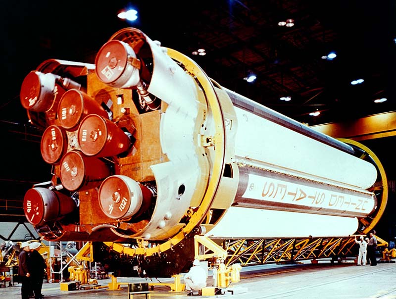
“A “full house” replaced “three-of-a-kind” at the National Aeronautics and Space Administration’s Michoud Operations this week, as a second Saturn I space vehicle first stage was returned after static firing tests at the Marshall Space Flight Center, Huntsville, Ala. Lined up (left-to-right) in assembly and checkout positions are two Saturn IB flight boosters, A Saturn IB dynamic test stage and two Saturn I first stages. The 1.5-million-pound-thrust Saturn I boosters will be used in the early phases of the Apollo manned lunar landing program as well as to orbit meteoroid technology satellites. The more powerful – 1.6-million-pound-thrust – Saturn IB first stages will launch Apollo spacecraft into earth orbit for astronaut training and spacecraft test preliminary to actual manned landings on the moon. Both the Saturn I and Saturn IB are two-stage launch vehicles. The 21-foot-diameter, 80-foot-tall first stages are being assembled at Michoud by the Chrysler Corporation Space Division.”
SA-8 first stage is on the far right.
According to this:
history.nasa.gov/MHR-5/Images/fig200.jpg
From left to right, it's: S-IB-2, S-IB-1, S-IB-D/F, and S-I-...IDK...since the online image is cutoff at this point). But hey, identification of 4 out of 5 ain't bad.
7.75" x 9.5"
A stunning COLOR photo from the same photo 'session' is at:
4.bp.blogspot.com/-TcGfrFQUWq0/TqmOPPBoh4I/AAAAAAAAB2s/QZ....
In fact, the position of the gentlemen in both photos seems to suggest they were taken near simultaneously from their respective angles.
Also:
spacerockethistory.com/wp-content/uploads/2015/03/11-Boos...
In der gesprengten V2 Raketen Triebwerksanlage.
In the burst open V2 Rocketengine facility.
Urbextour with JoniB, Bunkersachse, Marko Bunker and Bunkerpaule.
PictionID:55546770 - Catalog:14_036831 - Title:GD/Astronautics Details: Kick Stage Study Presentation - Filename:14_036831.tif - ---- Images from the Convair/General Dynamics Astronautics Atlas Negative Collection. The processing, cataloging and digitization of these images has been made possible by a generous National Historical Publications and Records grant from the National Archives and Records Administration---Please Tag these images so that the information can be permanently stored with the digital file.---Repository: San Diego Air and Space Museum
Second test firing of Zefiro-40 on 3 October 2024.
A redesigned Zefiro-40 solid rocket motor, the second stage of the Vega-C rocket, was successfully fired for the second time by prime contractor Avio at its Salto di Quirra test facility in Sardinia, Italy. This second firing follows from a first firing test of the motor in May 2024 and concludes the qualification tests for the improved engine nozzle design of the Zefiro-40.
Engineers are analysing the motor’s performance, with the initial post-test review indicating that the new nozzle assembly and the motor performed as expected.
Whereas the first test in May was performed under high operating pressure and with a short burning time, today’s test was conducted at a low operating pressure and burnt for longer, as expected and according to the test predictions. The two firings are standard procedure when preparing solid-fuel rocket motors for operations, allowing Vega-C to be launched by the end of 2024.
Zefiro-40 is a 7.6 m tall rocket motor, loaded with over 36 tonnes of solid propellant, and just one of three solid-propulsion stages that are used by Vega-C. For this test the motor was installed on its horizontal test bench. Zefiro-40 is developed and manufactured by Avio in their Colleferro factory near Rome, Italy.
Credits: Avio
“Frequently used (mistakenly) as a Saturn V translunar injection (re: "In the Shadow of the Moon") this onboard piece is actually from a Saturn IB mission, AS-202. It is shot from the interstage forward of the S-I stage, facing forward, to document the separation of the S-IVB. Since no footage exists of a trans-lunar injection (where would it be shot from?) this is our best view of what an in-flight firing of the S-IVB looks like.”
The above is from the first linked video. The frame appears to be taken from the 15/16-second mark. Gorgeous:
Credit: Pizza Marko
Two synched views, outstanding:
www.youtube.com/watch?v=PRu40PGQyTw
Credit: Retro Space HD/YouTube
Also…absolutely wonderful:
gwsbooks.blogspot.com/2015/04/camera-pods.html
Credit: Wes Oleszewski/“Growing Up With Spaceflight” website
Media and social media followers had an invitation to watch as NASA tested the RS-25 engine like those that will power the rocket that launches astronauts on missions to an asteroid and to Mars. The test took place on Thursday, August 13, at NASA’s Stennis Space Center in Mississippi.
This is an actual piece of an F-1 engine, flown on Apollo 11, and recovered from the Atlantic Ocean in 2013. Like much of the Apollo missions, how they managed to get this piece is beyond me...
This piece of hardware is the single most important element of those lunar landing missions: if it hadn’t been perfected, we could not have gone to the Moon—at least by President Kennedy’s timetable.
For the technically-minded, the larger the rocket engine, the more the combustion of liquid oxygen and fuel becomes less uniform. In the massive F-1 engine required to lift the Saturn V, this problem, known as combustion instability, is fatal to the engine. Quite a few blew up between 1959 and 1966, before the engineers at Rocketdyne fixed the problem with this version of the injector plate. It sat on the top of a barrel where the oxidizer and fuel were pumped in at very high pressure and flow rate though the little holes in the plate, then burned in the barrel, known as the combustion chamber. Initially, the plate didn’t have the baffles on them, just the holes. That made for a somewhat more powerful engine—that always blew up! By adding the baffles the design stopped blowing up, even when they put small explosive charges into the engine to try to force instability to occur.
The plate here was the result of seven years’ hard work to create an engine that would self-dampen combustion instability. Without it, no Saturn V could have successfully flown.
I bought this visor on Ebay yesterday. The visor on my 1950 Oldsmobile is the same, however, the chrome is in bad condition. This visor will save me from having to have mine repaired. I only need to re-paint this one.
Eines der 5 Raketentriebwerke "F-1 Rocketdyne" der Saturn V (Stufe 1)
National Air & Space Museum, Washington DC