View allAll Photos Tagged rocketengine
One of the main stage rocket engines of a Saturn V on display at the Air and Space Museum in Washington DC.
Watch technicians at NASA's Michoud Assembly Facility in New Orleans move the engine section of NASA's #SpaceLaunchSystem rocket for #Artemis IV after welding was completed. This hardware is the first large piece manufactured for the Artemis IV mission and makes up the lowest portion of the 212-foot-tall core stage. Currently, the team is in the process of outfitting engine sections for the Artemis II and Artemis III missions.
Image credit: NASA/Jared Lyons
#MoontoMars #NASAMarshall #nasasls #artemis #NASA #NASAMarshall #MSFC #MarshallSpaceFlightCenter #SpaceLaunchSystem #MichoudAssemblyFacility #NASAMichoud
In this image from Dec. 11, 2024, the 212-foot-tall SLS (Space Launch System) core stage is lowered into High Bay 2 at the Vehicle Assembly Building at NASA’s Kennedy Space Center in Florida. With the move to High Bay 2, NASA and Boeing technicians now have 360-degree access to the core stage both internally and externally.
The Artemis II test flight, targeted for launch in 2026, will be NASA’s first mission with crew under the Artemis campaign. NASA astronauts Victor Glover, Christina Koch, and Reid Wiseman, as well as CSA (Canadian Space Agency) astronaut Jeremy Hansen, will go on a 10-day journey around the Moon and back.
Credits: NASA/Kim Shiflett
#NASA #space #moon #NASAKennedy #NASAMarshall #msfc #sls #spacelaunchsystem #nasasls #rockets #exploration #artemis #rocketengine
On Jan. 17, NASA continued a critical test series for future flights of NASA’s SLS (Space Launch System) rocket in support of the Artemis campaign with a full-duration hot fire of the RS-25 engine on the Fred Haise Test Stand at NASA’s Stennis Space Center near Bay St. Louis, Mississippi.
Data collected from the test series will be used to certify production of new RS-25 engines by lead contractor Aerojet Rocketdyne, an L3Harris Technologies company, to help power the SLS rocket on future Artemis missions to the Moon and beyond, beginning with Artemis V.
Image credit: NASA/Danny Nowlin
#NASA #NASAMarshall #sls #spacelaunchsystem #nasasls #exploration #rocket #artemis #ssc #StennisSpaceCenter #Stennis
“Suited technicians “safe” the Orbiter Challenger after eight days in orbit and a successful landing at KSC. Cooling and purge lines are hooked up to the orbiter to prepare it for towing to the Orbiter Processing Facility for post-flight assessment. The 41G astronaut crew arrived safely at KSC’s runway at the conclusion of the mission. This was the second shuttle landing at KSC since the beginning of the STS program.”
Note the tile damage:
www.nasa.gov/feature/35-years-ago-sts-41g-a-flight-of-man...
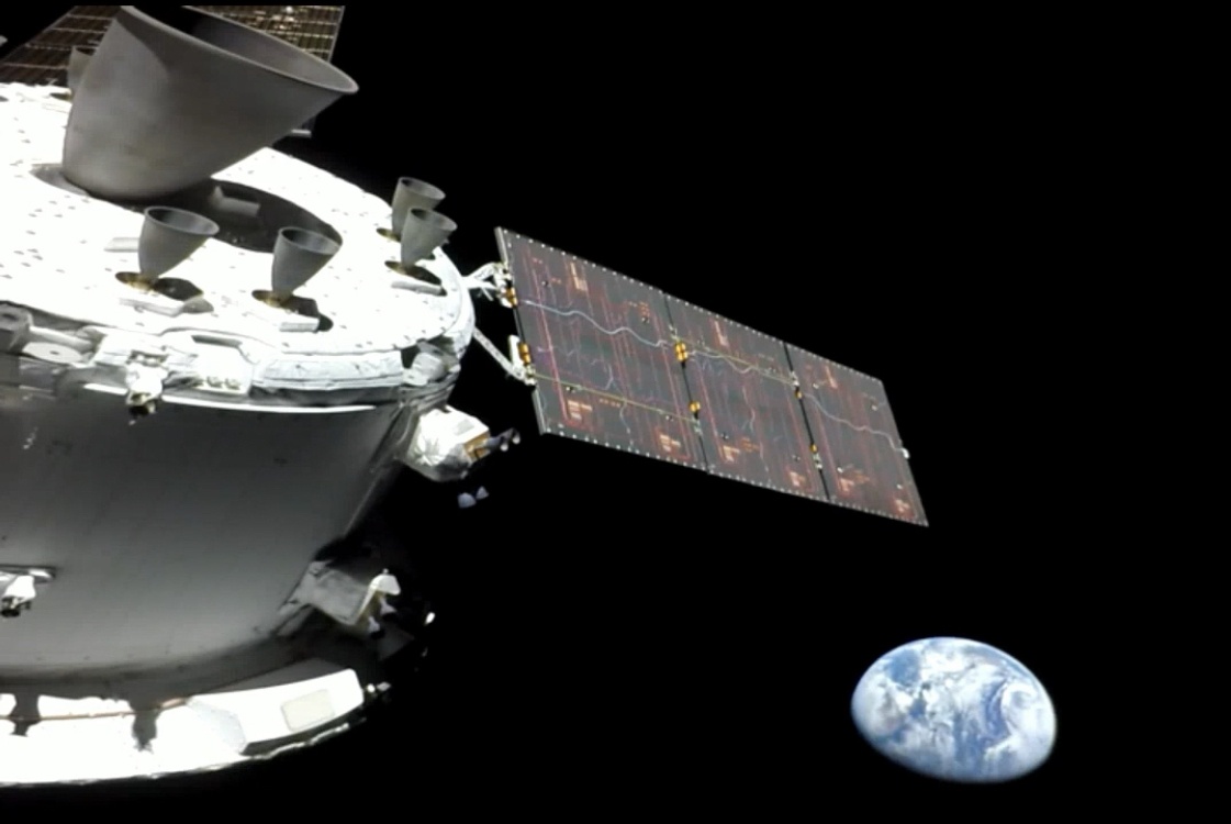
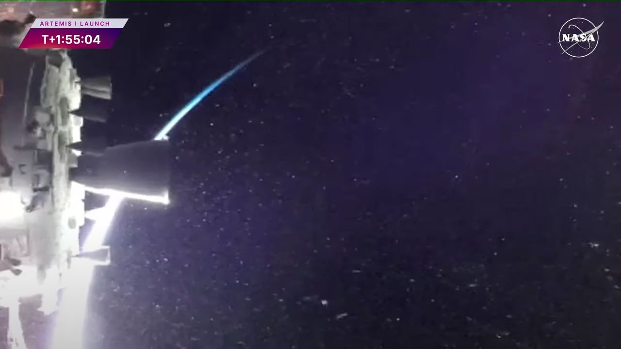
Very cool, especially since both OMS engine nozzles can be seen…the power plant of one of them being at the end of the European Service Module (ESM) of Artemis I:
mobile.twitter.com/ThePrimalDino/status/1504450964928942086
Credit: David Willis/Twitter
So, the large nozzle seen here is powered by one of the two OMS engines behind one or the other of the two nozzles visible in my posted photograph:
uploads.disquscdn.com/images/60ddeac864c868b26fed545499d5...
uploads.disquscdn.com/images/a5ed616c5381feb7ec49b0ae5640...
Both above credit: SPACE NEWS website
STS-41G being the engine's first flight, Artemis I its last.
Also:
www.aero-news.net/annticker.cfm?do=main.textpost&id=9...
Credit: Aero-News Network website
en.wikipedia.org/wiki/Space_Shuttle_recovery_convoy
Credit: Wikipedia
The solid rocket boosters for NASA's Space Launch System rocket are the largest, most powerful boosters every built for flight. As NASA and Northrop Grumman teams in Utah prepare for a Flight Support Booster (FSB-1) test of NASA's Space Launch System rocket on Sept. 2, learn more about the SLS boosters in this episode of Rocket Science in 60 Seconds with SLS booster subsystem manager and #NASAMarshall team member Julia Khodabandeh.
Image credit: NASA/Tyson Eason
#NASA #space #moon #Mars #NASAMarshall #msfc #sls #spacelaunchsystem #nasasls #rockets #exploration #engineering #explore #rocketscience #artemis #solidrocketbooster
This video shows how crews at NASA’s Marshall Space Flight Center in Huntsville, Alabama, are manufacturing and assembling the launch vehicle stage adapter (LVSA) for the second flight of NASA’s Space Launch System (SLS) rocket. The launch vehicle stage adapter in this video will be used for Artemis II, the first crewed mission of NASA’s Artemis program. The launch vehicle stage adapter is a cone-shaped piece of hardware that connects the rocket’s upper and lower stages. The LVSA is welded together as two unique cones, then stacked on top of one another. Technicians recently moved the aft cone to begin welding the LVSA at Marshall. While the larger stages of the SLS rocket are manufactured at other NASA facilities, the LVSA flight hardware is produced exclusively at Marshall by Teledyne Brown Engineering in Huntsville.
Image Credit: NASA
#NASA #space #moon #Mars #NASAMarshall #msfc #sls #spacelaunchsystem #nasasls #rockets #exploration #engineering #explore #rocketscience #artemis #LVSA #ArtemisII
TO THE READER
This book, SPACE PILOTS, is the second of a series on Adventure in Space. This series is the story of the rocket age in which Man will pierce the atmosphere and conquer the open space beyond it. This age is going to come much sooner than most people realize, and some of you who read this will take an active part in it. Here you will learn about the people who will fly the rocket ships.
Some of you may be among those who will be trained for this task. – Willy Ley
Engineers and technicians with NASA’s Exploration Ground Systems Program integrate the right forward center segment onto mobile launcher 1 inside the Vehicle Assembly Building at NASA’s Kennedy Space Center in Florida on Wednesday, Jan. 22, 2025. The boosters will help support the remaining rocket components and the Orion spacecraft during final assembly of the Artemis II Moon rocket and provide more than 75 percent of the total SLS (Space Launch System) thrust during liftoff from NASA Kennedy’s Launch Pad 39B
Credits: NASA
#NASA #space #moon #NASAKennedy #NASAMarshall #msfc #sls #spacelaunchsystem #nasasls #rockets #exploration #artemis #rocketengine #ExplorationGroundSystems #EGS #ArtemisII
All four RS-25 engines were structurally mated to the core stage for NASA's Space Launch System (SLS) rocket for Artemis I, the first mission of SLS and NASA's Orion spacecraft. To complete assembly of the rocket stage, engineers and technicians are now integrating the propulsion and electrical systems within the structure. The completed core stage with all four RS-25 engines attached is the largest rocket stage NASA has built since the Saturn V stages for the Apollo Program that first sent Americans to the Moon. The stage, which includes two huge propellant tanks, provides more than 2 million pounds of thrust to send Artemis I to the Moon. Engineers and technicians at NASA's Michoud Assembly Facility in New Orleans attached the fourth RS-25 engine to the rocket stage Nov. 6 just one day after structurally mating the third engine. The first two RS-25 engines were structurally mated to the stage in October. After assembly is complete, crews will conduct an integrated functional test of flight computers, avionics and electrical systems that run throughout the 212-foot-tall core stage in preparation for its completion later this year. This testing is the first time all the flight avionics systems will be tested together to ensure the systems communicate with each other and will perform properly to control the rocket's flight. Integration of the RS-25 engines to the massive core stage is a collaborative, multistep process for NASA and its partners Boeing, the core stage lead contractor, and Aerojet Rocketdyne, the RS-25 engines lead contractor.
Image credit: NASA/Eric Bordelon
A Space Launch System (SLS) rocket small-scale solid rocket booster roared to life during a 22-second test on Aug. 6 at NASA’s Marshall Space Flight Center in Huntsville, Alabama. The test with a 24-inch booster will help engineers evaluate a new material for booster nozzle cleaning that may be used on future SLS rocket boosters.
Image credit: NASA/Tyson Eason
Over the course of her long career, Ethel Bauer made instrumental contributions to several NASA programs ranging from humanity’s first steps on the lunar surface to using satellite data to increase crop yields in agriculture, along with technology transfers in climate, and communications. Ethel’s was certainly a career spent breaking barriers and bringing others along with her. This image shows Ethel Bauer working on trajectories at NASA’s Marshall Space Flight Center in 1965.
Image credit: NASA
NASA and industry partners Aerojet Rocketdyne and Boeing have installed all four RS-25 engines onto the SLS (Space Launch System) rocket core stage for the agency’s Artemis II mission, signaling the core stage is nearing completion. Once complete, the core stage will be shipped to NASA’s Kennedy Space Center in Florida. During launch, the rocket’s engines provide more than two million pounds of combined thrust.
Image credit: NASA/Danny Nowlin
#NASA #NASAMarshall #NASAStennis #sls #spacelaunchsystem #nasasls #exploration #rocket #artemis #moontomars
Space Launch System Core Stage Engine
The RS-25 engine, which successfully powered the space shuttle, is being modified for America's next great rocket, the Space Launch System. Hot-fire testing for the engine will begin in early 2015.
Image Credit: NASA/Stennis
Read more about the RS-25 Engine Test:
www.nasa.gov/sls/smat-acoustic-testing.html
Image credit: NASA/Stennis
More about SLS:
www.nasa.gov/sls/core-stage-engine.html
More SLS Photos:
www.nasa.gov/exploration/systems/sls/multimedia/gallery/S...
Space Launch System Flickr album
www.flickr.com/photos/28634332@N05/sets/72157627559536895/
_______________________________
These official NASA photographs are being made available for publication by news organizations and/or for personal use printing by the subject(s) of the photographs. The photographs may not be used in materials, advertisements, products, or promotions that in any way suggest approval or endorsement by NASA. All Images used must be credited. For information on usage rights please visit: www.nasa.gov/audience/formedia/features/MP_Photo_Guidelin...
All the major structures that will form the core stage for NASA’s SLS (Space Launch System) rocket for the agency’s Artemis III mission are structurally complete. Technicians finished welding the 51-foot liquid oxygen tank structure, left, inside the Vertical Assembly Building at NASA’s Michoud Assembly Facility in New Orleans Jan. 8. The liquid hydrogen tank, right, completed internal cleaning Nov. 14.
Image credits: NASA/Michael DeMocker
#NASA #space #moon #NASAMichoud #NASAMarshall #msfc #sls #spacelaunchsystem #nasasls #rockets #exploration #artemis #rocketengine
#480
Spuren der ehemaligen V2 Rüstungsproduktion.
Traces of the V2 Rocketengine facility.
Urbextour with JoniB, Bunkersachse, Marko Bunker and Bunkerpaule.
Engineers and technicians at NASA's Michoud Assembly Facility in New Orleans have structurally mated the first of four RS-25 engines to the core stage for NASA's Space Launch System (SLS) rocket that will help power the first Artemis mission to the Moon. Integration of the RS-25 engines to the recently completed core stage structure is a collaborative, multistep process for NASA and its partners Boeing, the core stage lead contractor, and Aerojet Rocketdyne, the RS-25 engines lead contractor. To complete the installation, the technicians will now integrate the propulsion and electrical systems. The installation process will be repeated for each of the four RS-25 engines. The four RS-25 engines used for Artemis I were delivered to Michoud from Aerojet Rocketdyne's facility at NASA's Stennis Space Center near Bay St. Louis, Mississippi, in June. The engines, located at the bottom of the core stage in a square pattern, are fueled by liquid hydrogen and liquid oxygen. During launch and flight, the four engines will fire nonstop for 8.5 minutes, emitting hot gases from each nozzle 13 times faster than the speed of sound. The completed core stage with all four engines attached will be the largest rocket stage NASA has built since the Saturn V stages for the Apollo Program.
NASA is working to land the first woman and next man on the Moon by 2024. SLS is part of NASA's backbone for deep space exploration, along with Orion and the Gateway in orbit around the Moon. SLS is the only rocket that can send Orion, astronauts and supplies to the Moon on a single mission.
Image credit: NASA
Just kidding, this is part of a dismantled grain elevator that is being disassembled on Smith Hatchery Road in Boone County Missouri. They are probably gonna build some condos here or new housing development.
NASA will begin a new RS-25 test series Oct. 5, the final round of certification testing ahead of production of an updated set of the engines for the SLS (Space Launch System) rocket. The engines will help power future Artemis missions to the Moon and beyond.
A series of 12 tests stretching into 2024 is scheduled to occur on the Fred Haise Test Stand at NASA’s Stennis Space Center near Bay St. Louis, Mississippi. The tests are a key step for lead SLS engines contractor Aerojet Rocketdyne, an L3Harris Technologies company, to produce engines that will help power the SLS rocket, beginning with Artemis V.
In this image, crews bring RS-25 developmental engine E0525 to the Fred Haise Test Stand at NASA’s Stennis Space Center on Aug. 30 for the upcoming certification test series. The first test of the 12-test series is Thursday, Oct. 5 at NASA Stennis.
Image credit: NASA/Danny Nowlin
#NASA #NASAMarshall #NASAStennis #sls #spacelaunchsystem #nasasls #exploration #rocket #artemis #moontomars
This week in 1966, NASA’s Marshall Space Flight Center successfully static-fired S-IC-2, the first stage of the second Saturn V flight vehicle. The stage was powered by five F-1 engines, each capable of producing 1.5 million pounds of thrust. The S-IC-2 was one of the first two flight models of the S-IC stage and was used on the Apollo 6 mission. Here, the S-IC-T, a static firing test stage, is installed and awaits the first firing of all five F-1 engines at the Marshall static test stand. Now through December 2022, NASA will mark the 50th anniversary of the Apollo Program that landed a dozen astronauts on the Moon between July 1969 and December 1972, and the first U.S. crewed mission -- Apollo 8 -- that circumnavigated the Moon in December 1968. The NASA History Program is responsible for generating, disseminating and preserving NASA's remarkable history and providing a comprehensive understanding of the institutional, cultural, social, political, economic, technological and scientific aspects of NASA 's activities in aeronautics and space. For more pictures like this one and to connect to NASA's history, visit the Marshall History Program's webpage.
Image credit: NASA
Engineers at Orbital ATK in Promontory, Utah, prepare to test the booster that will help power NASA’s Space Launch System to space to begin missions to deep space, including to an asteroid and Mars. A test on March 11 is one of two that will qualify the booster for flight.
Image Credit: Orbital ATK
Read Full Advisory on Booster Test: www.nasa.gov/press/2015/march/nasa-television-to-air-majo...
More about SLS:
www.nasa.gov/exploration/systems/sls/index.html
More SLS Photos:
www.nasa.gov/exploration/systems/sls/multimedia/gallery/S...
Space Launch System Flickr photoset:
www.flickr.com/photos/28634332@N05/sets/72157627559536895/
_______________________________
These official NASA photographs are being made available for publication by news organizations and/or for personal use printing by the subject(s) of the photographs. The photographs may not be used in materials, advertisements, products, or promotions that in any way suggest approval or endorsement by NASA. All Images used must be credited. For information on usage rights please visit: www.nasa.gov/audience/formedia/features/MP_Photo_Guidelin...
In the fall of 2023, NASA hot fire tested an aluminum-based, 3D-printed rocket engine nozzle. What made the event remarkable is that aluminum isn’t typically used for additive manufacturing because the process causes it to crack, and it isn’t used in rocket engines due to its low melting point. Yet the test was a success.
The new possibility of printed aluminum engine parts will mean significant savings for NASA in terms of time, money, and, most importantly, the weight of future spacecraft. And Elementum 3D Inc., a partner on the project, is now bringing the benefits of that technology to its customers, including not only rocket engine manufacturers but also makers of race cars, lighting fixtures, computer chips, and more
In this image, a laser powder directed energy deposition (LP-DED) 3D printer at RPM Innovations’ facility additively manufactures a large-scale aerospike rocket engine nozzle from one of Elementum 3D’s specialized, 3D-printable aluminum alloys.
Image credit: RPM Innovations Inc.
#NASAMarshall #NASA #3dprinting #RocketEngine
SLS Booster Work Continues after Major Test
Orbital ATK technicians detach the center forward segment from the forward segment of NASA's five-segment booster that fired up for testing March 11 at Orbital ATK's test facility in Promontory, Utah. The two-minute static test was the first of two ground tests to support qualification of the boosters that will help launch the first flight of NASA's new rocket--the Space Launch System (SLS). The most powerful launch vehicle ever built, SLS will take humans and cargo on deep space missions, including an asteroid and ultimately to Mars. Disassembly and inspection of the booster is ongoing, but preliminary analysis of the test data shows all test objectives were successfully completed during the hot fire. The second qualification test is planned for early 2016. Once qualified, flight booster hardware will undergo final manufacturing and preparation for shipment to NASA’s Kennedy Space Center in Florida for the rocket's first unmanned flight.
Image credit: Orbital ATK
PictionID:53756991 - Catalog:14_031503 - Title:GD/Astronautics Details: Site S-2; Static Test on 2D; Inside B-1 Thrust Chamber Date: 05/25/1959 - Filename:14_031503.tif - Images from the Convair/General Dynamics Astronautics Atlas Negative Collection. The processing, cataloging and digitization of these images has been made possible by a generous National Historical Publications and Records grant from the National Archives and Records Administration---Please Tag these images so that the information can be permanently stored with the digital file.---Repository: San Diego Air and Space Museum
Further reinforcing my perpetual confusion of space shuttle concept identifications during the late 60’s - mid 70’s, there’s this.
I’m pretty sure this design is referred to as “MSC 040A”. Possibly during/under Phase-B’? - with not two, not three, but 4, count ‘em, FOUR main engines - AND bulging ‘canopy’.
Who knew?!
As if that wasn’t enough, I think subsequent(?) to this, design “MSC 042A“ featured ZERO main engines…sort of a pre-Buran Buran design. And, get this, riding atop an uprated Titan IIIL-6 (apparently with 6 strap-on SRBs).
I don’t even know what that is!
The information is out there, to a degree, in bits & pieces & all over the place. Unfortunately, it’s inducing exponentially increasing ass-pain finding/confirming accurate information.
Fortunately, in this instance:
“…Though the issue of payload size and weight was still open, the basic design of the orbiter was approaching a definitive form. During the fall of 1971, when the Mark I/Mark II approach was still in the forefront, the contractors had worked from a Max Faget configuration known as MSC-040A. It elaborated the earlier MSC-040 by adding small liquid-fuel engines for orbital maneuvers, along with thrusters for attitude control that were mounted at the tips of the wings and tail.
The Mark I/Mark II concept, however, with its phased technology, had never been more than an artificial stratagem to reduce peak funding by stretching out the development, while accepting serious compromises in design. With Shultz’s support, NASA now was free to build an honest orbiter, one that would be right the first time. MSC-040A had called for four J-2S engines; a variant of January 1972, MSC-040C, replaced them with three SSMEs…”
At:
history.nasa.gov/SP-4221/ch9.htm
Also, always excellent:
www.capcomespace.net/dossiers/espace_US/shuttle/index.htm
Specifically:
mirrors.josefsipek.net/www.capcomespace.net/dossiers/espa...
Credit: CAPCOM ESPACE website (mirror)
Finally, what’s most important, a beautiful work, unfortunately by an unidentified artist, wonderfully exemplifying the evolution of designs, as evidenced below. In this, I’m amused not only by the slightly undersized nozzle of the upper right engine, but also the detail of the aft bulkhead/base heat shield, where the engines are attached…nice.
UPDATE: Based on another work from this 'series', I believe this to be the work of Norman Tiller.
An excellent photograph, ca. 1966/67 of the assembly line for F-1 rocket engine thrust chambers at North American Aviation’s Rocketdyne Division facility, Canoga Park, CA.
The number on the dolly is that of the engine on it, in this case '2093' being visible.
And along those lines...excellent...as always:
heroicrelics.org/info/f-1/f-1-serials.html
Credit: Mike Jetzer/HEROIC RELICS website
Wouldn't it be cool to know if '2093' helped to power any flight? And if so, which?
Note that the caged overhead red light of Engine no. 2093’s bay & that of the bay next to it are both on. Price check?
Probably too simplistic an observation; however, based on the positioning of the two crouched individuals (in the immediate vicinity of hydraulic jack stands), and the gentleman standing between them, staring at a level placed on the dolly frame, they appear to be ensuring the thrust structure is level. And five other guys…that’s a lot of oversight…for a leveling procedure. Finally, pushing the trivial ‘pursuit’ of my inane observations, note also the different color (red & black) of the Rocketdyne logos on the lab coats of the two gentlemen immediately to the left of the support column. Denoting hierarchy, different sections, departments, etc? And one of them wearing a bowtie, with clipboard, thick documentation of some sort & pencil at the ready…so maybe an inspector or someone supervisory? Not to stereotype, but (to me) a bowtie is an indicator of some eclectic, quirky & slightly eccentric thing going on. So, maybe he’s like a supervisor from the theoretical/future propulsion technologies development section/department. You know, something really heady & ‘out there’.
A contemporary ‘official’ caption associated with a similar image:
“F-1 Assembly – Archive photo of the F-1 assembly line at Aerojet Rocketdyne’s Canoga Park, California facility.”
At:
www.rocket.com/sites/default/files/images/media/apollo50/...
Credit: Aerojet Rocketdyne website
Good Saturn engine reading:
TO THE READER
This book, MAN-MADE SATELLITES, is the first of a series on Adventure in Space. This series is the story of the rocket age in which Man will pierce the atmosphere and conquer the open space beyond it. This age is going to come much sooner than most people realize.
We hope that this series will be the key that opens the door to the rocket age for you. – Willy Ley
Engineers and technicians at NASA’s Michoud Assembly Facility in New Orleans have attached all four RS-25 engines to the core stage for NASA’s Space Launch System (SLS) rocket that will help power the first Artemis mission to the Moon. To complete assembly of the rocket stage, crews are now integrating the propulsion and electrical systems within the structure. The completed core stage with all four RS-25 engines attached is the largest rocket stage NASA has built since the Saturn V stages for the Apollo Program that first sent Americans to the Moon. Engineers and technicians at Michoud attached the fourth RS-25 engine to the rocket stage Nov. 6 just one day after structurally mating the third engine. The first two RS-25 engines were structurally mated to the stage in October. Integration of the RS-25 engines to the recently attached engine section is a collaborative, multistep process for NASA and its partners Boeing, the core stage lead contractor, and Aerojet Rocketdyne, the RS-25 engines lead contractor. The four RS-25 engines, which are each roughly the size of a compact car, will together provide the SLS rocket 2 million of its 8.8 million pounds of maximum thrust. For more information about SLS, visit https://www.nasa.gov/sls.
Image credit: NASA
A truly amazing inboard profile/cutaway view of a complete space shuttle stack, ca. 1983.
An earlier version, understandably less precise, detailed or refined, prior to the flight of STS-1, can be seen at the following:
www.youtube.com/watch?v=XuldqDPk3mE
Credit: AIRBOYD/YouTube (AIRBOYD having many excellent videos of a variety of aerospace/rocketry footage btw)
The gracious generosity of Angela Carole Brown revealed this - in my estimation – masterpiece, to be by the hand of her father, Ted Brown, as I’m sure the precursor is as well.
Commencing at the 1:33 mark. A beautiful & touching remembrance/memorial:
www.youtube.com/watch?v=D-w4MHqTx5A
Credit: Angela Carole Brown/YouTube
Click on the “Ted Brown” tag & prepare to be blown away.
The only other place it appears to be available is one of the pay-to-play sites, which I won't dignify with its link.
NASA conducted the first hot fire of a new RS-25 test series Oct. 17, beginning the final round of certification testing ahead of production of an updated set of the engines for the SLS (Space Launch System) rocket. The engines will help power future Artemis missions to the Moon and beyond.
Operators fired the RS-25 engine for more than nine minutes (550 seconds), longer than the 500 seconds engines must fire during an actual mission, on the Fred Haise Test Stand at NASA’s Stennis Space Center, near Bay St. Louis, Mississippi. Operators also fired the engine up to the 111% power level needed during an SLS launch. The hot fire marked the first in a series of 12 tests scheduled to stretch into 2024. The tests are a key step for lead SLS engines contractor Aerojet Rocketdyne, an L3Harris Technologies company, to produce engines that will help power the SLS rocket, beginning with Artemis V.
Image credit: NASA
#NASA #NASAMarshall #sls #spacelaunchsystem #nasasls #exploration #rocket #artemis #ssc #StennisSpaceCenter #Stennis
Last week, NASA's Exploration Ground Systems team transported the forward assemblies of NASA's SLS (Space Launch System) solid rocket boosters in preparation for the Artemis II mission. These are the final pieces of the boosters to stack on mobile launcher 1 and will signify the completion of booster assembly at NASA's Kennedy Space Center.
Credits: NASA
#NASA #space #moon #NASAKennedy #NASAMarshall #msfc #sls #spacelaunchsystem #nasasls #rockets #exploration #artemis #rocketengine #ExplorationGroundSystems #EGS #ArtemisII
An impressive photograph, ca. 1966/67 of the assembly line for F-1 rocket engine thrust chambers at North American Aviation’s Rocketdyne Division facility, Canoga Park, CA.
The number on the dolly is that of the engine on it, in this case '2053' & '2057' being visible.
And along those lines...excellent...as always:
heroicrelics.org/info/f-1/f-1-serials.html
Credit: Mike Jetzer/HEROIC RELICS website
The contemporary ‘official’ caption associated with the image:
“F-1 Assembly – Archive photo of the F-1 assembly line at Aerojet Rocketdyne’s Canoga Park, California facility.”
At:
www.rocket.com/sites/default/files/images/media/apollo50/...
Credit: Aerojet Rocketdyne website
Good Saturn engine reading:
“During Apollo 4, the Service Module main engine was used to accelerate the unmanned spacecraft so that its reentry velocity would be comparable to that at the end of a manned lunar mission.”
The above, I assume, is per the caption/accompanying press slug associated with the linked photo below.
Although unnumbered, the work is clearly by Russ Arasmith. As such, it was likely used in press releases & therefore, handled accordingly. Despite this, it has retained its high gloss.
The QM-1 test just completed. smile emoticon
#JourneytoMars #SLSFiredUp
More about SLS:
www.nasa.gov/exploration/systems/sls/index.html
More SLS Photos:
www.nasa.gov/exploration/systems/sls/multimedia/gallery/S...
Space Launch System Flickr photoset:
www.flickr.com/photos/28634332@N05/sets/72157627559536895/
_______________________________
These official NASA photographs are being made available for publication by news organizations and/or for personal use printing by the subject(s) of the photographs. The photographs may not be used in materials, advertisements, products, or promotions that in any way suggest approval or endorsement by NASA. All Images used must be credited. For information on usage rights please visit: www.nasa.gov/audience/formedia/features/MP_Photo_Guidelin...
The RS-25 engine fires up for a 500-second test Jan. 9 at NASA's Stennis Space Center near Bay St. Louis, Mississippi. This is the first of eight tests for the development engine, which will provide NASA engineers with critical data on the engine controller unit and inlet pressure conditions.
Image credit: NASA
Read News Release:
www.nasa.gov/press/2015/january/rs-25-engine-testing-blazes-forward-for-nasas-space-launch-system/
More about SLS:
www.nasa.gov/exploration/systems/sls/index.html
More SLS Photos:
www.nasa.gov/exploration/systems/sls/multimedia/gallery/S...
Space Launch System Flickr album
www.flickr.com/photos/28634332@N05/sets/72157627559536895/
______________________________
These official NASA photographs are being made available for publication by news organizations and/or for personal use printing by the subject(s) of the photographs. The photographs may not be used in materials, advertisements, products, or promotions that in any way suggest approval or endorsement by NASA. All Images used must be credited. For information on usage rights please visit: www.nasa.gov/audience/formedia/features/MP_Photo_Guidelin...
NASA completed the sixth of 12 scheduled RS-25 engine certification tests in a critical series for future flights of the agency’s SLS (Space Launch System) rocket as engineers conducted a full-duration hot fire Jan. 27 at NASA’s Stennis Space Center near Bay St. Louis, Mississippi.
The current series builds on previous hot fire testing conducted at NASA Stennis to help certify production of new RS-25 engines by lead contractor Aerojet Rocketdyne, an L3 Harris Technologies company. The new engines will help power NASA’s SLS rocket on future Artemis missions to the Moon and beyond, beginning with Artemis V.
Image credit: NASA/Danny Nowlin
#NASA #NASAMarshall #sls #spacelaunchsystem #nasasls #exploration #rocket #artemis #ssc #NASAStennis
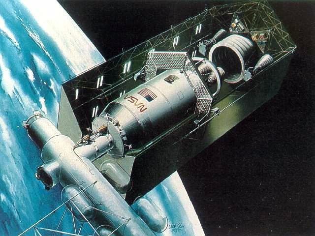
“This artist concept shows an Orbital Transfer Vehicle (OTV) being serviced in the hangar of a Space Station located in low Earth orbit. The hangar serves as a shelter to protect the upper stage spacecraft from space debris and as a maintenance facility between spaceflights. Lighting and easy accessibility are provided for repair and servicing operations. The OTV would be based at the Space Station semi-permanently to allow more flexibility in payload handling and launching. This spacecraft could take up to 10 tons of cargo or people thousands of miles into space and be able to return to its launch orbit for reuse. Boeing Aerospace Company is conducting concept definition studies of the OTV for NASA’s Marshall Space Flight Center in Huntsville, Alabama.”
Looks like the engines of the OTV are going to be changed out. Or, at the very least, the SOC appears to be capable of/equipped to do so.
And/or:
“SOC OTV - 1982
Space Tug / Space Operations Center, 1982. NASA/Johnson also regarded the space tug as an integral component of its Space Operations Center plan. This Boeing illustration from 1982 depicts a space tug being serviced inside its hangar onboard SOC.
Credit: NASA via Marcus Lindroos”
The above & image (in color) at/from:
www.astronautix.com/o/otv.html
Specifically:
www.astronautix.com/graphics/s/soc82otv.jpg
And:
www.pmview.com/spaceodysseytwo/station/sld006.htm
Credit: PMView Pro website
Yet another testament to John J. Olson’s talent…the attention to detail, shading, perspective, etc., etc.
8.375” x 11”.
Kiwi-A Prime is one of a series of atomic reactors for studying the feasibility of nuclear rocket propulsion, in Los Alamos, New Mexico. Developed by the Los Alamos Scientific Laboratory for the U.S. Atomic Energy Commission, the reactor underwent a highly successful full-power run on July 8, 1960, at Nevada Test Site in Jackass Flats, Nevada. Kiwi was a project under the National Nuclear Rocket development program, sponsored jointly by Atomic Energy Commission and NASA as part of project Rover/NERVA (Nuclear Engine for Rocket Vehicle Application). The main objective of Rover/NERVA was to design a flight rated thermodynamic nuclear rocket engine. Kiwi was a prototype for a nuclear rocket reactor that could be used in space travel. Gaseous hydrogen was used as a propellant on the Kiwi-A tests that began in 1959. Kiwi-A served as a learning tool to test specifications and to discover changes that needed to be implemented in the next phase of study, the Kiwi-B series. This project began in December 1961 and used liquid hydrogen as a propellant. In the late 1960's and early 1970's, the Nixon Administration cut NASA and NERVA funding dramatically. The cutbacks were made in response to a lack of public interest in human spaceflight, the end of the space race after the Apollo Moon landing, and the growing use of low-cost unmanned, robotic space probes. Eventually NERVA lost its funding, and the project ended in 1973.
Credit: NASA
Image Number: GPN-2002-000141
Date: November 30, 1959
Steve Jurvetson of Future Ventures has a big space collection at his venture capital office. It more than doubled in size since our last video in October 2019. In this video Steve explains the space artifacts he acquired to my son Alexis. Amazing stuff, thank you Steve for the private tour on 2021-03-29! Watch the video at bit.ly/3wt0MtW
Steve, my son Alexis and I frequently hang out at Snow Ranch and at the Black Rock Desert in Nevada to launch high power rockets. Some rockets fly higher than commercial aircrafts, and sometimes they crash with a big bada boom!
I processed a realistic HDR photo from a screen grab exposure, and carefully adjusted the color balance and curves. I welcome and appreciate constructive comments.
Thank you for visiting - ♡ with gratitude! Fave if you like it, add comments below, like the Facebook page, order beautiful HDR prints at qualityHDR.com.
-- 28 mm, 1/60 sec, ISO 1000, Sony A7 II, FE 28-70mm F3.5-5.6 OSS, HDR, 1 screen grab exposures, stevej-museum-opening-full_hdr1rea1pho1a.jpg
-- CC BY-NC-SA 4.0, © Peter Thoeny, Quality HDR Photography
______________________________________________
The following text is from Steve Jurvetson's post at flic.kr/p/2kRd3pq:
The 2021 Future Ventures Space Artifact Tour
Since COVID has curtailed the in-person foot traffic, my rocket buddies Peter & Alexis Thoeny came by to shoot a whirlwind tour on video. We focus on some of the newer and topical items: flown artifacts from SpaceX and the earlier Mars programs and a lot of stuff that has been to the moon and back. I clearly get excited about the stories behind these heroic machines. Enjoy!
Some topics covered:
- 1:45 Apollo LM, X-15 and Astra engines
- 2:57 Salyut tank that crashed into Argentina
- 4:00 Apollo LM Ascent Engine valve assembly and Neil Armstrong’s nightmares
- 4:58 The Lunar Orbiter room — film lab in space
- 6:55 Observation platform from Soviet Almaz – a military space station with machine gun!
- 9:10 Soviet Buran panel and air scrubber
- 10:00 Apollo AS202 flown sextant
- 10:25 Soviet Luna 9 Anchor Petal
- 11:55 Viking Scientific Payload to detect life on Mars
- 15:30 Mars rock with trapped Martian air
- 16:49 Flown heat shields from Apollo and Gemini
- 18:20 Apollo Mission Control Deck
- 18:40 Flown Mercury Sigma-7 Logoed Panel
- 19:45 Wally Shirra’s flown Hasseblad Camera
- 21:20 Communications Headset used during the first Lunar Rover drive on the moon
- 22:20 “Apollo 14 Docking Ring”
- 24:20 Apollo CM Hatch
- 24:55 Flown Soyuz Instrument Panel
- 25:25 Flown Soviet Voskhod Spacecraft Hatch
- 26:35 Complete RL-10 Engine
- 27:00 Complete Apollo LM-2 Flight Computer
- 27:35 Apollo 17 LM Arm Rest for landing while standing, Apollo 13 uneaten meal, Buzz Aldrin’s EVA-flown flashlight
- 28:26 Apollo 16 LM COAS (heads up display)
- 29:10 John Young’s Cuff Checklist on his wrist during his lunar jump salute
- 29:55 Huge Slice of Moon Rock
- 31:10 the oldest volcanic rock, older than Earth itself.
- 33:30 Flown Aerocover from SpaceX F9R explosion
- 34:40 Planet Dove Satellite that survived the huge Antares Launch Explosion
- 36:00 Prototype build of the Apollo 11 flag,
- 37:15 The Lunar Rover room (Apollo 15 and 17 rover maps and Apollo 17 scissors)
- 38:26 Goddard rocket artifacts from 1926
- 38:50 Apollo 11 Command Module EVA handle and Buzz Aldrin’s lunar under-glove
- 40:30 Mercury Space Suit
- 40:40 SpaceX Flown DM-2 Hatch (first human flight)
- 41:45 Skylab Exercise Bike
- 43:18 Apollo LM Main Landing Leg
- 44:13 Engineering Design Notes for Apollo 11 LM
- 45:50 SpaceX SN8 Starship Test Flight Wreckage
- 47:35 Apollo CM Couch with Hand Controllers
And here are my Flickr posts on many of the artifacts seen in the video: flic.kr/s/aHsjqbz5C9
A wonderful depiction of what look like ‘fighter’ spaceplanes rounding the limb of Mars. Patrolling? Setting up for a photon bombing/laser strafing run? In pursuit of Cosmos 9309? Scrambling to intercept an alien intruder? Although, if any of the above, I would’ve expected the USAF roundel to be prominent on the vehicles.
Although the overall popular design of the spacecraft was oft-depicted, I’ve not been able to find this anywhere. It also looks like it might’ve been destined to grace the cover of one of the popular ‘space age’ magazines of the mid/late 1950s - early 1960s, or possibly a sci-fi novel of the time. The precisely marked outline along the periphery of the image, with the fiducial markings, makes me consider – and I’m talking out my ass right now – that this may’ve been the proof photo used for one of the aforementioned.
The verso bears the repeating letters/logo of "EKC". This Eastman Kodak Company backprint technique pre-dates the vintage & coveted "A KODAK PAPER" watermark. which also supports my date range guess.
Finally & thankfully, the artist’s signature is present. So, regardless of what this is, it’s a WIN - Thomas Albin. As a bonus and against the odds, there’s a single reference to him, well written/articulated, at:
www.worthpoint.com/worthopedia/thomas-albin-aviation-prin...
Credit: WorthPoint website
Indirectly, the above also supports the date range and raises the possibility that this may have been on behalf of the Martin Company.
And check this out, this shameless SOB has gone apeshit with a bunch of photos I’ve posted and/or linked to in my postings:
www.redbubble.com/i/photographic-print/Spaceplanes-Patrol...
The T-Tower or Static Test Stand at NASA Marshall Space Flight Center, Huntsville, AL was built in the mid-1950s as a missle test stand and later used in the testing of Saturn 1B rockets for the Apollo program, and Solid Rocket Boosters for the Space Shuttle. It is now decomissioned but has a listing in the National Register of Historic Places.
The RS-25 engine fires up for a 500-second test Jan. 9 at NASA's Stennis Space Center near Bay St. Louis, Mississippi. This is the first of eight tests for the development engine, which will provide NASA engineers with critical data on the engine controller unit and inlet pressure conditions.
Image credit: NASA
Read News Release:
www.nasa.gov/press/2015/january/rs-25-engine-testing-blazes-forward-for-nasas-space-launch-system/
More about SLS:
www.nasa.gov/exploration/systems/sls/index.html
More SLS Photos:
www.nasa.gov/exploration/systems/sls/multimedia/gallery/S...
Space Launch System Flickr album
www.flickr.com/photos/28634332@N05/sets/72157627559536895/
______________________________
These official NASA photographs are being made available for publication by news organizations and/or for personal use printing by the subject(s) of the photographs. The photographs may not be used in materials, advertisements, products, or promotions that in any way suggest approval or endorsement by NASA. All Images used must be credited. For information on usage rights please visit: www.nasa.gov/audience/formedia/features/MP_Photo_Guidelin...
An unknown contractor's & unknown artist’s concept, ca. 1961-64, of an Early Manned Planetary-Interplanetary Roundtrip Expedition (EMPIRE) vehicle IVO Mars.
The similarity of the vehicle and its perspective, to a similar color image (which I thought I’d linked to, but apparently NOT) originally led me to consider this to be a Convair-General Dynamics Astronautics concept. If so, possibly by the hand of John Sentovic. However, those are not Sentovic stars and the alphanumeric photo ID is representative of Boeing Co. origin. I think. Maybe. Whatever…right?
A close-up view from the test stand.
Image credit: NASA
Read News Release:
www.nasa.gov/press/2015/january/rs-25-engine-testing-blazes-forward-for-nasas-space-launch-system/
More about SLS:
www.nasa.gov/exploration/systems/sls/index.html
More SLS Photos:
www.nasa.gov/exploration/systems/sls/multimedia/gallery/S...
Space Launch System Flickr album
www.flickr.com/photos/28634332@N05/sets/72157627559536895/
______________________________
These official NASA photographs are being made available for publication by news organizations and/or for personal use printing by the subject(s) of the photographs. The photographs may not be used in materials, advertisements, products, or promotions that in any way suggest approval or endorsement by NASA. All Images used must be credited. For information on usage rights please visit: www.nasa.gov/audience/formedia/features/MP_Photo_Guidelin...
A welder at NASA’s Stennis Space Center works on a portion of piping to be installed on the A-1 Test Stand for RS-25 rocket engine testing. NASA is scheduled to begin testing RS-25 engines next spring for use on its new Space Launch System.
Image credit: NASA/MSFC
Read more:
www.nasa.gov/exploration/systems/sls/sls-engine-testing-s...
Original image:
www.nasa.gov/exploration/systems/sls/multimedia/gallery/a...
More about SLS:
www.nasa.gov/exploration/systems/sls/index.html
More SLS Photos:
www.nasa.gov/exploration/systems/sls/multimedia/gallery/S...
Space Launch System Flickr photoset:
www.flickr.com/photos/28634332@N05/sets/72157627559536895/
_____________________________________________
These official NASA photographs are being made available for publication by news organizations and/or for personal use printing by the subject(s) of the photographs. The photographs may not be used in materials, advertisements, products, or promotions that in any way suggest approval or endorsement by NASA. All Images used must be credited. For information on usage rights please visit: www.nasa.gov/audience/formedia/features/MP_Photo_Guidelin...
“Top of 31-foot-long diffusers fit around Saturn S-IV engine nozzle bells in static test stand at the Douglas Aircraft Company’s Sacramento installation. Prior to ignition of engines, air is evacuated from diffusers, simulating the near-vacuum conditions in which S-IV engines will be ignited in outer space. Douglas Missile & Space Systems technician is working on one of six RL-10A3 engines suspended from battleship tank. First static firing will occur shortly.”
If, like me, you’ve tossed & turned many-a-night wondering how in/on the world (literally) do you realistically test fire a rocket engine that’s designed to operate exclusively in a near vacuum/vacuum, and the above merely whets your appetite, we’re in luck thanks to the following:
Douglas Missile & Space Systems Division’s “ALTITUDE SIMULATION IN SATURN SIV STAGE TESTING/Douglas Paper 3172”, at:
libarchstor2.uah.edu/digitalcollections/files/original/20...
Credit: UAH Archives and Special Collections/Digital Collections website
We have:
“ABSTRACT
Altitude Simulation in Saturn SIV Stage Testing
The Douglas Aircraft Company has been involved in testing the Saturn SIV stage at the Sacramento Test Center for the past two years. The propulsion system for the SIV stage consists of six (6) Pratt & Whitney Aircraft Company rocket engines which are designed specifically for high altitude start and operation. During static firing tests of this engine at sea level, a steam jet ejector in combination with a diffuser, are used to simulate altitude conditions. The intent of this paper is to examine the performance of this altitude simulation system, and to discuss problems encountered in making it operational.
--------------------
The Douglas Aircraft Company has been involved in testing the Saturn SIV stage at the Sacramento Test Center for the past two years. The SIV is an upper stage of the National Aeronautics and Space Administration's Saturn Space Vehicle. A later version of the Saturn Space Vehicle is programmed to launch an Apollo to the moon. The propulsion system for the SIV stage consists of six (6) Pratt & Whitney Aircraft Company RLIOA-3 rocket engines capable of generating a total of 90,000 pounds thrust at altitude. These engines were designed specifically for high altitude start and operation and, therefore, require an altitude simulation system to permit sea level static testing. The normal starting altitude of the Pratt & Whitney RLlOA-3 engine, when used as part of the SIV stage, is approximately 240,000 feet, where the expected absolute pressure is 0.17 psia.
It is not required that this low a pressure be obtained for sea level testing, however. The engine requires sufficient pressure drop between the liquid oxygen pump inlet and the combustion chamber to attain a pre-start flow of liquid oxygen. This flow must be sufficient to cool the pump so that stall free acceleration and mainstage operation can be achieved. The time interval required, as well as the quality and quantity of liquid oxygen required, had to be established during static testing. Even more basic, however, is the requirement that the high expansion ratio (40:1) thrust chamber bell be operated without flow separation. If the engine were operated at sea level back pressures, separation would occur, with attendant structural and performance degradation. The engine bell construction was intended for altitude operation and thus not designed to withstand the high loads which would be encountered in sea level operation.
The total altitude simulation system utilized in the SIV stage static testing is comprised of four elements: (1) the diffusers, (2) the eiectors, (3) the accumulators, and (4) the steam boilers and feed water system.
The diffusers are attached to each of the six engines with a flexible seal, and are closed at the opposite end by blow-off doors. In this configuration they serve as a vacuum chamber to provide low ambient pressures (less than 0.9 psia) in the forty-five (45) second period up to and including engine ignition. By controlling the engine exhaust gas flow through internal geometry, the diffusers also sustain the required absolute pressure at the engine bell exit after the engine start transient. The diffusers are approximately thirty-five (35) feet long, and are of double wall construction to provide for water cooling. The walls are fabricated from low carbon steel and are spaced one-fourth inch apart to accommodate a cooling water flow rate of approximately 3100 gallons per minute per diffuser.
Each diffuser is connected to a two stage steam jet ejector system with a thirty (30) inch vacuum line. A pneumatically operated butterfly valve is installed in this vacuum line to permit isolation of the eiectors from the diffusers. The initial purpose of this isolation was twofold: (1) to prevent hot gases from the diffuser being sucked through the eiectors just after engine ignition, and (2) to prevent aspiration of air through the ejector and into the lower end of the diffuser during normal engine operation, where after-burning would cause high temperatures and resultant damage to the diffusers. These butterfly valves were also found to be of value in the sequencing of ejector operation with respect to the diffuser during the initiation of vacuum pumping.
Each stage of the two stage ejector is thirty (30) feet long, and they are assembled together in a vertical array on the front of the test stand.
history.nasa.gov/MHR-5/Images/fig150.jpg
The first stage suction chamber is at the level of the diffuser vacuum line. Steam reaches the second stage ejector without intervening valves between them and the constant pressure steam regulators. The first stage steam lines were provided with intervening three-inch valves to permit delaying the entrance of steam into the first stage ejectors until the second stage had established a partial vacuum throughout the system. It was learned early in testing of the altitude system, however, that this delay was not necessary inasmuch as no significant change in vacuum pull-down characteristics were encountered with simultaneous admission of steam to both ejector stages. Manifolding for delivery of steam to both stages of the ejectors is supplied through an eighteen (18) inch steam line from the constant pressure regulators in the accumulator area.
Two thirty thousand (30,000) gallon capacity steam accumulators serve as storage vessels for the steam energy used to power the ejectors. These vessels are half-filled with water, and when charged, hold heat in this water at 406°. The upper half of each accumulator contains steam at 406° and 250 psia pressure. To insure optimum performance of the eiectors, motive steam is supplied from the accumulators at a constant pressure. This is accomplished by the use of constant pressure regulators (one for each accumulator), which maintain 135 psia at the ejector nozzles. The regulators are of the twelve (12) inch, 90' angle valve type, and are commanded open and closed by the automatic SIV stage firing sequence. The actual opening travel of the regulating valve is controlled by high pressure water from the accumulators. This controlling water is regulated as a function of the pressure in the eighteen (18) inch steam line. The opening travel of the poppet in the constant pressure regulators then increases as the accumulator pressure falls off during a test run.
A boiler of 250 BHP capacity is used to produce 8625 pounds per hour of dry and saturated steam at 250 psig for charging the steam accumulators. The process of charging the accumulators requires approximately twelve (12) hours. The "package” boiler is oil fired, and is automatically actuated with boiler steam pressure. The normal supporting systems for operation of a steam boiler are part of this complex area, which includes the feedwater system, deaerator, blow down tank, and oil storage tank.
The design specifications for the steam supply system and ejectors of the altitude simulation system were established as a function of the Pratt & Whitney RL10A-3 engine chilldown flow rates during the period prior to engine ignition. The internal convergent-divergent geometry of the diffusers was established using the parameters of engine combustion products flow during firing operation to assure a sustained pressure of 3.0 psia or less at the engine bell exit.
The Pratt & Whitney RL10A-3 engine utilizes liquid oxygen and liquid hydrogen as propellants. Since both of these propellants have very low boiling temperatures (-297° and -423°F, respectively), each pump must be chilled to essentially its respective liquid boiling point to assure that at engine ignition liquid will be present at the pump inlet and not gas, since gas would cause pump cavitation. To accomplish adequate chilldown of the liquid hydrogen pump at sea level requires forty-five seconds of time, during which gaseous hydrogen is dumped into a stand vent system, and carried off to a burn stack. During the last ten (10) seconds of this forty-five (45) second period, the liquid oxygen pump is simultaneously being chilled down, and dumping approximately 2.0 pounds per second of first gaseous and then as chilldown proceeds, liquid oxygen into each diffuser. These gases must be carried out of each diffuser while continuously maintaining a pressure of 0.9 psia or less. The low pressure in the diffusers during chilldown is required to provide the proper pressure drop between the engine pump inlet and the engine combustion chamber or diffuser to assure the chilldown propellant flow rates.
Operation of the altitude simulation system in conjunction with the Pratt & Whitney engine starting sequence was of such critical nature that control of the system was integrated into an automatic engine firing logic. The base for the timing of logic events was established with time T=0 occurring at engine start command. At T-60 seconds or fifteen (15) seconds prior to initiation of the firing logic, the manually switched sequence of starting three (3) electric motor-driven water pumps and opening of the deflector plate water: valve is started. This timing assures full water flow through the cooling water jacket of the diffusers, as well as full water flow for deflector plate cooling by engine start command. The automatic engine firing logic is initiated at the beginning of LH₂ chilldown which is forty-five (45) seconds prior to engine ignition, or T-45 seconds. Simultaneous with LH₂ chilldown initiation, both the constant pressure regulators and the first stage ejector steam valves are opened to begin the vacuum pumping action with the diffuser butterfly valves closed. Ten (10) seconds later, at T-35 seconds, the diffuser butterfly valves are opened, and the diffusers are evacuated to approximately 0.5 psia by pumping action from the operating ejectors. To provide feedback information to the automatic engine firing logic that the altitude simulation system is functioning properly, specifically that the diffuser pressure is at or below 2.5 psia, pressure switches set to pick up at 2.5 psia are installed on each diffuser. The picked-up talkback is required from all six of the diffuser pressure switches by T-10 seconds to enable the logic signal commanding the start of the liquid oxygen pump chilldown. If these talkbacks are not all received, a hold is automatically imposed in the logic. The difficulty must then be isolated and corrected before a recycle of the sequence can be performed. At T-0 seconds the logic signal for engine ignition is given, and the first stage ejector steam valves are closed. After successful engine start is achieved at approximately T+2.4 seconds, as indicated by proper signals from each of the engines, the altitude simulation system is automatically shut down by simultaneously closing the constant pressure regulators, and the diffuser butterfly valves. With the steam jet ejector system no longer operating, a pressure of less than 1.0 psia (3.0 psia maximum allowable) is sustained at the engine bell exit until engine cutoff, by the pressure physics of engine exhaust gas flow controlled by internal diffuser geometry.”
Based on the above documentation and following footage, specifically during the 1:41 - 2:16 mark, I think these are also the engines used on SA-5. Interestingly (to me) the closeup footage of the engines firing, at the end of the segment cited, appears to be from nearly the same perspective:
www.youtube.com/watch?v=HqQ8t9qfNrc
Credit: The Space Archive/YouTube
Along with, from which I've inserted a pertinent image into the document extract:
NASA achieved a major milestone April 3 for production of new RS-25 engines to help power its Artemis campaign to the Moon and beyond with completion of a critical engine certification test series at NASA’s Stennis Space Center near Bay St. Louis, Mississippi.
The 12-test series represents a key step for lead engines contractor Aerojet Rocketdyne, an L3Harris Technologies company, to build new RS-25 engines, using modern processes and manufacturing techniques, for NASA’s SLS (Space Launch System) rockets that will power future lunar missions, beginning with Artemis V.
Credit: NASA
#NASAMarshall #spacelaunchsystem #nasasls #exploration #rocket #ArtemisV #NASAStennis
Ca. 1964 photograph of mobility testing, using Lunar Excursion Module (LEM) Training Model-1 (TM-1) at Grumman Aircraft Engineering Corporation’s (GAEC) Bethpage, NY facility. Some very interesting – to me – things to note in this photograph:
- The astronaut visible standing up, through the overhead docking hatch. Possibly practicing conducting a Stand-up Extravehicular Activity (SEVA)? I have no idea if such was a consideration in 1964; however, at the time I could see it being considered prudent. In fact, his right-hand is on what looks like an alternating rung/step observation mast, maybe. If so, that’s too cool! Although maybe not so prudent. Or is it an antenna? If that, mounted at the lip of the docking hatch/tunnel? Strictly some sort of training aid?
- I’ve never seen this before in this ‘family’ of photographs…a free-standing external LEM cockpit interior mockup, visible immediately next to the ascent stage RCS quadrant on the right. ‘Instrumentation’ can even be discerned on the central display panel. Although, upon a relook, this structure is visible in my previous posting of the TM-1 descent stage. However, it was unrecognizable to me, as the central display panel had yet to be added.
- On the far left, another first seen…what appears to be a sub-scale engineering/test model of the LEM/LM. Possibly used for drop tests? I don’t think I’ve ever seen any LEM model with such a ring-shaped mass simulator? Fascinating. Behind it appear to be other smaller unidentifiable components on display as well.
- To the right of those, also in the background, is Space Technology Laboratories’ (STL) Lunar Excursion Module Descent Engine (LMDE)/Descent Propulsion System (DPS) mockup. Further to the right & nearer the camera is North American Aviation (NAA), Rocketdyne division’s mockup of the same.
- Finally, between the two engines are displayed…IDK…photographs of engine/exhaust plumes of said engines???
- Other cool stuff that are more regularly seen. Although I still don’t know what all the oxygen? bottles are. Maybe for the suited astronaut? Was it a closed loop ECS system?
Good stuff.
The center aft segment for qualification motor-1 (QM-1), a full-scale version of a solid rocket motor for the Space Launch System (SLS), was transported May 29 to its test area at ATK's facility in Promontory, Utah. SLS is an advanced heavy-lift launch vehicle that will provide an entirely new national capability for human exploration beyond Earth's orbit.
The center aft piece will be integrated with the other segments in preparation for a test firing of QM-1, scheduled for late 2013. The five-segment booster is the largest, most powerful solid rocket booster ever built for flight.
The SLS Program is managed at NASA's Marshall Space Flight Center in Huntsville, Ala. ATK is the prime contractor for the boosters. The booster development is on track to support SLS's first flight in 2017.
Image credit: ATK
More about SLS:
www.nasa.gov/exploration/systems/sls/index.html
More SLS Photos:
www.nasa.gov/exploration/systems/sls/multimedia/gallery/S...
Space Launch System Flickr photoset: