View allAll Photos Tagged Testbed
Former Leeds City Transport and WYPTE Roe bodied Daimler CVG6LX/30 7517 UA was used by Dennis Motors as a testbed for the planned driveline of the Dominator. It was fitted with a Gardner 6LXB engine and Voith automatic gearbox. It was used by SYPTE in Sheffield for several months in 1976.
I knocked this together with some spare parts, to test a new gearing arrangement for the terrier. Performance was promising.
Photo taken by Stefan Röhrich.
München-Riem
1979-05-21 (21 May 1979)
YI-AIP
Ilyushin Il-76
073410308
Iraqi Air Force (full Iraqi Airways colours)
The first Il-76 to visit Riem, YI-AIP arrived on 21 May and left on 24 May 1979. It would be followed by other Iraqi Air Force/Iraqi Airways Il-76s: YI-AIO (July 1979), YI-AIM (May 1980), YI-AKQ (February 1982), YI-AKO (April 1982), YI- AKX (April 1982) and YI-ALQ (August 1983). Probably there were more during the mid and late 1980s.
Information from flickr - thanks to Phil Rawlings:
Delivered to the Iraqi Air Force as YI-AIP in September 1977. To Gromov Flight Research Institute as CCCP-76529 in 1989. Became RA-76529 Aeroflot Zhukovsky Flight Research Institute used to test AN-70 Turbofan, at Farnborough Air Show in 1994 and stored 2002 Zhukovsky. Return to service 06.15. Oldest airworthy Il-76 as of 2019.
Registration details for this airframe:
www.scramble.nl/database/soviet/details/85_54380
This airframe as CCCP-76529 at FAB in September 1994 (An-70 turbofan testbed):
www.flickr.com/photos/133813370@N04/50794232853
www.flickr.com/photos/141169709@N06/51185543135
RA-76529 at Zhukovsky in August 1995:
www.flickr.com/photos/pslg05896/30815395322
RA-76529 stored at Zhukovsky in August 2012:
www.flickr.com/photos/ajw1970/8758073033
76529 with Gromov Flight Research Institute at Zhukovsky in January 2016 (bare metal):
cdn.jetphotos.com/full/6/63053_1457811690.jpg

76529 with Gromov Flight Research Institute at Zhukovsky in August 2018 and March 2019:
onespotter.com/photograph/djE6OTQ0OTI5OjEyODB4MS4wOjEwOHg...

onespotter.com/photograph/djE6OTY4MTM5OjEyODB4MS4wOjEwMWg...

russianplanes.net/images/to282000/281443.jpg
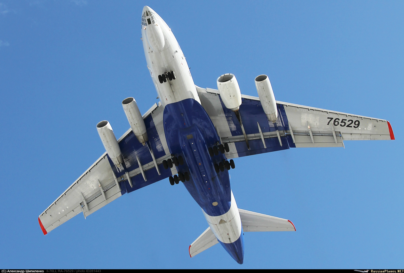
Scan from Kodachrome K25 slide.
On 2 September 2005, 37109 tows 960201 (formed from class 310 vehicles) from Ramsgate to Ilford. This unit was used as a testbed for the class 395 traction equipment.
N804X operated by Northrup Grumman Systems Corp Bombardier CRJ700-701 Flying testbed, seen landing at Baltimore MD 16th Dec 2021
"#harrymorrowphoto1
flickr.com/harrymorrowphotography
harrymorrowphotography.com
globalairpower.net"
Boeing 737-683
cn: 28297 / ln: 30
ff: 02-03-1998 N1786B
02-03-1998 N35135 rr Boeing testbed for C of A for the B737-600 series
21-01-1999 SE-DNS SAS "Signe Viking" config CY112
28-07-2001 LN-RRY rr SAS "Signe Viking"
02-2005 Painted in SAS Braathens colours as the first 736, and opf SAS Braathens from 01-04-2005 (allthough AoC change to CNO was officially made 20-04-2006 for LN-RRY ).
01-07-2007 LN-RRY SAS Norge "Signe Viking", op in SAS Braathens ciolours,
cfr photo as it arrives rwy 19R as SK1499 from Stockholm in september 07.
SAS Norge colour update was not before 12-2008 (!)
01-10-2009 Scandinavian Airlines - SAS tfd, "Signe Viking" config CY120
Again: LN-RRY did not get updated to std SAS colours before 2013 (.... )
07-08-2019 wfu and std ENGM/OSL, after 20,5 years in SAS service
27-08-2019 Departed ENGM/OSL at 13:20 pm as SK9121 to St. Athan EGSY/DGX for part-out and scrap
The Canadair CT-133 Silver Star (company model number CL-30) is the Canadian license-built version of the Lockheed T-33 jet trainer aircraft, in service from the 1950s to 2005. The Canadian version was powered by the Rolls-Royce Nene 10 turbojet, instead of the original Allison J33.
The Canadair CT-133 was the result of a 1951 contract to build T-33 Shooting Star trainers for the Royal Canadian Air Force (RCAF) with a Rolls-Royce Nene 10 turbojet. A project designation of CL-30 was given by Canadair and the name was changed to Silver Star. The CT-133's appearance is distinctive due to the large fuel tanks usually carried on the wingtips. Canadair built 656 CT-133 aircraft.
The CT-133 entered service in the RCAF as its training aircraft for fighters. The designation of the Silver Star in the Canadian Forces was CT-133. The CT-133's service career in the RCAF (and later the Canadian Forces) was extremely long. One of the more unusual roles it played was as an aerobatic demonstration aircraft, the RCAF's Red Knight. Although the aircraft stopped being used as a trainer in 1976, there were still over 50 aircraft in Canadian Forces inventory in 1995. The newest of these was then 37 years old and had exceeded its expected life by a factor of 2.5. During this period, the Canadair T-33 was employed in communication, target towing, and enemy simulation.
The final Silver Star Mk. 3 was retired from the Aerospace Engineering Test Establishment at CFB Cold Lake, Alberta, where it was used as an ejection seat testbed for 46 years, when it was sold as surplus on the civil market, with fifteen other CT-133s to join fifty others on the US Civil Register.
Description: Perseus A, a remotely piloted, high-altitude research vehicle designed by Aurora Flight Sciences Corp., takes off from Rogers Dry Lake at the Dryden Flight Research Center, Edwards, California. The Perseus was towed into the air by a ground vehicle. At about 700 ft. the aircraft was released and the engine turned the propeller to take the plane to its desired altitude. Perseus B is a remotely piloted aircraft developed as a design-performance testbed under NASA's Environmental Research Aircraft and Sensor Technology (ERAST) project. Perseus is one of several flight vehicles involved in the ERAST project. A piston engine, propeller-powered aircraft, Perseus was designed and built by Aurora Flight Sciences Corporation, Manassas, Virginia. The objectives of Perseus B's ERAST flight tests have been to reach and maintain horizontal flight above altitudes of 60,000 feet and demonstrate the capability to fly missions lasting from 8 to 24 hours, depending on payload and altitude requirements. The Perseus B aircraft established an unofficial altitude record for a single-engine, propeller-driven, remotely piloted aircraft on June 27, 1998. It reached an altitude of 60,280 feet. In 1999, several modifications were made to the Perseus aircraft including engine, avionics, and flight-control-syste m improvements. These improvements were evaluated in a series of operational readiness and test missions at the Dryden Flight Research Center, Edwards, California. Perseus is a high-wing monoplane with a conventional tail design. Its narrow, straight, high-aspect-ratio wing is mounted atop the fuselage. The aircraft is pusher-designed with the propeller mounted in the rear. This design allows for interchangeable scientific-instrumen t payloads to be placed in the forward fuselage. The design also allows for unobstructed airflow to the sensors and other devices mounted in the payload compartment. The Perseus B that underwent test and development in 1999 was the third generation of the Perseus design, which began with the Perseus Proof-Of-Concept aircraft. Perseus was initially developed as part of NASA's Small High-Altitude Science Aircraft (SHASA) program, which later evolved into the ERAST project. The Perseus Proof-Of-Concept aircraft first flew in November 1991 and made three low-altitude flights within a month to validate the Perseus aerodynamic model and flight control systems. Next came the redesigned Perseus A, which incorporated a closed-cycle combustion system that mixed oxygen carried aboard the aircraft with engine exhaust to compensate for the thin air at high altitudes. The Perseus A was towed into the air by a ground vehicle and its engine started after it became airborne. Prior to landing, the engine was stopped, the propeller locked in horizontal position, and the Perseus A glided to a landing on its unique bicycle-type landing gear. Two Perseus A aircraft were built and made 21 flights in 1993-1994. One of the Perseus A aircraft reached over 50,000 feet in altitude on its third test flight. Although one of the Perseus A aircraft was destroyed in a crash after a vertical gyroscope failed in flight, the other aircraft completed its test program and remains on display at Aurora's facility in Manassas. Perseus B first flew October 7, 1994, and made two flights in 1996 before being damaged in a hard landing on the dry lakebed after a propeller shaft failure. After a number of improvements and upgrades-including extending the original 58.5-foot wingspan to 71.5 feet to enhance high-altitude performance--the Perseus B returned to Dryden in the spring of 1998 for a series of four flights. Thereafter, a series of modifications were made including external fuel pods on the wing that more than doubled the fuel capacity to 100 gallons. Engine power was increased by more than 20 percent by boosting the turbocharger output. Fuel consumption was reduced with fuel control modifications and a leaner fuel-air mixture that did not compromise power. The aircraft again crashed on October 1, 1999, near Barstow, California, suffering moderate damage to the aircraft but no property damage, fire, or injuries in the area of the crash. Perseus B is flown remotely by a pilot from a mobile flight control station on the ground. A Global Positioning System (GPS) unit provides navigation data for continuous and precise location during flight. The ground control station features dual independent consoles for aircraft control and systems monitoring. A flight termination system, required for all remotely piloted aircraft being flown in military-restricted airspace, includes a parachute system deployed on command plus a C-Band radar beacon and a Mode-C transponder to aid in location. Dryden has provided hanger and office space for the Perseus B aircraft and for the flight test development team when on site for flight or ground testing. NASA's ERAST project is developing aeronautical technologies for a new generation of remotely piloted and autonomous aircraft for a variety of upper-atmospheric science missions and commercial applications. Dryden is the lead center in NASA for ERAST management and operations. Perseus B is approximately 25 feet long, has a wingspan of 71.5 feet, and stands 12 feet high. Perseus B is powered by a Rotax 914, four-cylinder piston engine mounted in the mid-fuselage area and integrated with an Aurora-designed three-stage turbocharger, connected to a lightweight two-blade propeller.
Credit: NASA/Jim Bean
Image Number: EC94-42461-2
Date: 1994
Raytheon Company "Voodoo One" 727-223 (N289MT) Experimental Testbed aircraft departing LAX from Runway 25R. (03/16/16)
This is the first landing of an Airbus A350XWB in Frankfurt. On July 25, 2014 at 18:38h local time F-WWYB has arrived on runway 25C.
MSN 005 has had its first flight on 20.06.14. It is powered by 2x Rolls-Royce Trent XWB turbofans and is currently used as a testbed.
This is flight AIB102 from Iqaluit/Canada.
Please join my Facebook fan page:
www.facebook.com/pages/Thomas-Becker-Aviation-Photography...
...and there is a Plane Spotting group on Facebook you should visit:
www.facebook.com/groups/planespotting/
Flickr has done some major design changes (which I deeply regret). Are you missing collections in Flickr? Me, too!
But they are not lost, just hidden - you can go there by using one of the following links:
Special Aviation Photos
www.flickr.com/photos/thomasbecker/collections/7215762339...
Airlines of the World
www.flickr.com/photos/thomasbecker/collections/7215760571...
Aviation by Date
www.flickr.com/photos/thomasbecker/collections/7215760307...
Airline Alliances of the World
www.flickr.com/photos/thomasbecker/collections/7215762573...
Some background:
The VF-1 was developed by Stonewell/Bellcom/Shinnakasu for the U.N. Spacy by using alien Overtechnology obtained from the SDF-1 Macross alien spaceship. Its production was preceded by an aerodynamic proving version of its airframe, the VF-X. Unlike all later VF vehicles, the VF-X (sometimes referred to as VF-X1) was strictly a conventional/non-transformable jet aircraft, even though it incorporated many structural components and several key technologies that were vital for the transformable VF-1’s successful development that ran in parallel. Therefore, the VF-X was never intended as an air superiority fighter, but rather a flight-capable analogue test bed and proof of concept for the VF-1’s basic layout and major components. In this role, however, the VF-X made vital contributions to systems’ development that were later incorporated into the VF-1’s serial production and sped the program up considerably.
VF-X production started in early 2006, with four airframes built. The flight tests began in February 2007. The first prototype (“01”) was piloted and evaluated by ace pilot Roy Fokker, in order to explore the aircraft’s flight envelope, general handling and for external stores carriage tests. The three other VF-Xs successively joined the test program, each with a different focus. “02” was primarily tasked with the flight control and pilot interface program, “03” was allocated to the engine, vectoring thrust and steering systems development, and “04” was primarily involved in structural and fatigue tests.
In November 2007, the successful VF-X tests and the flights of the VF-X-1 (the first fully transformable VF-1 prototype, which had been under construction in parallel to the VF-X program) led to formal adoption of the “Valkyrie” variable fighter by the United Nations Government.
The space-capable VF-1's combat debut was on February 7, 2009, during the Battle of South Ataria Island - the first battle of Space War I - and remained the mainstay fighter of the U.N. Spacy for the entire conflict.
Introduced in 2008, the VF-1 proved to be an extremely capable craft, successfully combating a variety of Zentraedi mecha, even in most sorties which saw UN Spacy forces significantly outnumbered. The versatility of the Valkyrie design enabled the variable fighter to act as both large-scale infantry and as air/space superiority fighter. The signature skills of U.N. Spacy ace pilot Maximilian Jenius exemplified the effectiveness of the variable systems as he near-constantly transformed the Valkyrie in battle to seize advantages of each mode as combat conditions changed from moment to moment.
The basic VF-1 was deployed in four sub-variants (designated A, D, J, and S) and its success was increased by continued development of various enhancements. These included the GBP-1S "Armored Valkyrie” external armor and infantry weapons pack, so-called FAST Packs for "Super Valkyries” for orbital use, and the additional RÖ-X2 heavy cannon pack weapon system for the VF-1S “Strike Valkyrie” with additional firepower.
After the end of Space War I, the VF-1 continued to be manufactured both in the Sol system and throughout the UNG space colonies. Although the VF-1 would eventually be replaced as the primary Variable Fighter of the U.N. Spacy by the more capable, but also much bigger, VF-4 Lightning III in 2020, a long service record and continued production after the war proved the lasting worth of the design.
The VF-1 was without doubt the most recognizable variable fighter of Space War I and was seen as a vibrant symbol of the U.N. Spacy even into the first year of the New Era 0001 in 2013. At the end of 2015 the final rollout of the VF-1 was celebrated at a special ceremony, commemorating this most famous of variable fighters. The VF-1 Valkryie was built from 2006 to 2013 with a total production of 5,459 VF-1 variable fighters with several variants (VF-1A = 5,093, VF-1D = 85, VF-1J = 49, VF-1S = 30, VF-1G = 12, VE-1 = 122, VT-1 = 68), and several upgrade programs were introduced.
The fighter remained active in many second line units and continued to show its worthiness years later, e. g. through Milia Jenius who would use her old VF-1 fighter in defense of the colonization fleet - 35 years after the type's service introduction.
General characteristics:
Accommodation: One pilot in a Marty & Beck Mk-7 zero/zero ejection seat
Length 14.23 meters
Wingspan 14.78 meters (at 20° minimum sweep)
Height 3.84 meters
Empty weight: 13.25 metric tons
Standard T-O mass: 18.5 metric tons
Power Plant:
2x Shinnakasu Heavy Industry/P&W/Roice FF-2001 thermonuclear reaction turbine engines, output 650 MW each, rated at 11,500 kg in standard or in overboost (225.63 kN x 2)
4 x Shinnakasu Heavy Industry NBS-1 high-thrust vernier thrusters (1 x counter reverse vernier thruster nozzle mounted on the side of each leg nacelle/air intake, 1 x wing thruster roll control system on each wingtip);
Performance:
Top speed: Mach 2.71 at 10,000 m; Mach 3.87 at 30,000+ m
Thrust-to-weight ratio: empty 3.47; standard T-O 2.49; maximum T-O 1.24
Armament:
None installed, but the VF-X had 4x underwing hard points for a wide variety of ordnance, plus a ventral hardpoint for a Howard GU-11 55 mm three-barrel Gatling gun pod with 200 RPG, fired at 1,200 rds/min or other stores like test instruments
The model and its assembly:
Another submission to the “Prototypes” group build at whatifmodelers.com in July 2020. Being a VF-1 fan (and have built maybe twenty o these simple Arii kits), adding a VF-X was, more or less, a must – even more so because I had a suitable Valkyrie Fighter kit at hand for the conversion. As a side note, I have actually built something quite similar from a VF-1D many years ago: a fictional, non-transformable advanced trainer, without knowing about the VF-X at all.
Thanks to the “Macross - Perfect Memory” source book, the differences between the transformable VF-1 and its early testbed were easy to identify:
- Fixed legs with faired ducts from the intakes on (thighs)
- Ankle recesses disappeared
- Less and slightly different panel lines on the back and on the nose
- ventral head unit deleted and a respective fairing installed instead
- Levelled underside (shoulder fairings of the folded arms were cut down)
- Leg attachment points on the nose deleted
- No small, circular vernier thrusters all around the hull
- Some new/different venting grills (created mostly with 0.5mm black decal stripes)
Beyond the changes, the VF-1A was basically built OOB. Thankfully, the VF-X already features the later VF-1’s vectored thrust nozzles/feet, so that no changes had to be made in this respect. A pilot figure was added to the cockpit for the beauty pics, and after the flight scenes had been shot, the canopy remained open on a swing arm for static display. For the same reason, the model was built with the landing gear extended.
As a test aircraft, the underwing pylons and their AMM-1 ordnance were left away and the attachment points hidden with putty. I also omitted the ventral gun pod and left the aircraft clean. However, for the flight scene pictures, I implanted an adapter for a display holder made from wire.
In order to emphasize the test vehicle character of the VF-X, I gave the model a scratched spin recovery parachute installation between the fins, using a real world F-22 testbed as benchmark. It consists of styrene profiles, quite a delicate construction. For the same reason I gave the VF-X a long sensor boom on the nose, which changes the Valkyrie’s look, too. Finally, some small blade antennae were added to the nose and to the spine behind the cockpit.
Painting and markings:
To be honest, I have no idea if there was only a single VF-X prototype in the Macross universe, or more. Just one appears in the TV series in episode #33, and lack of suitable information and my personal lack of Japanese language proficiency prevents any deeper research. However, this would not keep me from inventing a personal interpretation of the canonical VF-X, especially because I do not really like the original livery from the TV series: an overall light grey with some simple black trim and “TEST” written on the (fixed) legs. Yamato did an 1:60 scale toy of the VF-X, but it was/is just a VF-1 with a ventral fairing; they added some shading to the basic grey – but this does not make the aircraft more attractive, IMHO.
When I looked at the original conceptual drawing of the VF-X in the “Macross - Perfect Memory” source book, however, I was immediately reminded of the F-15 prototypes from the Seventies (and this program used a total of twelve machines!). These featured originally a light grey (FS 36375?) overall base, to which bright dayglo orange markings on wings, fins and fuselage were soon added – in a very similar pattern to the VF-X. I think the VF-X livery was actually inspired by this, the time frame matches well with the production of the Macross TV series, too, and that’s what I adapted for my model.
In order to come close to the F-15 prototype livery, I gave “my” VF-X an overall basic coat of RAL 7047 “Telegrau 4”, one of German Telekom’s corporate colors and a very pale grey that can easily be mistaken for white when you do not have a contrast reference.
The cockpit received a medium grey finish, the ejection seat became black with brown cushions; the pilot figure is a 1:100 seated passenger from an architecture supplies, painted like an early VF-1 pilot in a white/blue suit. The jet nozzles/feet were painted with Revell 91 (Iron) and later treated with grinded graphite for a more metallic finish. The landing gear became classic white (I used Revell 301, which is a very pure tone, as contrast to the RAL 7047 on the hull), the air intake ducts and the internal sections of the VG wings were painted with dark grey (Revell 77).
For some diversity I took inspiration from the Yamato VF-X toy and added slightly darker (Humbrol 166, RAF Light Aircraft Grey) areas to the hull and the legs. Next, the panel lines were emphasized through a thinned black ink wash, but I did no panel post shading so that the VF-X would not look too dirty or worn.
Onto this basis I applied the orange dayglo markings. On the wings and fins, these were painted – they were applied with spray paint from a rattle can, involving lots of masking. The leading edges on wings and fins were created with grey decal sheet material, too. At this stage, some surface details and more fake panel lines were added with a soft pencil.
The orange cheatline under the cockpit is a personal addition; I found that some more orange had to be added to the nose for visual balance, and I eventually went for the simple, trimmed stripe (TL Modellbau material) instead of trying to apply decal sheet material around the jagged air intakes (F-15 prototype style). The black “TEST”, “VFX” and “U.N. Spacy” markings were designed at the computer and printed on clear inkjet decal paper. Even though the “real” VF-X does not feature the UNS “kite” insignia, I decided to add them to the model. These come from the OOB sheet, which also provided most (slightly yellowed) stencils.
Finally, the model was sealed with a coat of matt acrylic varnish (Italeri).
A rather different VF-1 project (and it is – to my astonishment – #28 in my 1:100 VF-1 Fighter mode collection!!!), with more changes to the basic model kit than one might expect at first sight. VF-X and VF-1 differ considerably from each other, despite identical outlines! However, I like the outcome, and I think that going a different route from the canonical grey/black livery paid out, the bright orange markings really make this VF-X stand out, and it looks IMHO more like a testbed than the “real” aircraft from the TV series.
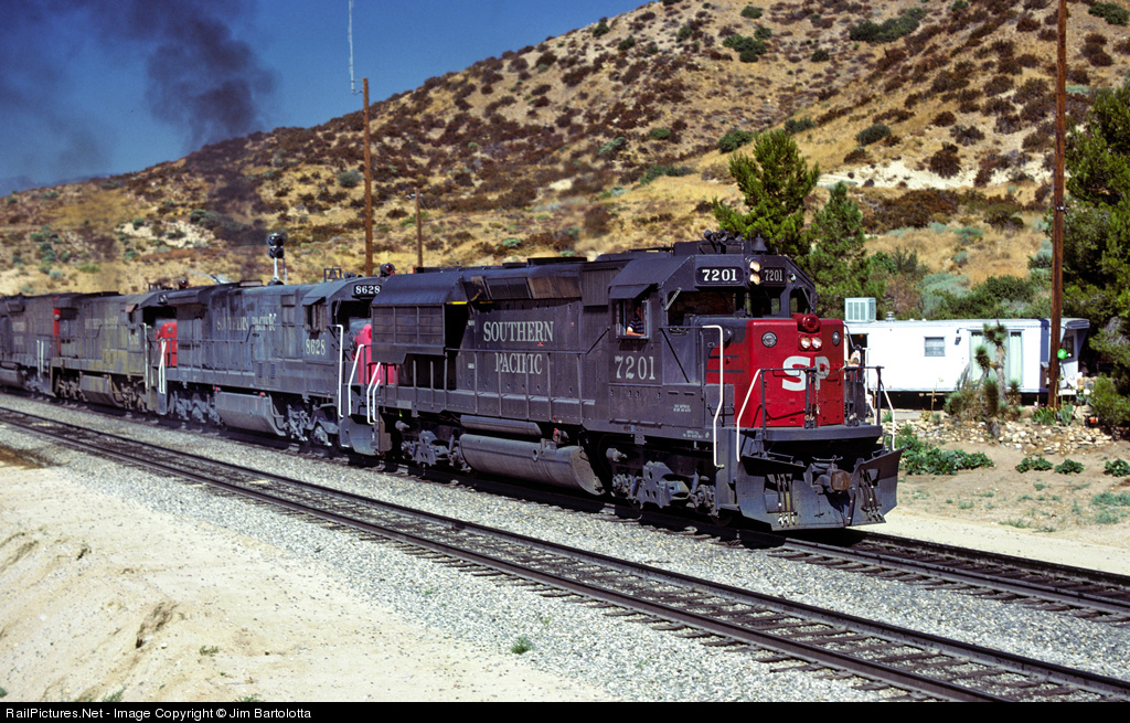
I'm sure these two units have really been through a lot over their lives, but few locomotives have as hard of a life as a testbed like EMDX 91. Taken at Mid-America Car in Kansas City.
Locomotives: CITX 3079, EMDX 91
2-17-13
Kansas City, MO
In 1961, the testbed aircraft Ye-7SPS demonstrated a flap-blowing system where the air is forced over the flap surface to increase stability at lower air speeds. This system found its way onto the MiG-21PFS (Model 94; NATO reporting name: “Fishbed-D/F”). The first nine production batches of the MiG-21PFS (Fishbed-D/F) were externally identical to the MiG-21PF (Fishbed-D) but with blown flaps and a brake chute fairing at the fin’s base. From batches 10 to 19, the large chord vertical stabilizer first seen on the MiG-21FL (Fishbed-D) was introduced, but the aircraft retained the SK ejection seat and one piece, the forward-opening canopy of the MiG-21PF. From batch 20 onwards, the MiG-21PFS aircraft had a wide-chord tail, a KM-1 ejection seat and a two-piece, sideways-opening canopy.
In this image, a later batch MiG-21PFS (Fishbed-F) flying with the 85th Guards Fighter Aviation Regiment unloads its UB-16-57U rocket launcher. You can see the larger tail fin and the sideways-opening canopy (barely). This model has functioning flaps and speed brakes open on this attack run. The forward speed brakes were fitted when the cannons were removed, and additional fuel tanks were inserted.
The growing worldwide demand for air travel during the 1960s led Boeing to launch the 747, the first wide-body jet. Developing what was then the world's largest passenger aircraft was a formidable undertaking, requiring the company to risk much of its net worth. But the gamble paid off – over 1,500 units have been produced. With its massive size and signature upper deck "hump," the iconic 747 is one the most recognizable aircraft in the world. It triggered a revolution in air travel and represents a significant milestone in the evolution of aviation design.
The leviathan 747 required an all-new factory, which was built almost simultaneously with the first 747 at Paine Field in Everett, Washington. First flight occurred on February 9, 1969, followed by an extensive test program. The first 747 engine, the Pratt & Whitney JT9D, was an equally challenging engineering effort; it experienced numerous problems in initial service.
The 747 quickly became a mainstay of the world’s international airlines. Continued development in the ensuing years has increased payload, range, and capability with multiple 747 variants. A freighter model, with a large nose cargo door, allows outsized payloads to be carried. A "Combi" was soon offered to allow simultaneous carriage of passengers and cargo on the main deck. A shortened version (747SP) debuted in 1976, capable of very long range flights. The 747-300 followed in 1982, with an extended upper deck. In 1989, a major upgrade was introduced in the form of the 747-400, with a modernized two-crew flight deck and improved performance. The 747-8, with all-new wings and engines, entered service in 2011.
The airplane proved to be highly flexible, performing many missions that were not part of its original design specifications. Two 747-100s were modified to become Shuttle Carrier Aircraft for the NASA Space Shuttle Program. Several aircraft were produced to serve as U.S. Air Force "command post" platforms, designated E-3 and E-4. In 1990, two 747-200Bs were modified as VC-25As to serve as Air Force One, the U.S. Presidential aircraft. Other unique modifications include the enlarged "Dreamlifter" for 787 components, the YAL-1A Airborne Laser Testbed, and the Stratospheric Observatory for Infrared Astronomy (SOFIA).
The Museum's aircraft was the first 747 ever built, known as RA001. After 747 certification testing, the aircraft served for many years as a company testbed for technology development and new engine programs for other Boeing commercial jets, including the Pratt & Whitney PW4000 for the Boeing 777. Planning for eventual donation to the Museum began in the mid-1980s. The aircraft's final flight occurred on April 6, 1995, when Boeing officially donated RA001 to the Museum after 5,300 flight hours. Still configured in its flight test configuration, it was extensively restored in 2013 and 2014.
The GP40X was EMD's testbed for the future GP50 and introduced the unpopular HT-B truck. The 'elephant ears' version shown here was an experiment in normalizing the tunnel motor concept. The ears eventually were removed and the HT-B trucks were never reproduced. I needed a powered SP unit to haul around some heavy trains so all those unique qualities fit the bill just right. Originally I wanted to build the UP version, but the SP is more iconic with those elephant ears. The UP version will follow someday.
What turns out to be 150002's last voyage down here in Devon, as immediately after finishing this Plymouth to Exeter St David's service, the crew was changed and the unit set off immediately for it's home at Reading, ending it's relief services here in the South West.
The original prototype Class 150's date back to 1984, when British Rail was considering a new fleet of Diesel Multiple Units to replace ageing 1st Generation DMU's in years following the creation of the Regional Railways sector. Three types of units were considered, the Class 150 built by BREL, the Class 151 built by Metro-Cammel and the Class 155 built by British Leyland. The two prototypes were also testbeds for new unit engines, 150001 being fitted with a Cummins engine that was fitted to the production fleet, whilst 150002 was fitted with a Rolls Royce engine, but this was later changed to a standard Cummins engine. Eventually the Class 150's and 155's were chosen as the main fleet of units for the local and provincial routes, the 155's later being split up to form the single-car Class 153's.
Following the successful tests of these units, the two prototype Class 150's went into service in the West Midlands, operating for the Centro brand around Birmingham. These units have very few distinguishing features to the production fleet of Class 150/1's, aside from the fact that these units are formed of three coaches, including an intermediate trailer. The remainder of the Class 150 fleet was built as only two cars, although in recent years hybrid 3-car Class 150's have been made using single Class 150/2 carriages as intermediate trailers.
In 2011, the introduction of the Class 172's resulted in a mass withdrawal of Class 150's from the West Midlands, and thus the prototype Class 150's were taken on along with many other ex-Central Trains and London Midland units by First Great Western. This particular outing for this unit is abnormal as the two prototype units are employed in working the Basingstoke to Reading shuttle service in lieu of a Class 165 'Thames Turbo' unit, which makes its appearance here in Devon all the more special.
Quality is a bit hit and miss I'm afraid as it was taken in a rush on my phone. As I walked into the station I had only noticed at the last minute that this was the prototype! xD
TF-ATD Boeing 747-200 of Air Atlanta Icelandic at Manchester 16/5/04.
Now used as an engine testbed with Rolls Royce as N787RR at Marana-Pinal Airpark
After the accident of CCCP-77111, this aircraft and CCCP-77113 were used as testbed until the Tu-144D model obtained the certificate of airworthiness in the beginning of 80's. As result of 50 trial flights between Moscow and Khabarovsk was recommended to operate with passengers but, unlike Tu-144S, this never happened.
When the Tu-144 program was cancelled, 07-1 was stored at Zhukovsky for almost twenty years until a private German museum bought her by $500,000.
In October 2000 the nose, tail and wings were removed and CCCP-77112 was shipped on a barge for a trip from Moscow to Sinsheim via Baltic sea of more than 4,000 km. The aircraft was re-assembled and on March 2001 lifted to the roof of the museum where today is on display.
This is the only one Tu-144 on display out of Russia.
Maiden Flight: 19th February 1979 : Voronezh, USSR.
Final Flight: 12th November 1981.
Total Flights: 87 flights.
Supersonic Flights:29 flights.
Total Flight Hours: 197 hours, 45 minutes.
Supersonic Flight Hours: 46 hours, 38 minutes.
Current UsageOn display on the roof of the Auto & Technik Museum in Sinsheim, Germany.
DISCLAIMER
Nothing you see here is real, even though the conversion or the presented background story might be based historical facts. BEWARE!
Some background:
The Northrop Grumman-IAI F-24 is the latest reincarnation of the USAF "Lightweight Fighter Program" which dates back to the 1950ies and started with the development of Northrop's F-5 "Freedom Fighter".
The 1st generation F-5 became very successful in the export market and saw a long line of development, including the much more powerful F-5E "Tiger II" and the F-20 Tigershark (initially called F-5G). Northrop had high hopes for the F-20 in the international market; however, policy changes following Ronald Reagan's election meant the F-20 had to compete for sales against aircraft like the F-16, the USAF's latest fighter design (which was politically favored). The F-20 development program was eventually abandoned in 1986 after three prototypes had been built and a fourth partially completed.
But this was not the end for Northrop’s Lightweight Fighter. In the early 1980s, two X-29As experimental aircraft were built by Grumman from two existing Northrop F-5A Freedom Fighter airframes. The Grumman X-29 was a testbed for forward-swept wings, canard control surfaces, and other novel aircraft technologies. The aerodynamic instability of this arrangement increased agility but required the use of computerized fly-by-wire control. Composite materials were used to control the aeroelastic divergent twisting experienced by forward-swept wings, also reducing the weight. The NASA test program continued from 1984 to 1991 and the X-29s flew 242 times, gathering valuable data and breaking ground for new aerodynamic technologies of 4th and 5th generation fighters.
Even though no service aircraft directly evolved from the X-29, its innovative FBW system as well as the new material technologies also opened the door for an updated F-20 far beyond the 1990ies. It became clear that ever expensive and complex aircraft could not be the answer to modern, asymmetrical warfare in remote corners of the world, with exploding development costs and just a limited number of aircraft in service that could not generate true economies of scale, esp. when their state-of-the-art design would not permit any export.
Anyway, a global market for simpler fighter aircraft was there, as 1st generation F-16s as well as the worldwide, aging F-5E fleet and types of Soviet/Russian origin like the MiG-29 provided the need for a modern, yet light and economical jet fighter. Contemporary types like the Indian HAL Tejas, the Swedish Saab Gripen, the French Dassault Rafale and the Pakistani/Chinese FC-1/JF-17 ”Thunder” proved this trend among 4th - 4.5th generation fighter aircraft.
Northrop Grumman (Northrop bought Grumman in 1994) initiated studies and basic design work on a respective New Lightweight Fighter (NLF) as a private venture in 1995. Work on the NLF started at a slow pace, as the company was busy with re-structuring.
The idea of an updated lightweight fighter was fueled by another source, too: Israel. In 1998 IAI started looking in the USA for a development partner for a new, light fighter that would replace its obsolete Kfir fleet and partly relieve its F-16 and F-15 fleet from interception tasks. The domestic project for that role, the IAI Lavi, had been stillborn, but lots of its avionics and research were still at hand and waited for an airframe for completion.
The new aircraft for the IAF was to be superior to the MiG-29, at least on par with the F-16C/D, but easier to maintain, smaller and overall cheaper. Since the performance profiles appeared to be similar to what Northrop Grumman was developing under the NLF label, the US company eventually teamed up with IAI in 2000 and both started the mutual project "Namer" (=נמר, “Tiger” in Hebrew), which eventually lead to the F-24 I for the IAF which kept its project name for service and to the USAF’s F-24A “Tigershark”.
The F-24, as the NLF, was based on the F-20 airframe, but outwardly showed only little family heritage, onle the forward fuselage around the cockpit reminds of the original F-5 design . Many aerodynamic details, e. g. the air intakes and air ducts, were taken over from the X-29, though, as the experimental aircraft and its components had been developed for extreme maneuvers and extra high agility. Nevertheless, the X-29's forward-swept wing was considered to be too exotic and fragile for a true service aircraft, but the F-24 was to feature an Active Aeroelastic Wing (AAW) system.
AAW Technology integrates wing aerodynamics, controls, and structure to harness and control wing aeroelastic twist at high speeds and dynamic pressures. By using multiple leading and trailing edge controls like "aerodynamic tabs", subtle amounts of aeroelastic twist can be controlled to provide large amounts of wing control power, while minimizing maneuver air loads at high wing strain conditions or aerodynamic drag at low wing strain conditions. This system was initially tested on the X-29 and later on the X-53 research aircraft, a modified F-18, until 2006.
Both USAF and IAF versions feature this state-of-the-art aerodynamic technology, but it is uncertain if other customers will receive it. While details concerning the F-24's system have not been published yet, it is assumed that its AAW is so effective that canard foreplanes could be omitted without sacrificing lift and maneuverability, and that drag is effectively minimized as the wing profile can be adjusted according to the aircraft’s speed, altitude, payload and mission – much like a VG wing, but without its clumsy and heavy swiveling mechanism which has to bear high g forces. As a result, the F-24 is, compared to the F-20, which could carry an external payload of about 3.5 tons, rumored to be able to carry up to 5 tons of ordnance.
The delta wing shape proved to be a perfect choice for the required surface and flap actuators inside of the wings, and it would also offer a very good compromise between lift and drag for a wide range of performance. Anyway, there was one price to pay: in order to keep the wing profile thin and simple, the F-24’s landing gear retracts into the lower fuselage, leaving the aircraft with a relatively narrow track.
Another major design factor for the outstanding performance of this rather small aircraft was weight reduction and structural integrity – combined with simplicity, ruggedness and a modular construction which would allow later upgrades. Instead of “going big” and expensive, the new F-24 was to create its performance through dedicated loss of weight, which was in some part also a compensation for the AAW system in the wings and its periphery.
Weight was saved wherever possible, e .g. a newly developed, lightweight M199A1 gatling gun. This 20mm cannon is a three-barreled, heavily modified version of the already “stripped” M61A2 gun in the USAF’s current F-18E and F-22. One of the novel features is a pneumatic drive instead of the traditional electric mechanism, what not only saves weight but also improves trigger response. The new gun weighs only a mere 65kg (the six-barreled M61A2 weighs 92kg, the original M61A1 112 kg), but still reaches a burst rate of fire of 1.800 RPM (about 800 RPM under cyclic fire, standard practice is to fire the cannon in 30 to 50-round bursts, though) and a muzzle velocity of 1.050 metres per second (3,450 ft/s) with a PGU-28/B round.
While the F-16 was and is still made from 80% aluminum alloys and only from 3% composites, the F-24 makes major use of carbon fiber and other lightweight materials, which make up about 40% of the aircraft’s structure, plus an increased share of Titanium and Magnesium alloys. As a consequence and through many other weight-saving measures like keeping stealth capabilities to a minimum (even though RAM was deliberately used and many details designed to have a natural low radar signature, resulting in modest radar cross-section (RCS) reductions), a single, relatively small engine, a fuel-efficient F404-GE-402 turbofan, is enough to make the F-24 a fast and very agile aircraft, coupled with a good range. The F-24’s thrust/weight ratio is considerably higher than 1, and later versions with a vectored thrust nozzle (see below) will take this level of agility even further – with the pilot becoming the limiting factor for the aircraft’s performance.
USAF and IAF F-24s are outfitted with Northrop Grumman's AN/APG-80 Active Electronically Scanned Array (AESA) radar, also used in the F-16 Block 60 aircraft. Other customers might only receive the AN/APG-68, making the F-24 comparable to the F-16C/D.
The first prototype, the YF-24, flew on 8th of March 2008, followed by two more aircraft plus a static airframe until summer 2010. In early 2011 the USAF placed an initial order of 101 aircraft (probably also to stir export sales – the earlier lightweight fighters from Northrop suffered from the fact that the manufacturer’s country would not use the aircraft in its own forces). These initial aircraft will replace older F-16 in the interceptor role, or free them for fighter bomber tasks. The USN and USMC also showed interest in the aircraft for their aggressor squadrons, for dissimilar air combat training. A two-seater, called the F-24B, is supposed to follow soon, too, and a later version for 2020 onwards, tentatively designated F-24C, is to feature an even stronger F404 engine and a 3D vectoring nozzle.
Israel is going to produce its own version domestically from late 2014 on, which will exclusively be used by the IAF. These aircraft will be outfitted with different avionics, built by Elta in Israel, and cater to national requirements which focus more on multi-purpose service, while the USAF focusses with its F-24A on aerial combat and interception tasks.
International interest for the F-24A is already there: in late 2013 Grumman stated that initial talks have been made with various countries, and potential export candidates from 2015 on are Taiwan, Singapore, Thailand, Finland, Norway, Australia and Japan.
General F-24A characteristics:
Crew: 1 pilot
Length: 47 ft 4 in (14.4 m)
Wingspan: 27 ft 11.9 in / 8.53 m; with wingtip missiles (26 ft 8 in/ 8.13 m; without wingtip missiles)
Height: 13 ft 10 in (4.20 m)
Wing area: 36.55 m² (392 ft²)
Empty weight: 13.150 lb (5.090 kg)
Loaded weight: 15.480 lb (6.830 kg)
Max. take-off weight: 27.530 lb (12.500 kg)
Powerplant
1× General Electric F404-GE-402 turbofan with a dry thrust of 11,000 lbf (48.9 kN) and 17,750 lbf (79.2 kN) with afterburner
Performance
Maximum speed: Mach 2
Combat radius: 300 nmi (345 mi, 556 km); for hi-lo-hi mission with 2 × 330 US gal (1,250 L) drop tanks
Ferry range: 1,490 nmi (1715 mi, 2759 km); with 3 × 330 US gal (1,250 L) drop tanks
Service ceiling: 55,000 ft (16,800 m)
Rate of climb: 52,800 ft/min (255 m/s)
Wing loading: 70.0 lb/ft² (342 kg/m²)
Thrust/weight: 1.09 (1.35 with loaded weight & 50% fuel)
Armament
1× 20 mm (0.787 in) M199A1 3-barreled Gatling cannon in the lower fuselage with 400 RPG
Eleven external hardpoints (two wingtip tails, six underwing hardpoints, three underfuselage hardpoints) and a total capacity of 11.000 lb (4.994 kg) of missiles (incl. AIM 9 Sidewinder and AIM 120 AMRAAM), bombs, rockets, ECM pods and drop tanks for extended range.
The kit and its assembly:
A spontaneous project. This major kitbash was inspired by fellow user nighthunter at whatifmodelers.com, who came up with a profile of a mashed-up US fighter, created “out of boredom”. The original idea was called F-21C, and it was to be a domestic successor to the IAI Kfirs which had been used by the US as aggressor aircraft in USN and USMC service for a few years.
As a weird(?) coincidence I had many of the necessary ingredients for this fictional aircraft in store, even though some parts and details were later changed. This model here is an interpretation of the original design. The idea was spun further, and the available parts that finally went into the model also had some influence on design and background.
I thank nighthunter for sharing the early ideas, inviting me to take the design to the hardware stage (sort of…) and adapting my feedback into new design sketches, too, which, in return, inspired the model building process.
Well, what went into this thing? To cook up a F-24 à la Dizzyfugu you just need (all in 1:72):
● Fuselage from a Hasegawa X-29, including the cockpit and the landing gear
● Fin and nose cone from an Italeri F-16A
● Inner wings from a (vintage) Hasegawa MiG-21F
● Outer wings from a F-4 (probably a J, Hasegawa or Fujimi)
The wing construction deviates from nighthunter’s original idea. The favorite ingredients would have been F-16XL or simple Mirage III wings, but I found the composite wing to be more attractive and “different”. The big F-16XL wings, despite their benefit of a unique shape, might also have created scale/size problems with a F-20 style fuselage? So I built hybrid wings: The MiG-21 landing gear wells were filled with putty and the F-4 outer wings simply glued onto the MiG inner wing sections, which were simply cut down in span. It sounds like an unlikely combo, but these parts fit together almost perfectly! In order to hide the F-4 origins I modified them to carry wingtip launch rails, though, which were also part of nighthunter’s original design.
The AAW technology detail mentioned in the background came in handy as it explains the complicated wing shape and the fact that the landing gear retracts into the fuselage, not into the wings, which would have been more plausible… Anyway, there’s still room for a simpler export version, with Mirage III or Kfir C.2/7 wings, and maybe canards?
Using the X-29 as basis also made fitting the new wings onto the area-ruled fuselage pretty easy, as I could use the wing root parts from the X-29 to bridge the gap. The original, forward-swept wings were just cut away, and the remains used as consoles for the new hybrid delta wings. Took some SERIOUS putty work, but the result is IMHO fine.
The bigger/square X-29 air intakes were taken over, and they change the look of the aircraft, making it look less F-5-ish than a true F-20 fuselage. For the same reason I kept the large fairing at the fin base, combining it with a bigger F-16 tail, though, as a counter-balance to the new, bigger wings. Again, the F-16 fin was/is part of nighthunter’s idea, so the model stays true to the original concept.
For the same reason I omitted the original X-29 nose, which is rather pointy, sports vanes and a large sensor boom. The F-16 nose was a plausible choice, as the AN/APG-80 is also carried by late Fighting Falcons, and its shape fits well, too.
All around the hull, some small details like radar warning sensors, pitots and air scoops were added. Not really necessary, but such thing add IMHO to the overall impression of such a fictional aircraft beyond the prototype stage.
Cockpit and landing gear were taken OOB, I just added a pilot figure and slightly modified the seat.
The ordnance was puzzled together from the scrap box, the AIM-9Ls come from the same F-4 kit which donated its outer wings, the AIM-120s come from an Italeri NATO weapons kit. The drop tanks belong to an F-16.
Painting and markings:
At first I considered an F-24I in IAF markings, or even a Japanese aircraft, but then reverted to one of nighthunter’s initial, simple ideas: an USAF aircraft in the “Hill II” paint scheme (F-16 style), made up from three shades of gray (FS 36118, 36270 and 36375) with low-viz markings and stencils. Dutch/Turkish NF-5A/Bs in the “Hill II” scheme were used as design benchmarks, too. It’s a simple livery, but on this delta wing aircraft it looks pretty interesting. I used enamels, what I had at hand: Humbrol 127 and 126, and Modelmaster's 1723.
A light black ink wash was applied, in order to em,phasize the engraved panel lines, in contrast to that, panels were manually highlighted through dry-brushed, lighter shades of gray (Humbrol 27, 166 and 167).
“Hill II” also adds to a generic, realistic touch for this whif. Doing an exotic air force thing is rather easy, but creating a convincing whif for a huge military machinery like the USAF’s takes more subtlety, I think.
The cockpit was painted in medium Gray (Dark Gull Grey, FS 36231, Humbrol 140), as well as the radome. The landing gear and the air intakes were painted white. The radome was painted with Revell 47 and dry-brushed with Humbrol 140.
Decals were puzzled together from various USAF aircraft, including sheets from an Airfix F-117, an Italeri F-15E and even an Academy OV-10D.
Tadah: a hardware tribute to an idea, born from boredom - and the aircraft does not look even bad at all? What I wanted to achieve was to make the F-24 neither look like a F-20, nor a Saab Gripen clone, as the latter comes close in overall shape, size and design.
This little guy has been on my shelf for about 5 months, finally decided to show it to the world! An upgrade to Ragnar Skallagrim's custom Hussar the "Huginn".
The experimental Wight pack is an attempt by Valhallan Industries to testbed a concept. Have a frame reap the benefits of the wonder element aurachalcum without having to replace critical frame systems as it is costly and time consuming.
In this example, the Huginn is outfitted with small aura generators which allow it to power a new thruster array, a pair of fire linked pulse vulcans, and some additional missiles. Most notably is the Huginn's new Variable Response Beam Emission Weapon System (VRBEWS for short). This "swiss army knife" weapon has multiple configurations for quick adaptability to tactical needs. A rifle for long range combat, a beam saber for CQC, and a variety of polearm type weapons.
Ragnar's pilot testing of these new applications has proven quite successful. Though there are no plans to mass produce the costly prototype equipment. Valhallan Industries is quick at work to streamline the technology.
© M J Anahory. These images are protected by copyright. You cannot copy or republish this photo without written consent of the copyright holder. Any copyright infringements will be followed up with action legal or otherwise.
The development of the Lockheed F-104, America's first operational Mach 2 fighter, was initially motivated by the threat posed by fast and agile Soviet-built MiGs of the Korean War. By the time of its introduction to the U.S. Air Force in 1958, the Starfighter, with its short wings and powerful General Electric J79 engine, had been tailored to an interceptor role. The sleek aircraft was quickly dubbed the "missile with a man in it." By the Vietnam War, it was transitioned into a fighter-bomber role, which proved to be an awkward fit.
Although phased out of U.S. front line service by 1969, the F-104 was immensely popular overseas. Throughout its long career, 2,578 Starfighters were produced, with well over half built under license in Canada, Europe, and Japan. The high performance F-104 also set many speed and altitude records during its early years, and several F-104s had long careers with the National Aeronautics and Space Administration (NASA), flying research, training, and chase missions.
The Museum's F-104C was delivered to the U.S. Air Force in 1959. It flew with the 479th Tactical Fighter Wing at George Air Force Base in California, and deployed twice to Moron Air Base in Spain. It was transferred in 1967 to the Air Force Flight Test Center at Edwards Air Force Base, where it flew (presumably as a testbed) for the Air Force Systems Command. It returned briefly to George AFB before it was retired in 1974, becoming a "gate guard" for many years. The Starfighter arrived at the Museum in 1992 and is now painted to represent NASA F-104A N820NA.
This aircraft is on loan from the National Museum of the United States Air Force.
The Raven Star is a one of a kind test cruiser owned by Crimson Star Ship Yards and operated by Dragon Eye Munitions for the purpose testing prototype weapons, sensors, and jammers for Starships. Since it's first launch 18 years ago it has undergone hundreds of modifications. It is powered by quad anti-matter/matter reactor cores giving it ample power for to operate what ever is hooked up to it, and allowing it to mimic the power outputs of variously sized capital ships from corvettes, to destroyers. Many systems installed on current RHA capital ships and even fighters were developed on this ship. It's hull utilizes the latest stealth materials, and experimental cloaking devices, which allow's the Raven Star to operate in secret away from the eyes of it's competition. It's crew is comprised of 130 experienced engineers and test pilots.
This MOC was originally my brothers ship. Originally designed and purchased through LDD, my brother made many modifications to it over the years. It sat along side other starship MOCs collecting large amounts of dust for years until he eventually gave them all to me, with permission to scrap everything including this. However out of all the ships he had created this one happened to be my favorite, and although it was in rough shape, I decided to restore it rather than scrap it. I changed virtually nothing on it's design, apart from the aft section, which got some new guns, and replaced the engines, which were missing. I color coordinated the wings and fuselage, and smoothed out the blocky hinges he used with flat plate hinges. I also fixed a few structural defects, and a handful of other small things that would otherwise go unnoticed.
This was basically a very very delayed collaboration between the two of us. And now I am proud to present my brothers newly restored ship The Raven Star.
Chengdu J-10B testbed equipped with a thrust vectoring control (TVC) engine. Its first show at Zhuhai implying that China already has a very high engine production technology.
Engine: Four Rotor Wankel, 370 Bhp
The C111 was a series of experimental automobiles produced by Mercedes-Benz in the 1960s and 1970s. The company was experimenting with new engine technologies, including Wankel engines, Diesel engines, and turbochargers, and used the basic C111 platform as a testbed. Other experimental features included gullwing doors and a luxurious interior with leather trim and air conditioning.
The first version of the C111 was completed in 1969. It used a fiberglass body shell and had a three-rotor direct fuel injected Wankel engine (code named M950F) mounted in the middle. The next C111 appeared in 1970. It used a four-rotor engine producing 370 hp (275 kW). The car could reportedly hit 290 km/h (180 mph).
The company decided not to adopt the Wankel engine and turned to Diesel experiments for the third C111. With its 230 horsepower (170 kW) @ 4,400-4,600 5-speed manual straight-5 turbo-Diesel, the C111 broke nine diesel and gas speed records. With more aerodynamic bodywork that gave it an air drag coefficient of an incredible .191, the C111 eventually hit 200 mph (322 km/h) at Nardò in 1978, and averaged 14.7mpg@ 316 km/h (195.4 mph) over a 12 hour cruise. A later 500 hp (372 kW) 4.8 L twin KKK-turbocharged V8 version set another record, with an average lap-speed of 403.78 km/h (250.958 mph). It was achieved by Dr. Hans Leibold in 1 minute, 56.67 seconds on May 5, 1979. [Wikipedia]
Pic Taken at Autoworld, Brussels
This year I plan on attending Brickfair Virginia and like last year, will be participating in a military collaboration themed “eXperimental military”. This is the second set of models which I plan on displaying with many more in the works. From left to right is the Heinkel 178 then, the Gloster E.28 Pioneer. Both of these models represent a milestone in aviation and served as testbeds for the early jet engine. The E.28 was the RAFs test aircraft to test Frank Whittle’s new jet engine. Technically, the British designed and patented the jet first, however the Germans got their jet airborne making its maiden flight in 1939 betting the British to the first jet. The Germans saw the potential in the jet. Hitler wanted an aircraft far superior to anything the allies had and was willing to fund more experimental projects. The British government however, did not see the jet as a viable replacement to propeller driven aircraft which delayed the development of the first British jet fighter. Both countries did end up finally making a jet fighter. Germany made the Me-262 and the British eventually came up with the Meteor.
My models have functioning undercarriages and are scaled to mini figure scale. I plan on contributing more to the collab but thought that this would be a nice addition.
Yes! Honest to God, yes! After years of searching I have found myself one of the rarest and most strangest cars you ever did see!
What you're looking at here is the Rolls Royce Camargue, very much the Rolls Royce that time forgot. What can you even say about it? It's one of the most iconic automotive failures in history, and certainly a car that Rolls Royce fans are always very quick to wince at when I mention it at RREC conventions.
So where did this curious car come from? To truly understand this mighty machine you need to go back to 1969, where a massive change in the image and style of the world was starting to hold sway. In the world of autos, the curvature of the 1950's and early 60's was giving way to the angles of the 1970's, the decade that gave us the 'Wedge' sportsers and boxy saloon cars.
Rolls Royce, who at this point were building three cars, the Phantom VI, the Silver Shadow, and the Silver Shadow Two-Door Saloon (later to be known as the Corniche), were looking for a new design that would drastically alter its image from that of the Shadow. Originally, the intention was to use their new brainchild to replace the Two-Door Saloon, but due to financial difficulty within the Rolls Royce company, later followed by bankruptcy after the RB211 Jet Engine project, the company chose instead to save costs and rebrand it as the Corniche instead.
For their new car, Rolls Royce chose not to have it designed in-house like previous models, but went for the first time to Pininfarina of Italy. Throughout the remainder of 1969 the company toyed with many sketches, until in 1970 a final design was chosen and given the go by the Rolls Royce management, with the intention for a launch in either late 1972 or early 1973. Within the company, the project was dubbed "Delta", but was later changed to DY20, with ‘D’ signifying Delta, ‘Y’ signifying it was based on the SY (Silver Shadow) platform, and '20' shortened from 120 which was the car’s wheelbase of 120 inches.
But as mentioned, following the amount of money poured into the new Rolls Royce RB211 Jet Engine Project for the Lockheed Tristar, the company was bankrupt as of the 4th February 1971. The result was that the Motor Car Division, whose future now rested in the hands of the Official Receiver, had to look closely at all aspects of the business. This led to the splitting of the Rolls Royce company, with Rolls Royce Motors Ltd. being founded and placed under the ownership of Vickers, whilst the bankrupt Rolls Royce Ltd. was nationalised.
During this turbulent period, the DY20 project was closely scrutinised and the Receiver gave the go-ahead to commence the project, but following a critical review of the engineering specification for the car, a decision was taken to delay the launch date until 1975.
With development continuing, HJ Mulliner Park Ward, who already built the bodies for the Corniche, were chosen to manufacture the bodies of the DY20 project. In the summer of 1972, the first prototype D1 was released and tested heavily to maintain the standard of reliable excellence that Rolls Royce had been known for. At first the car's initial reception was warm, with people noting that it looked far more futuristic than the Shadow on which it was heavily based. Aside from sharing the same running gear, platform, Rolls Royce V8 engine and a majority of the internal features as the Shadow, the car was endearing in that it was fitted with a new and highly sophisticated bi-level automatic air conditioning system that at that time was the very first car in the world to have such a unit fitted. It was declared that this feature alone was more expensive than a British Leyland Mini! Another change was an instrument board, which many commented wouldn't have looked out of place on the flight deck of a Boeing 747!
Throughout 1972 and 73 more prototypes continued to be released and tested, with Rolls Royce giving paramount assistance to HJ Mulliner Park Ward's staff as they rigorously put these cars together. On the 18 January 1973 the body of the first production prototype, assigned D3, was attached to the front and rear sub frame assemblies on the normal Silver Shadow production line with maximum security in place and, following the production line assembly, the car was delivered to the experimental department to begin a period of intensive development work.
From May 1973 and all through 1974 production increased but still subject to extreme security. The production sequence was shared between MPW and Crewe. Once the body had been produced in the London factory and despatched to Crewe it was ‘finished painted’, attached to the front and rear sub frames and sent in a part built state back to MPW for all trim, general finishing and testing to take place at Hythe Road.
In January 1975, the car was officially launched in Catania, Sicily, and christened the name Camargue, an area situated in the delta of the River Rhône in France. Following a very successful press launch, the car was unveiled to the world on 5 March 1975 and the price quoted was £29,250, which made it the most expensive production car in the world ever at that time. Today, this figure translates out to £272,000. To put the price in perspective with other Rolls-Royce models at the time the Corniche saloon car cost £19,013 and the “Flagship of the Fleet” Phantom VI only cost £21,352!
The car was launched in the United States a year later after delays in fitting the cars with US Specification running gear meant that production didn't begin until August 1975. The cost of these cars in the US was $147,000, which today is about $588,000.
So, after a turbulent development mired in bankruptcy, a complicated building strategy and a delayed launch in America, did Rolls Royce's gamble with an audaciously designed car pay off?
Not in the slightest!
Purists recoiled at the sight of the angular corners and straight lines, with its big round headlights and chunky panels that made it look less like a Rolls Royce and more like a Lincoln Continental. They argued that for much, much less, owners could buy a Corniche or a Shadow which looked twice as good and performed just as well. This was then added to by the fuel crisis of the late 1970's, upon which that 6.75L Rolls Royce V8 soaking up petrol at a gallon every 15 miles looked deeply undesirable.
In all, only 531 of these cars were ever produced during its 11 year lifetime, but with a few variations. In 1985 a specialist hunting car called the Sbarro was reengineered for an Arabian aristocrat, whilst in 1979 two Camargues were used as testbeds for developments that would later find their way into the Silver Spirit/Spur range, including headlights and other features. In 1985 a single Bentley Camargue was also built, identical except for the changed badge and Grille, although many aftermarket conversions are known to exist. The last two cars rolled off the production line on Christmas Eve 1986 bound for Japan, at a price of £83,000.
Today, the Rolls Royce Camargue is a very, very rare car, and you would be hard pressed to find them routinely. In the United States a few continue to roam the countryside, with around 200 of the cars being exported there. Reception of these cars sadly continues to be very critical, with the car often topping people's lists for worst car ever made or ugliest car ever made. Although James May is one of a few people who defend this car, dubbing it "like that pug-faced but well-dressed bloke down the pub", for the most part all people can do is laugh at this car, laugh for the fact that it didn't sell, didn't look good and went through so much trouble to design and build that it was just a rushed embarrassment for the Rolls Royce company.
The reputation of these cars is so bad that in spite of its rarity, owners can't even give these things away, with most that I've seen going for as little as £20,000. But a word of advice, stop laughing, and buy their car! £20,000 for a two-door luxury saloon, a pedigree Rolls Royce, and one that once held the distinction of being the world's most expensive production car, you not only get this car for the cost of an equivalent Ford or Vauxhall, but you also make a saving on the original price tag of £252,000, that's over a quarter of a million pounds!
Me personally, I absolutely adore these cars! Indeed they're not as pretty as other Rollers, but I consider this a car that you not only have to feel sorry for, considering the background troubles that trailed its development from the start, but one that you have to admire as well. I feel that it's a car that's stood the test of time, a bit of automotive history from the 1970's that shows how reckless and ambitious we were with our car construction, like the Aston Martin Lagonda, brash in the extreme, but lovable all the same.
In fact if I had £20,000 right now I'd gladly go out and buy one, not only because I'd be saving a fortune, but also because it's a very personable little car, the kind of car you can't take your eyes off of, the car you could really give a name and love forever.
I'd name mine Christie! :D
Here's my latest mini-project, a electro-optical rangefinder. This is a proof of concept. Optically, it is similar to the Leica II/III rangefinder. The right angle prism, however, is moved by a servo and a cam. Hoping to implement this into a camera soon.
Type: Optical triangulation rangefinder
Magnification: 1.33x Galilean
Baselength: 50mm
Effective Baselength: 66.5mm
Boeing 737-683
cn: 28297 / ln: 30
ff: 02-03-1998 N1786B
02-03-1998 N35135 rr Boeing testbed for C of A for the B737-600 series
21-01-1999 SE-DNS SAS "Signe Viking" config CY112
28-07-2001 LN-RRY rr SAS "Signe Viking"
02-2005 Painted in SAS Braathens colours as the first 736, and opf SAS Braathens from 01-04-2005 (allthough AoC change to CNO was officially made 20-04-2006 for LN-RRY ).
01-07-2007 LN-RRY SAS Norge tfd, "Signe Viking", op in SAS Braathens colours,
SAS Norge colour update was not before 12-2008 (!)
01-10-2009 Scandinavian Airlines - SAS tfd, "Signe Viking" config CY120
Again: LN-RRY did not get updated to std SAS colours before 2013 (!)
07-08-2019 wfu and std ENGM/OSL, after 20,5 years in SAS service
27-08-2019 Departed ENGM/OSL at 13:20 pm as SK9121 to St. Athan EGDX/DGX and broken up there in November 2019
Seen on pushback from gate 45 at the international pier at ENGM/OSL, this was my first view and photo of a B737-600, with a MD-90 and a DC-9 behind
Scanned from original Fuji 200ISO slide, photograped with my Ricoh KR-10 camera.
VIA Rail equipment is seen stripped down at CAD in Lachine. VIA Rail was mandated by a Transport Canada order released on October 19th of last year to do a number of tests on stainless steel cars. While nothing is confirmed, I would expect all of these cars to be scrapped. At left is a testbed built on the frame of VIA 6908,
ZH590 Eurofighter Typhoon in one of the hangars at Duxford.
She was one of the development aircraft (DA4) and was deemed to be not relevant to the production series.
Eventually to the DSAE at Cosford from November 2023.
but 'Snoopy' got the chop in the end! I believe Marshalls keep the cockpit somewhere?
Lockheed C-130K-LM Hercules.
XV208 (66-8558) converted to Hercules W.2 for weather research. Nicknamed "Snoopy" because of the long research probe.
Retired Mar 29, 2001 and stored until Apr 27, 2005 when moved
by Marshalls at Cambridge for conversion to testbed for
TP400-D6 Engine for use in A400M transport. Made first
flight with TP400-D6 engine Dec 17, 2008. Scrapped at Cambridge, UK Apr 14, 2015, front fuselage still extant
for potential future research work. Cockpit noted with Marshall Aerospace, Cambridge Airport, England January 2018
Yes! Honest to God, yes! After years of searching I have found myself one of the rarest and most strangest cars you ever did see!
What you're looking at here is the Rolls Royce Camargue, very much the Rolls Royce that time forgot. What can you even say about it? It's one of the most iconic automotive failures in history, and certainly a car that Rolls Royce fans are always very quick to wince at when I mention it at RREC conventions.
So where did this curious car come from? To truly understand this mighty machine you need to go back to 1969, where a massive change in the image and style of the world was starting to hold sway. In the world of autos, the curvature of the 1950's and early 60's was giving way to the angles of the 1970's, the decade that gave us the 'Wedge' sportsers and boxy saloon cars.
Rolls Royce, who at this point were building three cars, the Phantom VI, the Silver Shadow, and the Silver Shadow Two-Door Saloon (later to be known as the Corniche), were looking for a new design that would drastically alter its image from that of the Shadow. Originally, the intention was to use their new brainchild to replace the Two-Door Saloon, but due to financial difficulty within the Rolls Royce company, later followed by bankruptcy after the RB211 Jet Engine project, the company chose instead to save costs and rebrand it as the Corniche instead.
For their new car, Rolls Royce chose not to have it designed in-house like previous models, but went for the first time to Pininfarina of Italy. Throughout the remainder of 1969 the company toyed with many sketches, until in 1970 a final design was chosen and given the go by the Rolls Royce management, with the intention for a launch in either late 1972 or early 1973. Within the company, the project was dubbed "Delta", but was later changed to DY20, with ‘D’ signifying Delta, ‘Y’ signifying it was based on the SY (Silver Shadow) platform, and '20' shortened from 120 which was the car’s wheelbase of 120 inches.
But as mentioned, following the amount of money poured into the new Rolls Royce RB211 Jet Engine Project for the Lockheed Tristar, the company was bankrupt as of the 4th February 1971. The result was that the Motor Car Division, whose future now rested in the hands of the Official Receiver, had to look closely at all aspects of the business. This led to the splitting of the Rolls Royce company, with Rolls Royce Motors Ltd. being founded and placed under the ownership of Vickers, whilst the bankrupt Rolls Royce Ltd. was nationalised.
During this turbulent period, the DY20 project was closely scrutinised and the Receiver gave the go-ahead to commence the project, but following a critical review of the engineering specification for the car, a decision was taken to delay the launch date until 1975.
With development continuing, HJ Mulliner Park Ward, who already built the bodies for the Corniche, were chosen to manufacture the bodies of the DY20 project. In the summer of 1972, the first prototype D1 was released and tested heavily to maintain the standard of reliable excellence that Rolls Royce had been known for. At first the car's initial reception was warm, with people noting that it looked far more futuristic than the Shadow on which it was heavily based. Aside from sharing the same running gear, platform, Rolls Royce V8 engine and a majority of the internal features as the Shadow, the car was endearing in that it was fitted with a new and highly sophisticated bi-level automatic air conditioning system that at that time was the very first car in the world to have such a unit fitted. It was declared that this feature alone was more expensive than a British Leyland Mini! Another change was an instrument board, which many commented wouldn't have looked out of place on the flight deck of a Boeing 747!
Throughout 1972 and 73 more prototypes continued to be released and tested, with Rolls Royce giving paramount assistance to HJ Mulliner Park Ward's staff as they rigorously put these cars together. On the 18 January 1973 the body of the first production prototype, assigned D3, was attached to the front and rear sub frame assemblies on the normal Silver Shadow production line with maximum security in place and, following the production line assembly, the car was delivered to the experimental department to begin a period of intensive development work.
From May 1973 and all through 1974 production increased but still subject to extreme security. The production sequence was shared between MPW and Crewe. Once the body had been produced in the London factory and despatched to Crewe it was ‘finished painted’, attached to the front and rear sub frames and sent in a part built state back to MPW for all trim, general finishing and testing to take place at Hythe Road.
In January 1975, the car was officially launched in Catania, Sicily, and christened the name Camargue, an area situated in the delta of the River Rhône in France. Following a very successful press launch, the car was unveiled to the world on 5 March 1975 and the price quoted was £29,250, which made it the most expensive production car in the world ever at that time. Today, this figure translates out to £272,000. To put the price in perspective with other Rolls-Royce models at the time the Corniche saloon car cost £19,013 and the “Flagship of the Fleet” Phantom VI only cost £21,352!
The car was launched in the United States a year later after delays in fitting the cars with US Specification running gear meant that production didn't begin until August 1975. The cost of these cars in the US was $147,000, which today is about $588,000.
So, after a turbulent development mired in bankruptcy, a complicated building strategy and a delayed launch in America, did Rolls Royce's gamble with an audaciously designed car pay off?
Not in the slightest!
Purists recoiled at the sight of the angular corners and straight lines, with its big round headlights and chunky panels that made it look less like a Rolls Royce and more like a Lincoln Continental. They argued that for much, much less, owners could buy a Corniche or a Shadow which looked twice as good and performed just as well. This was then added to by the fuel crisis of the late 1970's, upon which that 6.75L Rolls Royce V8 soaking up petrol at a gallon every 15 miles looked deeply undesirable.
In all, only 531 of these cars were ever produced during its 11 year lifetime, but with a few variations. In 1985 a specialist hunting car called the Sbarro was reengineered for an Arabian aristocrat, whilst in 1979 two Camargues were used as testbeds for developments that would later find their way into the Silver Spirit/Spur range, including headlights and other features. In 1985 a single Bentley Camargue was also built, identical except for the changed badge and Grille, although many aftermarket conversions are known to exist. The last two cars rolled off the production line on Christmas Eve 1986 bound for Japan, at a price of £83,000.
Today, the Rolls Royce Camargue is a very, very rare car, and you would be hard pressed to find them routinely. In the United States a few continue to roam the countryside, with around 200 of the cars being exported there. Reception of these cars sadly continues to be very critical, with the car often topping people's lists for worst car ever made or ugliest car ever made. Although James May is one of a few people who defend this car, dubbing it "like that pug-faced but well-dressed bloke down the pub", for the most part all people can do is laugh at this car, laugh for the fact that it didn't sell, didn't look good and went through so much trouble to design and build that it was just a rushed embarrassment for the Rolls Royce company.
The reputation of these cars is so bad that in spite of its rarity, owners can't even give these things away, with most that I've seen going for as little as £20,000. But a word of advice, stop laughing, and buy their car! £20,000 for a two-door luxury saloon, a pedigree Rolls Royce, and one that once held the distinction of being the world's most expensive production car, you not only get this car for the cost of an equivalent Ford or Vauxhall, but you also make a saving on the original price tag of £252,000, that's over a quarter of a million pounds!
Me personally, I absolutely adore these cars! Indeed they're not as pretty as other Rollers, but I consider this a car that you not only have to feel sorry for, considering the background troubles that trailed its development from the start, but one that you have to admire as well. I feel that it's a car that's stood the test of time, a bit of automotive history from the 1970's that shows how reckless and ambitious we were with our car construction, like the Aston Martin Lagonda, brash in the extreme, but lovable all the same.
In fact if I had £20,000 right now I'd gladly go out and buy one, not only because I'd be saving a fortune, but also because it's a very personable little car, the kind of car you can't take your eyes off of, the car you could really give a name and love forever.
I'd name mine Christie! :D