View allAll Photos Tagged Testbed
One of the networking switches connecting the machines of the DETER testbed cluster at the USC Information Sciences Institute in Marina Del Rey, CA.
C-FETB - Boeing B-720-023B - Pratt & Whitney Canada Inc.
at CFB Trenton Airbase (YTR) on display within the National Air Force Museum
c/n 18.024 - built in 1960 for American Airlines -
operated by MEA between 1971 and 1985 as OD-AFQ -
operated by Pratt & Whitney Canada as a flying engine testbed between 1986 and 2010.
C-FETB was the 720 flying test bed operated by Pratt & Whitney Canada until 2010.
It was equipped to test a variety of engines, for example:
A large turbofan could take the place of the inside / inner engine underneath the right/starboard wing.
A small turbofan could be mounted on the right/starboard side of the forward fuselage.
A turboprop could be mounted in the nose.
The following engine types were tested on C-FETB:
- the International Aero Engines (IAE) V2500 turbofan
- the Pratt & Whitney Canada JT15D turbofan
- the Pratt & Whitney Canada PW300 turbofan
- the Pratt & Whitney Canada PW500 turbofan
- the Pratt & Whitney Canada PW600 turbofan
- the Pratt & Whitney Canada PT6 turboprop
- the Pratt & Whitney Canada PW100 turboprop
One of 154 model 720s manufactured by Boeing between 1959 and 1967, C-FETB was the single remaining operational 720 in the world. On May 9, 2012, the aircraft made its final flight, traveling from Saint-Hubert to CFB Trenton – the last flight ever of a 720.
Eager to preserve this historically significant test bed, Pratt & Whitney Canada (PWC) and the Canada Aviation and Space Museum (CASM) came to an agreement that saw the 720 went on indefinite loan to the National Air Force Museum of Canada, in Trenton, Ontario.
Unfortunately the red colour is fading away quickly during the harsh Canadian conditions
On 2 September 2005, 37109 tows 960201 (formed from class 310 vehicles) from Ramsgate to Ilford. This unit was used as a testbed for the class 395 traction equipment.
The Japan Maritime Self-Defense Force (JMSDF)'s Mitsubishi USH-60K Seahawk (8901) testbed helicopter assigned to the Air Development Squadron 51 based at Atsugi Air Base is statically displayed at Naval Air Facility (NAF) Atsugi (NJA / RJTA), Japan, April 27, 2019, during the NAF Atsugi Spring Festival 2019.
The Canadair CT-133 Silver Star (company model number CL-30) is the Canadian license-built version of the Lockheed T-33 jet trainer aircraft, in service from the 1950s to 2005. The Canadian version was powered by the Rolls-Royce Nene 10 turbojet, instead of the original Allison J33.
The Canadair CT-133 was the result of a 1951 contract to build T-33 Shooting Star trainers for the Royal Canadian Air Force (RCAF) with a Rolls-Royce Nene 10 turbojet. A project designation of CL-30 was given by Canadair and the name was changed to Silver Star. The CT-133's appearance is distinctive due to the large fuel tanks usually carried on the wingtips. Canadair built 656 CT-133 aircraft.
The CT-133 entered service in the RCAF as its training aircraft for fighters. The designation of the Silver Star in the Canadian Forces was CT-133. The CT-133's service career in the RCAF (and later the Canadian Forces) was extremely long. One of the more unusual roles it played was as an aerobatic demonstration aircraft, the RCAF's Red Knight. Although the aircraft stopped being used as a trainer in 1976, there were still over 50 aircraft in Canadian Forces inventory in 1995. The newest of these was then 37 years old and had exceeded its expected life by a factor of 2.5. During this period, the Canadair T-33 was employed in communication, target towing, and enemy simulation.
The final Silver Star Mk. 3 was retired from the Aerospace Engineering Test Establishment at CFB Cold Lake, Alberta, where it was used as an ejection seat testbed for 46 years, when it was sold as surplus on the civil market, with fifteen other CT-133s to join fifty others on the US Civil Register.
The growing worldwide demand for air travel during the 1960s led Boeing to launch the 747, the first wide-body jet. Developing what was then the world's largest passenger aircraft was a formidable undertaking, requiring the company to risk much of its net worth. But the gamble paid off – over 1,500 units have been produced. With its massive size and signature upper deck "hump," the iconic 747 is one the most recognizable aircraft in the world. It triggered a revolution in air travel and represents a significant milestone in the evolution of aviation design.
The leviathan 747 required an all-new factory, which was built almost simultaneously with the first 747 at Paine Field in Everett, Washington. First flight occurred on February 9, 1969, followed by an extensive test program. The first 747 engine, the Pratt & Whitney JT9D, was an equally challenging engineering effort; it experienced numerous problems in initial service.
The 747 quickly became a mainstay of the world’s international airlines. Continued development in the ensuing years has increased payload, range, and capability with multiple 747 variants. A freighter model, with a large nose cargo door, allows outsized payloads to be carried. A "Combi" was soon offered to allow simultaneous carriage of passengers and cargo on the main deck. A shortened version (747SP) debuted in 1976, capable of very long range flights. The 747-300 followed in 1982, with an extended upper deck. In 1989, a major upgrade was introduced in the form of the 747-400, with a modernized two-crew flight deck and improved performance. The 747-8, with all-new wings and engines, entered service in 2011.
The airplane proved to be highly flexible, performing many missions that were not part of its original design specifications. Two 747-100s were modified to become Shuttle Carrier Aircraft for the NASA Space Shuttle Program. Several aircraft were produced to serve as U.S. Air Force "command post" platforms, designated E-3 and E-4. In 1990, two 747-200Bs were modified as VC-25As to serve as Air Force One, the U.S. Presidential aircraft. Other unique modifications include the enlarged "Dreamlifter" for 787 components, the YAL-1A Airborne Laser Testbed, and the Stratospheric Observatory for Infrared Astronomy (SOFIA).
The Museum's aircraft was the first 747 ever built, known as RA001. After 747 certification testing, the aircraft served for many years as a company testbed for technology development and new engine programs for other Boeing commercial jets, including the Pratt & Whitney PW4000 for the Boeing 777. Planning for eventual donation to the Museum began in the mid-1980s. The aircraft's final flight occurred on April 6, 1995, when Boeing officially donated RA001 to the Museum after 5,300 flight hours. Still configured in its flight test configuration, it was extensively restored in 2013 and 2014.
Photo taken by Stefan Röhrich.
München-Riem
1977-05-01 (1 May 1977)
G-AYXR
Boeing 707-321(F)
17608/122
Dan-Air London (leased from British Midland, Tunis Air cheatline)
G-AYXR has started its take-off roll on runway 07 on a beautiful May day at Riem. The aircraft had visited Riem before with Donaldson International on 1 October 1972.
Information from flickr - thanks to Paul:
New to Pan Am as N730PA in 1960. Converted to a freighter in 1970 and to Donaldson International Airways as G-AYXR in 1971. To British Midland Airways in 1975 and leased to a number of airlines. To International Air Leases as N37681 in 1980. To General Electric in 1983 and used as an engine testbed. Reregistered as N707GE in 1990. Scrapped at Mojave in 2003.
Registration details for this airframe:
www.planelogger.com/Aircraft/Registration/G-AYXR/489311
This airframe as N730PA with Pan American at LHR in August 1961:
abpic.co.uk/pictures/view/1037666
G-AYXR with Donaldson International at YYZ in July 1971:
www.flickr.com/photos/158362432@N07/50391050258
G-AYXR with Syrian Arab Airlines ca. January 1976:
1.bp.blogspot.com/-CwTMRZ5RzTk/TbtKuFwz5ZI/AAAAAAAAEoc/Vi...

G-AYXR with Kuwait Airways at EMA in ca. 1976:
www.flickr.com/photos/154191970@N03/35532356325
G-AYXR with Tunis Air at FRA in June 1976:
www.flickr.com/photos/skypicsintl/16225807938
G-AYXR with BMA at LGW in September 1976 (no titles):
www.flickr.com/photos/pslg05896/30695255760
G-AYXR with Kenya Airways at LHR in February 1977 (Tunis Air cheatline):
www.flickr.com/photos/pslg05896/22818814488
G-AYXR with Kenya Airways at FRA in July 1977 (Tunis Air cheatline, red tail):
abpic.co.uk/pictures/view/1268587
G-AYXR with Pakistan International at EMA in April 1980:
abpic.co.uk/pictures/view/1282566
This airframe as N37681 with International Air Leases/Batch Air, used as an engine testbed by General Electric, at MHV in October 1984:
www.flickr.com/photos/pslg05896/30490227284
This airframe as N707GE with General Electric at MHV in October 1992:
www.flickr.com/photos/markp51/35448079624
N707GE with a CFM engine in the #2 position:
www.flickr.com/photos/n747ge/6361483173
N707GE stored derelict at MHV in September 2003:
imgproc.airliners.net/photos/airliners/6/2/2/0458226.jpg

Scan from Kodachrome slide.
An old picture of a SAI testbed, taken by an insider working on the project. Little is known of project Shachaf (שַׁחַף), only that it seems to be derived from the Aryeh, and, as we can see on the picture, that it has a tailhook.
Czech Air Force, Avia CS-92 , Messerschmitt 262 Schwalbe, c/n 5, Former Czechoslovak AF V-35, now painted to represent a Luftwaffe Me 262, this two-seater was a hybrid constructed by Avia from residual Me 262A-1a or Me 262B-1a in the Avia factory where two further Me-262s were used to complete the rebuild. It flew at first as a testbed with the Aeronautical Research Institute (LVÚ) and in November, 1950 it was transferred to the 5. stíhací letka (5th Fighter Squadron). The end of its service life is unknown but it served as a ground trainer at the Military Technical Academy in Brno. It now on display at the Letecké Muzeum Kbely.
Photo from the Wilhelm Hell collection, scan kindly provided by him for inclusion on this page.
München-Riem
May 1979 (between 21 and 24 May)
YI-AIP
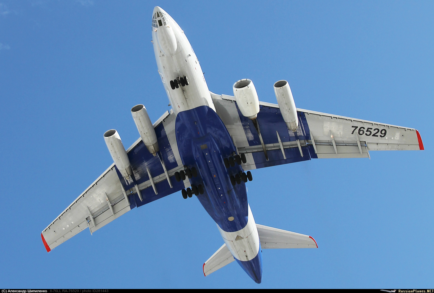
Ilyushin Il-76
073410308
Iraqi Air Force (full Iraqi Airways colours)
The first Il-76 to visit Riem, YI-AIP arrived on 21 May and left on 24 May 1979. It would be followed by other Iraqi Air Force/Iraqi Airways Il-76s: YI-AIO (July 1979), YI-AIM (May 1980), YI-AKQ (February 1982), YI-AKO (April 1982), YI- AKX (April 1982) and YI-ALQ (August 1983). Probably there were more during the mid and late 1980s.
Information from flickr - thanks to Phil Rawlings:
Delivered to the Iraqi Air Force as YI-AIP in September 1977. To Gromov Flight Research Institute as CCCP-76529 in 1989. Became RA-76529 Aeroflot Zhukovsky Flight Research Institute used to test AN-70 Turbofan, at Farnborough Air Show in 1994 and stored 2002 Zhukovsky. Return to service 06.15. Oldest airworthy Il-76 as of 2019.
Registration details for this airframe:
www.scramble.nl/database/soviet/details/85_54380
This airframe as CCCP-76529 at FAB in September 1994 (An-70 turbofan testbed):
www.flickr.com/photos/133813370@N04/50794232853
www.flickr.com/photos/141169709@N06/51185543135
RA-76529 at Zhukovsky in August 1995:
www.flickr.com/photos/pslg05896/30815395322
RA-76529 stored at Zhukovsky in August 2012:
www.flickr.com/photos/ajw1970/8758073033
76529 with Gromov Flight Research Institute at Zhukovsky in January 2016 (bare metal):
cdn.jetphotos.com/full/6/63053_1457811690.jpg

76529 with Gromov Flight Research Institute at Zhukovsky in August 2018 and March 2019:
onespotter.com/photograph/djE6OTQ0OTI5OjEyODB4MS4wOjEwOHg...

onespotter.com/photograph/djE6OTY4MTM5OjEyODB4MS4wOjEwMWg...

russianplanes.net/images/to282000/281443.jpg
Scan from Kodachrome K25 slide (on Kodak Photo CD).
2015 Paris Airshow
F-WWOW Airbus A380-841 Airbus Industrie
27 Apr 2005 Testbed 4x RR Trent 970 Jacques Rosay* FN001
std at TLS 11 Feb 2017 - 29 Jan 2019
"50 Years" sticker May 2019
std at TLS 20 Sep 2019 - 18 Jan 2021
*Jacques Rosay was Vice President Chief Test Pilot of the aircraft manufacturer Airbus. He has piloted the maiden flights of several Airbus airliners, including the A318, A340-500, and A380 Superjumbo. He was born in 1949 in Valréas (Vaucluse), France, and died on 12 June 2015 just 4 days before this picture was taken.
After the accident of CCCP-77111, this aircraft and CCCP-77113 were used as testbed until the Tu-144D model obtained the certificate of airworthiness in the beginning of 80's. As result of 50 trial flights between Moscow and Khabarovsk was recommended to operate with passengers but, unlike Tu-144S, this never happened.
When the Tu-144 program was cancelled, 07-1 was stored at Zhukovsky for almost twenty years until a private German museum bought her by $500,000.
In October 2000 the nose, tail and wings were removed and CCCP-77112 was shipped on a barge for a trip from Moscow to Sinsheim via Baltic sea of more than 4,000 km. The aircraft was re-assembled and on March 2001 lifted to the roof of the museum where today is on display.
This is the only one Tu-144 on display out of Russia.
Maiden Flight: 19th February 1979 : Voronezh, USSR.
Final Flight: 12th November 1981.
Total Flights: 87 flights.
Supersonic Flights:29 flights.
Total Flight Hours: 197 hours, 45 minutes.
Supersonic Flight Hours: 46 hours, 38 minutes.
Current UsageOn display on the roof of the Auto & Technik Museum in Sinsheim, Germany.
Speeding north through Sutton Park with a light-engine move from Derby RTC to Bescot is Network Rail Class 97's, 97304 and 97302, formerly Class 37's, 37217 and 37170, respectively.
The proud and powerful workhorse that even 50 years after its construction, continues to be a major part of the British Rail scene. I am of course talking of one of the most successful diesel locomotives of all time, the Class 37.
In the 1950's, British Rail was in desperate need to replace its ageing fleet of steam locomotives on both freight and passenger usage, and even though the new BR Standard locomotives were starting to make inroads into the Victorian built fleet, it was apparent that diesel and electric haulage was the only way forward. As such, English Electric, who had already had success with the construction of the Class 20 light freight loco and the Class 40 heavy passenger loco, were assigned to help deliver a new mulit-purpose diesel locomotive with a power output of more than 1,500bhp. Although the Class 40 could have been easily capable of handling this task, problems with these locomotives were that it was far too heavy and underpowered, which meant that in addition to hauling a heavy train, it also had the added task of hauling the actual locomotive itself! The earlier Class 40's were especially known for their unreliability, having to be frequently rescued by the steam locomotives they were built to replace!
Essentially, what English Electric did was build a scaled down version of the Class 40, shorter than its predecessor by 8 feet, weighting 33 tons less, and being powered by a much more reliable English Electric 12CSVT engine developing 1,750bhp. A batch of 42 locomotives were delivered in 1960 from the Vulcan Foundry in Newton-le-Willows, these being initially designated English Electric Type 3's, but this order was increased to 309 following the initial success of these engines, with production finishing in 1965. Work on the class was separated between several different plants, with construction primarily taking place at Vulcan Foundry, but also with assistance from Robert Stephenson & Hawthorns factory in Darlington.
The class was initially tasked with both freight and passenger workings, but the rough n' tumble nature of these engines meant they were more at home on goods trains. Some of the earlier locomotives were fitted with Steam Heating Boilers to warm passenger carriages as earlier coaches did not feature Electric Train Heating, although other locomotives had boilers added in 1967/68. Beyond the end of steam in 1968 and throughout the 1970's the Class 37's were dispersed among the many administrative Regions of British Rail, travelling the length and breadth of the country and working all manner of trains from Class 1 Express Passenger services to lower class breakdown trains and short goods services. This became apparent in its variety of liveries, especially following sectorisation of British Rail in the 1980's, with Class 37's sporting the livery of InterCity, Regional Railways and Railfreight Distribution.
Throughout their time however the fleet continued to be interchanged, especially after the introduction of the TOPS computer system which designated them Class 37. The variety of Class 37 sub-classes included:
- Class 37/3: Extended fuel tanks replacing the steam heating boiler
- Class 37/4: Addition of Electric Train Heating for use in passenger service
- Class 37/5: No major changes, a designation for engines with original split headcodes
- Class 37/6: Engines modified for use with Eurostar Class 373 units
- Class 37/7: Heavily modified for heavy freight workings, with extra ballast for more dragging power
- Class 37/9: Used as testbed for experimental Mirrlees MB275T engine
However, as the 1990's drew in and with privatisation on the horizon, it was apparent that the Class 37's were starting to look very tired. Their reliability was starting to falter, and the demands on the class were much greater than before. As such, newly formed primary freight operator EWS, made an order for a new fleet of Class 66 locomotives from General Motors to replace the many ageing British Rail classes. Upon their introduction in 1999, these engines were quick to see off many Class 37's, which went on a variety of their own journeys. In the summer of 2000 and 2001, many Class 37's were exported to France and Spain to help with the construction of their many High Speed Lines, including the LGV Méditerranée route from Lyon to Marseilles. While many of the French ones have since returned, a small fleet of Class 37's continued to work in the sun of Spain on the High Speed route between Perpignan and Figueres, but have since returned upon its opening in 2010.
In 2007, EWS was taken over by DB of Germany to become DB Schenker, which continued to operate a small fleet of Class 37's until 2010 when the last engines were retired. Throughout the 2000's these locomotives were placed into storage and scrapped, this particular era being their darkest hour. But as said, many continued to find their way into new leases of life, their reliable nature and flexible abilities making them a key part of many private fleets.
Direct Rail Services, the former rail arm of British Nuclear Fuels, took on a batch of Class 37's to operate their various freight trains, including the haulage of Nuclear Flasks, a task they continue to do till this day, with 29 of the class still on its books and in regular service. Colas Rail took on a fleet of 4 Class 37's in 2014 to expand their fleet, whilst charter company West Coast Railways owns four and four others were converted for use with Network Rail on engineering services.
Either way, it is apparent that these plucky and powerful little locomotives, of which 48 are preserved and 38 remain in mainline operation, will continue to be an integral part of the British Railway scene for many years to come.
Who knows, maybe they'll live to see mainline service when they're 100!
Airbus A220-300
[Bombardier Aerospace 'CSeries' CS300 (BD-500-1A11)]
MSN 55002
C-FFDO [Airbus S.A.S. livery]
C Series Aircraft Limited Partnership (CSALP)
Copyright © 2018 A380spotter. All rights reserved.
KLGB (Long Beach Airport/Daugherty Field) - 22 SEP 2016
"Boeing One Zero Four" from Boeing Field International Airport (KBFI) landing RWY 12.
Long Beach Airport/Daugherty Field (KLGB) was an intermediate stop for "Boeing 104", with Dallas Love Field (KDAL) being it's final destination on this day, where it would be shown to Southwest Airlines executives.
This is the 4th 737-8 MAX to come off of the assembly line.
Production Site: Renton (RNT)
First Flight: 07 MAY 2016
Test Registration: N8704Q
Hex Code: ABF949
Configuration: Testbed
Engines: 2x CFMI LEAP-1B28
*** Update ***
Delivery to Southwest Airlines: 27 DEC 2017 as N8704Q
Ferried BFI-PHX on 27 DEC 2017 on delivery
Hex Code: ABF949
Fleet Number: 8704
Configuration: Y175
Engines: 2x CFMI LEAP-1B28
Stored at Chicago Midway (MDW) 13 MAR - 18 APR 2019
Stored at Victorville (VCV) 18 APR 2019 - 30 MAR 2021
+++ DISCLAIMER +++
Nothing you see here is real, even though the conversion or the presented background story might be based on historical facts. BEWARE!
Some background:
The Korean People's Army Air and Anti-Air Force began as the "Korean Aviation Society" in 1945. It was organized along the lines of flying clubs in the Soviet Union. In 1946, the society became a military organization and became an aviation division of the Korean People's Army (KPA). It became a branch of the army in its own right in November 1948. The KPAF incorporated much of the original Soviet air tactics, as well as North Korean experience from the UN bombings during the Korean War.
North Korea’s first indigenous jet fighter aircraft, the Wonsan Aircraft Works 여-1 (known as “W-1” outside of the country), started its existence in China as the Shenyang J-3 (Jianjiji = fighter). The J-3 was a project to exploit the knowledge and hardware gained through the license production of the Soviet MiG-15UTI trainer, locally designated JJ-2 (Jianjiji Jiaolianji – fighter trainer), a study that was primarily intended to improve China’s aircraft industry and the country’s respective engineering know how after the Korean War. The Soviet VVS and PVO had been the primary users of the MiG-15 during the Korean war, but not the only ones; it was also used by the PLAAF and KPAF (known as the United Air Army).
The J-3 was designed during the Korean War between 1952 and 1953 and two prototypes were built with Soviet help and tested in 1953, but the aircraft came too late – and it was not regarded as a successor or even an alternative to the Soviet MiG-15, because it lacked modern features like swept wings. The J-3’s design drew more on American rather than British inspiration, having elected to use features such as a very thin (but almost straight) wing akin to the Lockheed P-80 Shooting Star and a basic configuration comparable to the North American F-86 Sabre. Due to its conceptual interceptor role, an emphasis had been placed on a fast rate of climb. Power came from a Klimov VK-1 centrifugal-flow turbojet, a derivative of the British Rolls-Royce Nene Mk.104B that also powered the MiG-15. Armament consisted of four 23 mm (0.906 in) Nudelman-Suranov NS-23 autocannon under the nose.
The J-3’s rate of progress on the project was such that, within 15 months of design work having formally started, the first prototype had been fully constructed. On 28 October 1953, the first J-3 fighter prototype conducted its first flight, even though it still lacked pressurization, armament, and other military equipment. Gradually, new hardware was integrated and tested, and a second aircraft joined the tests in January 1954. Flight tests followed quickly and showed that the J-3 was easy to fly and had exceptional performance and maneuverability for a straight-wing aircraft. Unfortunately, it soon became clear that the laminar flow section used for the original tail unit was totally unsuitable, with extremely severe buffeting setting in at 500 km/h (310 mph). The buffeting was so bad that the test pilots were thrown about in the cockpit, banging their head on the canopy, and the needles fell off all the flight instruments. Fortunately, accidents could be avoided, and the tailplane section was changed with much improved results.
The gun armament caused troubles, too. Firing all four NS-23 at once made the robust engine surge – a problem that did not occur on the MiG-15, but it only carried two of these weapons. A remedy was eventually found through the introduction of a slightly elongated nose that kept the air intake further away from the gun blast shock waves. The flight and test program lasted until 1955, and a total of five J-3 prototypes were built, but with no serious plan to put this aircraft into series production, even more so after China had been offered to produce the even more modern and capable Soviet MiG-17 fighter under license as the J-5. In the People's Republic of China (PRC), an initial MiG-17F was assembled from parts in 1956, with license production following in 1957 at Shenyang. The Chinese-built version was/is known as the Shenyang J-5 (for local use) or F-5 (for export). After this decision, the J-3 program was stopped, but the machines were retained in flightworthy condition as testbeds and chase planes by the PLAAF until the late Sixties
However, this was not the end of the J-3. After fighting had ended on 27 July 1953 when the Korean Armistice Agreement was signed, the Korean People's Army Air and Anti-Air Force (KPAAF) was keen to boost its capabilities and build a domestic aircraft industry, beyond the option to produce existing designs in license. Turning to its main sponsor China, North Korea was offered the plans for the J-3 and its tools, together with a supply of Chinese-built VK-1 engines. Even though the J-3 did not represent the state-of-the-art in jet fighters anymore, it was the best option for an industrial quickstart and until 1956 a dedicated production site for the J-3 was built at Wonsan, leading to the Wonsan Aircraft Works (Wonsan hang-gong-gi jag-eob , 원산 항공기 작업) and its first military product, the 여-1 (Yeo-1 = W-1). When NATO became aware of the aircraft it received the reporting code name “Freshman”.
However, despite the J-3’s plans and tools at hand, the W-1’s production was hampered by the lack of experience, sub-optimal materials, and poor logistics (esp. concerning vital imported components like the Chinese WP-5 engine, a license-built VK-1). Consequently, it took almost three years to roll out the first pre-serial production aircraft in 1959, and even then, the W-1 was plagued with material and reliability problems. Furthermore, once the W-1 became operational in 1961, the aircraft had become outdated. The W-1 had been designed to intercept straight-and-level-flying enemy bombers, not for air-to-air combat (dogfighting) with other fighters. The subsonic (Mach .76) fighter was effective against slower (Mach .6-.8), heavily loaded U.S. fighter-bombers from the Fifties, as well as the mainstay American strategic bombers during the aircraft's development cycle (such as the Boeing B-50 Superfortress or Convair B-36 Peacemaker, which were both still powered by piston engines). It was not however able to intercept the new generation of British jet bombers such as the Avro Vulcan and Handley Page Victor, which could both fly higher. Most W-1s were initially used as night fighters – even though they lacked any on-board radar and the pilot had to rely on visual contact and/or radio guidance from ground stations to make out and close in on a potential target. The USAF's introduction of strategic bombers capable of supersonic dash speeds such as the B-58 Hustler and General Dynamics FB-111 rendered the W-1 totally obsolete in front-line KPAAF service, and they were quickly supplanted by supersonic interceptors such as the MiG-21 and MiG-23.
The rugged aircraft was not retired, though, and found use as ground attack aircraft (despite its limited payload of around 2 tons) and as an advanced fighter trainer. Total production numbers are uncertain, but less than 100 W-1s were produced until 1969, with no further variants becoming known. In 1990, probably forty were still operational, and even after 2000 some KPAAF W-1s were still flying.
General characteristics:
Crew: 1
Length: 10.73 m (35 ft 2 in)
Wingspan: 12.16 m (39 ft 10½ in)
Height: 4.46 m (14 ft 7½ in)
Wing area: 23.8 m² (256 sq ft)
Aspect ratio: 7.3
Empty weight: 4,142 kg (9,132 lb)
Gross weight: 7,404 kg (16,323 lb)
Max takeoff weight: 7,900 kg (17,417 lb)
Powerplant:
1× Wopen WP-5 (Rolls-Royce Nene Mk.104B) centrifugal-flow turbojet
with 26.5 kN (5,950 lbf) thrust
Performance:
Maximum speed: 940 km/h (580 mph, 510 kn) at sea level
Maximum speed: Mach 0.76
Cruise speed: 750 km/h (470 mph, 400 kn)
Maximum Mach number: M0.83
Combat range: 450 km (280 mi, 240 nmi)
Ferry range: 920 km (570 mi, 500 nmi)
Service ceiling: 13,000 m (43,000 ft)
Rate of climb: 38 m/s (7,500 ft/min)
Take-off run: 783 m (2,569 ft)
Landing run: 910 m (2,986 ft)
Armament:
4× 23 mm (0.906 in) Nudelman-Suranov NS-23 autocannon with 100 rounds per gun
2× underwing hardpoints for 2.000 kg of payload, including a variety of unguided iron bombs such
as 2× 250 kg (500 lb) bombs, napalm tanks, pods with unguided missiles, or 2× 350 l (92 US
gal; 77 imp gal) drop tanks for extended range.
The kit and its assembly:
I always thought that the tubby Dassault Ouragan had something “Soviet-ish” about it, looking much like one of the obscure early Yakowlew jet fighter prototypes (e .g. the straight-wing Yak-25 [first use of this designation in 1947] or the swept-wing Yak-30) around 1950. With this idea I had stashed away a Heller Ouragan for a while, and recently wondered about an indigenous North-Korean aircraft that could have emerged after the Korean War? The Ouragan looked like a good basis, and so this project started as a simple conversion of the Heller kit.
While most of the airframe was retained, I made some cosmetic changes to change the aircraft’s looks and add a Warsaw Pact flavor. The characteristic wing tip tanks disappeared, and the wings’ ends were rounded off. The fin tip was extended with a piece of 1.5 mm styrene sheet and a different fin shape was sculpted from it. The original stabilizers were replaced with what I think are stabilizers from a VEB Plasticart 1:100 An-24 – they better match the wing shape than the OOB parts!
The cockpit was taken OOB, I just replaced the ejection seat with a different piece from a KP 1:72 MiG-19. The air intake was modified with the opening from a Heller 1:72 F-84G, extending and narrowing it slightly, even though the internal splitter plate (which also bears the front wheel well) was retained. The landing gear was also basically taken OOB, but the main wheels were now mounted on the outside position (with an adaptation of the covers), and the front wheel was moved 3 mm further forward, to compensate for the slightly longer nose section, and its cover was modified accordingly. The flaps were lowered, primarily because this modification is easy to realize on this kit and it makes the simple aircraft look “livelier”, and the canopy was cut into three parts for open display.
Pylons were added under the wings, together with drop tanks from a Hobby Boss 1:72 MiG-15. The same source provided the swept antenna mast behind the cockpit and the small but characteristic altimeter sensors under the wings. As a final twist of “Sovietization” I added small fences to the wings, made from styrene profiles – they would not be necessary on the aircraft’s straight wings, but they help change the model’s overall look. 😉
Building the Heller Ouragan was a straightforward affair, even though the plastic of the recent re-boxing I used was pretty soft and took long to cure after gluing parts together. A real problem occurred when I tried to close the fuselage halves, though, because the parts did not align well behind the cockpit, as if they were warped? The walls were rather thin, too, and as a result a lot of PSR went into the spine and the ventral area behind the wings, which mismatched badly. The rather thin material in these areas did not help much, either. I have built the Ouragan before, and I do not remember these massive troubles?!
Painting and markings:
I initially considered a North-Korean night fighter camouflage from the Korea War, but since the aircraft would have been introduced into service after the open hostilities, I rather settled for a very dry NMF finish with minimal markings. Therefore, the model received an overall coat with “White Aluminum” from the rattle can and a light overall rubbing treatment with graphite to emphasize the raised panel lines and add a slightly irregular metallic shine to the paint. Since they had disappeared through PSR, I also added/recreated some panel lines with a soft pencil.
The cockpit interior was painted in medium grey and Soviet cockpit turquoise, the landing gear and its wells became metallic-grey (Humbrol 56). The areas around the exhaust and the guns were painted with Revell 91 (Iron), the only color contrasts are red trim tabs.
The large KPAAF roundels with a white background came from a Cutting Edge MiG-15 sheet, the large red tactical code was left over from an unidentifiable “Eastern Bloc” model’s decal sheet. After some more graphite treatment around the guns and the tail section the model was sealed with a coat of semi-gloss acrylic varnish (Italeri), resulting in a nice metallic shine that looks better than expected on this uniform aircraft.
Well, this converted Ouragan looks pretty dull at first sight, due to its simple livery. But this makes it pretty plausible, and the small cosmetic changes add a serious Soviet-esque touch to the aircraft.
C-FJJA
Bombardier Dash 8-Q402
de Havilland Aircraft of Canada
Built 1998
C/N 4001
The prototype transferred from Downsview after the closure of that facility, still used by the new DHC since Oct 2019 as a testbed and demonstrator
This is the first landing of an Airbus A350XWB in Frankfurt. On July 25, 2014 at 18:38h local time F-WWYB has arrived on runway 25C.
MSN 005 has had its first flight on 20.06.14. It is powered by 2x Rolls-Royce Trent XWB turbofans and is currently used as a testbed.
This is flight AIB102 from Iqaluit/Canada.
Please join my Facebook fan page:
www.facebook.com/pages/Thomas-Becker-Aviation-Photography...
...and there is a Plane Spotting group on Facebook you should visit:
www.facebook.com/groups/planespotting/
Flickr has done some major design changes (which I deeply regret). Are you missing collections in Flickr? Me, too!
But they are not lost, just hidden - you can go there by using one of the following links:
Special Aviation Photos
www.flickr.com/photos/thomasbecker/collections/7215762339...
Airlines of the World
www.flickr.com/photos/thomasbecker/collections/7215760571...
Aviation by Date
www.flickr.com/photos/thomasbecker/collections/7215760307...
Airline Alliances of the World
www.flickr.com/photos/thomasbecker/collections/7215762573...
4/2012 - Altoona, PA
Engines dropped into testbed unit NS 1000 are hooked up to the unit's flared SD45 radiators.
Beechcraft Model 18 (or "Twin Beech", as it is also known), Beech 18, built by Beech Aircraft Corporation (USA), s/n 5828 (USAAF reg. 43-35478), École Nationale Aérotechnique (ENA), CF-ZWY-X.
(CYHU) Montreal, St. Hubert, Canada.
HISTORICAL NOTES :
''Beech C-45B Expeditor, USAAF reg. 43-35478 (MSN 5828) to RAF as Expeditor I HB109.
Diverted to RCAF with RAF serial HB109, no RAF service. Redesignated as Expeditor Mk. III. Rebuilt to Mk. 3T standards,
Redesignated Expeditor 3T. Leased to Pratt & Whitney of Canada Jul 12, 1960 as flying testbed for PT-6A turboshaft (nose mounted). Renamed United Aircraftof Canada in 1962. Sold to United Aircraft of Canada Jun 1, 1971 as CF-ZWY. PT-6A removed and airframe given to Ecole Nationale d'Aeronautique, Quebec Jul 1981 as CF-ZXWY-X for use as instructional airframe.
Renamed Musee de l'Air et de l'Espace at Saint Hubert, Canada.''
Former Leeds City Transport and WYPTE Roe bodied Daimler CVG6LX/30 7517 UA was used by Dennis Motors as a testbed for the planned driveline of the Dominator. It was fitted with a Gardner 6LXB engine and Voith automatic gearbox. It was used by SYPTE in Sheffield for several months in 1976.
his is the testbed aircraft for "sustainable bio-fuels" made from animal fats and vegetable waste. It's seen here at Tucson International Airport where test flights are based. Note the #2 engine is very different from the others and that's the one involved in the test.
+++ DISCLAIMER +++
Nothing you see here is real, even though the model, the conversion or the presented background story might be based historical facts. BEWARE!
Some background:
In the aftermath of the Second World War, Sweden required a strong air defense, utilizing the newly developed jet propulsion technology. The original concept had been designed around a mostly straight wing, but after Swedish engineers had obtained German research data on swept-wing designs, the prototype was altered to incorporate a 25° sweep. In order to make the wing as thin as possible, Saab elected to locate the retractable undercarriage in the aircraft's fuselage rather than into the wings.
Extensive wind tunnel testing had also influenced aspects of the aircraft's aerodynamics, such as stability and trim across the aircraft's speed range. In order to test the design of the swept wing further and avoid any surprises, it was decided to modify a Saab Safir. It received the designation Saab 201 and a full-scale swept wing for a series of flight tests. The first 'final' sketches of the aircraft, incorporating the new information, were drawn in January 1946.
The originally envisioned powerplant for the new fighter type was the de Havilland Goblin turbojet engine. However, in December 1945, information on the newer and more powerful de Havilland Ghost engine became available. The new engine was deemed to be ideal for Saab's in-development aircraft, as not only did the Ghost engine had provisions for the use of a central circular air intake, the overall diameter of the engine was favorable for the planned fuselage dimensions, too. Thus, following negotiations between de Havilland and Saab, the Ghost engine was selected to power the type and built in license as the RM 2.
By February 1946 the main outline of the proposed aircraft had been clearly defined. In autumn 1946, following the resolution of all major questions of principal and the completion of the project specification, the Swedish Air Force formally ordered the completion of the design and that three prototype aircraft be produced, giving the proposed type the designation J 29. After a thorough test program, production of the type commenced in 1948 and, in May 1951, the first deliveries of operational production aircraft were received by F 13 Norrköping. The J 29 proved to be very successful and several variants and updates of the Tunnan were produced, including a dedicated reconnaissance variant, a two seat trainer and an all-weather fighter with an onboard radar
However, Sweden foresaw that there would soon be a need for a jet fighter that could intercept bombers at high altitude and also successfully engage fighters. During September 1949, the Swedish Air Force, via the Swedish Defence Material Administration, released a requirement for a cutting-edge interceptor aircraft that was envisioned to be capable of attacking hostile bomber aircraft in the transonic speed range. As released, this requirement specified a top speed of Mach speed 1.4 to 1.5. (1956, the specified speed was revised and raised to Mach 1.7-1.8, and eventually led to the Saab 35 Draken). With the barely supersonic Saab 32 Lansen just under development, and intended for different roles than being a nimble day fighter, the company searched for a way to either achieve supersonic flight through modifications of an existing type or at least gather sufficient data and develop and try the new technologies necessary to meet the 1949 requirements.
Since Sweden did not have a truly supersonic aircraft in its inventory (not even an experimental type), Saab decided to convert the Saab 29 into a supersonic testbed, with the outlook to develop an interim day fighter that could replace the various Tunnan fighter versions and support the new Lansen fleet until a fully capable Mach 1.5+ interceptor was ready for service. Even though the type was regarded as a pure experimental aircraft, the designation remained close to the J29 nomenclature in order to secure military funding for the project and to confuse eventual spies. Consequently, the P29 was initially presented as a new J29 version (hence the “G” suffix).
The P29G was based on a heavily modified production J29B airframe, which was built in two versions and only in two specimens. Work on the first airframe started in 1952, just when the first Saab 32 prototype made its maiden flight. The initial challenge consisted of integrating two relatively compact axial flow jet engines with afterburners into the fuselage, since the J29’s original RM2, even in its late afterburner variant, was not able to safely deliver the necessary thrust for the intended supersonic flight program. After long negotiations, Saab was able to procure a small number of Westinghouse J34-WE-42 turbojets from the USA, which delivered as a pair 40% more thrust than the original RM2B. The engines were only delivered under the restriction that they would exclusively be used in connection with the supersonic research program.
Through a thorough re-construction, the Saab team was able to mount the new engines into the lower rear fuselage, and, internally, the air intake duct had to be modified and forked behind the landing gear wells. Due to the significantly widened rear fuselage, the P29G became quickly nicknamed “Kurviga Tunnan” (= “Curvy Barrel”). Even though the widened rear fuselage increased the aircraft’s frontal cross section, the modified shape had the (unintended) effect of area ruling, a welcome side benefit which became apparent during the flight test and which largely promoted the P29G’s gain of top speed.
Another special and unique feature of the P29G was a special wing attachment system. It consisted of two strengthened, open box spars in the fuselage with additional attachment points along the wing roots, which allowed different wings to be switched with relatively little effort. However, due to this modification, the wing tanks (with a total capacity of 900l inside of the J29s standard wings) were lost and only 2.150l in the Saab 29’s standard fuselage tanks could be carried – but this was, for a research aircraft, not regarded as a major weakness, and compensated for the wing attachment system’s additional weight. The original wing-mounted pitots were replaced by a single, massive sensor boom attached to the aircraft’s nose above the air intake, slightly set-off to starboard in order to give the pilot an unobstructed view.
The first P29G's maiden flight, marked “Gul Urban” (Yellow U), took place in July 1955. The aircraft behaved normally, even though the center of gravity had markedly shifted backwards and the overall gain of weight made the aircraft slightly unstable along the longitudinal axis. During the initial, careful attempts to break the sound barrier, it soon became apparent that both the original wings as well as the original air intake shape limited the P29G's potential. In its original form, the P29G could only barely pass Mach 1 in level flight.
As a consequence, the second P29G, which had been under conversion from another J29B airframe since mid-1954, received more thorough modifications. The air intake was lengthened and widened, and in order to make it more effective at supersonic speed it received a sharp lip. Wind tunnel tests with the first machine led to a modified tail, too: the fin was now taller and further swept back, the stabilizer was moved to a higher position, resulting in a cruciform layout. The original single-piece stabilizer was furthermore replaced by a two-piece, all-moving construction with a 45° sweep and a thinner profile. This not only improved the aerodynamics at high speed, it also suppressed the longitudinal instability problem, even though this was never really cured.
Due to the even higher all-up weight of the new aircraft, the landing gear was reinforced and the 2nd P29G received an experimental suspension system on its main legs with higher spring travel, which was designed for operations on semi-prepared airfields. This system had actually been designed for the updated J29 fighters (esp. the A32B attack variant), but it was not introduced into series production or the Saab 29E/F conversion program. Despite these massive changes, the P29G designation was retained, and the second machine, carrying the tactical code “Röd Urban” (Red U), was quickly nicknamed “Karpen” (“Carp”), due to its characteristic new intake shape, the long fin and its stocky shape.
The second P29G was ready for flight tests in August 1956, just in time to support the Saab 35’s ongoing development – the aircraft, which was eventually built to meet (and exceed) the Swedish Air Force’s 1949 supersonic interceptor requirement. The modifications proved to be successful and the P29G was, fitted with a 60° sweep wing and in clean configuration, able to achieve a maximum speed of 1.367 km/h (849 mph) in level flight, a formidable achievement (vs. the 1,060 km/h (660 mph) of the late J29F and the 1200 km/h (745 mph) of the J32B interceptor) for the post WWII design.
Several wing shapes and profiles were tested, including sweep angles from 25° to 63° as well as different shapes and profiles. Even though the machines carried provisions for the J29’s standard armament, the 20 mm cannons were normally not mounted and replaced with sensors and recording equipment. However, both machines were temporarily fitted with one or two guns in order to analyze the effects of firing the weapons at supersonic speed. Underwing ordnance was also almost never carried. In some tests, though, light bombs or unguided missiles were carried and deployed, or podded cine cameras were carried.
While the second P29G was used for high speed trials, the first machine remained in its original guise and took over low speed handling tests. Thanks to the unique wing switch mechanism, the supersonic research program could be held within a very tight schedule and lasted until late 1959. Thereafter, the P29Gs’ potential was of little use anymore, and the engine use agreement with the USA put an end to further use of the two aircraft, so that both P29Gs were retired from service in 1960. The 1st machine, outfitted with standard J29F wings and stripped off of its engines, remained in use as an instructional air at Malmslätt air base 1969, while the second machine was mothballed. However, both airframes were eventually scrapped in 1970.
General characteristics:
Crew: 1
Length: 11.66 m (38 ft 2 in) fuselage only,
13,97 m (45 ft 9 in) with pitot boom
Wingspan: varied*; 11.0 m (36 ft 1 in) with standard 25° sweep wings,
10.00 m (32 ft 9 ¾ in) with experimental 45° wings
Height: 4.54m (14 ft 10 ½ in)
Wing area: varied*; 24.15 m² (260.0 ft²) with standard 25° sweep wings
22.5 m² (242.2 ft²) with experimental 45° wings
Empty weight: 5,220 kg (11,500 lb)
Max. takeoff weight: 8,510 kg (18,744 lb)
Powerplant:
2× Westinghouse J34-WE-42 turbojets, each rated at 3,400 lbf (15 kN) dry thrust
and 4,200 lbf (19 kN) with full afterburner
Performance:
Maximum speed: 1.367 km/h (849 mph) were achieved*
Range: 790 km (490 mi)
Service ceiling: up to 17,250 m (56,500 ft)*
Rate of climb: up to 45 m/s (8,850 ft/min)*
*Varying figures due to different tested wing configurations
Armament:
None installed; provisions for 4x 20mm Hispano Mark V autocannon in the lower front fuselage.
Depending on the mounted wing type, various external loads could be carried, including a wide range of light bombs, 75 mm (3 in) air-to-air rockets, 145 mm (5.8 in) anti-armor rockets, 150 mm (6 in) HE (high-explosive) rockets or 180 mm (7.2 in) HE anti-ship rockets. Due to the lack of complex wiring or fuel plumbing, no guided weapons or drop tanks could be mounted, though.
The kit and its assembly:
Sweden is a prolific whiffing territory, and the Saab 29 offers some interesting options. This highly modified Tunnan, which is actually rather a kitbashing than a mere model kit modification, is/was a submission to the “More or less engines” group build at whatifmodelers.com in summer 2019.
I actually had the idea of a two-engine J29 in the back of my mind for a long time, spawned by a resin conversion set for the Hasegawa B-47 Stratojet kit that came with new intakes and exhaust sections for the four engine pods. The single engine pod parts had been spent a long time ago, but the twin engine parts were still waiting for a good use. Could the exhaust fit under/into a Tunnan…?
I even had a Matchbox J29 stashed away for this experiment long ago, as well as some donor parts like the wings, and the GB eventually offered the right motivation to put those things together that no one would expect to work.
So I pulled out all the stuff and started – a rather straightforward affair. Work started with the fuselage, which was, together with the (very nice) cockpit assembled OOB at first, the nose filled with as much lead as possible and with the lower rear section cut away, so the B-47 resin jet nozzles would end up at the same position as the original RM2B exhaust. Due to the pen nib fairing between them, though, the profile of the modified tail became (visually) more massive, and I had to fill some gaps under the tail boom (with styrene sheet and putty). The twin engines also turned out to be wider than expected – I had hoped for straight flanks, but the fuselage shape ended up with considerable bulges behind the landing gear wells. These were created with parts from drop tank halves and blended into the rest of the lower hill with PSR work. In the same wake the area under the fin was sculpted and re-created, too.
At that point it became clear that I had to do more on the fuselage, esp. the front end, in order to keep the aircraft visually balance. A convenient solution became an F-100 air intake, which I grafted onto the nose instead of the original circular and round-lipped orifice – with its sharp lip the Super Sabre piece was even a plausible change! The fuselage shapes and diameters differed considerably, though, more PSR became necessary.
Next came the wings: I had already set apart a pair of trapezoid wings with a 45° sweep angle – these were left over from a PM Model Ta 183 conversion some time ago. With their odd shape and size they were a perfect match for my project, even more so due to the fact that I could keep the original J29 wing attachment points, I just had to shorten and modify the trailing edge area on the fuselage. The result was very conclusive.
With the new nose and the wings in place, the overall proportions became clearer: still tail-heavy, but not unpleasant. At this time I was also certain that I had to modify the tail surfaces. The fin was too small and did not have enough sweep for the overall look, and the stabilizer, with its thick profile, rounded edges and the single, continuous rudder did not look supersonic at all. What followed was a long search in the donor banks for suitable replacements, and I eventually came up with a MiG-15 fin (Hobby Boss) which was later clipped at the top for a less recognizable profile. The stabilizers were more challenging, though. My solution eventually became a pair of modified stabilizers from a Matchbox Buccaneer(!), attached to the MiG-15 fin.
The design problems did not stop here, though: the landing gear caused some more headaches. I wanted to keep the OOB parts, but especially the main legs would leave the aircraft with a very goofy look through a short wheelbase and a rear axis position too much forward. In an attempt to save the situation I attached swing arms to the OOB struts, moving the axis maybe 5mm backwards and widening the track by 2mm at the same time. Not much in total, but it helped (a little, even though the aircraft is still very tail-heavy)
As a final addition – since the original, wing-mounted pitots of the J29 were gone now and would not go well with the wing-switching idea – I gave the P29G a large, nose-mounted pitot and sensor boom, placed on top of the nose. This part come, like the air intake, from an F-100.
Painting and markings:
I tend to be conservative when it comes to liveries for what-if models, and the P29G is no exception. At first, I thought that this build could become an operational supersonic daylight interceptor (the J29G), so that I could give the model full military markings and maybe a camouflage paint scheme. However, this idea would not work: the potential real life window for such an aircraft, based on the Saab 29, would be very narrow. And aircraft development in the late Fifties made quantum leaps within a very short period of time: While the J29A entered service, work on the Mach 2 Saab 35 was already underway – nobody would have accepted (or needed) a Mach 1 fighter, based on late Forties technology, at that time anymore, and there was the all-weather Saab J32B around, too. The update program with new wings and a more powerful afterburner engine was all that could be done to exploit the Tunnan’s potential, resulting in the (real world’s) J29E and F variants.
I eventually decided that the J29G would only be a prototype/research aircraft, consequently called P29G, and through this decision I became more or less settled upon a NMF finish with some colorful markings. Consequently, the model was painted with various shades of metal colors, primarily Polished Aluminum Metallizer from Humbrol, but also with Humbrol 191 and Matt Aluminum Metallizer as well as ModelMaster Steel Metallizer. Around the exhaust section, I also used Revell 91 (Iron) and ModelMaster Exhaust Metallizer. Some single panels and details were painted with Revell 99 (Aluminum), and I also used generic decal material in silver to simulate some smaller access panels. Grey decal sheet was used to simulate covers for the cannon nozzles.
The cockpit interior was painted, according to Saab 29 standard, in a dark greenish-grey (Revell 67), and bluish grey was used inside of the landing gear wells (Revell 57). The pitot boom received black and white stripes.
For markings I let myself get inspired from the real world Saab 29 and 32 prototypes, which were all marked with a colored “U” tactical code on the fin and also on the front fuselage, simply meaning “Utverding” (= “Test”). I found four red decals, and I also gave the aircraft a yellow cheatline, lent from an Airfix F-86D decal sheet. The Swedish roundels come from a generic aftermarket sheet, most stencils were taken from the Revell OOB sheet and a Printscale J29 sheet.
Before the model was sealed with semi-gloss acrylic varnish from Italeri, some grinded graphite was rubbed onto the rear fuselage, adding a metallic shine and simulating exhaust stains.
A thorough conversion – this has rather evolved into a kitbashing than just a kit conversion: not much from the original Matchbox J29 has been left over. But I like the outcome, even though things developed gradually from the simple idea of changing the number of engines on the Tunnan. One thing led to another. The resulting aircraft looks quite plausible, even though I am not totally happy with the landing gear, which appears to be rather far forward, despite surgical measures to mend the situation. The Ta 183 wings are a very good match, though, and I cannot help but recognize a certain French look, maybe due to the cruciform tail and the oval air intake? The P29G could also, with Argentinian marking, have become a revised version of the FMA Pulqui II?
In 1961, the testbed aircraft Ye-7SPS demonstrated a flap-blowing system where the air is forced over the flap surface to increase stability at lower air speeds. This system found its way onto the MiG-21PFS (Model 94; NATO reporting name: “Fishbed-D/F”). The first nine production batches of the MiG-21PFS (Fishbed-D/F) were externally identical to the MiG-21PF (Fishbed-D) but with blown flaps and a brake chute fairing at the fin’s base. From batches 10 to 19, the large chord vertical stabilizer first seen on the MiG-21FL (Fishbed-D) was introduced, but the aircraft retained the SK ejection seat and one piece, the forward-opening canopy of the MiG-21PF. From batch 20 onwards, the MiG-21PFS aircraft had a wide-chord tail, a KM-1 ejection seat and a two-piece, sideways-opening canopy.
In this image, a later batch MiG-21PFS (Fishbed-F) flying with the 85th Guards Fighter Aviation Regiment unloads its UB-16-57U rocket launcher. You can see the larger tail fin and the sideways-opening canopy (barely). This model has functioning flaps and speed brakes open on this attack run. The forward speed brakes were fitted when the cannons were removed, and additional fuel tanks were inserted.
Some background:
The VF-1 was developed by Stonewell/Bellcom/Shinnakasu for the U.N. Spacy by using alien Overtechnology obtained from the SDF-1 Macross alien spaceship. Its production was preceded by an aerodynamic proving version of its airframe, the VF-X. Unlike all later VF vehicles, the VF-X (sometimes referred to as VF-X1) was strictly a conventional/non-transformable jet aircraft, even though it incorporated many structural components and several key technologies that were vital for the transformable VF-1’s successful development that ran in parallel. Therefore, the VF-X was never intended as an air superiority fighter, but rather a flight-capable analogue test bed and proof of concept for the VF-1’s basic layout and major components. In this role, however, the VF-X made vital contributions to systems’ development that were later incorporated into the VF-1’s serial production and sped the program up considerably.
VF-X production started in early 2006, with four airframes built. The flight tests began in February 2007. The first prototype (“01”) was piloted and evaluated by ace pilot Roy Fokker, in order to explore the aircraft’s flight envelope, general handling and for external stores carriage tests. The three other VF-Xs successively joined the test program, each with a different focus. “02” was primarily tasked with the flight control and pilot interface program, “03” was allocated to the engine, vectoring thrust and steering systems development, and “04” was primarily involved in structural and fatigue tests.
In November 2007, the successful VF-X tests and the flights of the VF-X-1 (the first fully transformable VF-1 prototype, which had been under construction in parallel to the VF-X program) led to formal adoption of the “Valkyrie” variable fighter by the United Nations Government.
The space-capable VF-1's combat debut was on February 7, 2009, during the Battle of South Ataria Island - the first battle of Space War I - and remained the mainstay fighter of the U.N. Spacy for the entire conflict.
Introduced in 2008, the VF-1 proved to be an extremely capable craft, successfully combating a variety of Zentraedi mecha, even in most sorties which saw UN Spacy forces significantly outnumbered. The versatility of the Valkyrie design enabled the variable fighter to act as both large-scale infantry and as air/space superiority fighter. The signature skills of U.N. Spacy ace pilot Maximilian Jenius exemplified the effectiveness of the variable systems as he near-constantly transformed the Valkyrie in battle to seize advantages of each mode as combat conditions changed from moment to moment.
The basic VF-1 was deployed in four sub-variants (designated A, D, J, and S) and its success was increased by continued development of various enhancements. These included the GBP-1S "Armored Valkyrie” external armor and infantry weapons pack, so-called FAST Packs for "Super Valkyries” for orbital use, and the additional RÖ-X2 heavy cannon pack weapon system for the VF-1S “Strike Valkyrie” with additional firepower.
After the end of Space War I, the VF-1 continued to be manufactured both in the Sol system and throughout the UNG space colonies. Although the VF-1 would eventually be replaced as the primary Variable Fighter of the U.N. Spacy by the more capable, but also much bigger, VF-4 Lightning III in 2020, a long service record and continued production after the war proved the lasting worth of the design.
The VF-1 was without doubt the most recognizable variable fighter of Space War I and was seen as a vibrant symbol of the U.N. Spacy even into the first year of the New Era 0001 in 2013. At the end of 2015 the final rollout of the VF-1 was celebrated at a special ceremony, commemorating this most famous of variable fighters. The VF-1 Valkryie was built from 2006 to 2013 with a total production of 5,459 VF-1 variable fighters with several variants (VF-1A = 5,093, VF-1D = 85, VF-1J = 49, VF-1S = 30, VF-1G = 12, VE-1 = 122, VT-1 = 68), and several upgrade programs were introduced.
The fighter remained active in many second line units and continued to show its worthiness years later, e. g. through Milia Jenius who would use her old VF-1 fighter in defense of the colonization fleet - 35 years after the type's service introduction.
General characteristics:
Accommodation: One pilot in a Marty & Beck Mk-7 zero/zero ejection seat
Length 14.23 meters
Wingspan 14.78 meters (at 20° minimum sweep)
Height 3.84 meters
Empty weight: 13.25 metric tons
Standard T-O mass: 18.5 metric tons
Power Plant:
2x Shinnakasu Heavy Industry/P&W/Roice FF-2001 thermonuclear reaction turbine engines, output 650 MW each, rated at 11,500 kg in standard or in overboost (225.63 kN x 2)
4 x Shinnakasu Heavy Industry NBS-1 high-thrust vernier thrusters (1 x counter reverse vernier thruster nozzle mounted on the side of each leg nacelle/air intake, 1 x wing thruster roll control system on each wingtip);
Performance:
Top speed: Mach 2.71 at 10,000 m; Mach 3.87 at 30,000+ m
Thrust-to-weight ratio: empty 3.47; standard T-O 2.49; maximum T-O 1.24
Armament:
None installed, but the VF-X had 4x underwing hard points for a wide variety of ordnance, plus a ventral hardpoint for a Howard GU-11 55 mm three-barrel Gatling gun pod with 200 RPG, fired at 1,200 rds/min or other stores like test instruments
The model and its assembly:
Another submission to the “Prototypes” group build at whatifmodelers.com in July 2020. Being a VF-1 fan (and have built maybe twenty o these simple Arii kits), adding a VF-X was, more or less, a must – even more so because I had a suitable Valkyrie Fighter kit at hand for the conversion. As a side note, I have actually built something quite similar from a VF-1D many years ago: a fictional, non-transformable advanced trainer, without knowing about the VF-X at all.
Thanks to the “Macross - Perfect Memory” source book, the differences between the transformable VF-1 and its early testbed were easy to identify:
- Fixed legs with faired ducts from the intakes on (thighs)
- Ankle recesses disappeared
- Less and slightly different panel lines on the back and on the nose
- ventral head unit deleted and a respective fairing installed instead
- Levelled underside (shoulder fairings of the folded arms were cut down)
- Leg attachment points on the nose deleted
- No small, circular vernier thrusters all around the hull
- Some new/different venting grills (created mostly with 0.5mm black decal stripes)
Beyond the changes, the VF-1A was basically built OOB. Thankfully, the VF-X already features the later VF-1’s vectored thrust nozzles/feet, so that no changes had to be made in this respect. A pilot figure was added to the cockpit for the beauty pics, and after the flight scenes had been shot, the canopy remained open on a swing arm for static display. For the same reason, the model was built with the landing gear extended.
As a test aircraft, the underwing pylons and their AMM-1 ordnance were left away and the attachment points hidden with putty. I also omitted the ventral gun pod and left the aircraft clean. However, for the flight scene pictures, I implanted an adapter for a display holder made from wire.
In order to emphasize the test vehicle character of the VF-X, I gave the model a scratched spin recovery parachute installation between the fins, using a real world F-22 testbed as benchmark. It consists of styrene profiles, quite a delicate construction. For the same reason I gave the VF-X a long sensor boom on the nose, which changes the Valkyrie’s look, too. Finally, some small blade antennae were added to the nose and to the spine behind the cockpit.
Painting and markings:
To be honest, I have no idea if there was only a single VF-X prototype in the Macross universe, or more. Just one appears in the TV series in episode #33, and lack of suitable information and my personal lack of Japanese language proficiency prevents any deeper research. However, this would not keep me from inventing a personal interpretation of the canonical VF-X, especially because I do not really like the original livery from the TV series: an overall light grey with some simple black trim and “TEST” written on the (fixed) legs. Yamato did an 1:60 scale toy of the VF-X, but it was/is just a VF-1 with a ventral fairing; they added some shading to the basic grey – but this does not make the aircraft more attractive, IMHO.
When I looked at the original conceptual drawing of the VF-X in the “Macross - Perfect Memory” source book, however, I was immediately reminded of the F-15 prototypes from the Seventies (and this program used a total of twelve machines!). These featured originally a light grey (FS 36375?) overall base, to which bright dayglo orange markings on wings, fins and fuselage were soon added – in a very similar pattern to the VF-X. I think the VF-X livery was actually inspired by this, the time frame matches well with the production of the Macross TV series, too, and that’s what I adapted for my model.
In order to come close to the F-15 prototype livery, I gave “my” VF-X an overall basic coat of RAL 7047 “Telegrau 4”, one of German Telekom’s corporate colors and a very pale grey that can easily be mistaken for white when you do not have a contrast reference.
The cockpit received a medium grey finish, the ejection seat became black with brown cushions; the pilot figure is a 1:100 seated passenger from an architecture supplies, painted like an early VF-1 pilot in a white/blue suit. The jet nozzles/feet were painted with Revell 91 (Iron) and later treated with grinded graphite for a more metallic finish. The landing gear became classic white (I used Revell 301, which is a very pure tone, as contrast to the RAL 7047 on the hull), the air intake ducts and the internal sections of the VG wings were painted with dark grey (Revell 77).
For some diversity I took inspiration from the Yamato VF-X toy and added slightly darker (Humbrol 166, RAF Light Aircraft Grey) areas to the hull and the legs. Next, the panel lines were emphasized through a thinned black ink wash, but I did no panel post shading so that the VF-X would not look too dirty or worn.
Onto this basis I applied the orange dayglo markings. On the wings and fins, these were painted – they were applied with spray paint from a rattle can, involving lots of masking. The leading edges on wings and fins were created with grey decal sheet material, too. At this stage, some surface details and more fake panel lines were added with a soft pencil.
The orange cheatline under the cockpit is a personal addition; I found that some more orange had to be added to the nose for visual balance, and I eventually went for the simple, trimmed stripe (TL Modellbau material) instead of trying to apply decal sheet material around the jagged air intakes (F-15 prototype style). The black “TEST”, “VFX” and “U.N. Spacy” markings were designed at the computer and printed on clear inkjet decal paper. Even though the “real” VF-X does not feature the UNS “kite” insignia, I decided to add them to the model. These come from the OOB sheet, which also provided most (slightly yellowed) stencils.
Finally, the model was sealed with a coat of matt acrylic varnish (Italeri).
A rather different VF-1 project (and it is – to my astonishment – #28 in my 1:100 VF-1 Fighter mode collection!!!), with more changes to the basic model kit than one might expect at first sight. VF-X and VF-1 differ considerably from each other, despite identical outlines! However, I like the outcome, and I think that going a different route from the canonical grey/black livery paid out, the bright orange markings really make this VF-X stand out, and it looks IMHO more like a testbed than the “real” aircraft from the TV series.
Taken from; North Galiano, British Columbia, Canada,
Trincomali Channel, Gulf Islands, British Columbia, Canada.
Airframe Family: Beech 18 Expeditor / AT-7 / AT-11 / C-45 / JRB / SNB
Latest Model:Expeditor 3T
Last Military Serial:1418 RCAF
Construction Number:8041
Last Civil Registration:C-FKAK
Latest Owner or Location:Pacific Seaplanes Inc, Cedar, BC
For my video; youtu.be/bDmLHoMDllM
Year: 1944 Serial Number: Beech c/n 8041, AAF 44-47633, RCAF 1418
Engine(s): P&W R985, 9-Cyl. Radials, 450-HP each
The Beechcraft Model 18 (or "Twin Beech", as it is also known) is a 6- to 11-seat, twin-engined, low-wing, tailwheel light aircraft manufactured by the Beech Aircraft Corporation of Wichita, Kansas. Continuously produced from 1937 to November 1969 (over 32 years, a world record at the time), over 9,000 were built, making it one of the world's most widely used light aircraft. Sold worldwide as a civilian executive, utility, cargo aircraft, and passenger airliner on tailwheels, nosewheels, skis, or floats, it was also used as a military aircraft.
During and after World War II, over 4,500 Beech 18s were used in military service—as light transport, light bomber (for China), aircrew trainer (for bombing, navigation, and gunnery), photo-reconnaissance, and "mother ship" for target drones—including United States Army Air Forces (USAAF) C-45 Expeditor, AT-7 Navigator, and AT-11 Kansan; and United States Navy (USN) UC-45J Navigator, SNB-1 Kansan, and others. In World War II, over 90% of USAAF bombardiers and navigators trained in these aircraft.
In the early postwar era, the Beech 18 was the pre-eminent "business aircraft" and "feeder airliner". Besides carrying passengers, its civilian uses have included aerial spraying, sterile insect release, fish seeding, dry-ice cloud seeding, aerial firefighting, air-mail delivery, ambulance service, numerous movie productions, skydiving, freight, weapon- and drug-smuggling, engine testbed, skywriting, banner towing, and stunt aircraft. Many are now privately owned, around the world, with 240 in the U.S. still on the FAA Aircraft Registry in August 2017
Moscow. July 2009
All-Russian Exhibition Centre (Всероссийский выставочный центр) is a permanent general-purpose trade show in Moscow, Russia.
The "All-Russia Exhibition Centre" is a state joint-stock company, officially abbreviated as GAO "VVC", which stands for "Gosudarstvennoye Aktsionernoye Obshchestvo 'Vserossiyskiy Vystavochny Centr'".
VVC is a member of exhibition associations: IUEF (since 1991) and UFI (since 1997).
History
1935-1939 Construction
This section is based on Soviet public documents, available in Russian at www.bcxb.ru
The exhibition was established February 17, 1935 as the All-Union Agricultural Exhibition (VSKhV) (Russian: Всесоюзная Сельско-Хозяйственная Выставка Vsesoyuznaya Selsko-Khozyaystvennaya Vystavka). Existing site (then known as Ostankino Park, a country territory recently incorporated into city limits), was approved in August, 1935. Master plan by Vyacheslav Oltarzhevsky was approved in April, 1936, and the first show season was announced to begin in July, 1937.
However, plans didn't materialize, and 3 weeks before the deadline Stalin personally postponed the exhibition by one year (to August 1938). It seemed that this time everything would be ready on time, and again the builders failed to complete their work, and regional authorities failed to select and deliver proper exhibits. Some pavilions and the 1937 entrance gates by Oltarzhevsky were torn down to be replaced with more appropriate structures (most pavilions were criticized for having no windows). According to Oltarzhevsky's original plan, all of the pavilions were to be constructed from wood. In 1938, a government commission examined the construction and decided that it did not suit the ideological direction of the moment. The exhibition was considered too modest and too temporary. Oltarzhevsky was arrested, together with the Comissar for Agriculture and his staff, and eventually released in 1943. Later, he worked on the 1947-1953 Moscow skyscraper project.
As a result, in August 1938 Nikita Khrushchev, speaking at the Supreme Soviet assembly, declared that the site is not ready, and the opening was extended to August, 1939. It opened indeed August 1, 1939, and worked in 8AM - 11PM mode until October 25 (40,000 daily attendance). 1940 and 1941 seasons followed; after the German invasion, July 1, 1941 the exhibition was closed - until the end of World War II.
1948-1959 Renovation
Statue by Vera Mukhina over the northern entrance to the VDNKHIn October, 1948 the State ordered to renew the Exhibition, starting with the 1950 season. Again, the opening was postponed more than once; the first post-war season opened in 1954 (still as Agricultural exhibition). In 1956 season the planners set aside an Industrial area within the main territory; more restructuring and rebuilding followed. In 1959 the park was renamed Exhibition of Achievements of the National Economy (Russian: Выставка Достижений Народного Хозяйства Vystavka Dostizheniy Narodnovo Khozyaystva) or ВДНХ/VDNKh.
Space pavillon, 1980By 1989 the exhibition had 82 pavilions with the exhibition area of 700,000 square metres. Each pavilion (including the 1939 "regions") had been dedicated to a particular industry or a field: the Engineering Pavilion (1954), the Space Pavilion (1966), the Atomic Energy Pavilion (1954), the People's Education Pavilion (1954), the Radioelectronics Pavilion (1958), the Soviet Culture Pavilion (1964).
During the Soviet times, each year VDNKh hosted more than 300 national and international exhibitions and many conferences, seminars and meetings of scientists and industry professionals. These events attracted about 11 million visitors annually, including 600,000 guests from outside the Soviet Union. The "Radioelectronics" exhibition hall for some years housed the working (and unique) prototypes of the most advanced ES EVM computers to date, which were time-shared by many research organizations right on the premises.
The most memorable feature of the exhibition site was the statue Worker and Kolkhoz Woman (Rabochiy i Kolkhoznitsa), featuring the gigantic figures of a man and woman holding together the famous "hammer and sickle". The sculpture, which reaches 25 meters toward the sky, was created by Vera Mukhina and originally crowned the 35-meter-tall Soviet pavilion at the Exposition Internationale des Arts et Techniques dans la Vie Moderne (1937). The statue was featured on a logo of Mosfilm, Russia's largest movie studio.
[edit] Present Day
Space Pavilion. The Tupolev Tu-154 (reg. no. SSSR-85005, prod. no. 70M005, 1970 year of production, Model 005) in front of the pavilion was dismantled on September 14, 2008. This Tupolev Tu-154 was used as a flight testbed.In 1992, VDNKh was renamed, receiving its current name VVC. It occupies 2,375,000 square metres of which 266,000 square metres are used for indoor exhibits. The territory of VVC is greater than that of the Principality of Monaco and has approximately 400 buildings. Inadequate maintenance of Vera Mukhina's statue caused such disrepair that the statue was disassembled (see 2006 photographs of what's left). It was slated to be refurbished and installed on the top of the new pavilion by 2008[1], but funding shortages lead to dragged-out restoration. Now it is to be installed back by the end of 2010.
The term "VDNKh" is still in use, including the name of a nearby subway station.
Wikipedia
KTUS.
Tucson, AZ.
9-30-25.
Photo by: Ned Harris.
Note: The 18 minute flight to Pinal Airpark was likely the final flight of this aircraft.
The C111 was a series of experimental automobiles produced by Mercedes-Benz in the 1960s and 1970s.
The company was experimenting with new engine technologies, including Wankel engines, Diesel engines, and turbochargers, and used the basic C111 platform as a testbed. Other experimental features included gullwing doors and a luxurious interior with leather trim and air conditioning.
The first version of the C111 was completed in 1969. It used a fiberglass body shell and had a three-rotor direct fuel injected Wankel engine mounted in the middle. The next C111 appeared in 1970. It used a four-rotor engine producing 370 hp (275 kW). The car could reportedly hit 290 km/h (180 mph).
The company decided not to adopt the Wankel engine and turned to Diesel experiments for the third C111. With its 230 horsepower (170 kW)@ 4,400-4,600 5-speed manual straight-5 turbo-Diesel, the C111 broke nine diesel and gas speed records. With more aerodynamic bodywork that gave it an air drag coefficient of an incredible .191, the C111 eventually hit 200 mph (322 km/h) at Nardò in 1978, and averaged 14.7mpg@ 316 km/h (195.4 mph) over a 12 hour cruise. A later 500 hp (372 kW) 4.8 L twin KKK-turbocharged V8 version set another record, with an average lap-speed of 403.78 km/h (250.958 mph). It was achieved by Dr. Hans Leibold in 1 minute, 56.67 seconds on May 5, 1979.