View allAll Photos Tagged control_systems
Ntelligent networks in Tampa, Florida provide the best physical access control solution to protect your assets and networks. It is a great security technique to monitor the resources in a computing environment. Get to know more visit our website today. Ntelligent Networks | www.ntelligentnetworks.com/access-control-tampa-fl/
From the Command Zone advanced electronics and control system, Side Roll and Frontal Air Bag protection, TAK-4 Independent Front Suspension, Air-Actuated Steps, Deck Monitor, not to mention Night Scan Telescoping Light Tower, the Pierce Quantum is the proud choice of HCDF.
1:50 TWH Collectibles:
Pierce Quantum Pumper
Engine 11
Henrico County Division of Fire
County of Henrico,
Commonwealth of Virginia, USA
#1stPixTWH
#1stPixDioramasXL
Olympus OM-D E-M5 Mark III
Olympus M.14-42mm F3.5-5.6 II R
For more info about the dioramas, check out the FAQ: 1stPix FAQ
1stPix Dioramas Instagram: 1stPix Dioramas on Instagram
1stPix Dioramas Facebook: 1stPix Dioramas Facebook
1stPix YouTube: 1stPix Dioramas on YouTube
1stPix Dioramas on Twitter: @1stPixDioramas
See more photos of this, and the Wikipedia article.
Details, quoting from Smithsonian National Air and Space Museum | Space Shuttle Enterprise:
Manufacturer:
Rockwell International Corporation
Country of Origin:
United States of America
Dimensions:
Overall: 57 ft. tall x 122 ft. long x 78 ft. wing span, 150,000 lb.
(1737.36 x 3718.57 x 2377.44cm, 68039.6kg)
Materials:
Aluminum airframe and body with some fiberglass features; payload bay doors are graphite epoxy composite; thermal tiles are simulated (polyurethane foam) except for test samples of actual tiles and thermal blankets.
The first Space Shuttle orbiter, "Enterprise," is a full-scale test vehicle used for flights in the atmosphere and tests on the ground; it is not equipped for spaceflight. Although the airframe and flight control elements are like those of the Shuttles flown in space, this vehicle has no propulsion system and only simulated thermal tiles because these features were not needed for atmospheric and ground tests. "Enterprise" was rolled out at Rockwell International's assembly facility in Palmdale, California, in 1976. In 1977, it entered service for a nine-month-long approach-and-landing test flight program. Thereafter it was used for vibration tests and fit checks at NASA centers, and it also appeared in the 1983 Paris Air Show and the 1984 World's Fair in New Orleans. In 1985, NASA transferred "Enterprise" to the Smithsonian Institution's National Air and Space Museum.
Transferred from National Aeronautics and Space Administration
• • •
Quoting from Wikipedia | Space Shuttle Enterprise:
The Space Shuttle Enterprise (NASA Orbiter Vehicle Designation: OV-101) was the first Space Shuttle orbiter. It was built for NASA as part of the Space Shuttle program to perform test flights in the atmosphere. It was constructed without engines or a functional heat shield, and was therefore not capable of spaceflight.
Originally, Enterprise had been intended to be refitted for orbital flight, which would have made it the second space shuttle to fly after Columbia. However, during the construction of Columbia, details of the final design changed, particularly with regard to the weight of the fuselage and wings. Refitting Enterprise for spaceflight would have involved dismantling the orbiter and returning the sections to subcontractors across the country. As this was an expensive proposition, it was determined to be less costly to build Challenger around a body frame (STA-099) that had been created as a test article. Similarly, Enterprise was considered for refit to replace Challenger after the latter was destroyed, but Endeavour was built from structural spares instead.
Service
Construction began on the first orbiter on June 4, 1974. Designated OV-101, it was originally planned to be named Constitution and unveiled on Constitution Day, September 17, 1976. A write-in campaign by Trekkies to President Gerald Ford asked that the orbiter be named after the Starship Enterprise, featured on the television show Star Trek. Although Ford did not mention the campaign, the president—who during World War II had served on the aircraft carrier USS Monterey (CVL-26) that served with USS Enterprise (CV-6)—said that he was "partial to the name" and overrode NASA officials.
The design of OV-101 was not the same as that planned for OV-102, the first flight model; the tail was constructed differently, and it did not have the interfaces to mount OMS pods. A large number of subsystems—ranging from main engines to radar equipment—were not installed on this vehicle, but the capacity to add them in the future was retained. Instead of a thermal protection system, its surface was primarily fiberglass.
In mid-1976, the orbiter was used for ground vibration tests, allowing engineers to compare data from an actual flight vehicle with theoretical models.
On September 17, 1976, Enterprise was rolled out of Rockwell's plant at Palmdale, California. In recognition of its fictional namesake, Star Trek creator Gene Roddenberry and most of the principal cast of the original series of Star Trek were on hand at the dedication ceremony.
Approach and landing tests (ALT)
Main article: Approach and Landing Tests
On January 31, 1977, it was taken by road to Dryden Flight Research Center at Edwards Air Force Base, to begin operational testing.
While at NASA Dryden, Enterprise was used by NASA for a variety of ground and flight tests intended to validate aspects of the shuttle program. The initial nine-month testing period was referred to by the acronym ALT, for "Approach and Landing Test". These tests included a maiden "flight" on February 18, 1977 atop a Boeing 747 Shuttle Carrier Aircraft (SCA) to measure structural loads and ground handling and braking characteristics of the mated system. Ground tests of all orbiter subsystems were carried out to verify functionality prior to atmospheric flight.
The mated Enterprise/SCA combination was then subjected to five test flights with Enterprise unmanned and unactivated. The purpose of these test flights was to measure the flight characteristics of the mated combination. These tests were followed with three test flights with Enterprise manned to test the shuttle flight control systems.
Enterprise underwent five free flights where the craft separated from the SCA and was landed under astronaut control. These tests verified the flight characteristics of the orbiter design and were carried out under several aerodynamic and weight configurations. On the fifth and final glider flight, pilot-induced oscillation problems were revealed, which had to be addressed before the first orbital launch occurred.
On August 12, 1977, the space shuttle Enterprise flew on its own for the first time.
Preparation for STS-1
Following the ALT program, Enterprise was ferried among several NASA facilities to configure the craft for vibration testing. In June 1979, it was mated with an external tank and solid rocket boosters (known as a boilerplate configuration) and tested in a launch configuration at Kennedy Space Center Launch Pad 39A.
Retirement
With the completion of critical testing, Enterprise was partially disassembled to allow certain components to be reused in other shuttles, then underwent an international tour visiting France, Germany, Italy, the United Kingdom, Canada, and the U.S. states of California, Alabama, and Louisiana (during the 1984 Louisiana World Exposition). It was also used to fit-check the never-used shuttle launch pad at Vandenberg AFB, California. Finally, on November 18, 1985, Enterprise was ferried to Washington, D.C., where it became property of the Smithsonian Institution.
Post-Challenger
After the Challenger disaster, NASA considered using Enterprise as a replacement. However refitting the shuttle with all of the necessary equipment needed for it to be used in space was considered, but instead it was decided to use spares constructed at the same time as Discovery and Atlantis to build Endeavour.
Post-Columbia
In 2003, after the breakup of Columbia during re-entry, the Columbia Accident Investigation Board conducted tests at Southwest Research Institute, which used an air gun to shoot foam blocks of similar size, mass and speed to that which struck Columbia at a test structure which mechanically replicated the orbiter wing leading edge. They removed a fiberglass panel from Enterprise's wing to perform analysis of the material and attached it to the test structure, then shot a foam block at it. While the panel was not broken as a result of the test, the impact was enough to permanently deform a seal. As the reinforced carbon-carbon (RCC) panel on Columbia was 2.5 times weaker, this suggested that the RCC leading edge would have been shattered. Additional tests on the fiberglass were canceled in order not to risk damaging the test apparatus, and a panel from Discovery was tested to determine the effects of the foam on a similarly-aged RCC leading edge. On July 7, 2003, a foam impact test created a hole 41 cm by 42.5 cm (16.1 inches by 16.7 inches) in the protective RCC panel. The tests clearly demonstrated that a foam impact of the type Columbia sustained could seriously breach the protective RCC panels on the wing leading edge.
The board determined that the probable cause of the accident was that the foam impact caused a breach of a reinforced carbon-carbon panel along the leading edge of Columbia's left wing, allowing hot gases generated during re-entry to enter the wing and cause structural collapse. This caused Columbia to spin out of control, breaking up with the loss of the entire crew.
Museum exhibit
Enterprise was stored at the Smithsonian's hangar at Washington Dulles International Airport before it was restored and moved to the newly built Smithsonian's National Air and Space Museum's Steven F. Udvar-Hazy Center at Dulles International Airport, where it has been the centerpiece of the space collection. On April 12, 2011, NASA announced that Space Shuttle Discovery, the most traveled orbiter in the fleet, will be added to the collection once the Shuttle fleet is retired. When that happens, Enterprise will be moved to the Intrepid Sea-Air-Space Museum in New York City, to a newly constructed hangar adjacent to the museum. In preparation for the anticipated relocation, engineers evaluated the vehicle in early 2010 and determined that it was safe to fly on the Shuttle Carrier Aircraft once again.
Very little is known about the Gundrarian Conglomerate. It is a very secretive faction within the galaxy, allowing almost no trade or travel within its borders. No military vessels belonging to another faction are known to have ever travelled into Gundrarian space and come out.
A Vamyr battle flotilla is known to have entered a Gundrarian-controlled system, but the Confederate scout ships reported none had exited. When any trade is made with the Gundrarian Conglomerate, it is usually for exceedingly rare items or materials, which are then put onto unmanned ships and sent into Conglomerate space, where they are never seen or heard from again. The Gundrarians always pay in full, upfront, for the enitre cargo AND the ship it is sent on. No one has yet to try and renege or cheat on a contract with the Gundrarian Conglomerate.
Consequently, what is known about the Traveler-class heavy frigate is known only through careful observation, mostly by the Confederation Of Republic Systems and the Royal Empire, both of which border the few systems occupied by the Gundrarian Conglomerate. Although sized like a destroyer, it has very few visible weapons, and so was classified as a heavy frigate. It was known to be very fast, however the strength of its defenses were not well known until the Skirmish at Adriak.
A wealthy trading outpost, Adriak was the site of a massive Vamyr attack, a full battle fleet intent on ransacking the outpost and destroying it, weaking the economic ties it had to the rest of the galaxy. A single Traveler was in-system, negotiating for a trade agreement, when the attack happened. By chance, two small battle groups, one each from the Royal Empire and the Confederation of Republic Systems, were conducting a military exercise in the system. They moved to engage the Vamyr ships and allow all civilian and private craft a chance to escape. However, they were too far away, and the Vamyr started opening fire, destroying everything in site, including the Adrika-1 space station, the lifeblood of the system. The sole Traveler-class, apparently to protect the fleeing civilian vessels, hung back, attracting the fire of the Vamyr ships.
It sustained a tremendous amount of firepower, more than even a larger ship than it with full power to shields should have been able to withstand, and did so for far longer than it should have, until the Allied ships came to the rescue, allowing it to escape. After the battle, with the Vamyr refusing to pay compensations, the Gundrarians offered to pay to rebuild the Adrika-1 for a discount on future trade agreements. The Adriak system's government readily agreed.
The Traveler-class is the only known Gundrarian ship type, and no Traveler has ever been observed to commit acts of aggression. While the peace between the Gundrarian Conglomerate and the rest of the galaxy is uneasy, it is most welcome.
LEMOORE, California (June 5, 2019) The first Marine Fighter Attack Squadron (VMFA) 314 "Black Knights" Lockheed Martin F-35C Lightning II aircraft from Naval Air Station (NAS) Lemoore flown by CAPT Tommy Beau Locke from Strike Fighter Squadron (VFA) 125 "Rough Raiders" flies in formation over the Sierra's with the VFMA-314 squadron F/A-18A++, flown by LtCol Cedar Hinton aircraft "passing the lead" as part of the F/A-18 Sundown with the Black Knights.
From Wikipedia, the free encyclopedia
The Lockheed Martin F-35 Lightning II is a family of single-seat, single-engine, all-weather, stealth, fifth-generation, multirole combat aircraft, designed for ground-attack and air-superiority missions. It is built by Lockheed Martin and many subcontractors, including Northrop Grumman, Pratt & Whitney, and BAE Systems.
The F-35 has three main models: the conventional takeoff and landing F-35A (CTOL), the short take-off and vertical-landing F-35B (STOVL), and the catapult-assisted take-off but arrested recovery, carrier-based F-35C (CATOBAR). The F-35 descends from the Lockheed Martin X-35, the design that was awarded the Joint Strike Fighter (JSF) program over the competing Boeing X-32. The official Lightning II name has proven deeply unpopular and USAF pilots have nicknamed it Panther, instead.
The United States principally funds F-35 development, with additional funding from other NATO members and close U.S. allies, including the United Kingdom, Italy, Australia, Canada, Norway, Denmark, the Netherlands, and formerly Turkey. These funders generally receive subcontracts to manufacture components for the aircraft; for example, Turkey was the sole supplier of several F-35 parts until its removal from the program in July 2019. Several other countries have ordered, or are considering ordering, the aircraft.
As the largest and most expensive military program ever, the F-35 became the subject of much scrutiny and criticism in the U.S. and in other countries. In 2013 and 2014, critics argued that the plane was "plagued with design flaws", with many blaming the procurement process in which Lockheed was allowed "to design, test, and produce the F-35 all at the same time," instead of identifying and fixing "defects before firing up its production line". By 2014, the program was "$163 billion over budget [and] seven years behind schedule". Critics also contend that the program's high sunk costs and political momentum make it "too big to kill".
The F-35 first flew on 15 December 2006. In July 2015, the United States Marines declared its first squadron of F-35B fighters ready for deployment. However, the DOD-based durability testing indicated the service life of early-production F-35B aircraft is well under the expected 8,000 flight hours, and may be as low as 2,100 flight hours. Lot 9 and later aircraft include design changes but service life testing has yet to occur. The U.S. Air Force declared its first squadron of F-35As ready for deployment in August 2016. The U.S. Navy declared its first F-35Cs ready in February 2019. In 2018, the F-35 made its combat debut with the Israeli Air Force.
The U.S. stated plan is to buy 2,663 F-35s, which will provide the bulk of the crewed tactical airpower of the U.S. Air Force, Navy, and Marine Corps in coming decades. Deliveries of the F-35 for the U.S. military are scheduled until 2037 with a projected service life up to 2070.
Development
F-35 development started in 1992 with the origins of the Joint Strike Fighter (JSF) program and was to culminate in full production by 2018. The X-35 first flew on 24 October 2000 and the F-35A on 15 December 2006.
The F-35 was developed to replace most US fighter jets with the variants of a single design that would be common to all branches of the military. It was developed in co-operation with a number of foreign partners, and, unlike the F-22 Raptor, intended to be available for export. Three variants were designed: the F-35A (CTOL), the F-35B (STOVL), and the F-35C (CATOBAR). Despite being intended to share most of their parts to reduce costs and improve maintenance logistics, by 2017, the effective commonality was only 20%. The program received considerable criticism for cost overruns during development and for the total projected cost of the program over the lifetime of the jets.
By 2017, the program was expected to cost $406.5 billion over its lifetime (i.e. until 2070) for acquisition of the jets, and an additional $1.1 trillion for operations and maintenance. A number of design deficiencies were alleged, such as: carrying a small internal payload; performance inferior to the aircraft being replaced, particularly the F-16; lack of safety in relying on a single engine; and flaws such as the vulnerability of the fuel tank to fire and the propensity for transonic roll-off (wing drop). The possible obsolescence of stealth technology was also criticized.
Design
Overview
Although several experimental designs have been developed since the 1960s, such as the unsuccessful Rockwell XFV-12, the F-35B is to be the first operational supersonic STOVL stealth fighter. The single-engine F-35 resembles the larger twin-engined Lockheed Martin F-22 Raptor, drawing design elements from it. The exhaust duct design was inspired by the General Dynamics Model 200, proposed for a 1972 supersonic VTOL fighter requirement for the Sea Control Ship.
Lockheed Martin has suggested that the F-35 could replace the USAF's F-15C/D fighters in the air-superiority role and the F-15E Strike Eagle in the ground-attack role. It has also stated the F-35 is intended to have close- and long-range air-to-air capability second only to that of the F-22 Raptor, and that the F-35 has an advantage over the F-22 in basing flexibility and possesses "advanced sensors and information fusion".
Testifying before the House Appropriations Committee on 25 March 2009, acquisition deputy to the assistant secretary of the Air Force, Lt. Gen. Mark D. "Shack" Shackelford, stated that the F-35 is designed to be America's "premier surface-to-air missile killer, and is uniquely equipped for this mission with cutting-edge processing power, synthetic aperture radar integration techniques, and advanced target recognition".
Improvements
Ostensible improvements over past-generation fighter aircraft include:
Durable, low-maintenance stealth technology, using structural fiber mat instead of the high-maintenance coatings of legacy stealth platforms
Integrated avionics and sensor fusion that combine information from off- and on-board sensors to increase the pilot's situational awareness and improve target identification and weapon delivery, and to relay information quickly to other command and control (C2) nodes
High-speed data networking including IEEE 1394b and Fibre Channel (Fibre Channel is also used on Boeing's Super Hornet.
The Autonomic Logistics Global Sustainment, Autonomic Logistics Information System (ALIS), and Computerized maintenance management system to help ensure the aircraft can remain operational with minimal maintenance manpower The Pentagon has moved to open up the competitive bidding by other companies. This was after Lockheed Martin stated that instead of costing 20% less than the F-16 per flight hour, the F-35 would actually cost 12% more. Though the ALGS is intended to reduce maintenance costs, the company disagrees with including the cost of this system in the aircraft ownership calculations. The USMC has implemented a workaround for a cyber vulnerability in the system. The ALIS system currently requires a shipping-container load of servers to run, but Lockheed is working on a more portable version to support the Marines' expeditionary operations.
Electro-hydrostatic actuators run by a power-by-wire flight-control system
A modern and updated flight simulator, which may be used for a greater fraction of pilot training to reduce the costly flight hours of the actual aircraft
Lightweight, powerful lithium-ion batteries to provide power to run the control surfaces in an emergency
Structural composites in the F-35 are 35% of the airframe weight (up from 25% in the F-22). The majority of these are bismaleimide and composite epoxy materials. The F-35 will be the first mass-produced aircraft to include structural nanocomposites, namely carbon nanotube-reinforced epoxy. Experience of the F-22's problems with corrosion led to the F-35 using a gap filler that causes less galvanic corrosion to the airframe's skin, designed with fewer gaps requiring filler and implementing better drainage. The relatively short 35-foot wingspan of the A and B variants is set by the F-35B's requirement to fit inside the Navy's current amphibious assault ship parking area and elevators; the F-35C's longer wing is considered to be more fuel efficient.
Costs
A U.S. Navy study found that the F-35 will cost 30 to 40% more to maintain than current jet fighters, not accounting for inflation over the F-35's operational lifetime. A Pentagon study concluded a $1 trillion maintenance cost for the entire fleet over its lifespan, not accounting for inflation. The F-35 program office found that as of January 2014, costs for the F-35 fleet over a 53-year lifecycle was $857 billion. Costs for the fighter have been dropping and accounted for the 22 percent life cycle drop since 2010. Lockheed stated that by 2019, pricing for the fifth-generation aircraft will be less than fourth-generation fighters. An F-35A in 2019 is expected to cost $85 million per unit complete with engines and full mission systems, inflation adjusted from $75 million in December 2013.
AKSM-32100D is a trolleybus with a transistorized control system based on IGBT modules and an AC induction motor, equipped with accumulators based on lithium-iron-phosphate batteries with a reserve of autonomous travel up to 30 kilometers. Unlike base model AKSM-32100, it is equipped with a 150 kW traction motor. The first three ones were delivered to Ulyanovsk, Russia at the end of 2015. In 2016-2019 St. Petersburg received 35 ones, others were delivered to Belarus cities (5 to Grodno, 4 to Gomel, 4 to Vitebsk). In 2021, they were delivered to Belarus capital Minsk (25 ones) and Vratsa (9). In December 2021, three more restyled trolleybuses came to Grodno to operate the new route 24.
АКСМ-32100D trolleybuses are produced by the Belarus company Belkommunmash (BKM; Производственное Объединение «Белкоммунмаш», БКМ). BKM was organized in 1973 on the basis of the streetcar and trolleybus repair shop under the Ministry of Municipal Economy of the Belarusian Soviet Socialist Republic. During the first two decades the plant was repairing trolleybuses and streetcars of Minsk. After USSR breakage the independent Belarus got a strong incentive to develop its own vehicles production. Therefore a few articulated trolleybuses YMZ T1 (ЮМЗ Т1) were assembled at the plant in 1993 from engineering sets of Yuzhny Machine Building Plant of Ukraine. The enterprise also modernized trolleybuses of the ZIU models 100 - 101 produced by the Engels Electric Transportation Plant (later CJSC "TrolZa") in Engels, Saratov region of Russia. Later the company started to develop its own trolleybus models, the first model AKSM 201 (АКСМ 201) appeared in 1996, followed by models 213, 221, 321 (as in foto) and 333. Since 2000 the production of streetcars started: AKSM-1M, AKSM-60102. In 2016, the production of electric buses has been organized. Today the BKM Holding (ОАО «Управляющая компания холдинга «Белкоммунмаш» - ОАО «УКХ «БКМ) is the leading industrial enterprise in Belarus in the field of production and overhaul of rolling stock of urban electric transport.
I have always had an affinity for surreal imagery and have utilized various broadband and narrowband filters for decades on monochrome CCDs.
Therefore when putting together my latest imaging rig, although I wanted the convenience of a one-shot-color camera, I also desired the ability to have narrowband wavelengths available. Making a compromise between factors such as ease-of-use, resolution, sensitivity, flexibility, etc.; last fall I purchased an ASI2600MC Pro cooled CMOS camera and an IDAS H-alpha / Oxygen III dual band filter. The attached is a result of my attempt to process a shot I took last fall using that camera and filter on my 80mm triplet apochromatic refractor.
Object Details: The attached shows various view of the Heart Nebula - catalogued as IC 1805, the common name is of course a result of pareidolia. A massive star forming region some 100 to 200 light-years in diameter, it lies approximately 7,500 light-years from Earth in the Perseus spiral arm of our galaxy. For this composite I have stripped out the stars to concentrate on the nebulosity. Found in the constellation of Cassiopeia it spans over twice the width of the full moon in our sky and is powered & sculpted by the an open star cluster (removed in these images) which contains stars 50 times more mass than our sun.
Image Details: Processed using a narrowband palette, the data for this composite were taken by Jay Edwards on October 22 & 29, 2022 with an ED80T CF (i.e. an Orion 80mm, f/6 carbon-fiber triplet apochromatic refractor and a Televue 0.8X field flattener / focal reducer with an IDAS NBZ dual band (H-a / OIII) filter whose narrowband passes are centered on the emissions of Hydrogen-alpha (656.3 nanometers) and Oxygen III (495.9 & 500.7 nanometers). This was attached to an ASI2600MC Pro cooled CMOS camera and the 80mm was piggybacked on a vintage 1970, 8-inch, f/7, Criterion newtonian reflector and tracked using a Losmandy G-11 mount running a Gemini 2 control system. Guided using PHD2 to control a ZWO ASI290MC planetary camera / auto-guider in an 80mm f/5 Celestron 'short-tube' refractor piggybacked on top of the 80mm apo.
The image consists of two and a half hours (150 minutes) of total integration time (excluding applicable dark, flat and flat dark calibration frames) and is a stack of fifty 3 minute long exposures.
Processed using a combination of PixInsight and PaintShopPro, as presented here the entire composite has been resized down to HD resolution and the bit depth lowered to 8 bits per channel.
A version of this data processed in a more natural palette, and contains the stars, can be found the link attached here -
www.flickr.com/photos/homcavobservatory/52689249163/
Currently collecting data on objects in our southern Milky Way, I'm looking forward to processing more images from this new rig in these types of alternate palettes.
Wishing clear, calm and dark skies to all !
To view more of my images, of aircraft, please click "here" !
Commonly known as AWACS (Airborne Warning And Control System) after its US nomenclature, the E-3D Sentry AEW.Mk 1 is an airborne early warning (AEW) and command and control aircraft. The Sentry monitors airspace to provide threat detection of adversary aircraft and situational awareness on friendly assets. Information gathered by the Northrop Grumman APY-2 radar is processed by the mission crew and disseminated via a variety of data links and communication systems. Sentry also has the capability to detect ships, relaying information to maritime aircraft or allied vessels for further investigation. Its electronic support measures equipment enables the E-3D to gather emissions from other radar systems and emitters, enhancing the crew’s understanding of the environment in which it is operating.Seeking a modern, jet-powered replacement for the piston-engined types it was operating in the AEW role, on July 23, 1970, the US Air Force chose the Boeing 707-320 airliner as the base airframe for a new Airborne Warning And Control System aircraft. Modified with a Westinghouse AN/APY-1 radar system, its antenna covered by a massive rotating radome held over the rear fuselage, the first of two EC-137D prototypes completed its initial flight on February 5, 1972. After an extensive test programme, the E-3A production version entered service in March 1977. Although the type is officially named ‘Sentry’, the USAF designates it E-3 AWACS. In January 1972, just days before the EC-137D took off for the first time, 8 Sqn, RAF, re-formed to operate the Avro Shackleton AEW.Mk 2, a conversion of the Shackleton MR.Mk 2 to accommodate radar systems recently removed from Fleet Air Arm Fairey Gannet AEW platforms. With its dedicated and highly skilled crews, the Shackleton provided a useful stopgap capability and it was expected that the Nimrod AEW.Mk 3 would replace it sometime in the early to mid-1980s. A dramatic modification of the Nimrod MR.Mk 1, the AEW.Mk 3 first flew on July 16, 1980, but suffered insurmountable technical problems, primarily caused by the incompatibility of its avionics and airframe; it was finally cancelled early in 1987. With an urgent need to replace the piston-engined Shackleton, the Ministry of Defence looked to a solution that had previously been suggested during the Nimrod AEW.Mk 3 programme and ordered seven E-3s. Officially designated Sentry AEW.Mk 1 in RAF service, but commonly known as E-3D, the new aircraft differed from the US fleet in its powerplant of more efficient CFM56 engines. The Shackleton remained on strength until 1991, 8 Sqn taking its first E-3D at RAF Waddington, Lincolnshire in July. Little more than a year later, the type was in action over the Balkans, before making a valuable contribution to Operation Warden over northern Iraq in 1994. Today the Sentry is fully integrated into the ISTAR Force, yet retains its core competencies of airborne early warning and airspace management. Its capability is no more appreciated than in the skies over Iraq and Syria, where an ongoing commitment to Operation Shader sees the E-3D deconflicting airspace, providing ‘big picture’ situational awareness for Coalition aircraft and early warning of aircraft movements outside Coalition control. The 2015 Strategic Defence and Security Review called for Sentry to remain in service until 2035.
I have been lost in Photoshop. I was having ideas in Lightroom and they led to edits and on to Photoshop CS and from there they are stretching out towards some notion of motion pictures. I have not used this Film Temperature Control System. I have been calling a film cooker. It looks superb and it comes with a three pin U.K. Plug fitted ready for accurate simmering film into tender toner and sharpish shadows and might fine highlights.
I have used two fonts to give °CineStill a look as it has in the packaging.
I forget to mention the soundtrack. Two tracks from those provided by my editing service with no composers and players listed. I have edited tracks individually and together. All errors on me and all praise to unknown originators of music. I wish that I had some names to praise.
© PHH Sykes 2023
phhsykes@gmail.com
CineStill TCS-1000 - Temperature Control System - UK Plug
analoguewonderland.co.uk/products/cinestill-tcs-1000-temp...
°CS "TEMPERATURE CONTROL SYSTEM", TCS-1000 IMMERSION CIRCULATOR THERMOSTAT FOR MIXING CHEMISTRY AND PRECISION FILM PROCESSING, 120V ONLY
cinestillfilm.com/products/tcs-temperature-control-system...
The fire control system offers Dual Target Attack capability, whereby two targets up to 1km apart can be simultaneously engaged by two different sensors using two different guns. Navigational devices include the inertial navigation system (INS) and global positioning system (GPS). The aircraft is pressurized, enabling it to fly at higher altitudes, saving fuel and time, and allowing for greater range than the H-variant.
Defensive systems include a countermeasures dispensing system that releases chaff and flares to counter radar infrared-guided anti-aircraft missiles. Also, an infrared heat shield mounted underneath the engines disperse and hide engine heat sources from infrared-guided anti-aircraft missiles.
The name "Spooky" was given about one of the first gunships, the AC-47D Spooky, rather than continuing the "Spectre" nickname used by the AC-130H gunships. The moniker "Spooky II" sometimes distinguishes the AC-130U from the AC-47D. Here, a Spooky (serial number: 89-0510), nicknamed “Gunslinger,” unloads all guns upon a target in Afghanistan.
Land Rover (Defender) SVX Concept (1999) Engine 2500cc S5 TD5
LAND ROVER SET
www.flickr.com/photos/45676495@N05/sets/72157623671619947...
The Land Rover SVX made its debut as a concept vehicle at the 1999 Frankfurt Motorshow.. Based on a Land Rover Defender 90 chassis, it was designed and built in house by the companies design, engineering and Special Vehicle Teams. And was intented to portray what an extreme offroader might look like.. Powered by an uprated Td5 engine with 25 per cent more torque than the regular Defender 90, its transmission is the normal five speed with two-speed transfer box and lockable differential. Electronic traction control and Land Rovers hill descent control systems ae both fitted.
It also features a pneumatically operated lockable differential, the system is also capable of inflating and deflating its tyres on the move.Uprated race system springs with gas discharge shock absorbers
Styled with mainly alloy body accessories, full length rock slider inderbelly plate and rides on 20 inchalloy wheels with specially cut all terrain tyres housed in cutaway wheel arches. The doors and tailgate are detachable and the roll over cage houses a snorkel air intake
Many thanks for a Marmalising
52,109.224 views
Shot 15.05.2016 at the Gaydon Motor Museum, Warwks REF 117-088
Sample image of Canon 5DSR
web.canon.jp/imaging/eosd/samples/eos5dsr/index.html
The EOS 5DS and EOS 5DS R – key features
EOS 5DS: 50.6 Megapixel full-frame CMOS sensor with ISO 100-6400 (Lo: 50 and H1:12,800) sensitivity range.
EOS 5DS R: 50.6 Megapixel full-frame CMOS sensor with low-pass cancellation filter and ISO 100-6400 (Lo: 50 and H1:12,800) sensitivity range.
Dual DIGIC 6 processors for outstanding image processing speed and camera responsiveness.
5 frames per second (fps) with selectable burst speeds and silent shutter mode.
61-point wide area AF with 41 cross-type sensors with iTR, AI Servo AF III and AF Configuration tool.
150k pixel RGB+IR metering sensor.
100% magnification Intelligent Viewfinder II with electronic overlay.
1.3x, 1.6x and 1:1 ratio crop modes with masked viewfinder display.
Mirror Vibration Control System to reduce mirror vibration blur.
Fine Detail Picture Style.
CF + SD (UHS I) dual memory card slots.
Peripheral Illumination and Chromatic Aberration Lens Correction in-camera.
Multiple Exposure and HDR mode.
Customisable Quick Control screen.
Built-in timer functionality – bulb timer and interval shooting timer.
Time-lapse Movie function.
Super Speed USB 3.0 for high-speed tethering and image/movie transfer.
150,000 shutter cycle life.
Compatible with most EOS 5D Mark III accessories (note: for WFT-E7 new USB cables required and firmware needs to be updated).
50.6 Megapixels! A revolution in DSLR resolution
Canon has announced the 50.6 Megapixel EOS 5DS and EOS 5DS R; its highest-ever resolution cameras, offering unparalleled levels of detail never before seen in a 35mm full-frame DSLR...
The EOS 5DS is Canon’s highest resolution DSLR to date, designed to offer editorial, landscape and advertising photographers the ultimate in image size and quality thanks to the 50.6 Megapixel sensor with an optical low-pass filter.
The EOS 5DS R is the same as EOS 5DS, bar one important difference in that it incorporates a low-pass cancellation filter to offer the maximum level of sharpness from Canon’s revolutionary new sensor. Studio and advertising photographers in particular will appreciate the extra level of detail offered by the EOS 5DS R, while all photographers will relish the ability to produce stunningly detailed 8688 x 5792 images from both cameras, with A0 prints readily achievable at 200dpi.
The 50.6 Megapixel Canon CMOS sensor is the highest ever seen in a full-frame DSLR, offering photographers new levels of resolution and detail.
Revolutionary image sensor – where every pixel counts
Canon has won itself a strong reputation over the years for sensor design, innovation and image quality and this commitment to continuous development is ably demonstrated with the introduction of the 50.6 Megapixel CMOS sensor.
The sensor’s advanced architecture provides ISO 100-6400 sensitivity (expandable to 50-12,800) ensuring ultra-high resolution with low noise, accurate colours and a wide dynamic range.
For added flexibility, the cameras’ resolution enables three new in-camera crop shooting modes – 1.3x, 1.6x and 1:1. Visible through the viewfinder, the crop modes deliver outstanding, high-resolution results; still producing a 19 Megapixel still image when cropped to 1.6x.
Ultra-fast image processing
Built to withstand the most demanding of shoots, both the EOS 5DS and 5DS R feature EOS 5D Mark III weather-sealing along with Dual DIGIC 6 processors to ensure the rapid performance and responsiveness required to deliver first-class images with exceptional colour reproduction. The dual processors are built to comfortably manage huge levels of image data from the 50.6 Megapixel sensor, whilst simultaneously reducing image noise and providing the freedom to shoot at five frames per second, even with such large amounts of data being produced.
Both the EOS 5DS and EOS 5DS R feature a 150k pixel RGB+IR metering sensor with Flicker Detection for accurate exposures.
Stunningly fast autofocus
Designed to ensure that every detail is in focus, the EOS 5DS and EOS 5DS R feature an advanced 61-point AF system with 41 cross-type points, delivering incredible levels of image sharpness and accuracy across the frame. Both cameras comfortably maintain sharp and accurate focus with moving subjects, using EOS Intelligent Tracking and Recognition AF (iTR) to track both faces and colour. To reduce image blur, Canon’s advanced Mirror Vibration Control System uses miniature cams to drive the camera’s mirror up and down in a highly controlled fashion, avoiding sudden stops which cause vibration and softening the shutter-release sound in the process.
Both bodies feature a 150k pixel RGB+IR metering sensor with Flicker Detection, ensuring images can be captured with consistent and accurate exposures under varying lighting scenarios, including fluorescent strip lights.
Exceptional detail and unrestricted creativity
Putting unrivalled image quality at your fingertips, the EOS 5DS and EOS 5DS R include a number of customisable modes and settings to ensure stunning results every time. A new Fine Detail Picture Style maximises the level of detail that can be achieved from the sensor, by prioritising the gradation of tones and detail, enabling advanced sharpness adjustment without the need for editing software.
Popular creative modes, including Multiple Exposure and HDR provide instant, in-camera creativity, while a built-in timer allows you to shoot over long periods and create stunning time-lapse videos without being tied to the camera or the need for advanced software and excessive kit.
The EOS 5DS and EOS 5DS R feature magnesium alloy body shells, steel base plates and are weather-sealed to protect against dust and moisture.
First-class construction
The EOS 5DS and EOS 5DS R have been carefully crafted using Canon’s iconic design DNA. Superb ergonomics and handling based around the EOS 5D Mark III allow users to select controls quickly and accurately while a 100% viewfinder with electronic overlay makes framing vital shots easy and can be customised to your preferred style.
The large, 8.11cm (3.2in) Clear View II LCD screen, with an anti-reflective structure, minimises reflection or glare when reviewing shots and also acts as a visual and accessible dashboard of the most commonly used settings.
A new Custom Quick Control screen means that the cameras’ type, size and position of icons are easily customisable to the user or shooting scenario. For simple, secure, workflows multiple card slots enable instant backup and extra storage, thus offering added flexibility.
Commenting on the launch of the EOS 5DS and EOS 5DS R, Mike Owen, European Professional Imaging Communications Manager, Canon Europe, said: “The EOS 5DS and EOS 5DS R take Canon into a whole new imaging arena, bringing medium format resolution to the award-winning EOS System with its vast range of lenses and accessories. Canon has consistently led the way with its sensor technology and this latest iteration of the CMOS sensor boasts levels of detail never before seen in an EOS body. The flexibility, reliability and ruggedness of the EOS System means that, for the first time, photographers can harness the speed of EOS with medium format levels of image resolution in almost any location, no matter how extreme. This is all possible in a product that is smaller, lighter and significantly easier to use than other cameras that offer this level of resolution.”
Patriot Class Destroyer
The Valiant recently underwent a three month overhaul to modernize her aging targeting and fire control systems. The Patriot class is the workhorse of the RSN.
Stickers by The Cooper Works
Messier 15 (NGC 7078) is a globular star cluster located in the constellation of Pegasus. Consisting of over 100,000 stars with a combined luminosity 360,000 times that of our Sun, it lies approximately 33,600 light-years from Earth and has a diameter of about 175 light-years. Although all globular clusters in the Milky Way are believed to be at least 10 billion years old; M15, at 12 billion years old, is believed to be one of the most ancient (by comparison our Sun is a 'mere' 4.6 billion years old). Having undergone a contraction known as a 'core collapse', M15's core is one of the densest concentrations of stars known, and there is on-going debate that it may actually contain an intermediate-size black hole.
Image Details: Taken by Jay Edwards at the HomCav Observatory in Maine, NY as a quick test shot. It is the first image of this object using our (vintage 1970) 8-inch f/7 Criterion newtonian reflector. Consisting of stack of very short 'subs', it is only 20 mins of total exposure time (excluding darks, flats & bias frames). The scope, connected to a Canon 700D DSLR, was tracked using a Losmandy G-11 mount with a Gemini 2 control system and auto-guided with a Celestron 80mm 'short tube' refractor and a ZWO ASI290MC auto-guider / planetary camera controlled by PHD2. Resized down to HD resolution with the bit depth lowered to 8 bits per channel, it is presented here with it's 'full-width' FOV, having only been cropped slightly vertically to match an HD format. Since it was only meant as a test shot of using the 8-in. newt. on this object, if given the opportunity to re-image it before it is lost to the sun's glare, I may try an HDR approach to reduce the core's brightness while still trying to maintain the outer halo (as well as rotating the FOV 90 degrees to better frame the blue star at the top of the frame). Given the limited amount of data used I was pleased with the result, and although somewhat truncated due to the camera's orientation, I liked the appearance of the cyan colored diffraction spikes on the star near the top of the frame.
Based on other similar depictions and the paltry documentation available, as part of a nuclear/‘S-N’ Apollo-like configuration, a lunar landing craft is depicted firing its engines to slow the vehicle, in order to place it into lunar orbit prior to landing. The engine is part of the “propulsion module”, which will be jettisoned after orbit has been achieved. The separation plane with it is visible immediately aft of the lander’s landing strut attachment points & reaction control system thrusters. Note also the naval vessel-like hatch & handle of the lander, with the step-rung/handrail combination down its side.
I believe this vehicle to be unmanned...there appear to be no windows. I think Astronauts using a Lunar Excursion Module (LEM) will land near it & then utilize it as a base for extended lunar surface operations. The presence of the solar panels atop the lander would seem to support this. I suppose it could also be a logistics/supply vehicle. But then the solar panels would seem to be unnecessary. That is, unless it would/could subsequently serve as a power augmentation/generation facility? Who knows, who cares…right?
8.5" x 11".
Another stunning Ludwik Źiemba influenced work by what I believe are protégés A. Saporito & J. Kramer, on behalf of the Lockheed Missiles & Space Company. Can you imagine if the other masterpieces in this series (and/or any others) somehow miraculously survived…somewhere.
What a gallery that would be.
One can dream.
+++ DISCLAIMER +++
Nothing you see here is real, even though the conversion or the presented background story might be based on historical facts. BEWARE!
Some background:
The McDonnell F-101 Voodoo was a supersonic jet fighter which primarily served the United States Air Force (USAF). Initially designed by McDonnell Aircraft as a long-range bomber escort (known as a penetration fighter) for the Strategic Air Command (SAC), the Voodoo was instead developed as a nuclear-armed fighter-bomber for the Tactical Air Command (TAC) and later evolved into an all-weather interceptor as well as into a reconnaissance platform.
The Voodoo's career as a fighter-bomber (F-101A and C) was relatively brief, but the reconnaissance fighter versions served for some time. Along with the US Air Force's Lockheed U-2 and US Navy's Vought RF-8 Crusaders, the RF-101 reconnaissance variant of the Voodoo was instrumental during the Cuban Missile Crisis and saw extensive service during the Vietnam War. Beyond original RF-101 single seaters, a number of former F-101A and Cs were, after the Vietnam era, converted into photo reconnaissance aircraft (as RF-101G and H) for the US Air National Guards.
Delays in the 1954 interceptor project (also known as WS-201A, which spawned to the troubled F-102 Delta Dagger) led to demands for an interim interceptor aircraft design, a role that was eventually won by the Voodoo’s B model. This new role required extensive modifications to add a large radar to the nose of the aircraft, a second crewmember to operate it, and a new weapons bay using a unique rotating door that kept its four AIM-4 Falcon missiles (two of them alternatively replaced by unguided AIR-2 Genie nuclear warhead rockets with 1.5 Kt warheads) semi-recessed under the airframe.
The F-101B was first deployed into service on 5 January 1959, and this interceptor variant was produced in greater numbers than the original F-101A and C fighter bombers, with a total of 479 being delivered by the end of production in 1961. Most of these were delivered to the Air Defense Command (ADC), the only foreign customer was Canada from 1961 onwards (as CF-101B), after the cancellation of the CF-105 Arrow program in February 1959. From 1963–66, USAF F-101Bs were upgraded under the Interceptor Improvement Program (IIP; also known as "Project Bold Journey") with a fire control system enhancement against hostile ECM and an infrared sighting and tracking (IRST) system in the nose in place of the Voodoo’s original hose-and drogue in-flight refueling probe.
The F-101B interceptor later became the basis of further Voodoo versions which were intended to improve the tactical reconnaissance equipment of the US Air National Guards. In the early 1970s, a batch of 22 former Canadian CF-101Bs were returned to the US Air Force and, together with some USAF Voodoos, converted into dedicated reconnaissance aircraft, similar to the former RF-101G/H conversion program for the single-seat F-101A/C fighter bombers.
These modified interceptors were the RF-101B and J variants. Both had their radar replaced with a set of three KS-87B cameras (one looking forward and two as a split vertical left/right unit) and a panoramic KA-56 camera, while the former missile bay carried different sensor and avionics packages.
The RF-101Bs were exclusively built from returned Canadian Voodoos. Beyond the photo camera equipment, they featured upgraded navigational equipment in the former weapon bay and a set of two AXQ-2 TV cameras, an innovative technology of the era. A TV viewfinder was fitted to the cockpit and the system was operated effectively from altitudes of 250 ft at 600 knots.
The other re-built reconnaissance version, the RF-101J, was created from twelve former USAF F-101Bs, all of them from the final production year 1961 and with relatively few flying hours. Beyond the KS-87B/KA-56 camera set in the nose, the RF-101J featured a Goodyear AN/APQ-102 SLAR (Side-looking airborne radar) that occupied most of the interceptor’s former rotating internal weapon bay, which also carried a fairing for a heat exchanger. The radar’s conformal antenna array was placed on either side of the lower nose aft of the cameras and allowed to record radar maps from view to each side of the aircraft and pinpoint moving targets like trucks in a swath channel approximately 10 nautical miles (11.5 miles/18 km) wide. To identify potential targets along the flight path for the SLAR and to classify them, the RF-101J furthermore received an AN/AAS-18 Infrared Detecting Set (IRDS). It replaced the F-101B’s IRST in front of the cockpit and was outwardly the most obvious distinguishing detail from the RF-1010B, which lacked this hump in front of the windscreen. The IRDS’ range was almost six miles (9.5 km) and covered the hemisphere in front of the aircraft. With the help of this cryogenically-cooled device the crewman in the rear cockpit could identify through a monitor small heat signatures like hot engines, firing weapons or campfires, even in rough terrain and hidden under trees.
Both new Voodoo recce versions were unarmed and received AN/APR-36 radar homing and warning sensors to nose and tail. They also had an in-flight refueling receptacle re-fitted, even though this was now only compatible with the USAF’s high-speed refueling boom system and was therefore placed in a dorsal position behind the cockpit. Furthermore, both versions received a pair of unplumbed underwing pylons for light loads, e. g. for AN/ALQ-101,-119 or -184 ECM pods, photoflash ejectors for night photography or SUU-42A/A Flares/Infrared decoys and chaff dispenser pods.
The RF-101Bs were delivered in 1971 and allocated to the 192d Tactical Reconnaissance Squadron of the Nevada Air National Guard, where they served only through 1975 because their advanced TV camera system turned out to be costly to operate and prone to failures. Their operational value was very limited and most RF-101Bs were therefore rather used as proficiency trainers than for recce missions. As a consequence, they were already phased out from January 1975 on.
The RF-101Js entered service in 1972 and were allocated to the 147th Reconnaissance Wing of the Texas Air National Guard. Unlike the RF-101Bs’ TV cameras, the AN/APQ-102 SLAR turned out to be reliable and more effective. These machines were so valuable that they even underwent some upgrades: By 1977 the front-view camera under the nose had been replaced with an AN/ASQ-145 Low Light Level TV (LLLTV) camera, sensitive to wavelengths above the visible (0.4 to 0.7 micrometer) wavelengths and ranging into the short-wave Infrared (usually to about 1.0 to 1.1 micrometer). The AN/ASQ-145 complemented the IRDS with visual input and was able to amplify the existing light 60,000 times to produce television images as clearly as if it were noon. In 1980, the RF-101Js were furthermore enabled to carry a centerline pod for the gigantic HIAC-1 LOROP (Long Range Oblique Photography) camera, capable of taking high-resolution images of objects 100 miles (160 km) away.
USAF F-101B interceptors were, as more modern and effective interceptors became available (esp. the F-4 Phantom II), handed off to the Air National Guard, where they served in the fighter role until 1982. Canadian CF-101B interceptors remained in service until 1984 and were replaced by the CF-18 Hornet. The last operational Canadian Voodoo, a single EF-101B (nicknamed the “Electric Voodoo”, a CF-101B outfitted with the jamming system of the EB-57E Canberra and painted all-black) was returned to the United States on 7 April 1987. However, the RF-101Js served with the Texas ANG until 1988, effectively being the last operational Voodoos in the world. They were replaced with RF-4Cs.
General characteristics:
Crew: Two
Length: 67 ft 5 in (20.55 m)
Wingspan: 39 ft 8 in (12.09 m)
Height: 18 ft 0 in (5.49 m)
Wing area: 368 ft² (34.20 m²)
Airfoil: NACA 65A007 mod root, 65A006 mod tip
Empty weight: 28,495 lb (12,925 kg)
Loaded weight: 45,665 lb (20,715 kg)
Max. takeoff weight: 52,400 lb (23,770 kg)
Powerplant:
2× Pratt & Whitney J57-P-55 afterburning turbojets
with 11,990 lbf (53.3 kN) dry thrust and 16,900 lbf (75.2 kN) thrust with afterburner each
Performance:
Maximum speed: Mach 1.72, 1,134 mph (1,825 km/h) at 35,000 ft (10,500 m)
Range: 1,520 mi (2,450 km)
Service ceiling: 54,800 ft (17,800 m)
Rate of climb: 36,500 ft/min (185 m/s)
Wing loading: 124 lb/ft² (607 kg/m²)
Thrust/weight: 0.74
Armament:
None, but two 450 US gal (370 imp gal; 1,700 l) drop-tanks were frequently carried on ventral
hardpoints; alternatively, a central hardpoint could take single, large loads like the HIAC-1 LOROP
camera pod.
A pair of retrofitted underwing hardpoints could carry light loads like ECM jammer pods,
flare/chaff dispensers or photoflash ejectors
The kit and its assembly:
This is another project that I had on my agenda for a long while. It originally started with pictures of an RF-101H gate guard in Louisville at Standiford Field International from around 1987-1991:
imgproc.airliners.net/photos/airliners/6/2/9/1351926.jpg?...
www.aerialvisuals.ca/Airframe/Gallery/0/41/0000041339.jpg
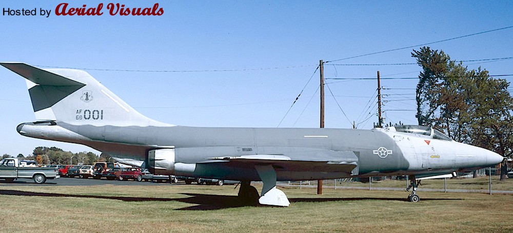
This preserved machine wore a rather unusual (for a Voodoo) ‘Hill’ low-viz scheme with toned-down markings, quite similar to the late USAF F-4 Phantom IIs of the early Eighties. The big aircraft looked quite good in this simple livery, and I kept the idea of a Hill scheme Voodoo in the back of my mind for some years until I recently had the opportunity to buy a cheap Matchbox Voodoo w/o box and decals. With its optional (and unique) RF-101B parts I decided to take the Hill Voodoo idea to the hardware stage and create another submission to the “Reconnaissance and Surveillance” group build at whatifmodellers.com around July 2021: an ANG recce conversion of a former two-seat interceptor, using the RF-101B as benchmark but with a different suite of sensors.
However, the Matchbox Voodoo kit is rather mediocre, and in a rather ambitious mood I decided to “upgrade” the project with a Revell F-101B as the model’s basis. This kit is from 1991 and a MUCH better and finely detailed model than the rather simple Matchbox kit from the early Eighties. In fact, the Revell F-101B is actually a scaled-down version of Monogram’s 1:48 F-101B model kit from 1985, with many delicate details. But while this downscaling practice has produced some very nice 1:72 models like the F-105D or the F-4D, the scaling effect caused IMHO in this case a couple of problems. Revell's assembly instructions for the 1:72 kit are not good, either. While the step-by-step documentation is basically good, some sketches are so cluttered that you cannot tell where parts in the cockpit or on the landing gear are actually intended to be placed and how. This is made worse by the fact that there are no suitable markings on the parts – you are left to guessing.
Worse, there is a massive construction error: the way the wings section is to be assembled and mounted to the hull is impossible! The upper wing halves have locator pins for the fuselage, but they are supposed to be glued to the lower wing half (which also encompasses the aircraft's belly) and the mounted to the hull. The locator pins make this impossible, unless you bend the lower wing section to a point where it might warp or break, or you just cut the pins off - and live with some instability. Technically the upper wing halves have to be mounted to the fuselage before you glue the lower wing section to them, but I am not certain if this would work well because you also have to assemble the air intakes at the same time “from behind”, which is only feasible when the wings have already been completed but still left away from the fuselage. It’s a nonsense construction! I cannot remember when I came across a kit the last time with such an inherent design flaw?
Except for the transplanted RF-101B nose section, which did not fit well because the Matchbox Voodoo apparently has a more slender nose, the Revell kit was built mostly OOB. However, this is already a challenge in itself because of the kit’s inherent flaws (see above), its complex construction and an unorthodox assembly sequence, due to many separate internal modules including the cockpit tub, a separate (fully detailed) front landing gear well, a rotating weapon bay, air intakes with complete ducts, and the wing section. A fiddly affair.
Only a few further changes beyond the characteristic camera fairing under the radome were made. The rotating weapon bay was faired-over with the original weapon pallet, just fixing it into place and using putty to blend it into the belly. The small underwing pylons (an upgrade that actually happened to some late Voodoos) were taken from a vintage Revell F-16. The SLAR antenna fairings along the cockpit flanks were created with 0.5mm styrene sheet and some PSR. They are a little too obvious/protruding, but for a retrofitted solution I find the result acceptable. The drop tanks came from the Revell kit, the underwing ordnance consists of an ALQ-119 ECM pod from a Hasegawa aftermarket set and a SUU-42 dispenser, scratched from a Starfighter ventral drop tank, bomb fins and the back of a Soviet unguided missile launcher.
Painting and markings:
Very simple and basic. While I originally wanted to adopt the simple two-tone ‘Hill’ scheme from the gate guard for my fictional Voodoo, I eventually settled for the very similar but slightly more sophisticated ‘Egypt One’ scheme that was introduced with the first F-16s – it just works better on the F-101’s surfaces. This scheme uses three grey tones: FS 36118 (Gunship Gray, ModelMaster 1723) for the upper wing surfaces, the “saddle” on the fuselage and the canopy area with an anti-glare panel, FS 36270 (Medium Grey, Humbrol 126) on the fin and the fuselage area in front of the wing roots, and FS 36375 (Light Ghost Grey, Humbrol 127) for all lower surfaces, all blended into each other with straight but slightly blurred edges (created with a soft, flat brush). The radome and the conformal antennae on the flanks became Revell 47 for a consistent grey-in-grey look, but with a slightly different shade. The model received an overall black ink washing and some post panel shading, so that the large grey areas would not look too uniform.
As an updated USAF aircraft I changed the color of the landing gear wells’ interior from green zinc chromate primer to more modern, uniform white, even though the red inside of the covers was retained. The interior of the flaps (a nice OOB option of Revell’s kit) and the air brakes became bright red, too.
The cockpit retained its standard medium grey (Humbrol 140, Dark Gull Grey) interior and I used the instrument decals from the kit – even though these did not fit well onto the 3D dashboards and side consoles. WTF? Decal softener came to the rescue. The exhaust area was painted with Revell 91 (Iron) and Humbrol’s Steel Metallizer (27003), later treated with graphite for a dirty, metallic shine.
Markings/decals primarily come from a 1:72 Hi-Decal F-4D sheet that contains (among others) several Texas ANG Phantoms from the mid-Eighties. Some stencils were taken over from the original Voodoo sheet, the yellow formation lights had to be procured from a Hasegawa F-4E/J sheet (the Matchbox sheet was lost and the Revell sheet lacks them completely!). The characteristic deep yellow canopy sealant stripes came from a CF-101 sheet from Winter Valley Decals (today part of Canuck Models as CAD 72008). I was lucky to have them left over from another what-if build MANY moons ago, my fictional CF-151 kitbashing.
Everything went on smoothly, but the walkway markings above the air intakes became a problem. I initially used those from the Revell sheet, which are only the outlines so that the camouflage would still be visible. But the decal film, which is an open square, turned out to be so thin that it wrinkled on the curved surface whatever I tried, and what looked like a crisp black outline on the white decal paper turned out to be a translucent dark blue with blurry edges on the kit. I scrapped them while still wet… Enter plan B: Next came the walkway markings from the aforementioned Winter Valley sheet, which were MUCH better, sharper and opaque, but they included the grey walking areas. While the tone looked O.K. on the sheet it turned out to be much too light for the all-grey Voodoo, standing out and totally ruining the low-viz look. With a bleeding heart I eventually ripped them off of the model with the help of adhesive tape, what left light grey residues. Instead of messing even more with the model I finally decided to embrace this accident and manually added a new black frame to the walkway areas with generic 2mm decal stripe material from TL Modellbau The area now looks rather worn, as if the camouflage had peeled off and light grey primer shows through. An unintentional result, but it looks quite “natural”.
The “Rhino Express” nose art was created with Corel Draw and produced with a simple inkjet printer on clear decal sheet. It was inspired by the “toenail” decoration on the main landing gear covers, a subtle detail I saw IIRC on a late CF-101B and painted onto the model by hand. With its all-grey livery, the rhino theme appeared so appropriate, and the tag on the nose appeared like a natural addition. It’s all not obvious but adds a personal touch to the aircraft.
Finally, after some more exhaust stains had been added to various air outlets around the hull, the model was sealed with matt acrylic varnish, position lights were added with clear paint and the camera windows, which had been created with black decal material, received glossy covers. The IRST sensor was painted with translucent black over a gold base.
Well, while the all-grey USAF livery in itself is quite dull and boring, but I must say that it suits the huge and slender Voodoo well. It emphasizes the aircraft's sleek lines and the Texas ANG fin flash as a colorful counterpoint, as well as the many red interior sections that only show from certain angles, nicely break the adapted low-viz Egypt One livery up. The whole thing looks surprisingly convincing, and the subtle rhino markings add a certain tongue-in-cheek touch.
Nikon’s in-camera Picture Control system offers a range of preset options and you can create custom controls for specific subjects and scenes. Easily define parameters such as sharpness, saturation, and hue whether you’re shooting stills or video.
Photo © Vivien Liu
I was interested to see this, the only member of Class 89 at Barrow Hill, it is being worked on, but looks a long way from being ready to move under its own power.
--------------------------------------------
The Class 89 was a prototype design for an electric locomotive. Only one was built in 1986, by British Rail Engineering Limited's Crewe Works. It was used on test-trains on both the West Coast and East Coast Main Lines. It was fitted with advanced power control systems and developed over 6,000 bhp (4,500 kW). It was given the nickname Aardvark although railfans used to call it The Badger owing to its slanted front ends
The Class 89 locomotive was designed by Brush Traction, Loughborough to meet a specification issued by British Rail, which subsequently changed the requirements, but not before Brush had already committed to build the prototype locomotive.
The locomotive had six DC traction motors. The main armature current for all the motors is fed from a common thyristor drive, whilst each motor has an independent field current controller. The field current controllers comprised a two quadrant chopper inside a thyristor bridge. The bipolar transistor based choppers provides a fast fine control of motor torque for electric braking and slip control, whilst the thyristor bridge is used to invert the field current polarity.
The locomotive was built at British Rail Engineering Limited's Crewe Works, between 1985–87,[2] emerging and being initially delivered to Derby Litchurch Lane Works on 2 October 1986.[4][7] The Class 89 was then transferred by road to Brush Traction at Loughborough, for static testing and commissioning.[4] It was initially delivered in the old-style InterCity Executive livery, with no British Rail double arrows, but these were added later when British Rail bought the locomotive from Brush.[citation needed]
The locomotive's first powered working was on 9 February 1987, and its first lone run was on 20 February 1987.[7] In April 1987, 89001 visited the Old Dalby Test Track for evaluation.[8] The locomotive was initially allocated to Crewe Electric depot, for trials along the West Coast Main Line.[2] Following the successful testing, 89001 was transferred to Hornsey, and later to Bounds Green, for passenger services on the East Coast Main Line.[2] In May 1988, the locomotive returned to Old Dalby for braking trials.[8] During the early summer of 1988, the International Traffic and Transport Exhibition (IVA88) was held in Hamburg, Germany. British Rail was asked to participate and sent a representative train of rolling stock to the exhibition. On 22 May 1988, 89001 along with a Class 90, Class 91[5] and a two car Class 150/2 unit left for Hamburg, returning on 17 June 1988.
After being used as a test bed, the locomotive was used on passenger trains from London King's Cross to Leeds. As the development of the ECML Electrification continued the engine was painted into the new style InterCity Swallow livery and named Avocet, in recognition of the Royal Society for the Protection of Birds (RSPB),[5] by Prime Minister Margaret Thatcher on 16 January 1989 at King's Cross station.[9] After the ceremony, the locomotive hauled a special train conveying the RSPB president Magnus Magnusson, along with other VIPs, to Sandy.[10] Passenger use continued on the ECML until 5 March 1989, a week before the Class 91s entered service on the diagrams.
All hope and opportunity ended, however, when 89001 suffered a serious failure and was withdrawn from traffic in July 1992.[2] When 89001 failed, it was still owned by British Rail, and Brush had no contractual obligation with regard to it. Additionally, having no orders from BR for their design investment, there was little incentive for Brush to construct spare parts for it. BR had written off the locomotive as part of the ECML development and thus it was seen as a surplus and nil value asset. As such, the locomotive was sidelined.
It was saved for preservation at the Midland Railway Centre by a group of Brush Traction employees.[11] During this time the locomotive appeared at every major British Rail depot open day, in a slowly deteriorating Intercity Swallow livery.
It was hoped that the Class 89 design would be used for electric locomotives for the Channel Tunnel, and some investigation was undertaken. It was also hoped the Class 89 would be a viable Class 86 replacement, however an upgraded version of the Class 87 was ordered as the Class 90 instead.
Ultimately only technology and ideas from 89001's internal design were used in the Class 9 Eurotunnel locomotives and some similarity in electronics lives on today in the Class 92 locomotive design. Brush did eventually win the contracts to build Channel Tunnel locomotives, and the similarities between these and 89001 enabled suitable spares to be constructed.
In 1996, the InterCity East Coast franchise was won by the Great North Eastern Railway (GNER). Suffering from a motive power shortage, it purchased 89001 and repaired it for use on London to Leeds and Bradford services, investing £100 000 in an overhaul.[12] It was also re-painted in the GNER blue and orange livery.[13] The locomotive returned to service in March 1997.[14] However, in 2001, the locomotive again suffered a major failure and was withdrawn from traffic. Its future was again in doubt, and it was laid up for a period at Doncaster Works.
In December 2004, the locomotive was moved into the care of the AC Locomotive Group at Barrow Hill Engine Shed for secure storage. With the overhaul of the Class 91 fleet complete, plus the availability of Class 373 trains for lease, 89001 was seen as a one-off asset with little economic value.
In October 2006, GNER put 89001 up for sale with a six-week deadline for bids. The AC Locomotive Group launched an appeal and fundraising effort to save the locomotive which was ultimately successful, purchasing the locomotive in December 2006.[15] The locomotive is mostly complete although a number of major components require expensive overhaul before the loco could run on the main line again. A thorough survey has been undertaken to establish exactly what is required, and costs drawn up. Cosmetic work in 2007 saw the loco return to its original InterCity Executive colour scheme. Electrical restoration work has focussed on repairing and/or refurbishing the items that led to the locomotive being withdrawn from service, namely the traction motors and their associated field converter electronics. The locomotive was lifted by Harry Needle Railroad Company at Barrow Hill Engine Shed in December 2010, and three traction motors were removed including the one known to be faulty. These are currently (February 2011) being examined at Bowers to allow repair cost estimates to be made. Two of the field converters have been removed, one is faulty and again repair estimates are being sought. Initially it is intended, as funds become available, to allow one power group (i.e. one bogie) to become fully operational.
After many months of waiting, 2 September finally saw testing of the first field converter overhauled at Fletcher Moorland Ltd, Stoke. There will be several iterations of testing so that there is a full understanding of any remaining defects and ensure that all aged or failed components are changed. The overhauled converter was completely dismantled with each power component being checked and replaced where required. A number of components were found to be performing outside of their specification and have been changed. The three control PCBs, these run the height of the converter, totalling the best part of £1m. The largest of the three is 2/3 of that. All electrolytic capacitors have been changed, both on the control PCBs and in the power circuit. These deteriorate with age.
WSP test train at Winsford, June 1988 - new design of WSP control system was fitted to a Mk III locomotive hauled coach number 17174, Other vehicles in the train are ADW150375, RDB975428 and ADB975397.
Read about how and why trains were tested in the 80s and 90s in my RAIL VEHICLE TESTING book - ISBN-9781999935603.
© Dave Bower - Rail Vehicle Testing
AT8RC telescope on a Losmandy G11 mount using a Gemini 2 control system. The camera used in this setup is a modified Canon 450d. The guidescope is an Orion ST80 using an Orion Star Shoot Autoguider camera for tracking.
The AT8RC is an 8" Ritchey-Chrétien design astrograph.
Object Details: The Horsehead Nebula (Barnard 33) is a dark cloud of dust and gas (i.e. a 'dark' nebula) located in the constellation of Orion, and is a part of the much larger Orion Molecular Cloud Complex (a massive star forming region). It lies approximately 1500 light-years from Earth and spans about 7 light-years in diameter. The Flame Nebula (seen to the lower left of the Horsehead in the wide-field image) is an emission nebula which spans about 12 light-years in diameter and also lies approximately 1500 light-years away. In it's case at it's core lies a young star cluster consisting of several hundred stars, most of which have been found to be surrounded by circumstellar disks (i.e. potential planetary systems in various stages of formation).
Image Details: The attached is a composite of two images, taken simultaneously using twin (unmodded) Canon 700D (t5i) DSLRs with (left) an ED80T CF (i.e. a carbon-fiber 80mm, f/6 apochromatic refractor) with a Televue 0.8X field flatener / focal reducer; and (right) an 8-inch, f/7 Criterion newtonian reflector with a coma corrector. The 80mm was piggybacked on the 8-inch (along with a second 80mm Celestron 'short-tube' as a guidescope), which was tracked on a Losmandy G-11 mount running a Gemini 2 control system and guided using an ASI290MC & PHD2. These are just quickly (and terribly ;) ) processed, relatively short exposure test shots taken to determine the area's applicability to simultaneous imaging through some of the various focal lengths we have available. A similar framing test of the Orion & Running Man nebulae taken the same evening can be found at the link attached here: www.flickr.com/photos/homcavobservatory/46195697944/
while a similar composite of the Pleiades taken while testing a new remote connection to our obs. can be found here: www.flickr.com/photos/homcavobservatory/40317389883/
+++ DISCLAIMER +++
Nothing you see here is real, even though the conversion or the presented background story might be based on authentic facts. BEWARE!
Some background:
The РТАК-30 attack vintoplan (also known as vintokryl) owed its existence to the Mil Mi-30 plane/helicopter project that originated in 1972. The Mil Mi-30 was conceived as a transport aircraft that could hold up to 19 passengers or two tons of cargo, and its purpose was to replace the Mi-8 and Mi-17 Helicopters in both civil and military roles. With vertical takeoff through a pair of tiltrotor engine pods on the wing tips (similar in layout to the later V-22 Osprey) and the ability to fly like a normal plane, the Mil Mi-30 had a clear advantage over the older models.
Since the vintoplan concept was a completely new field of research and engineering, a dedicated design bureau was installed in the mid-Seventies at the Rostov-na-Donu helicopter factory, where most helicopters from the Mil design bureau were produced, under the title Ростов Тилт Ротор Авиационная Компания (Rostov Tilt Rotor Aircraft Company), or РТАК (RTRA), for short.
The vintoplan project lingered for some time, with basic research being conducted concerning aerodynamics, rotor design and flight control systems. Many findings later found their way into conventional planes and helicopters. At the beginning of the 1980s, the project had progressed far enough that the vintoplan received official backing so that РТАК scientists and Mil helicopter engineers assembled and tested several layouts and components for this complicated aircraft type.
At that time the Mil Mi-30 vintoplan was expected to use a single TV3-117 Turbo Shaft Engine with a four-bladed propeller rotors on each of its two pairs of stub wings of almost equal span. The engine was still installed in the fuselage and the proprotors driven by long shafts.
However, while being a very clean design, this original layout revealed several problems concerning aeroelasticity, dynamics of construction, characteristics for the converter apparatuses, aerodynamics and flight dynamics. In the course of further development stages and attempts to rectify the technical issues, the vintoplan layout went through several revisions. The layout shifted consequently from having 4 smaller engines in rotating pods on two pairs of stub wings through three engines with rotating nacelles on the front wings and a fixed, horizontal rotor over the tail and finally back to only 2 engines (much like the initial concept), but this time mounted in rotating nacelles on the wing tips and a canard stabilizer layout.
In August 1981 the Commission of the Presidium of the USSR Council of Ministers on weapons eventually issued a decree on the development of a flyworthy Mil Mi-30 vintoplan prototype. Shortly afterwards the military approved of the vintoplan, too, but desired bigger, more powerful engines in order to improve performance and weight capacity. In the course of the ensuing project refinement, the weight capacity was raised to 3-5 tons and the passenger limit to 32. In parallel, the modified type was also foreseen for civil operations as a short range feederliner, potentially replacing Yak-40 and An-24 airliners in Aeroflot service.
In 1982, РТАК took the interest from the military and proposed a dedicated attack vintoplan, based on former research and existing components of the original transport variant. This project was accepted by MAP and received the separate designation РТАК-30. However, despite having some close technical relations to the Mi-30 transport (primarily the engine nacelles, their rotation mechanism and the flight control systems), the РТАК-30 was a completely different aircraft. The timing was good, though, and the proposal was met with much interest, since the innovative vintoplan concept was to compete against traditional helicopters: the design work on the dedicated Mi-28 and Ka-50 attack helicopters had just started at that time, too, so that РТАК received green lights for the construction of five prototypes: four flyworthy machines plus one more for static ground tests.
The РТАК-30 was based on one of the early Mi-30 layouts and it combined two pairs of mid-set wings with different wing spans with a tall tail fin that ensured directional stability. Each wing carried a rotating engine nacelle with a so-called proprotor on its tip, each with three high aspect ratio blades. The proprotors were handed (i.e. revolved in opposite directions) in order to minimize torque effects and improve handling, esp. in the hover. The front and back pair of engines were cross-linked among each other on a common driveshaft, eliminating engine-out asymmetric thrust problems during V/STOL operations. In the event of the failure of one engine, it would automatically disconnect through torque spring clutches and both propellers on a pair of wings would be driven by the remaining engine.
Four engines were chosen because, despite the weight and complexity penalty, this extra power was expected to be required in order to achieve a performance that was markedly superior to a conventional helicopter like the Mi-24, the primary Soviet attack helicopter of that era the РТАК-30 was supposed to replace. It was also expected that the rotating nacelles could also be used to improve agility in level flight through a mild form of vectored thrust.
The РТАК-30’s streamlined fuselage provided ample space for avionics, fuel, a fully retractable tricycle landing gear and a two man crew in an armored side-by-side cockpit with ejection seats. The windshield was able to withstand 12.7–14.5 mm caliber bullets, the titanium cockpit tub could take hits from 20 mm cannon. An autonomous power unit (APU) was housed in the fuselage, too, making operations of the aircraft independent from ground support.
While the РТАК-30 was not intended for use as a transport, the fuselage was spacious enough to have a small compartment between the front wings spars, capable of carrying up to three people. The purpose of this was the rescue of downed helicopter crews, as a cargo hold esp. for transfer flights and as additional space for future mission equipment or extra fuel.
In vertical flight, the РТАК-30’s tiltrotor system used controls very similar to a twin or tandem-rotor helicopter. Yaw was controlled by tilting its rotors in opposite directions. Roll was provided through differential power or thrust, supported by ailerons on the rear wings. Pitch was provided through rotor cyclic or nacelle tilt and further aerodynamic surfaces on both pairs of wings. Vertical motion was controlled with conventional rotor blade pitch and a control similar to a fixed-wing engine control called a thrust control lever (TCL). The rotor heads had elastomeric bearings and the proprotor blades were made from composite materials, which could sustain 30 mm shells.
The РТАК-30 featured a helmet-mounted display for the pilot, a very modern development at its time. The pilot designated targets for the navigator/weapons officer, who proceeded to fire the weapons required to fulfill that particular task. The integrated surveillance and fire control system had two optical channels providing wide and narrow fields of view, a narrow-field-of-view optical television channel, and a laser rangefinder. The system could move within 110 degrees in azimuth and from +13 to −40 degrees in elevation and was placed in a spherical dome on top of the fuselage, just behind the cockpit.
The aircraft carried one automatic 2A42 30 mm internal gun, mounted semi-rigidly fixed near the center of the fuselage, movable only slightly in elevation and azimuth. The arrangement was also regarded as being more practical than a classic free-turning turret mount for the aircraft’s considerably higher flight speed than a normal helicopter. As a side effect, the semi-rigid mounting improved the cannon's accuracy, giving the 30 mm a longer practical range and better hit ratio at medium ranges. Ammunition supply was 460 rounds, with separate compartments for high-fragmentation, explosive incendiary, or armor-piercing rounds. The type of ammunition could be selected by the pilot during flight.
The gunner can select one of two rates of full automatic fire, low at 200 to 300 rds/min and high at 550 to 800 rds/min. The effective range when engaging ground targets such as light armored vehicles is 1,500 m, while soft-skinned targets can be engaged out to 4,000 m. Air targets can be engaged flying at low altitudes of up to 2,000 m and up to a slant range of 2,500 m.
A substantial range of weapons could be carried on four hardpoints under the front wings, plus three more under the fuselage, for a total ordnance of up to 2,500 kg (with reduced internal fuel). The РТАК-30‘s main armament comprised up to 24 laser-guided Vikhr missiles with a maximum range of some 8 km. These tube-launched missiles could be used against ground and aerial targets. A search and tracking radar was housed in a thimble radome on the РТАК-30’s nose and their laser guidance system (mounted in a separate turret under the radome) was reported to be virtually jam-proof. The system furthermore featured automatic guidance to the target, enabling evasive action immediately after missile launch. Alternatively, the system was also compatible with Ataka laser-guided anti-tank missiles.
Other weapon options included laser- or TV-guided Kh-25 missiles as well as iron bombs and napalm tanks of up to 500 kg (1.100 lb) caliber and several rocket pods, including the S-13 and S-8 rockets. The "dumb" rocket pods could be upgraded to laser guidance with the proposed Ugroza system. Against helicopters and aircraft the РТАК-30 could carry up to four R-60 and/or R-73 IR-guided AAMs. Drop tanks and gun pods could be carried, too.
When the РТАК-30's proprotors were perpendicular to the motion in the high-speed portions of the flight regime, the aircraft demonstrated a relatively high maximum speed: over 300 knots/560 km/h top speed were achieved during state acceptance trials in 1987, as well as sustained cruise speeds of 250 knots/460 km/h, which was almost twice as fast as a conventional helicopter. Furthermore, the РТАК-30’s tiltrotors and stub wings provided the aircraft with a substantially greater cruise altitude capability than conventional helicopters: during the prototypes’ tests the machines easily reached 6,000 m / 20,000 ft or more, whereas helicopters typically do not exceed 3,000 m / 10,000 ft altitude.
Flight tests in general and flight control system refinement in specific lasted until late 1988, and while the vintoplan concept proved to be sound, the technical and practical problems persisted. The aircraft was complex and heavy, and pilots found the machine to be hazardous to land, due to its low ground clearance. Due to structural limits the machine could also never be brought to its expected agility limits
During that time the Soviet Union’s internal tensions rose and more and more hampered the РТАК-30’s development. During this time, two of the prototypes were lost (the 1st and 4th machine) in accidents, and in 1989 only two machines were left in flightworthy condition (the 5th airframe had been set aside for structural ground tests). Nevertheless, the РТАК-30 made its public debut at the Paris Air Show in June 1989 (the 3rd prototype, coded “33 Yellow”), together with the Mi-28A, but was only shown in static display and did not take part in any flight show. After that, the aircraft received the NATO ASCC code "Hemlock" and caused serious concern in Western military headquarters, since the РТАК-30 had the potential to dominate the European battlefield.
And this was just about to happen: Despite the РТАК-30’s development problems, the innovative attack vintoplan was included in the Soviet Union’s 5-year plan for 1989-1995, and the vehicle was eventually expected to enter service in 1996. However, due to the collapse of the Soviet Union and the dwindling economics, neither the РТАК-30 nor its civil Mil Mi-30 sister did soar out in the new age of technology. In 1990 the whole program was stopped and both surviving РТАК-30 prototypes were mothballed – one (the 3rd prototype) was disassembled and its components brought to the Rostov-na-Donu Mil plant, while the other, prototype No. 1, is rumored to be stored at the Central Russian Air Force Museum in Monino, to be restored to a public exhibition piece some day.
General characteristics:
Crew: Two (pilot, copilot/WSO) plus space for up to three passengers or cargo
Length: 45 ft 7 1/2 in (13,93 m)
Rotor diameter: 20 ft 9 in (6,33 m)
Wingspan incl. engine nacelles: 42 ft 8 1/4 in (13,03 m)
Total width with rotors: 58 ft 8 1/2 in (17,93 m)
Height: 17 ft (5,18 m) at top of tailfin
Disc area: 4x 297 ft² (27,65 m²)
Wing area: 342.2 ft² (36,72 m²)
Empty weight: 8,500 kg (18,740 lb)
Max. takeoff weight: 12,000 kg (26,500 lb)
Powerplant:
4× Klimov VK-2500PS-03 turboshaft turbines, 2,400 hp (1.765 kW) each
Performance:
Maximum speed: 275 knots (509 km/h, 316 mph) at sea level
305 kn (565 km/h; 351 mph) at 15,000 ft (4,600 m)
Cruise speed: 241 kn (277 mph, 446 km/h) at sea level
Stall speed: 110 kn (126 mph, 204 km/h) in airplane mode
Range: 879 nmi (1,011 mi, 1,627 km)
Combat radius: 390 nmi (426 mi, 722 km)
Ferry range: 1,940 nmi (2,230 mi, 3,590 km) with auxiliary external fuel tanks
Service ceiling: 25,000 ft (7,620 m)
Rate of climb: 2,320–4,000 ft/min (11.8 m/s)
Glide ratio: 4.5:1
Disc loading: 20.9 lb/ft² at 47,500 lb GW (102.23 kg/m²)
Power/mass: 0.259 hp/lb (427 W/kg)
Armament:
1× 30 mm (1.18 in) 2A42 multi-purpose autocannon with 450 rounds
7 external hardpoints for a maximum ordnance of 2.500 kg (5.500 lb)
The kit and its assembly:
This exotic, fictional aircraft-thing is a contribution to the “The Flying Machines of Unconventional Means” Group Build at whatifmodelers.com in early 2019. While the propulsion system itself is not that unconventional, I deemed the quadrocopter concept (which had already been on my agenda for a while) to be suitable for a worthy submission.
The Mil Mi-30 tiltrotor aircraft, mentioned in the background above, was a real project – but my alternative combat vintoplan design is purely speculative.
I had already stashed away some donor parts, primarily two sets of tiltrotor backpacks for 1:144 Gundam mecha from Bandai, which had been released recently. While these looked a little toy-like, these parts had the charm of coming with handed propellers and stub wings that would allow the engine nacelles to swivel.
The search for a suitable fuselage turned out to be a more complex safari than expected. My initial choice was the spoofy Italeri Mi-28 kit (I initially wanted a staggered tandem cockpit), but it turned out to be much too big for what I wanted to achieve. Then I tested a “real” Mi-28 (Dragon) and a Ka-50 (Italeri), but both failed for different reasons – the Mi-28 was too slender, while the Ka-50 had the right size – but converting it for my build would have been VERY complicated, because the engine nacelles would have to go and the fuselage shape between the cockpit and the fuselage section around the original engines and stub wings would be hard to adapt. I eventually bought an Italeri Ka-52 two-seater as fuselage donor.
In order to mount the four engines to the fuselage I’d need two pairs of wings of appropriate span – and I found a pair of 1:100 A-10 wings as well as the wings from an 1:72 PZL Iskra (not perfect, but the most suitable donor parts I could find in the junkyard). On the tips of these wings, the swiveling joints for the engine nacelles from the Bandai set were glued. While mounting the rear wings was not too difficult (just the Ka-52’s OOB stabilizers had to go), the front pair of wings was more complex. The reason: the Ka-52’s engines had to go and their attachment points, which are actually shallow recesses on the kit, had to be faired over first. Instead of filling everything with putty I decided to cover the areas with 0.5mm styrene sheet first, and then do cosmetic PSR work. This worked quite well and also included a cover for the Ka-52’s original rotor mast mount. Onto these new flanks the pair of front wings was attached, in a mid position – a conceptual mistake…
The cockpit was taken OOB and the aircraft’s nose received an additional thimble radome, reminiscent of the Mi-28’s arrangement. The radome itself was created from a German 500 kg WWII bomb.
At this stage, the mid-wing mistake reared its ugly head – it had two painful consequences which I had not fully thought through. Problem #1: the engine nacelles turned out to be too long. When rotated into a vertical position, they’d potentially hit the ground! Furthermore, the ground clearance was very low – and I decided to skip the Ka-52’s OOB landing gear in favor of a heavier and esp. longer alternative, a full landing gear set from an Italeri MiG-37 “Ferret E” stealth fighter, which itself resembles a MiG-23/27 landing gear. Due to the expected higher speeds of the vintoplan I gave the landing gear full covers (partly scratched, plus some donor parts from an Academy MiG-27). It took some trials to get the new landing gear into the right position and a suitable stance – but it worked. With this benchmark I was also able to modify the engine nacelles, shortening their rear ends. They were still very (too!) close to the ground, but at least the model would not sit on them!
However, the more complete the model became, the more design flaws turned up. Another mistake is that the front and rear rotors slightly overlap when in vertical position – something that would be unthinkable in real life…
With all major components in place, however, detail work could proceed. This included the completion of the cockpit and the sensor turrets, the Ka-52 cannon and finally the ordnance. Due to the large rotors, any armament had to be concentrated around the fuselage, outside of the propeller discs. For this reason (and in order to prevent the rear engines to ingest exhaust gases from the front engines in level flight), I gave the front wings a slightly larger span, so that four underwing pylons could be fitted, plus a pair of underfuselage hardpoints.
The ordnance was puzzled together from the Italeri Ka-52 and from an ESCI Ka-34 (the fake Ka-50) kit.
Painting and markings:
With such an exotic aircraft, I rather wanted a conservative livery and opted for a typical Soviet tactical four-tone scheme from the Eighties – the idea was to build a prototype aircraft from the state acceptance trials period, not a flashy demonstrator. The scheme and the (guesstimated) colors were transferred from a Soviet air force MiG-21bis of that era, and it consists of a reddish light brown (Humbrol 119, Light Earth), a light, yellowish green (Humbrol 159, Khaki Drab), a bluish dark green (Humbrol 195, Dark Satin Green, a.k.a. RAL 6020 Chromdioxidgrün) and a dark brown (Humbrol 170, Brown Bess). For the undersides’ typical bluish grey I chose Humbrol 145 (FS 35237, Gray Blue), which is slightly lighter and less greenish than the typical Soviet tones. A light black ink wash was applied and some light post-shading was done in order to create panels that are structurally not there, augmented by some pencil lines.
The cockpit became light blue (Humbrol 89), with medium gray dashboard and consoles. The ejection seats received bright yellow seatbelts and bright blue pads – a detail seen on a Mi-28 cockpit picture.
Some dielectric fairings like the fin tip were painted in bright medium green (Humbrol 101), while some other antenna fairings were painted in pale yellow (Humbrol 71).
The landing gear struts and the interior of the wells became Aluminum Metalic (Humbrol 56), the wheels dark green discs (Humbrol 30).
The decals were puzzled together from various sources, including some Begemot sheets. Most of the stencils came from the Ka-52 OOB sheet, and generic decal sheet material was used to mark the walkways or the rotor tips and leading edges.
Only some light weathering was done to the leading edges of the wings, and then the kit was sealed with matt acrylic varnish.
A complex kitbashing project, and it revealed some pitfalls in the course of making. However, the result looks menacing and still convincing, esp. in flight – even though the picture editing, with four artificially rotating proprotors, was probably more tedious than building the model itself!
Some background:
The VF-1 was developed by Stonewell/Bellcom/Shinnakasu for the U.N. Spacy by using alien Overtechnology obtained from the SDF-1 Macross alien spaceship. Its production was preceded by an aerodynamic proving version of its airframe, the VF-X. Unlike all later VF vehicles, the VF-X was strictly a jet aircraft, built to demonstrate that a jet fighter with the features necessary to convert to Battroid mode was aerodynamically feasible. After the VF-X's testing was finished, an advanced concept atmospheric-only prototype, the VF-0 Phoenix, was flight-tested from 2005 to 2007 and briefly served as an active-duty fighter from 2007 to the VF-1's rollout in late 2008, while the bugs were being worked out of the full-up VF-1 prototype (VF-X-1).
The space-capable VF-1's combat debut was on February 7, 2009, during the Battle of South Ataria Island - the first battle of Space War I - and remained the mainstay fighter of the U.N. Spacy for the entire conflict. Introduced in 2008, the VF-1 would be out of frontline service just five years later, though.
The VF-1 proved to be an extremely capable craft, successfully combating a variety of Zentraedi mecha even in most sorties which saw UN Spacy forces significantly outnumbered. The versatility of the Valkyrie design enabled the variable fighter to act as both large-scale infantry and as air/space superiority fighter. The signature skills of U.N. Spacy ace pilot Maximilian Jenius exemplified the effectiveness of the variable systems as he near-constantly transformed the Valkyrie in battle to seize advantages of each mode as combat conditions changed from moment to moment.
The basic VF-1 was deployed in four sub-variants (designated A, D, J, and S) and its success was increased by continued development of various enhancements including the GBP-1S "Armored" Valkyrie, FAST Pack "Super" Valkyrie and the additional RÖ-X2 heavy cannon pack weapon system for the VF-1S for additional firepower. The FAST Pack system was designed to enhance the VF-1 Valkyrie variable fighter, and the initial V1.0 came in the form of conformal pallets that could be attached to the fighter’s leg flanks for additional fuel – primarily for Long Range Interdiction tasks in atmospheric environment. Later FAST Packs were designed for space operations.
After the end of Space War I, the VF-1 continued to be manufactured both in the Sol system and throughout the UNG space colonies. Although the VF-1 would be replaced in 2020 as the primary Variable Fighter of the U.N. Spacy by the more capable, but also much bigger, VF-4 Lightning III, a long service record and continued production after the war proved the lasting worth of the design.
The versatile aircraft underwent constant upgrade programs. For instance, about a third of all VF-1 Valkyries were upgraded with Infrared Search and Track (IRST) systems from 2016 onwards, placed in a streamlined fairing in front of the cockpit. This system allowed for long-range search and track modes, freeing the pilot from the need to give away his position with active radar emissions, and it could also be used for target illumination and guiding precision weapons.
Many Valkyries also received improved radar warning systems, with sensor arrays, depending on the systems, mounted on the wing-tips, on the fins and/or on the LERXs. Improved ECR measures were also added to some machines, typically in conformal fairings on the flanks of the legs/engine pods.
The U.N.S. Marine Corps, which evolved from the United States Marine Corps after the national service was transferred to the global U.N. Spacy command in 2008, was a late adopter of the VF-1, because the Valkyries’ as well as the Destroids’ potential for landing operations was underestimated. But especially the VF-1’s versatility and VTOL capabilities made it a perfect candidate as a replacement for the service’s AV-8B Harrier II and AH-1 Cobra fleet in the close air support (CAS) and interdiction role. The first VF-1s were taken into service in January 2010 by SVMF-49 “Vikings” at Miramar Air Base in California/USA, and other units followed soon, immediately joining the battle against the Zentraedi forces.
The UNSMC’s VF-1s were almost identical to the standard Valkyries, but they had from the start additional hardpoints for light loads like sensor pods added to their upper legs, on the lower corners of the air intake ducts. These were intended to carry FLIR, laser target designators (for respective guided smart weapons) or ECM pods, while freeing the swiveling underwing hardpoints to offensive ordnance.
Insisting on their independent heritage, the UNSMC’s Valkyries were never repainted in the U.N. Spacy’s standard tan and white livery. They either received a unique two tone low visibility gray paint scheme (the fighter units) or retained paint schemes that were typical for their former units, including some all-field green machines or VF-1s in a disruptive wraparound livery in grey, green and black.
Beyond A and J single-seaters (the UNSMC did not receive the premium S variant), a handful of VF-1D two-seaters were upgraded to the UNSMC’s specification and very effectively operated in the FAC (Forward Air Control) role, guiding both long-range artillery as well as attack aircraft against enemy positions.
The UNSMC’s VF-1s suffered heavy losses, though – for instance, SVMF-49 was completely wiped out during the so-called “Zentraedi Rain of Death” in April 2011, when the Zentraedi Imperial Grand Fleet, consisting of nearly five million warships, appeared in orbit around the Earth. Commanded by Dolza, Supreme Commander of the Zentraedi, they were ordered to incinerate the planet's surface, which they did. 70% of the Earth was utterly destroyed, according to the staff at Alaska Base. Dolza initially believed this to be total victory, until a massive energy pulse began to form on the Earth's surface. This was the Grand Cannon, a weapon of incredible destructive power that the Zentraedi were unaware of, and it disintegrated a good deal of the armada that was hanging over the Northern Hemisphere. While the Zentraedi were successful in rendering the weapon inoperable before it could fire a second time, the SDF-1 began a counterattack of its own alongside the renegade Imperial-Class Fleet and Seventh Mechanized Space Division, which destroyed the Imperial Grand Fleet. After this event, though, the UNSMC as well as other still independent services like the U.N. Navy were dissolved and the respective units integrated into the all-encompassing U.N. Spacy.
The VF-1 was without doubt the most recognizable variable fighter of Space War I and was seen as a vibrant symbol of the U.N. Spacy even into the first year of the New Era 0001 in 2013. At the end of 2015 the final rollout of the VF-1 was celebrated at a special ceremony, commemorating this most famous of variable fighters. The VF-1 Valkryie was built from 2006 to 2013 with a total production of 5,459 VF-1 variable fighters with several variants (VF-1A = 5,093, VF-1D = 85, VF-1J = 49, VF-1S = 30, VF-1G = 12, VE-1 = 122, VT-1 = 68)
However, the fighter remained active in many second line units and continued to show its worthiness years later, e. g. through Milia Jenius who would use her old VF-1 fighter in defense of the colonization fleet - 35 years after the type's service introduction!
General characteristics:
All-environment variable fighter and tactical combat Battroid,
used by U.N. Spacy, U.N. Navy, U.N. Space Air Force and U.N.S. Marine Corps
Accommodation:
Pilot only in Marty & Beck Mk-7 zero/zero ejection seat
Dimensions:
Fighter Mode:
Length 14.23 meters
Wingspan 14.78 meters (at 20° minimum sweep)
Height 3.84 meters
Battroid Mode:
Height 12.68 meters
Width 7.3 meters
Length 4.0 meters
Empty weight: 13.25 metric tons;
Standard T-O mass: 18.5 metric tons;
MTOW: 37.0 metric tons
Power Plant:
2x Shinnakasu Heavy Industry/P&W/Roice FF-2001 thermonuclear reaction turbine engines, output 650 MW each, rated at 11,500 kg in standard or 225.63 kN in overboost
4x Shinnakasu Heavy Industry NBS-1 high-thrust vernier thrusters (1 x counter reverse vernier thruster nozzle mounted on the side of each leg nacelle/air intake, 1 x wing thruster roll control system on each wingtip)
18x P&W LHP04 low-thrust vernier thrusters beneath multipurpose hook/handles
Performance:
Battroid Mode: maximum walking speed 160 km/h
Fighter Mode: at 10,000 m Mach 2.71; at 30,000+ m Mach 3.87
g limit: in space +7
Thrust-to-weight ratio: empty 3.47; standard T-O 2.49; maximum T-O 1.24
Design Features:
3-mode variable transformation; variable geometry wing; vertical take-off and landing; control-configurable vehicle; single-axis thrust vectoring; three "magic hand" manipulators for maintenance use; retractable canopy shield for Battroid mode and atmospheric reentry; option of GBP-1S system, atmospheric-escape booster, or FAST Pack system
Transformation:
Standard time from Fighter to Battroid (automated): under 5 sec.
Min. time from Fighter to Battroid (manual): 0.9 sec.
Armament:
2x Mauler RÖV-20 anti-aircraft laser cannon, firing 6,000 pulses per minute
1x Howard GU-11 55 mm three-barrel Gatling gun pod with 200 RPG, fired at 1,200 rds/min
4x underwing hard points for a wide variety of ordnance, including…
12x AMM-1 hybrid guided multipurpose missiles (3/point), or
12x MK-82 LDGB conventional bombs (3/point), or
6x RMS-1 large anti-ship reaction missiles (2/outboard point, 1/inboard point), or
4x UUM-7 micro-missile pods (1/point) each carrying 15 x Bifors HMM-01 micro-missiles,
or a combination of above load-outs
2x auxiliary hardpoints on the legs for light loads like a FLIR sensor, laser rangefinder/
target designator or ECM pod (typically not used for offensive ordnance)
The kit and its assembly:
This fictional VF-1 was born from spontaneous inspiration and the question if the USMC could have adopted the Valkyrie within the Macross time frame and applied its rather special grey/green/black paint scheme from the Nineties that was carried by AH-1s, CH-46s and also some OV-10s.
The model is a simple, vintage ARII VF-1 in Fighter mode, in this case a VF-1D two-seater that received the cockpit section and the head unit from a VF-1J Gerwalk model to create a single seater. While the parts are interchangeable, the Gerwalk and the Fighter kit have different molds for the cockpit sections and the canopies, too. This is mostly evident through the lack of a front landing gear well under the Gerwalk's cockpit - I had to "carve" a suitable opening into the bottom of the nose, but that was not a problem.
The kit was otherwiese built OOB, with the landing gear down and (finally, after the scenic flight pictures) with an open canopy for final display among the rest of my VF-1 fleet. However, I added some non-canonical small details like small hardpoints on the upper legs and the FLIR and targeting pods on them, scratched from styrene bits.
The ordnance was changed from twelve AMM-1 missiles under the wings to something better suited for attack missions. Finding suitable material became quite a challenge, though. I eventually settled on a pair of large laser-guided smart bombs and two pairs of small air-to-ground missile clusters. The LGBs are streamlined 1:72 2.000 lb general purpose bombs, IIRC from a Hobby Boss F-5E kit, and the launch tubes were scratched from a pair of Bazooka starters from an Academy 1:72 P-51 kit. The ventral standard GU-11 pod was retained and modified to hold a scratched wire display for in-flight pictures at its rear end.
Some blade antennae were added around the hull as a standard measure to improve the simple kit’s look. The cockpit was taken OOB, I just added a pilot figure for the scenic shots and the thick canopy was later mounted on a small lift arm in open position.
Painting and markings:
Adapting the characteristic USMC three-tone paint scheme for the VF-1 was not easy; I used the symmetric pattern from the AH-1s as starting point for the fuselage and gradually evolved it onto the wings into an asymmetric free-form pattern, making sure that the areas where low-viz roundels and some vital stencils would sit on grey for good contrast and readability. The tones became authentic: USMC Field Green (FS 34095, Humbrol 105), USN Medium Grey (FS 35237, Humbrol 145) and black (using Revell 06 Tar Black, which is a very dark grey and not pure black). For some contrast the wings' leading edges were painted with a sand brown/yellow (Humbrol 94).
The landing gear became standard white (Revell 301), the cockpit interior medium grey (Revell 47) with a black ejection seat with brown cushions, and the air intakes as well as the interior of the VG wings dark grey (Revell 77). To set the camouflaged nose radome apart I gave it a slightly different shade of green. The GU-11 pod became bare metal (Revell 91). The LGBs were painted olive drab overall while the AGMs became light grey.
Roundels as well as the UNSMC and unit tags were printed at home in black on clear decal sheet. The unit markings came from an Academy OV-10. The modex came from an 1:72 Revell F8F sheet. Stencils becvame eitrher black or white to keep the low-viz look, just a few tiny color highlights bereak the camouflage up. Some of the characteristic vernier thrusters around the hull are also self-made decals.
Finally, after some typical details and position lights were added with clear paint over a silver base, the small VF-1 was sealed with a coat of matt acrylic varnish.
A spontaneous interim project - and the UMSC's three-tone paint scheme suits the VF-1 well, which might have been a very suitable aircraft for this service and its mission profiles. I am still a bit uncertain about the camouflage's effectiveness, though - yes, it's disruptive, but the color contrasts are so high that a hiding effect seems very poor, even though I find that the scheme works well over urban terrain? It's fictional, though, and even though there are canonical U.N.S. Marines VF-1s to be found in literature, none I came across so far carried this type of livery.
You have to appreciate the brains of a garbage truck control system, because there is so much going on electrically when things are up and running constantly. This is especially the case when it comes to side loaders, given the wide array of functions and sensors that are interconnected so everything works as it should. Now not a very common sight on the modern garbage truck, in this picture we look inside the primary control box of an MJE MkIV side loader, where the equipment is brought to life. An extensive network of wires joins up the switches, relays, fuses and control modules that all work together so the collection vehicle can function properly as a whole. Press a button or turn a selector switch, and instantly an electrical signal shoots through this intricate message response structure. It’s pretty intense what occurs within the electrical system of a garbage truck, so it’s understandable when there are computer glitches or complete meltdowns sometimes.
Lockheed Martin’s sixth Advanced Extremely High Frequency (AEHF-6) protected communications satellite is part of the AEHF system -- a resilient satellite constellation with global coverage and a sophisticated ground control system -- that provides global, survivable, protected communications capabilities for national leaders and tactical warfighters operating across ground, sea and air platforms. The anti-jam system also serves international allies to include Canada, the Netherlands, United Kingdom and Australia.
552nd ACW Bids Farewell to First AWACS
The right-side nose landing gear door of E-3 Sentry 75-0560 bears the names of current and former 552nd Air Control Wing members after a divestment signing event at Tinker Air Force Base, Oklahoma, March 31, 2023. This E-3 Sentry is the first aircraft to be divested. -USAF
DMAFB
Aircraft 0560 is the first E-3 Sentry Airborne Warning Air Control System aircraft to retire from the fleet this year. As part of the FY23 President’s Budget Request, the Department of the Air Force announced its intent to divest 13 E-3 AWACS aircraft and redirect funding to procure and field a replacement.
I have been lost in Photoshop. I was having ideas in Lightroom and they led to edits and on to Photoshop CS and from there they are stretching out towards some notion of motion pictures. I have not used this Film Temperature Control System. I have been calling a film cooker. It looks superb and it comes with a three pin U.K. Plug fitted ready for accurate simmering film into tender toner and sharpish shadows and might fine highlights.
I have used two fonts to give °CineStill a look as it has in the packaging.
I forget to mention the soundtrack. Two tracks from those provided by my editing service with no composers and players listed. I have edited tracks individually and together. All errors on me and all praise to unknown originators of music. I wish that I had some names to praise.
© PHH Sykes 2023
phhsykes@gmail.com
CineStill TCS-1000 - Temperature Control System - UK Plug
analoguewonderland.co.uk/products/cinestill-tcs-1000-temp...
°CS "TEMPERATURE CONTROL SYSTEM", TCS-1000 IMMERSION CIRCULATOR THERMOSTAT FOR MIXING CHEMISTRY AND PRECISION FILM PROCESSING, 120V ONLY
cinestillfilm.com/products/tcs-temperature-control-system...
See more photos of this, and the Wikipedia article.
Details, quoting from Smithsonian National Air and Space Museum | Space Shuttle Enterprise:
Manufacturer:
Rockwell International Corporation
Country of Origin:
United States of America
Dimensions:
Overall: 57 ft. tall x 122 ft. long x 78 ft. wing span, 150,000 lb.
(1737.36 x 3718.57 x 2377.44cm, 68039.6kg)
Materials:
Aluminum airframe and body with some fiberglass features; payload bay doors are graphite epoxy composite; thermal tiles are simulated (polyurethane foam) except for test samples of actual tiles and thermal blankets.
The first Space Shuttle orbiter, "Enterprise," is a full-scale test vehicle used for flights in the atmosphere and tests on the ground; it is not equipped for spaceflight. Although the airframe and flight control elements are like those of the Shuttles flown in space, this vehicle has no propulsion system and only simulated thermal tiles because these features were not needed for atmospheric and ground tests. "Enterprise" was rolled out at Rockwell International's assembly facility in Palmdale, California, in 1976. In 1977, it entered service for a nine-month-long approach-and-landing test flight program. Thereafter it was used for vibration tests and fit checks at NASA centers, and it also appeared in the 1983 Paris Air Show and the 1984 World's Fair in New Orleans. In 1985, NASA transferred "Enterprise" to the Smithsonian Institution's National Air and Space Museum.
Transferred from National Aeronautics and Space Administration
• • •
Quoting from Wikipedia | Space Shuttle Enterprise:
The Space Shuttle Enterprise (NASA Orbiter Vehicle Designation: OV-101) was the first Space Shuttle orbiter. It was built for NASA as part of the Space Shuttle program to perform test flights in the atmosphere. It was constructed without engines or a functional heat shield, and was therefore not capable of spaceflight.
Originally, Enterprise had been intended to be refitted for orbital flight, which would have made it the second space shuttle to fly after Columbia. However, during the construction of Columbia, details of the final design changed, particularly with regard to the weight of the fuselage and wings. Refitting Enterprise for spaceflight would have involved dismantling the orbiter and returning the sections to subcontractors across the country. As this was an expensive proposition, it was determined to be less costly to build Challenger around a body frame (STA-099) that had been created as a test article. Similarly, Enterprise was considered for refit to replace Challenger after the latter was destroyed, but Endeavour was built from structural spares instead.
Service
Construction began on the first orbiter on June 4, 1974. Designated OV-101, it was originally planned to be named Constitution and unveiled on Constitution Day, September 17, 1976. A write-in campaign by Trekkies to President Gerald Ford asked that the orbiter be named after the Starship Enterprise, featured on the television show Star Trek. Although Ford did not mention the campaign, the president—who during World War II had served on the aircraft carrier USS Monterey (CVL-26) that served with USS Enterprise (CV-6)—said that he was "partial to the name" and overrode NASA officials.
The design of OV-101 was not the same as that planned for OV-102, the first flight model; the tail was constructed differently, and it did not have the interfaces to mount OMS pods. A large number of subsystems—ranging from main engines to radar equipment—were not installed on this vehicle, but the capacity to add them in the future was retained. Instead of a thermal protection system, its surface was primarily fiberglass.
In mid-1976, the orbiter was used for ground vibration tests, allowing engineers to compare data from an actual flight vehicle with theoretical models.
On September 17, 1976, Enterprise was rolled out of Rockwell's plant at Palmdale, California. In recognition of its fictional namesake, Star Trek creator Gene Roddenberry and most of the principal cast of the original series of Star Trek were on hand at the dedication ceremony.
Approach and landing tests (ALT)
Main article: Approach and Landing Tests
On January 31, 1977, it was taken by road to Dryden Flight Research Center at Edwards Air Force Base, to begin operational testing.
While at NASA Dryden, Enterprise was used by NASA for a variety of ground and flight tests intended to validate aspects of the shuttle program. The initial nine-month testing period was referred to by the acronym ALT, for "Approach and Landing Test". These tests included a maiden "flight" on February 18, 1977 atop a Boeing 747 Shuttle Carrier Aircraft (SCA) to measure structural loads and ground handling and braking characteristics of the mated system. Ground tests of all orbiter subsystems were carried out to verify functionality prior to atmospheric flight.
The mated Enterprise/SCA combination was then subjected to five test flights with Enterprise unmanned and unactivated. The purpose of these test flights was to measure the flight characteristics of the mated combination. These tests were followed with three test flights with Enterprise manned to test the shuttle flight control systems.
Enterprise underwent five free flights where the craft separated from the SCA and was landed under astronaut control. These tests verified the flight characteristics of the orbiter design and were carried out under several aerodynamic and weight configurations. On the fifth and final glider flight, pilot-induced oscillation problems were revealed, which had to be addressed before the first orbital launch occurred.
On August 12, 1977, the space shuttle Enterprise flew on its own for the first time.
Preparation for STS-1
Following the ALT program, Enterprise was ferried among several NASA facilities to configure the craft for vibration testing. In June 1979, it was mated with an external tank and solid rocket boosters (known as a boilerplate configuration) and tested in a launch configuration at Kennedy Space Center Launch Pad 39A.
Retirement
With the completion of critical testing, Enterprise was partially disassembled to allow certain components to be reused in other shuttles, then underwent an international tour visiting France, Germany, Italy, the United Kingdom, Canada, and the U.S. states of California, Alabama, and Louisiana (during the 1984 Louisiana World Exposition). It was also used to fit-check the never-used shuttle launch pad at Vandenberg AFB, California. Finally, on November 18, 1985, Enterprise was ferried to Washington, D.C., where it became property of the Smithsonian Institution.
Post-Challenger
After the Challenger disaster, NASA considered using Enterprise as a replacement. However refitting the shuttle with all of the necessary equipment needed for it to be used in space was considered, but instead it was decided to use spares constructed at the same time as Discovery and Atlantis to build Endeavour.
Post-Columbia
In 2003, after the breakup of Columbia during re-entry, the Columbia Accident Investigation Board conducted tests at Southwest Research Institute, which used an air gun to shoot foam blocks of similar size, mass and speed to that which struck Columbia at a test structure which mechanically replicated the orbiter wing leading edge. They removed a fiberglass panel from Enterprise's wing to perform analysis of the material and attached it to the test structure, then shot a foam block at it. While the panel was not broken as a result of the test, the impact was enough to permanently deform a seal. As the reinforced carbon-carbon (RCC) panel on Columbia was 2.5 times weaker, this suggested that the RCC leading edge would have been shattered. Additional tests on the fiberglass were canceled in order not to risk damaging the test apparatus, and a panel from Discovery was tested to determine the effects of the foam on a similarly-aged RCC leading edge. On July 7, 2003, a foam impact test created a hole 41 cm by 42.5 cm (16.1 inches by 16.7 inches) in the protective RCC panel. The tests clearly demonstrated that a foam impact of the type Columbia sustained could seriously breach the protective RCC panels on the wing leading edge.
The board determined that the probable cause of the accident was that the foam impact caused a breach of a reinforced carbon-carbon panel along the leading edge of Columbia's left wing, allowing hot gases generated during re-entry to enter the wing and cause structural collapse. This caused Columbia to spin out of control, breaking up with the loss of the entire crew.
Museum exhibit
Enterprise was stored at the Smithsonian's hangar at Washington Dulles International Airport before it was restored and moved to the newly built Smithsonian's National Air and Space Museum's Steven F. Udvar-Hazy Center at Dulles International Airport, where it has been the centerpiece of the space collection. On April 12, 2011, NASA announced that Space Shuttle Discovery, the most traveled orbiter in the fleet, will be added to the collection once the Shuttle fleet is retired. When that happens, Enterprise will be moved to the Intrepid Sea-Air-Space Museum in New York City, to a newly constructed hangar adjacent to the museum. In preparation for the anticipated relocation, engineers evaluated the vehicle in early 2010 and determined that it was safe to fly on the Shuttle Carrier Aircraft once again.
Object Details: The Owl Nebula (Messier 97) is a planetary nebula lying approximately 2000 light-years from Earth. Nearly 2 light-years in diameter, it is the result of the expulsion of material from a dying star and consist of three concentric shells. The inner shell is 'barrel-shaped' and oriented at approximately a 45 degree angle, so that from Earth we see the ends which appear darker and make up the owl's 'eyes'. Estimated to be about 8,000 years old, it spans just over 3 arc-minutes in our sky (i.e. ~ 1/10 the apparent diameter of the moon) and can be found in the constellation of Ursa Major. Glowing at magnitude 9.9, the nebula contains an extremely hot 0.7 solar mass white-dwarf central star which shines at 16th magnitude and whose temperature is estimated to be 123,000 K (by comparison our Sun's temperature is 5,778 K).
A composite containing a wide-field image showing the Owl, as well as the nearby Surfboard Galaxy (M108) can be found at the link attached here: www.flickr.com/photos/homcavobservatory/48892418878/
Image Details: Taken by Jay Edwards at the HomCav Observatory on March 27, 2019 using a Canon 700D DSLR and an 8-inch, f/7 Criterion newtonian reflector, the attached is a stack consisting of 55 minutes of total exposure time (excluding darks, flats and bias frames). The scope was tracked using a Losmandy G-11 mount running a Gemini 2 control system and guided using PHD2 to control a ZWO ASI290MC planetary camera / auto-guider in an 80mm f/6 Celestron 'short-tube' refractor.
Stacked using DeepSkyStacker and processed in PixInsight and PaintShopPro, as presented here it has been resized down to HD resolution and the bit depth has been lowered to 8 bits per channel.
PACIFIC OCEAN (Aug. 21, 2017) A U.S. Air Force E-3 Sentry airborne warning and control system (AWACS), assigned to Air Combat Command based out of Tinker Air Force Base, flies over the aircraft carrier USS Theodore Roosevelt (CVN 71). Theodore Roosevelt is underway conducting a composite training unit exercise (COMPTUEX) with the Theodore Roosevelt Carrier Strike Group (TRCSG) in preparation for an upcoming deployment. COMPTUEX tests a carrier strike group’s mission-readiness and ability to perform as an integrated unit through simulated real-world scenarios. (U.S. Navy photo by Machinist Mate 3rd Class Andrew Langholf/Released)
NASA (National Air & Space Administration)
TF-8A Crusader (N816NA)
Ex F8U-1 145385
NASA Dryden Flight Research Facility Edwards AFB California mid 70's.
F-8C Crusader (N802NA)
Ex F8U-2 145546
NASA DFBW (Digital-Fly-By-Wire) Dryden Flight Research Facility Edwards AFB California 1971.
This highly modified F-8 became the first aircraft to fly completely dependent upon an electronic flight-control system without any mechanical backup. The DFBW program lasted 13 years. The final research flight, the 210th of the program, was made April 2, 1985.
Object Details: M101 is a face-on, grand design spiral galaxy lying approximately 21 million light-years from Earth.
Containing the equivalent of 1 trillion solar masses, it spans about 170,000 light-years from edge-to-edge.
Fairly large, it appears over 28 arc-minutes in diameter in our sky (i.e. approximately the size of the full moon),
and can be found in the constellation of Ursa Major.
The attached composite shows two views of M101 - a 'wide-field', taken with an 80mm apo & a 'close-up' taken with an 8-inch, f/7 newt. Many other smaller & fainter galaxies can be seen in both images.
In 8-inch image, at the very edge of the frame just above center can be seen NGC5477, a round galaxy glowing at magnitude 14.2, while at M101's 7 o'clock position (lower right of the brightest star in the frame) lies MCG9-23-25, a lenticular galaxy with a magnitude of 14.9.
Taking in a much larger portion of our sky, the 80MM wide-field image includes several others. In that image, at M101's 4 o'clock position is NGC 5474, a peculiar galaxy of a fairly rare category known as a dwarf spiral. Being the closest companion galaxy of the M101, NGC 5474's gravitational interaction with the much larger M101 has distorted it, resulting
in the disk being off-center to the galaxy's core. This 'lopsided shape' being quite evident in
the attached shot.
Given the orientation of the 80MM vs. the 8-inch images, NGC 5477 visible in the 8-in shot can be found near the 6:30 position in the 80mm image. To it's left are the round galaxy NGC 5473 at mag. 12.5, and below that the slightly larger and brighter NGC 5485; another round galaxy ,in this case at mag. 12.4, with NGC 5486 at mag. 13.8 at it's lower left.
To M101's upper left at the 10 o'clock position can be found NGC 5422. At mag. 12.8 it is a very elongated galaxy with a (relatively) bright core. Seen here somewhat edge-on,
it is classified as a type S0, which is an intermediate form between an elliptical and a spiral.
As a bonus, visible at M101's 5 o'clock position near the bottom of the frame (and unbeknownst to me at the time) - one of the 80mm subs also captured a meteor flaring as it passed through our atmosphere.
M101 is often referred to as the Pinwheel galaxy, it shares that moniker with the galaxy M33 in Triangulum.
Images of M33 can be found at the following links -
www.flickr.com/photos/homcavobservatory/23134335865/in/album-72157605735221596/
and
www.flickr.com/photos/homcavobservatory/24378124428/in/al...
Image Details: The attached images were taken Jay Edwards on March 26, 2019 simultaneously using (left) an 80mm f/6 triplet apochromatic refractor (ED80T CF) connected to a Televue 0.8X field flattener / focal reducer and (right) a vintage 1970 8-inch, f/7 Criterion newtonian reflector. The 80mm was piggybacked on the 8-inch, and the scopes utilized twin (unmodded) Canon 700D / t5i DSLRs.
These optics were tracked using a Losmandy G-11 mount running a Gemini 2 control system and guided using PHD2 to control a ZWO ASI290MC planetary camera / auto-guider in an 80mm f/6 Celestron 'short-tube' refractor which itself was piggybacked on top of the 80mm apo.
The attached composite image was constructed using fairly small stacks of short sub-exposures, and consists of only 42 minutes total exposure for the 80MM shot (i.e. 14 subs of 3 mins. each) & 45 minutes (45 of 1 min ea.) for the 8-in image (both in addition to applicable dark, flat & bias frames).
Processed using a combination of DeepSkyStacker, PixInsight and PaintShopPro, as presented here it has been re-sized down to HD resolution and the bit depth has been lowered to 8 bits per channel.
Given the relatively short exposures used I was fairly pleased with the results, and am hoping to capture deeper images this coming spring (as well as taking a little less than 8 months before first examining them ;) ).
Happy Thanksgiving To All! (where applicable)
Note: A 'wide-field image' of this object taken simultaneously that evening using an 80mm f/6 triplet apochromatic refractor and a 0.8x Televue field flattener / focal reducer with an identical Canon 700D can be found at the link attached here: www.flickr.com/photos/homcavobservatory/49256512388/
Object Details: The Iris Nebula (NGC 7023) is a reflection nebula that lies about 1,300 light-years from Earth and is approximately 6 light-years in diameter. Unlike many nebulae the name reflects it's shape, actually appearing somewhat similar to the purple irises we grow in our home's flower garden. Found in the constellation of Cepheus it spans about 18 arc minutes in our sky ( ~ 2/3's the apparent width of the full moon) and is lit by a 7th magnitude star.
Image Details: The attached was taken by Jay Edwards at the HomCav Observatory on July 8, 2019 using an 8-inch, f/7 Criterion newtonian reflector and a Canon 700D (t5i) DSLR controlled by APT and tracked on a Losmandy G-11 mount running a Gemini 2 control system. This in turn was guided using PHD2 to control a ZWO ASI290MC planetary camera / auto-guider in an 80mm f/6 Celestron 'short-tube' refractor.
It is a relatively short stack of 1 minute sub-exposures and thus is a bit softer in the inner region while also containing a higher noise level in the outer regions than I would prefer.. Given this, and the fact that this object is surrounding by a great deal of interstellar dust, I'm looking forward to adding additional data in an attempt to increase the signal-to-noise level and bring out finer detail across the entire object.
Processed using a combination of DSS, PixInsight and PaintShopPro, it is presented here 'full frame' - i.e. having only been cropped slightly vertically to match an HD aspect ratio. It has also been resized down to HD resolution and the bit depth has been lowered to 8 bits per channel.
Lockheed Martin’s sixth Advanced Extremely High Frequency (AEHF-6) protected communications satellite is encapsulated in its protective fairings ahead of its expected March 26 launch on a United Launch Alliance Atlas V rocket. AEHF-6 is part of the AEHF system -- a resilient satellite constellation with global coverage and a sophisticated ground control system -- that provides global, survivable, protected communications capabilities for national leaders and tactical warfighters operating across ground, sea and air platforms. The anti-jam system also serves international allies to include Canada, the Netherlands, United Kingdom and Australia. For more information, visit: www.lockheedmartin.com/aehf
(Photo credit: United Launch Alliance)
The Class 455 was originally to be classified as the Class 510, at which point they were planned as a 750 V DC version of the Class 317. However, as the chopper control system at the time was not considered robust enough for the electrically rougher third rail Southern Region, they were fitted with second-hand camshaft control systems instead. The Class 510 designation was also discarded in favour of Class 455. A total of 505 carriages were built by British Rail Engineering Limited's Holgate Road carriage works and together with 43 existing trailers from Class 508s, formed 137 four-car sets. The 455s allowed the Class 405 and Class 415 to be withdrawn, as well as allowing the Class 508s to be transferred to the Merseyside network for which they were originally intended. They also allowed other stock to be cascaded to the North London and Oxted lines.
There were three batches of Class 455s, all consisting of four cars: driving trailer vehicles at each end, an intermediate trailer vehicle and an intermediate motorised vehicle (powered by four EE507-20J of 185 kW carried on the bogies of the MSO vehicle, some recovered from Class 405s), all originally built to the standard class 3+2 seating arrangement with 316 seats. Technically, they are formed DTSO+MSO+TSO+DTSO. They have the same bodyshell as the Class 317 and Class 318, but as they were designed for inner suburban services they do not feature first class seating, air conditioning or toilet facilities and are restricted to 75mph (121 km/h). Like the Class 317/318, as well as the diesel Class 150, they are based on the British Rail Mark 3, with a steel construction, unlike the earlier PEP based Class 313, Class 314, Class 315, Class 507 and Class 508, which had an aluminium alloy body.
The Class 455/8s were built between 1982 and 1984. These include all 46 Southern units (allocated to Stewarts Lane depot) and 28 allocated to South Western Railway (at Wimbledon depot). The Class 455/7s were built in 1984–1985. There were 43 four-car units, all allocated to South Western Railway at Wimbledon depot. They differed from the 455/8s in having a revised front end (air horns relocated next to the coupler and revised headlamp clusters) that was later used on Class 317/2 and Class 318 units. No new intermediate trailer (TSO) vehicles were produced for this subclass; instead, they used redundant TSO vehicles that had been removed from Class 508 units prior to those units being transferred to Merseyrail in Liverpool. The reused vehicles can be recognised by their shorter and wider profile compared to 'normal' Class 455 vehicles.
The Class 455/9s were built in 1985, and all 20 units are allocated to South Western Railway at Wimbledon depot. These are similar to the 455/7s, except that they had new-build TSOs, except for 455912, which has a TSO formerly part of one of the prototype Class 210 DEMUs (which also had the same bodyshell). 455913's MSO 67301 was formerly a Class 210 driving vehicle, with the one good end of vehicle 62838 (which was damaged after being crushed by a falling cement mixer lorry) mated with the former cab end. The rest of 62838 was scrapped.
The operator would normally use a remote control system to operate the belt, but manual controls are located in front of the outriggers, underneat the boom support.
The vehicle also features a tag axle.
The micromotor was a perfect choice for powering the feed belt. Shame it was never officially produced in any colors other than red.
A Boeing E-3 Sentry "AWACS" (Airborne Warning and Control System) aircraft assigned to Tinker Air Force Base, Okla., tests new hot weather equipment Aug. 19, 2019, at Luke AFB, Ariz. The rotating radar dome, 30 feet in diameter, is held above the fuselage by two struts. The radar subsystem permits surveillance of more than 250 miles from the Earth’s surface up into the stratosphere, over land or water to identify and track friendly and enemy low-flying aircraft.
From Wikipedia, the free encyclopedia
The Boeing E-3 Sentry, commonly known as AWACS, is an American airborne early warning and control (AEW&C) aircraft developed by Boeing. Derived from the Boeing 707, it provides all-weather surveillance, command, control, and communications, and is used by the United States Air Force, NATO, Royal Air Force, French Air Force, and Royal Saudi Air Force. The E-3 is distinguished by the distinctive rotating radar dome (ROTODOME) above the fuselage. Production ended in 1992 after 68 aircraft had been built.
In the mid-1960s, the US Air Force (USAF) was seeking an aircraft to replace its piston-engined Lockheed EC-121 Warning Star, which had been in service for over a decade. After issuing preliminary development contracts to three companies, the USAF picked Boeing to construct two airframes to test Westinghouse Electric and Hughes's competing radars. Both radars used pulse-Doppler technology, with Westinghouse's design emerging as the contract winner. Testing on the first production E-3 began in October 1975.
The first USAF E-3 was delivered in March 1977, and during the next seven years, a total of 34 aircraft were manufactured. NATO, as a single identity, also had 18 aircraft manufactured, basing them in Germany. The E-3 was also sold to the United Kingdom (seven) and France (four) and Saudi Arabia (five, plus eight E-3-derived tanker aircraft). In 1991, when the last aircraft had been delivered, E-3s participated in Operation Desert Storm, playing a crucial role of directing coalition aircraft against the enemy. Throughout the aircraft's service life, numerous upgrades were performed to enhance its capabilities. In 1996, Westinghouse Electric's Defense & Electronic Systems division was acquired by Northrop Corporation, before being renamed Northrop Grumman Mission Systems, which currently supports the E-3's radar.
Development
Background
In 1963, the USAF asked for proposals for an Airborne Warning and Control System (AWACS) to replace its EC-121 Warning Stars, which had served in the airborne early warning role for over a decade. The new aircraft would take advantage of improvements in radar technology and in computer aided radar data analysis and data reduction. These developments allowed airborne radars to "look down", detect the movement of low-flying aircraft (see Look-down/shoot-down), and discriminate, even over land, target aircraft's movements—previously this had been impossible, due to the inability to discriminate an aircraft's track from ground clutter. Contracts were issued to Boeing, Douglas, and Lockheed, the latter being eliminated in July 1966. In 1967, a parallel program was put into place to develop the radar, with Westinghouse Electric and Hughes Aircraft being asked to compete in producing the radar system. In 1968, it was referred to as Overland Radar Technology (ORT) during development tests on the modified EC-121Q. The Westinghouse radar antenna was going to be used by whichever company won the radar competition, since Westinghouse had pioneered in the design of high-power RF phase-shifters, which are used to both focus the RF into a pencil beam, and scan electronically for altitude determination.
Boeing initially proposed a purpose-built aircraft, but tests indicated it would not outperform the already-operational 707, so the latter was chosen instead. To increase endurance, this design was to be powered by eight General Electric TF34s. It would carry its radar in a rotating dome mounted at the top of a forward-swept tail, above the fuselage. Boeing was selected ahead of McDonnell Douglas's DC-8-based proposal in July 1970. Initial orders were placed for two aircraft, designated EC-137D as test beds to evaluate the two competing radars. As the test-beds did not need the same 14-hour endurance demanded of the production aircraft, the EC-137s retained the Pratt & Whitney JT3D commercial engines, and a later reduction in endurance requirement led to retaining the normal engines in production.
The first EC-137 made its maiden flight on 9 February 1972, with the fly-off between the two radars taking place during March–July that year.[5] Favorable test results led to the selection of Westinghouse's radar for the production aircraft. Hughes's radar was initially thought to be a certain winner, simply because much of its design was also going into the new F-15 Eagles radar program. The Westinghouse radar used a pipelined fast Fourier transform (FFT) to digitally resolve 128 Doppler frequencies, while Hughes's radars used analog filters based on the design for the F-15 fighter. Westinghouse's engineering team won this competition by using a programmable 18-bit computer whose software could be modified before each mission. This computer was the AN/AYK-8 design from the B-57G program, and designated AYK-8-EP1 for its much expanded memory. This radar also multiplexed a beyond-the-horizon (BTH) pulse mode that could complement the pulse-Doppler radar mode. This proved to be beneficial especially when the BTH mode is used to detect ships at sea when the radar beam is directed below the horizon.
Full-scale development
Approval was given on 26 January 1973 for full-scale development of the AWACS system. To allow further development of the aircraft's systems, orders were placed for three preproduction aircraft, the first of which performed its maiden flight in February 1975. To save costs, the endurance requirements were relaxed, allowing the new aircraft to retain the four JT3D (U.S. military designation TF33) engines. IBM and Hazeltine were selected to develop the mission computer and display system. The IBM computer was designated 4PI, and the software was written in JOVIAL. A Semi-Automatic Ground Environment (SAGE) or back-up interceptor control (BUIC) operator would immediately be at home with the track displays and tabular displays, but differences in symbology would create compatibility problems in tactical ground radar systems in Iceland, mainland Europe, and South Korea over Link-11 (TADIL-A).
Modifications to the Boeing 707 for the E-3 Sentry included a rotating radar dome (rotodome), uprated hydraulics from 241 to 345 bar (3500 - 5000 PSI) to drive the rotodome, single-point ground refueling, air refueling, and a bail-out tunnel or chute. The original design had two (one forward, and one aft), but the aft bail-out chute was deleted to cut mounting costs. Engineering, test and evaluation began on the first E-3 Sentry in October 1975. Between 1977 and 1992, a total of 68 E-3s were built.
Future status
Because the Boeing 707 is no longer in production, the E-3 mission package has been fitted into the Boeing E-767 for the Japan Air Self Defense Forces. The E-10 MC2A was intended to replace USAF E-3s—along with the RC-135 and the E-8, but the E-10 program was canceled by the Department of Defense. The USAF is now performing a series of incremental improvements, mainly to avionics, to bring the E-3 up to current standards of performance. Boeing is flight-testing its Block 40/45 E-3s. This modified E-3 contains upgrades of the mission crew and air battle management sections, as well as significantly upgraded electronic equipment.
Another program that the Air Force is considering is the "Avionics Modernization Program" (AMP). AMP would equip the E-3s with glass cockpits. The Air Force also wants modified E-3s with jet engines that are more reliable than the original ones, and also with at least 19% higher fuel efficiencies. New turbofan engines would give these E-3s longer ranges, longer time-on-station, and a shorter critical runway length. If the modification is carried out, the E-3s could take off with full fuel loads using runways only 10,000 ft (3,000 m) long, and also at higher ambient temperatures and lower barometric pressures, such as from bases in mountainous areas. The E-8 Joint STARS briefly fitted a test aircraft with the new Pratt & Whitney JT8D-219 turbofans, stated as having one-half the cost of the competing engine, the CFM56, the Air Force is again studying the possibility of replacing the E-3's original turbofan engines with more-efficient ones.
NATO intends to extend the operational status of its AWACS until 2035. To comply, fourteen AWACS aircraft will be significantly modified in the Final Lifetime Extension Program (FLEP). Most FLEP modifications will be implemented in the communications and operational systems area e.g. expansion of data capacity, expansion of bandwidth for satellite communications, new encryption equipment, new have quick radios, upgraded mission computing hard- and software and new operator consoles. The supporting groundsystems (mission training center and mission planning and evaluation system) will also be upgraded to the latest configuration. NATO Airborne Early Warning & Control Program Management Agency (NAPMA) is the preparing and executing authority for the FLEP which will be implemented from 2019–2026. To minimize impact on the operational capacity the NAEW&C force commander will be informed in advance. FLEP will be combined with the standard planned higher echelon technical maintenance.
“Artist drawing by North American Aviation, Inc.--after the docking of LEM (Lunar Excursion Module) and the Apollo module. The fairing around the LEM falls away and the S-IV B Saturn third stage separates using the services module propulsion system.
12-17-64”
Note that the referenced fairing, i.e., Spacecraft/Lunar Module Adapter (SLA) panels, having been jettisoned, are no longer visible.
LEM Reaction Control System thrusters seem to have been omitted.
+++ DISCLAIMER +++
Nothing you see here is real, even though the conversion or the presented background story might be based on historical facts. BEWARE!
Some Background:
The Lockheed F-94 Starfire was a first-generation jet aircraft of the United States Air Force. It was developed from the twin-seat Lockheed T-33 Shooting Star in the late 1940s as an all-weather, day/night interceptor, replacing the propeller-driven North American F-82 Twin Mustang in this role. The system was designed to overtake the F-80 in terms of performance, but more so to intercept the new high-level Soviet bombers capable of nuclear attacks on America and her Allies - in particular, the new Tupelov Tu-4. The F-94 was furthermore the first operational USAF fighter equipped with an afterburner and was the first jet-powered all-weather fighter to enter combat during the Korean War in January 1953.
The initial production model, the F-94A, entered operational service in May 1950. Its armament consisted of four 0.50 in (12.7 mm) M3 Browning machine guns mounted in the fuselage with the muzzles exiting under the radome for the APG-33 radar, a derivative from the AN/APG-3, which directed the Convair B-36's tail guns and had a range of up to 20 miles (32 km). Two 165 US Gallon (1,204 litre) drop tanks, as carried by the F-80 and T-33, were carried on the wingtips. Alternatively, these could be replaced by a pair of 1,000 lb (454 kg) bombs under the wings, giving the aircraft a secondary fighter bomber capability. 109 were produced.
The subsequent F-94B, which entered service in January 1951, was outwardly virtually identical to the F-94A. Its Allison J33 turbojet had a number of modifications made, though, which made it a very reliable engine. The pilot was provided with a roomier cockpit and the canopy received a bow frame in the center between the two crew members. A new Instrument Landing System (ILS) was fitted, too, which made operations at night and/or in bad weather much safer. However, this new variant’s punch with just four machine guns remained weak, and, to improve the load of fire, wing-mounted pods with two additional pairs of 0.5” machine guns were introduced – but these hardly improved the interceptor’s effectiveness. 356 of the F-94B were nevertheless built.
The following F-94C was extensively modified and initially designated F-97, but it was ultimately decided just to treat it as a new version of the F-94. USAF interest was lukewarm since aircraft technology had already developed at a fast pace – supersonic performance had already become standard. Lockheed funded development themselves, converting two F-94B airframes to YF-94C prototypes for evaluation with a completely new, much thinner wing, a swept tail surface and a more powerful Pratt & Whitney J48. This was a license-built version of the afterburning Rolls-Royce Tay, which produced a dry thrust of 6,350 pounds-force (28.2 kN) and approximately 8,750 pounds-force (38.9 kN) with afterburning. Instead of machine guns, the proposed new variant was exclusively armed with unguided air-to-air missiles.
Tests were positive and eventually the F-94C was adopted for USAF service, since it was the best interim solution for an all-weather fighter at that time. It still had to rely on Ground Control Interception Radar (GCI) sites to vector the interceptor to intruding aircraft, though.
The F-94C's introduction and the availability of the more effective Northrop F-89C/D Scorpion and the North American F-86D Sabre interceptors led to a quick relegation of the earlier F-94 variants from mid-1954 onwards to second line units and to Air National Guards. By 1955 most of them had already been phased out of USAF service, and some of these relatively young surplus machines were subsequently exported or handed over to friendly nations, too. When sent to the ANG, the F-94As were modified by Lockheed to F-94B standards and then returned to the ANG as B models. They primarily replaced outdated F-80C Shooting Stars and F-51D/H Mustangs.
At that time the USAF was looking for a tactical reconnaissance aircraft, a more effective successor for the RF-80A which had shown its worth and weaknesses during the Korea War. For instance, the plane could not fly at low altitude long enough to perform suitable visual reconnaissance, and its camera equipment was still based on WWII standards. Lockheed saw the opportunity to fill this operational gap with conversions of existing F-94A/B airframes, which had, in most cases, only had clocked few flying hours, primarily at high altitudes where Soviet bombers were expected to lurk, and still a lot of airframe life to offer. This led to another private venture, the RF-94B, auspiciously christened “Stargazer”.
The RF-94B was based on the F-94B interceptor with its J33 engine and the original unswept tail. The F-94B’s wings were retained but received a different leading-edge profile to better cope with operations at low altitude. The interceptor’s nose with the radome and the machine guns underneath was replaced by a new all-metal nose cone, which was more than 3 feet longer than the former radar nose, with windows for several sets of cameras; the wedge-shaped nose cone quickly earned the aircraft the unofficial nickname “Crocodile”.
One camera was looking ahead into flight direction and could be mounted at different angled downward (but not moved during flight), followed by two oblique cameras, looking to the left and the right, and a vertical camera as well as a long-range camera focussed on the horizon, which was behind a round window at port side. An additional, spacious compartment in front of the landing gear well held an innovative Tri-Metrogen horizon-to-horizon view system that consisted of three synchronized cameras. Coupled with a computerized control system based on light, speed, and altitude, it adjusted camera settings to produce pictures with greater delineation.
All cameras could be triggered individually by pilot or a dedicated observer/camera systems operator in the 2nd seat. Talking into a wire recorder, the crew could describe ground movements that might not have appeared in still pictures. A vertical view finder with a periscopic presentation on the cockpit panel was added for the pilot to enhance visual reconnaissance and target identification directly under the aircraft. Using magnesium flares carried under its wings in flash-ejector cartridges, the RF-94B was furthermore able to fly night missions.
The RF-94B was supposed to operate unarmed, but it could still carry a pair of 1.000 lb bombs under its wings or, thanks to added plumbings, an extra pair of drop tanks for ferry flights. The F-94A/B’s machine gun pods as well as the F-94C’s unguided missile launchers could be mounted to the wings, too, making it a viable attack aircraft in a secondary role.
The USAF was highly interested in this update proposal for the outdated interceptors (almost 500 F-94A/Bs had been built) and ordered 100 RF-94B conversions with an option for 100 more – just when a severe (and superior) competitor entered the stage after a lot of development troubles: Republic’s RF-84F Thunderflash reconnaissance version. The first YRF-84F had already been completed in February 1952 and it had an overall slightly better performance than the RF-94B. However, it offered more internal space for reconnaissance systems and was able to carry up to fifteen cameras with the support of many automatized systems, so that it was a single seater. Being largely identical to the F-84F and sharing its technical and logistical infrastructures, the USAF decided on short notice to change its procurement decision and rather adopt the more modern and promising Thunderflash as its standard tactical reconnaissance aircraft. The RF-94B conversion order was reduced to the initial 100 aircraft, and to avoid operational complexity these aircraft were exclusively delivered to Air National Guardss that had experience with the F-94A/B to replace their obsolete RF-80As.
Gradual replacement lasted until 1958, and while the RF-94B’s performance was overall better than the RF-80A’s, it was still disappointing and not the expected tactical intelligence gathering leap forward. The airframe did not cope well with constant low-level operations, and the aircraft’s marginal speed and handling did not ensure its survivability. However, unlike the RF-84F, which suffered from frequent engine problems, the Stargazers’ J33 made them highly reliable platforms – even though the complex Tri-Metrogen device turned out to be capricious, so that it was soon replaced with up to three standard cameras.
For better handling and less drag esp. at low altitude, the F-94B’s large Fletcher type wingtip tanks were frequently replaced with smaller ones with about half capacity. It also became common practice to operate the RF-94Bs with only a crew of one, and from 1960 on the RF-94B was, thanks to its second seat, more and more used as a trainer before pilots mounted more potent reconnaissance aircraft like the RF-101 Voodoo, which eventually replaced the RF-94B in ANG service. The last RF-94B was phased out in 1968, and, unlike the RF-84F, it was not operated by any foreign air force.
General characteristics:
Crew: 2 (but frequently operated by a single pilot)
Length: 43 ft 4 3/4 in (13.25 m)
Wingspan (with tip tanks): 40 ft 9 1/2 in (12.45 m)
Height: 12 ft. 2 (3.73 m)
Wing area: 234' 8" sq ft (29.11 m²)
Empty weight: 10,064 lb (4,570 kg)
Loaded weight: 15,330 lb (6,960 kg)
Max. takeoff weight: 24,184 lb (10,970 kg)
Powerplant:
1× Allison J33-A-33 turbojet, rated at 4,600 lbf (20.4 kN) continuous thrust,
5,400 lbf (24 kN) with water injection and 6,000 lbf (26.6 kN) thrust with afterburner
Performance:
Maximum speed: 630 mph (1,014 km/h) at height and in level flight
Range: 930 mi (813 nmi, 1,500 km) in combat configuration with two drop tanks
Ferry range: 1,457 mi (1,275 nmi, 2,345 km)
Service ceiling: 42,750 ft (14,000 m)
Rate of climb: 6,858 ft/min (34.9 m/s)
Wing loading: 57.4 lb/ft² (384 kg/m²)
Thrust/weight: 0.48
Armament:
No internal guns; 2x 165 US Gallon (1,204 liter) drop tanks on the wing tips and…
2x underwing hardpoints for two additional 165 US Gallon (1,204 liter) ferry tanks
or bombs of up to 1.000 lb (454 kg) caliber each, plus…
2x optional (rarely fitted) pods on the wings’ leading edges with either a pair of 0.5" (12.7 mm)
machine guns or twelve 2.75” (70 mm) Mk 4/Mk 40 Folding-Fin Aerial Rockets each
The kit and its assembly:
This project was originally earmarked as a submission for the 2021 “Reconnaissance & Surveillance” group build at whatifmodellers.com, in the form of a Heller F-94B with a new nose section. The inspiration behind this build was the real-world EF-94C (s/n 50-963): a solitary conversion with a bulbous camera nose. However, the EF-94C was not a reconnaissance aircraft but rather a chase plane/camera ship for the Air Research and Development Command, hence its unusual designation with the suffix “E”, standing for “Exempt” instead of the more appropriate “R” for a dedicated recce aircraft. There also was another EF-94C, but this was a totally different kind of aircraft: an ejection seat testbed.
I had a surplus Heller F-94B kit in The Stash™ and it was built almost completely OOB and did – except for some sinkholes and standard PSR work – not pose any problem. In fact, the old Heller Starfire model is IMHO a pretty good representation of the aircraft. O.K., its age might show, but almost anything you could ask for at 1:72 scale is there, including a decent, detailed cockpit.
The biggest change was the new camera nose, and it was scratched from an unlikely donor part: it consists of a Matchbox B-17G tail gunner station, slimmed down by the gunner station glazing's width at the seam in the middle, and this "sandwich" was furthermore turned upside down. Getting the transitional sections right took lots of PSR, though, and I added some styrene profiles to integrate the new nose into the rest of the hull. It was unintentional, but the new nose profile reminds a lot of a RF-101 recce Voodoo, and there's, with the straight wings, a very F-89ish look to the aircraft now? There's also something F2H-2ish about the outlines?
The large original wing tip tanks were cut off and replaced with smaller alternatives from a Hasegawa A-37. Because it was easy to realize on this kit I lowered the flaps, together with open ventral air brakes. The cockpit was taken OOB, I just modified the work station on the rear seat and replaced the rubber sight protector for the WSO with two screens for a camera operator. Finally, the one-piece cockpit glazing was cut into two parts to present the model with an open canopy.
Painting and markings:
This was a tough decision: either an NMF finish (the natural first choice), an overall light grey anti-corrosive coat of paint, both with relatively colorful unit markings, or camouflage. The USAF’s earlier RF-80As carried a unique scheme in olive drab/neutral grey with a medium waterline, but that would look rather vintage on the F-94. I decided that some tactical camouflage would make most sense on this kind of aircraft and eventually settled for the USAF’s SEA scheme with reduced tactical markings, which – after some field tests and improvisations in Vietnam – became standardized and was officially introduced to USAF aircraft around 1965 as well as to ANG units.
Even though I had already built a camouflaged F-94 some time ago (a Hellenic aircraft in worn SEA colors), I settled for this route. The basic colors (FS 30219, 34227, 34279 and 36622) all came from Humbrol (118, 117, 116 and 28, respectively), and for the pattern I adapted the paint scheme of the USAF’s probably only T-33 in SEA colors: a trainer based on Iceland during the Seventies and available as a markings option in one of the Special Hobby 1:32 T-33 kits. The low waterline received a wavy shape, inspired by an early ANG RF-101 in SEA camouflage I came across in a book. The new SEA scheme was apparently applied with a lot of enthusiasm and properness when it was brand new, but this quickly vaned. As an extra, the wing tip tanks received black anti-glare sections on their inner faces and a black anti-glare panel was added in front of the windscreen - a decal from a T-33 aftermarket sheet. Beyond a black ink wash the model received some subtle panel post-shading, but rather to emphasize surface details than for serious weathering.
The cockpit became very dark grey (Revell 06) while the landing gear wells were kept in zinc chromate green primer (Humbrol 80, Grass Green), with bright red (Humbrol 60, Matt Red) cover interiors and struts and wheels in aluminum (Humbrol 56). The interior of the flaps and the ventral air brakes became red, too.
The decals/markings came from a Special Hobby 1:72 F-86H; there’s a dedicated ANG boxing of the kit that comes with an optional camouflaged aircraft of the NY ANG, the least unit to operate the “Sabre Hog” during the Seventies. Since this 138th TFS formerly operated the F-94A/B, it was a perfect option for the RF-94B! I just used a different Bu. No. code on the fin, taken from a PrintScale A/T-37 set, and most stencils were perocured from the scrap box.
After a final light treatment with graphite around the afterburner for a more metallic shine of the iron metallic (Revell 97) underneath, the kit was sealed with a coat of matt acrylic varnish (Italeri).
A camouflaged F-94 is an unusual sight, but it works very well. The new/longer nose considerably changes the aircraft's profile, and even though the change is massive, the "Crocodile" looks surprisingly plausible, if not believable! And, despite the long nose, the aircraft looks pretty sleek, especially in the air.
+++ DISCLAIMER +++
Nothing you see here is real, even though the conversion or the presented background story might be based on historical facts. BEWARE!
Some background:
The Waffenträger (Weapon Carrier) VTS3 “Diana” was a prototype for a wheeled tank destroyer. It was developed by Thyssen-Henschel (later Rheinmetall) in Kassel, Germany, in the late Seventies, in response to a German Army requirement for a highly mobile tank destroyer with the firepower of the Leopard 1 main battle tank then in service and about to be replaced with the more capable Leopard 2 MBT, but less complex and costly. The main mission of the Diana was light to medium territorial defense, protection of infantry units and other, lighter, elements of the cavalry as well as tactical reconnaissance. Instead of heavy armor it would rather use its good power-to-weight ratio, excellent range and cross-country ability (despite the wheeled design) for defense and a computerized fire control system to accomplish this mission.
In order to save development cost and time, the vehicle was heavily based on the Spähpanzer Luchs (Lynx), a new German 8x8 amphibious reconnaissance armored fighting vehicle that had just entered Bundeswehr service in 1975. The all-wheel drive Luchs made was well armored against light weapons, had a full NBC protection system and was characterized by its extremely low-noise running. The eight large low-pressure tires had run-flat properties, and, at speeds up to about 50 km/h, all four axles could be steered, giving the relatively large vehicle a surprising agility and very good off-road performance. As a special feature, the vehicle was equipped with a rear-facing driver with his own driving position (normally the radio operator), so that the vehicle could be driven at full speed into both directions – a heritage from German WWII designs, and a tactical advantage when the vehicle had to quickly retreat from tactical position after having been detected. The original Luchs weighed less than 20 tons, was fully amphibious and could surmount water obstacles quickly and independently using propellers at the rear and the fold back trim vane at the front. Its armament was relatively light, though, a 20 mm Rheinmetall MK 20 Rh 202 gun in the turret that was effective against both ground and air targets.
The Waffenträger “Diana” used the Luchs’ hull and dynamic components as basis, and Thyssen-Henschel solved the challenge to mount a large and heavy 105 mm L7 gun with its mount on the light chassis through a minimalistic, unmanned mount and an autoloader. Avoiding a traditional manned and heavy, armored turret, a lot of weight and internal volume that had to be protected could be saved, and crew safety was indirectly improved, too. This concept had concurrently been tested in the form of the VTS1 (“Versuchsträger Scheitellafette #1) experimental tank in 1976 for the Kampfpanzer 3 development, which eventually led to the Leopard 2 MBT (which retained a traditional turret, though).
For the “Diana” test vehicle, Thyssen-Henschel developed a new low-profile turret with a very small frontal area. Two crew members, the commander (on the right side) and the gunner (to the left), were seated in/under the gun mount, completely inside of the vehicle’s hull. The turret was a very innovative construction for its time, fully stabilized and mounted the proven 105mm L7 rifled cannon with a smoke discharger. Its autoloader contained 8 rounds in a carousel magazine. 16 more rounds could be carried in the hull, but they had to be manually re-loaded into the magazine, which was only externally accessible. A light, co-axial 7,62mm machine gun against soft targets was available, too, as well as eight defensive smoke grenade mortars.
The automated L7 had a rate of fire of ten rounds per minute and could fire four types of ammunition: a kinetic energy penetrator to destroy armored vehicles; a high explosive anti-tank round to destroy thin-skinned vehicles and provide anti-personnel fragmentation; a high explosive plastic round to destroy bunkers, machine gun and sniper positions, and create openings in walls for infantry to access; and a canister shot for use against dismounted infantry in the open or for smoke charges. The rounds to be fired could be pre-selected, so that the gun was able to automatically fire a certain ammunition sequence, but manual round selection was possible at any time, too.
In order to take the new turret, the Luchs hull had to be modified. Early calculations had revealed that a simple replacement of the Luchs’ turret with the new L7 mount would have unfavorably shifted the vehicle’s center of gravity up- and forward, making it very nose-heavy and hard to handle in rough terrain or at high speed, and the long barrel would have markedly overhung the front end, impairing handling further. It was also clear that the additional weight and the rise of the CoG made amphibious operations impossible - a fate that met the upgraded Luchs recce tanks in the Eighties, too, after several accidents with overturned vehicles during wading and drowned crews. With this insight the decision was made to omit the vehicle’s amphibious capability, save weight and complexity, and to modify the vehicle’s layout considerably to optimize the weight distribution.
Taking advantage of the fact that the Luchs already had two complete driver stations at both ends, a pair of late-production hulls were set aside in 1977 and their internal layout reversed. The engine bay was now in the vehicle’s front, the secured ammunition storage was placed next to it, behind the separate driver compartment, and the combat section with the turret mechanism was located behind it. Since the VTS3s were only prototypes, only minimal adaptations were made. This meant that the driver was now located on the right side of the vehicle, while and the now-rear-facing secondary driver/radio operator station ended up on the left side – much like a RHD vehicle – but this was easily accepted in the light of cost and time savings. As a result, the gun and its long, heavy barrel were now located above the vehicle’s hull, so that the overall weight distribution was almost neutral and overall dimensions remained compact.
Both test vehicles were completed in early 1978 and field trials immediately started. While the overall mobility was on par with the Luchs and the Diana’s high speed and low noise profile was highly appreciated, the armament was and remained a source of constant concern. Shooting in motion from the Diana turned out to be very problematic, and even firing from a standstill was troublesome. The gun mount and the vehicle’s complex suspension were able to "hold" the recoil of the full-fledged 105-mm tank gun, which had always been famous for its rather large muzzle energy. But when fired, even in the longitudinal plane, the vehicle body fell heavily towards the stern, so that the target was frequently lost and aiming had to be resumed – effectively negating the benefit from the autoloader’s high rate of fire and exposing the vehicle to potential target retaliation. Firing to the side was even worse. Several attempts were made to mend this flaw, but neither the addition of a muzzle brake, stronger shock absorbers and even hydro-pneumatic suspension elements did not solve the problem. In addition, the high muzzle flames and the resulting significant shockwave required the infantry to stay away from the vehicle intended to support them. The Bundeswehr also criticized the too small ammunition load, as well as the fact that the autoloader magazine could not be re-filled under armor protection, so that the vehicle had to retreat to safe areas to re-arm and/or to adapt to a new mission profile. This inherent flaw not only put the crew under the hazards of enemy fire, it also negated the vehicle’s NBC protection – a serious issue and likely Cold War scenario. Another weak point was the Diana’s weight: even though the net gain of weight compared with the Luchs was less than 3 tons after the conversion, this became another serious problem that led to the Diana’s demise: during trials the Bundeswehr considered the possibility to airlift the Diana, but its weight (even that of the Luchs, BTW) was too much for the Luftwaffe’s biggest own transport aircraft, the C-160 Transall. Even aircraft from other NATO members, e.g. the common C-130 Hercules, could hardly carry the vehicle. In theory, equipment had to be removed, including the cannon and parts of its mount.
Since the tactical value of the vehicle was doubtful and other light anti-tank weapons in the form of the HOT anti-tank missile had reached operational status, so that very light vehicles and even small infantry groups could now effectively fight against full-fledged enemy battle tanks from a safe distance, the Diana’s development was stopped in 1988. Both VTS3 prototypes were mothballed, stored at the Bundeswehr Munster Training Area camp and are still waiting to be revamped as historic exhibits alongside other prototypes like the Kampfpanzer 70 in the German Tank Museum located there, too.
Specifications:
Crew: 4 (commander, driver, gunner, radio operator/second driver)
Weight: 22.6 t
Length: 7.74 m (25 ft 4 ¼ in)
Width: 2.98 m ( 9 ft 9 in)
Height: XXX
Ground clearance: 440 mm (1 ft 4 in)
Suspension: hydraulic all-wheel drive and steering
Armor:
Unknown, but sufficient to withstand 14.5 mm AP rounds
Performance:
Speed: 90 km/h (56 mph) on roads
Operational range: 720 km (445 mi)
Power/weight: 13,3 hp/ton with petrol, 17,3 hp/ton with diesel
Engine:
1× Daimler Benz OM 403A turbocharged 10-cylinder 4-stroke multi-fuel engine,
delivering 300 hp with petrol, 390 hp with diesel
Armament:
1× 105 mm L7 rifled gun with autoloader (8 rounds ready, plus 16 in reserve)
1× co-axial 7.92 mm M3 machine gun with 2.000 rounds
Two groups of four Wegmann 76 mm smoke mortars
The kit and its assembly:
I have been a big Luchs fan since I witnessed one in action during a public Bundeswehr demo day when I was around 10 years old: a huge, boxy and futuristic vehicle with strange proportions, gigantic wheels, water propellers, a mind-boggling mobility and all of this utterly silent. Today you’d assume that this vehicle had an electric engine – spooky! So I always had a soft spot for it, and now it was time and a neat occasion to build a what-if model around it.
This fictional wheeled tank prototype model was spawned by a leftover Revell 1:72 Luchs kit, which I had bought some time ago primarily for the turret, used in a fictional post-WWII SdKfz. 234 “Puma” conversion. With just the chassis left I wondered what other use or equipment it might take, and, after several weeks with the idea in the back of my mind, I stumbled at Silesian Models over an M1128 resin conversion set for the Trumpeter M1126 “Stryker” 8x8 APC model. From this set as potential donor for a conversion the prototype idea with an unmanned turret was born.
Originally I just planned to mount the new turret onto the OOB hull, but when playing with the parts I found the look with an overhanging gun barrel and the bigger turret placed well forward on the hull goofy and unbalanced. I was about to shelf the idea again, until I recognized that the Luchs’ hull is almost symmetrical – the upper hull half could be easily reversed on the chassis tub (at least on the kit…), and this would allow much better proportions. From this conceptual change the build went straightforward, reversing the upper hull only took some minor PSR. The resin turret was taken mostly OOB, it only needed a scratched adapter to fit into the respective hull opening. I just added a co-axial machine gun fairing, antenna bases (from the Luchs kit, since they could, due to the long gun barrel, not be attached to the hull anymore) and smoke grenade mortars (also taken from the Luchs).
An unnerving challenge became the Luchs kit’s suspension and drive train – it took two days to assemble the vehicle’s underside alone! While this area is very accurate and delicate, the fact that almost EVERY lever and stabilizer is a separate piece on four(!) axles made the assembly a very slow process. Just for reference: the kit comes with three and a half sprues. A full one for the wheels (each consists of three parts, and more than another one for suspension and drivetrain!
Furthermore, the many hull surface details like tools or handles – these are more than a dozen bits and pieces – are separate, very fragile and small (tiny!), too. Cutting all these wee parts out and cleaning them was a tedious affair, too, plus painting them separately.
Otherwise the model went together well, but it’s certainly not good for quick builders and those with big fingers and/or poor sight.
Painting and markings:
The paint scheme was a conservative choice; it is a faithful adaptation of the Bundeswehr’s NATO standard camouflage for the European theatre of operations that was introduced in the Eighties. It was adopted by many armies to confuse potential aggressors from the East, so that observers could not easily identify a vehicle and its nationality. It consists of a green base with red-brown and black blotches, in Germany it was executed with RAL tones, namely 6031 (Bronze Green), 8027 (Leather Brown) and 9021 (Tar Black). The pattern was standardized for each vehicle type and I stuck to the official Luchs pattern, trying to adapt it to the new/bigger turret. I used Revell acrylic paints, since the authentic RAL tones are readily available in this product range (namely the tones 06, 65 and 84). The big tires were painted with Revell 09 (Anthracite).
Next the model was treated with a highly thinned washing with black and red-brown acrylic paint, before decals were applied, taken from the OOB sheet and without unit markings, since the Diana would represent a test vehicle. After sealing them with a thin coat of clear varnish the model was furthermore treated with lightly dry-brushed Revell 45 and 75 to emphasize edges and surface details, and the separately painted hull equipment was mounted. The following step was a cloudy treatment with watercolors (from a typical school paintbox, it’s great stuff for weathering!), simulating dust residue all over the hull. After a final protective coat with matt acrylic varnish I finally added some mineral artist pigments to the lower hull areas and created mud crusts on the wheels through light wet varnish traces into which pigments were “dusted”.
Basically a simple project, but the complex Luchs kit with its zillion of wee bits and pieces took time and cost some nerves. However, the result looks pretty good, and the Stryker turret blends well into the overall package. Not certain how realistic the swap of the Luchs’ internal layout would have been, but I think that the turret moved to the rear makes more sense than the original forward position? After all, the model is supposed to be a prototype, so there’s certainly room for creative freedom. And in classic Bundeswehr colors, the whole thing even looks pretty convincing.
....
Single image pano (ish) of Manlha Resvior. IN contrast to the previous Yamdrok Lake, the rich green colours of the dam look (IMHO) sensational against the arid surrounding mountains & sky.
Manlha Water Control System is located near (on the way from Lhasa).
More to follow from my trip as & when I have time
....
Marc Alexander Photography - All Rights Reserved ©
Object Details: The California Nebula (NGC 1499) in the constellation of Perseus is an emission nebula about 100 light-years long and lying approximately 1500 light-years away from us in the Orion Arm of our Milky Way galaxy.
Although a difficult object visually due to it's low surface brightness, it shows up fairly easily in images. Large in apparent size, top to bottom it spans nearly 2.5 degrees in our sky (i.e. ~ 5 full moons end-to-end).
The nebula's glowing ionized gas is most likely powered by the brightest star in this image (Xi Persei - upper right of center), a blue giant with 30 times more mass than our Sun and 263,000 times it's luminosity. With a surface temperature of 35,000 degrees kelvin, it is one of the hottest stars visible to the naked eye (e.g. by comparison our Sun's surface temperature is 5,777 degrees kelvin (equivalent to 5,504 C or 9,939 F)).
Image Details: The attached image was taken Jay Edwards on October 23, 2019 using an 80mm f/6 triplet apochromatic refractor (ED80T CF) connected to a Televue 0.8X field flattener / focal reducer and an (unmodded) Canon 700D / t5i DSLR.
These optics were piggybacked on an old 8-inch, f/7 Criterion newt. & tracked using a Losmandy G-11 mount running a Gemini 2 control system and guided using PHD2 to control a ZWO ASI290MC planetary camera / auto-guider in an 80mm f/6 Celestron 'short-tube' refractor which itself was piggybacked on top of the 80mm apo. (if the more detailed images of the inner portion of M31 taken simultaneously using the 8-inch turn out reasonably I will post them on this site as well).
The attached image was constructed using a stack of 30, three-minute sub-exposures (in addition to the applicable bias, dark & flat 'calibration frames'), and was processed using a combination of PixInsight and PaintShopPro. As presented here it has been re-sized down to HD resolution and the bit depth has been lowered to 8 bits per channel.
Since it required only a bit more effort, I also imaged a portion of this object simultaneously using the above mentioned 8-inch, f/7 Criterion and an identical Canon 700D DSLR. As soon as I can make time I will attempt to process those images and will be interested to see what, if any, results come from that effort.
“Two years in the making, NASA’s Apollo 11 spacecraft command module looked like this (right upper photo) Dec. 6, 1968, when it passed test and checkout at Rockwell’s Space Systems Division (then known as North American Rockwell’s Space Division), Downey, Calif. Lowered onto dolly, it was shipped to Kennedy Space Center, Fla., where it was launched July 16, 1969. Eight days and more than a million miles later, the command module returned its astronauts to Earth at almost 25,500 miles an hour. A bit charred from the 4,200-degree Earth entry temperatures, it is seen (lower right photo) at Rockwell’s Space Systems Division, as it underwent post test flight exams, which it passed with flying colors. Apollo 11 carried astronauts Neil Armstrong, Michael Collins and Edwin A[l]drin, Jr. to the moon for the world’s first lunar landing mission.”
Mr. Blanning served as Media Relations Director at Rockwell International Corp. from 1992 - 1997, hence the 'title' info/date approximation.
Appropriate opportunity to share this fantastical link again:
3d.si.edu/apollo11cm/boxes/play-cm-2016-09-26/cm-exterior...
Isn’t it amazing...and fun?!?!?!
Markarian's Chain is a string of galaxies at the heart of the Virgo Cluster Of Galaxies that resemble a 'chain' as viewed from Earth. Lying approximately 50 million light-years away, in the orientation of the attached wide-field image on the left the 'chain' appears as a 'slightly right-leaning 'lazy-J' shape', extending from lower left to upper center. Consisting of 11 brighter galaxies, it includes such famous members as the massive elliptical galaxies M84 and M86 (near the top of the 'J') as well as the gravitationally interacting pair of galaxies NGC 4438 & NGC 4435 (known as 'The Eyes'), just lower left of center.
Although not part of the chain, the largest & brightest member of the Virgo-Coma Galaxy cluster, M87 (aka Virgo A) can be seen at the bottom center of the image. Being a giant elliptical with a spherical shape and a diameter of approximately 120,000 light-years (greater than the disk of our Milky Way) it is estimated to contain between 2 and 3 trillion solar masses. One of the largest galaxies in the local universe, it harbors a 3.5 billion solar mass black hole at it's center. Many other smaller & fainter galaxies can be seen though-out the image, including several spirals at upper right.
The image on the right, taken through a longer focal length instrument, shows a close-up of the upper portion of Markarian's chain. The large ellipticals M86 & M84 being at slightly lower left and at upper left of center while the spirals NGC 4402 & 4388 are at lower left & upper right respectively; several smaller galaxies can also be seen in various locations.
Image Details: Taken by Jay Edwards at the HomCav Observatory in Maine, NY on 03/08/2019 using (left) an Orion ED80T CF Triplet Apochromatic Refractor connected to a 0.8x Televue field flattener / focal reducer; and (right) an 8-inch, f/7 Criterion newtonian reflector. Shot simultaneously using twin Canon 700D DSLRs and APT, they were tracked using a Losmandy G-11 mount running a Gemini 2 control system. This in turn was auto-guided with an 80mm f/6 Celestron 'short-tube' refractor and an ASI290MC using Phd2.
The images are stack of subs totaling approximately one hour of exposure each (not including applicable darks, flats and bias frames). Taken as one of that evening's tests for a replaced focus motor that had died over the winter, as presented here the entire composite has been resized down here to HD resolution and the bit depth lowered from 16 to 8 bits per channel.
Space Shuttle Discovery's left side forward reaction control system nozzles. See:
howthingsfly.si.edu/media/shuttle-reaction-control-system
Steven F. Udvar-Hazy Center /
National Air and Space Museum