View allAll Photos Tagged commandmodule
“The Apollo spacecraft for NASA/s upcoming 204 Mission left the Manned Spacecraft Operations Building at KSC today and was trucked to Pad 34 for mating with its Uprated Saturn One launch vehicle.”
“APOLLO 13 VIEW OF DAMAGED SM----This view of the severely damaged Apollo 13 Service Module, with the Moon in the distant background, was photographed from the Lunar Module following SM jettisoning. The Command Module, still docked with the LM, is in the foreground. An entire panel on the SM was blown away by the apparent explosion of oxygen tank number two located in Sector 4 of the SM. Three fuel cells, two oxygen tanks, and two hydrogen tanks are located in Sector 4. The damaged area is forward (above) the S-Band high gain antenna. The damage to the SM caused the Apollo 13 crewman to use the Lunar Module as a “lifeboat”. The LM was jettisoned just prior to Earth reentry by the CM.”
A red letter day! Refreshingly well-written & legitimately informative...and...hopefully, correct.
Also (a cleaned up version), which even provides a bit of additional context. Somebody pinch me!:
spaceflight.nasa.gov/gallery/images/apollo/apollo13/html/...
Credit: NASA Human Space Flight website (no longer maintained)
www.lpi.usra.edu/resources/apollo/frame/?AS13-59-8501
Credit: LPI/Apollo Image Atlas website
Great raw version that explains the slightly uneven photo border & artifact just above the SM:
eol.jsc.nasa.gov/SearchPhotos/photo.pl?mission=AS13&r...
Credit: GATEWAY TO ASTRONAUT PHOTOGRAPHY OF EARTH website
“This is a mock-up of the three-man Apollo spacecraft command module, the living quarters and command center of the spacecraft. This unit is being developed by North American Aviation, Inc., under direction of the NASA - Manned Spacecraft Center, Houston, Texas.”
Interesting...two of the hinged panels visible serve as window covers. Was this a ‘pre-‘ boost protective cover design? Can’t be...
Also, note the large rocker (vice toggle) switches on the main instrument panel. To more safely accommodate the limited dexterity of pressure suit gloves?
S-64-10369 caption:
“Jan. 31, 1963
Apollo Command Module Mockup no. 18, as seen at the engineering Design Inspection Display.”
Original North American Aviation photo (no. 7005-90-12 A), dated 12-23-62:
stellar-views.com/images/NAA_7005-90-12_A.jpg
Credit: Stellar Views website
The following appears to be a close relative. Disappointing - over half a century later - Boeing is still greedily clutching the photo rights. Because I'm sure the public is flocking, in droves, to get their 'hands' on these DIGITAL images! Maybe they should team up with Getty, Alamy and the like...consolidating their price gouging efforts...of mere DIGITAL photographs:
secure.boeingimages.com/CS.aspx?VP3=SearchResult&VBID...
"Credit": Boeing Images website
The Apollo 11 Command Module, "Columbia," was the living quarters for the three-person crew during most of the first manned lunar landing mission in July 1969. On July 16, 1969, Neil Armstrong, Edwin "Buzz" Aldrin and Michael Collins were launched from Cape Kennedy atop a Saturn V rocket. This Command Module, no. 107, manufactured by North American Rockwell, was one of three parts of the complete Apollo spacecraft. The other two parts were the Service Module and the Lunar Module, nicknamed "Eagle." The Service Module contained the main spacecraft propulsion system and consumables while the Lunar Module was the two-person craft used by Armstrong and Aldrin to descend to the Moon's surface on July 20. The Command Module is the only portion of the spacecraft to return to Earth.
It was physically transferred to the Smithsonian in 1971 following a NASA-sponsored tour of American cities. The Apollo CM Columbia has been designated a "Milestone of Flight" by the Museum.
The Facility Compatibility Article (FCA), on the workstand in Chamber A, Space Environment Simulation Laboratory (SESL)/Bldg 32, Manned Spacecraft Center (MSC), circa April 1966, during compatibility checkout.
Prior to manned thermal vacuum tests within the chamber, the CSM boilerplate was used for insertion procedure familiarization, as the entire CSM could not be inserted into the chamber in one piece. Each module had to be transferred individually and then stacked on the test stand/platform inside it.
With the work platform in place:
Credit: Internet Archive website
Additional info at:
ston.jsc.nasa.gov/collections/TRS/_techrep/CR-2003-208933...
Credit: Johnson Space Center
www.drewexmachina.com/2016/10/26/the-apollo-flights-to-no...
Credit: DrewExMachina website/Andrew LePage
Last, but not least:
www.nps.gov/articles/space-environmental-simulation-labor...
PictionID:54050404 - Catalog:14_032468 - Title:Apollo Program Details: Apollo Proposal; Full Scale Mock Up Date: 09/26/1961 - Filename:14_032468.tif - - Images from the Convair/General Dynamics Astronautics Atlas Negative Collection. The processing, cataloging and digitization of these images has been made possible by a generous National Historical Publications and Records grant from the National Archives and Records Administration---Please Tag these images so that the information can be permanently stored with the digital file.---Repository: San Diego Air and Space Museum
On display at Kennedy Space Center
#apollo11 #space #lunarlanding #nasa #kennedyspacecenter #astronaut #saturnV #rocket #thefinalfrontier #commandmodule
"This is a cutaway illustration of the Saturn V command module (CM) configuration. The CM was crammed with some of the most complex equipment ever sent into space at the time. The three astronaut couches were surrounded by instrument panels, navigation gear, radios, life-support systems, and small engines to keep it stable during reentry. The entire cone, 11 feet long and 13 feet in diameter, was protected by a charring heat shield. The 6.5 ton CM was all that was finally left of the 3,000-ton Saturn V vehicle that lifted off on the journey to the Moon."
Obviously, the preceding description is contemporary, and most likely even subsequent to the 1968 version of the image that's readily seen/available. Note the different command module data as well...and amazingly, a last name:
images.nasa.gov/details-0101138.html
And THAT, my fellow Flickr sufferers, provided the opportunity for another HUGE "WIN". This meticulous & exquisite work was by the hand of a woman...back when her "place" was in the kitchen and/or being "barefoot & pregnant".
She is Rosemary A. Dobbins:
www.findagrave.com/memorial/95670671/rosemary-ann-dobbins
mobileobits.al.com/obituaries/huntsville/obituary.aspx?n=...
And her devoted husband, Edward B. Dobbins, himself an Apollo team member:
mobileobits.al.com/obituaries/huntsville/obituary.aspx?n=...
I hope I'm wrong; however, if the men who (IMHO) contributed mightily (from my possibly skewed perspective, that is) to the rich visual legacy of Apollo have been forgotten, then sure as death & taxes, Rosemary is most likely even more absent from any accounting or remembrance of her groundbreaking & pioneering contribution. If so, that is a shameful and egregious omission. Again, I hope I'm wrong, but I seriously doubt it. Who knows what else she produced that no one, ever, will know!
Fortunately, - and this is the only other conclusive evidence I've found - only because the 'censors' overlooked removing her initials, "RAD"::
images.nasa.gov/details-0101139
My heartfelt gratitude Rosemary...and I am so sorry.
BTW, Rosemary Dobbins’ daughter: YOU’RE WELCOME.
Although pointless & maybe only fodder for dateless/girlfriendless Apollo "fans" via some obscure blog, forum or whatever...in my world, it's confirmation that rabbit holes kinda, sorta, sometimes pay off.
My crudely cleaned up extract from "Apollo Programs Presentation to AC Electronics, 5 January 1966", a technical document offered for sale online by "KUENZIG BOOKS" for a lot of money...although it was apparently sold. The following is per their listing:
Apollo Programs Presentation to AC Electronics 5 January 1966
Elmhurst 73, New York: Kollsman Instrument Corporation 1966. First Edition. Various paginations. 8 1/2 x 11 inches. Comb bound. Blue / white printed stiff wrapper with title cutout. Mimeographed, on recto only (verso blank). Creasing, wear to covers, some minor loss to comb binding, old paperclip markings. Previous owner name (H. Dickerson) penciled underneath title. Clean internally. Good. Comb.
In 1963, NASA selected a group of five prime contractors to work on the Apollo program. AC Spark Plug (eventually AC Electronics) (a part of General Motors) was selected to develop the spacecraft guidance and navigation systems for the Apollo space craft. A period press release notes AC "enjoyed success in the inertial guidance field since entering the technological field pioneered by the work of Dr. C. Stark Draper of the Massachusetts Institute of Technology Instrumentation Laboratory." Two other major contractors were announced at the same time: Kollsman Instrument Corporation (optical subsystems, including a space sextant, sunfinders, and navigation display equipment) and Raytheon Corporation (the onboard digital computer). MIT would retain overall direction of the project, in essence coordinating the different companies.
By Feb of 1964, the management structure was changed. "AC Spark Plug would become the principal contractor, with the Raytheon Company and Kollsman Instrument Corporation as subcontractors. MIT would still have primary responsibility for system design and analysis."
On October 14, 1964, the first Apollo "guidance system completed acceptance testing and was shipped at 11:30 p.m. and arrived at Downey, California, early the following day. AC reported that in more than 2,000 hours of operation they had found the system to be "remarkably reliable, accurate and simple to operate."
(the above timeline derived from the GM Heritage Center)
The document offered here, dated June 1965, is part of the next phase (which extended through 1969) which was expected to cover manufacturing and testing of the real Apollo guidance systems. The document (from Kollsman Instrument Corporation to AC Electronics*) is a detailed 3-month progress report. On display is the amount of intense cross-company planning and coordination necessary for major contractors to work together. Delivery schedules (everything from test fixtures to Optics Cleaner Kits, LEM trainer simulators, MSC Lunar Trainer, LEM GSE cleaner kits). An Apollo Optical Subsystem program summary with work delivery schedules (both high level and subsystems), major engineering investigations, etc. A major section covers Design Evaluation with similar detail. Then Production Status, starting with an airborne critical shortage list. Everything necessary for AC Electronics to measure the progress of one of its major subcontractors. *[AC Spark Plug became AC Electronics earlier in 1965]
At:
www.kuenzigbooks.com/pages/books/26705/kollsman-instrumen...
PictionID:54050416 - Catalog:14_032469 - Title:Apollo Program Details: Apollo Proposal; Full Scale Mock Up Date: 09/26/1961 - Filename:14_032469.tif - - Images from the Convair/General Dynamics Astronautics Atlas Negative Collection. The processing, cataloging and digitization of these images has been made possible by a generous National Historical Publications and Records grant from the National Archives and Records Administration---Please Tag these images so that the information can be permanently stored with the digital file.---Repository: San Diego Air and Space Museum
"Excellent view of the docked Apollo 9 Command and Service Modules (CSM) and Lunar Module (LM), with Earth in the background, during astronaut David R. Scott's stand-up extravehicular activity (EVA), on the fourth day of the Apollo 9 Earth-orbital mission. Scott, command module pilot, is standing in the open hatch of the Command Module (CM). Astronaut Russell L. Schweickart, lunar module pilot, took this photograph of Scott from the porch of the LM. Inside the LM was astronaut James A. McDivitt, Apollo 9 commander."
spaceflight.nasa.gov/gallery/images/apollo/apollo9/html/a...
Interesting discussion regarding the red EVA helmets worn by Scott and Schweickart during this mission:
www.collectspace.com/ubb/Forum14/HTML/000900.html
Credit: collectSPACE website
Stunning artists’ concept of an early LEM/CSM design (ca. 1962), depicting the Translunar Insertion (Injection?) (TLI)/Translunar Coast (TLC) phase of the mission. The spent S-IVB(?) stage can be seen drifting off to the lower left. The meticulous attention to detail is impressive. Superior artwork again by the dynamic duo of Ludwik Źiemba and William A. Collopy.
I've questioned-marked identification of the spent stage as being an ‘S-IVB’. Was a stage actually named such during this period of the development/configuration of the (Advanced?) Saturn V/C-5...or whatever it was? I get confused quite often regarding this...and so many other things nowadays.
8.5" x 11".
William A. “Bill” Collopy, an unexpected WIN:
starherald.com/william-a-collopy/article_936831fc-6037-58...
Credit: Star Herald website
And since the above link is likely tenuous, its content:
“SCOTTSBLUFF - William A. 'Bill' Collopy, 78, of Scottsbluff died Friday, Jan. 27, 2006, at Regional West Medical Center comforted by his wife, Kay.
A memorial service was held Jan. 31 at the First Church of God in Scottsbluff with the Rev. Curtis Germany officiating. Abiding by Bill's wishes, cremation has taken place at the Jolliffe Funeral Home in Scottsbluff…
…Bill was born Dec. 10, 1927, in Scottsbluff, to Francis John and Maude Rutz (Amalia) Collopy. He received his education in the Scottsbluff Public School System graduating from Scottsbluff High School, and continued at the University of Nebraska in Lincoln, as well as attending the Scottsbluff Junior College in Scottsbluff.
Bill enlisted in the U. S. Army Air Corps on Dec. 18, 1945, and was honorably discharged in July of 1947, after achieving the rank of corporal.
Bill married Regina Kayleen "Kay" Germany on Aug. 13, 1950, in Scottsbluff. Bill spent his working years in Kansas, California, and Texas as a technical illustrator for Boeing, Convair, and Lockheed.
Following retirement in 1992, Bill returned to Scottsbluff, the boyhood home he loved so much. Bill enjoyed his retirement years locally as an activities bus driver for the Scottsbluff Public School System, as well as Western Nebraska Community College and especially enjoying his recent years at Twin Cities Baseball. Bill enjoyed woodworking and spending time with family.
Bill is survived by his wife: Regina Kayleen "Kay" Collopy of Scottsbluff; son: Brad Collopy and his wife Aggie in Gering; daughters: Brenda Momper of Alliance and Berni Holmes and her husband Rodney of Aurora, Colo.; 10 grandchildren; four great-grandchildren; uncle: John Rutz; and numerous nieces, nephews, and cousins.
His parents: Frank and Maude; and brother: Frank Jr., preceded Bill in death.”
Highest position in Explore: #283 on Friday, July 17, 2009
I took the photo on the left using my camera's program mode. The photo on the right is the result of 3 bracketed shots processed in Lightroom, Photomatix, Photoshop, Noiseware and Topaz Adjust in various proportions. As I stood in the exhibit hall I was struck by the beautiful quality of the light raining down from the wall of glass and skylights above me. But as I expected, my camera was unable to handle this wide range of light. The answer? HDR of course! The look I can achieve pushes beyond the reality of the actual scene and to my taste, makes for a much more engaging experience for the viewer. This is what I call "Big Pixel Pushing!"
Click on my first comment to view large.
Upon first glance, to some, this might appear to be a generic “Apollo” artist’s concept.
Au contraire mon ami/amie. Or so I think.
A few of my pointless observations, as follows: Obviously an early (ca. 1961-63) design/configuration, based on the lack of windows visible on the Command Module (CM), due to the extendable/retractable covers/panels shielding them. The CM actually being labeled “APOLLO”, it being unfamiliar & freshly named as of this time. The “vertically” oriented pitch thrusters on the CM, indicative of the initial Block I design, although this probably even predates such terminology. The seriously protruding, turnstile-like appearance of the Reaction Control System (RCS) thrusters on the Service Module (SM). The SM itself looks to be somewhat truncated. Also, the exposed nature of the umbilicals between the CM & SM, with no fairing…although there does appear to be a door which is possibly closed upon severing the connections prior to reentry. Finally, the CSM is separating from what appears to be a straight cylindrical stage, having no conical shape to it, i.e. “non-SLA” looking, and it's empty, at least from this perspective. All of which I associate with the outward appearance of a Saturn C-5 or Nova launch vehicle. This/These being commensurate with the time period. Oh, and the ubiquitous circumferential red stripe.
So, this would still be while Direct Ascent was pretty much the de facto consideration for a lunar landing. Or maybe Earth Orbit Rendezvous? I’m clueless on which might be depicted here, if either. Maybe neither…just artistic license?
Although no signature is visible, I feel like I should be able to take a guess on who. Albert Lane? Grant Lathe? Jerry Lyons? Chuck Biggs?
See the “NASA Direct/July 1961” version:
www.astronautix.com/a/apollolunarlanding.html
Credit: Astronautix website
“NASA built several ‘boilerplate’ Apollo command modules for testing and to train astronauts and other mission crew members. This one is made of aluminum with a fiberglass outer shell and has an actual command module hatch. It was used by Apollo astronauts, including the crew of Apollo 11, the first lunar landing mission, to practice routine and emergency exits. The interior was later fitted with actual or mockup components to simulate the Apollo-Soyuz spacecraft and the five-person rescue vehicle planned for use in an emergency developed during the Skylab program.
“Boilerplate No. 1102A is displayed here with the flotation collar and bags that were attached to the Apollo 11 command module ‘Columbia’ when it landed in the ocean at the end of its historic mission.” [Description accompanying the exhibit]
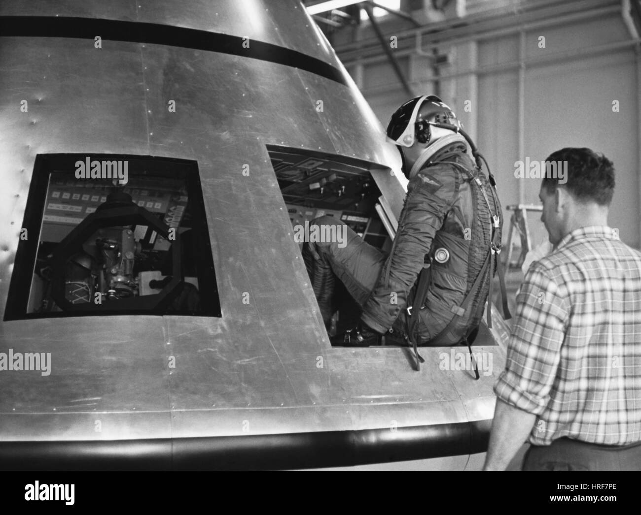
The enigmatic Ames Research Center’s “preliminary mock-up” Apollo spacecraft. Few photos and even less text available on it, other than the below or slight variant thereof:
“Three NASA test pilots suited in flight restraining suits prepare to enter the 3-man Apollo Spacecraft. A preliminary mock-up model 13’ wide and 12’ high.”
But wait, and not surprisingly, Aviation Week & Space Technology, via the Internet Archive website, comes through! With minor paraphrasing:
"Mockup of the Apollo command module at the National Aeronautics and Space Administration's Ames Research Center will be used primarily to determine instrument layouts for the three-man crew. The laboratory mockup, made of aluminum with a wood interior, is 13 ft. in dia. and 12 ft. high. Three Ames scientists (L - R) -- Milton Contella, Clark White and Ronald Gerdes -- simulate the crew. They are dressed in Ames-developed restraint suits from which the Apollo full pressure suit is expected to be designed."
See also:
Specifically, number 24:
www.theatlantic.com/photo/2012/05/50-years-ago-the-world-...
www.sciencesource.com/archive/Apollo-Flight-Restraining-G...
elpoderdelasgalaxias.wordpress.com/2016/02/12/apollo-earl...
78.media.tumblr.com/cfd886e1aa936897cfdd34cc73bb33f3/tumb...
www.apimages.com/metadata/Index/Watchf-AP-A-CA-USA-APHS36...
c8.alamy.com/comp/HRF7PE/test-pilot-climbs-into-apollo-mo...
www.pbagalleries.com/images/lot/1545/154524_0.jpg
Credit: PBA Galleries website
www.gettyimages.co.uk/detail/news-photo/portrait-of-three...
"Credit": Getty Images website
“Atop the National Aeronautics and Space Administration’s 365-foot-tall Saturn V facilities vehicle the Lunar Module [Command and Service Module] and escape tower are shown. Approaching the pad is the 415 foot-high arming tower being moved by a 3,000 ton crawler transporter. Preparations at Complex 39 are underway using the Saturn 500-F facilities vehicle to verify launch facilities, train launch crews, and develop test and checkout procedures.”
“Arming Tower”…hmmm…would it have still been referred to as such, in 1966?
PictionID:53809487 - Catalog:14_031018 - Title:Apollo Details: Apollo Mock Up; Overall View Date: 05/08/1961 - Filename:14_031018.tif - - Images from the Convair/General Dynamics Astronautics Atlas Negative Collection. The processing, cataloging and digitization of these images has been made possible by a generous National Historical Publications and Records grant from the National Archives and Records Administration---Please Tag these images so that the information can be permanently stored with the digital file.---Repository: San Diego Air and Space Museum
“The mating of Apollo-Saturn command module 011 and Saturn LEM Adapter at the National Aeronautics and Space Administration’s Manned Spacecraft Operations Building, Kennedy Space Center, Fla. The National Aeronautics and Space Administration’s Apollo-Saturn 202 mission will verify performance of the Saturn IB, the Apollo spacecraft command service module systems and the ablative heat shield. Launching will be from Complex 34, Cape Kennedy, Florida and will be the third launching in NASA’s S-IB series.”
“Aerojet-General Corporation artist’s concept shows how the Apollo spacecraft’s Service Module engine will look firing during night flight. Coloration of the Service Propulsion System thrust chamber and skirt shows temperature ranging from 5000°F. at the chamber throat to 1200°F. at the skirt extension after a few seconds of engine operation. Glass filament is used in the thrust chamber area. The engine skirt is formed of titanium and columbium. Aerojet’s SPS develops in excess of 20,000 pounds of thrust, making it America’s largest and most powerful spacecraft rocket engine. The Service Propulsion System, produced for NASA’s Apollo spacecraft under contract to North American Rockwell Space Division, is capable of providing more than 35 separate firings of varying duration.”
~7.5” x ~9.25”. Photo has been trimmed by some well-intentioned buffoon in the past.
Compare/contrast. Note that the respective glowing (hotter?) areas of the two engine nozzles are inverted. I would’ve expected them to be somewhat similar. Interesting:
mobile.twitter.com/SpaceX/status/1076838618692493313/photo/1
Credit: SpaceX
Check this one out. No idea what the engine is and obviously not in flight, yet another totally different appearance:
qph.c7.quoracdn.net/main-qimg-099ffe22085d444e4d61a6c61a9...
Credit: Quora website
The artist appears to have used the Impasto painting technique for the overall scene, with the CSM & SPS plume painted “normally”.
I think this is the work of George Mathis.
Very nice North American Rockwell artist’s concept – looking across northern Florida and the eastern seaboard - of an Apollo Command/Service Module (CSM) departing the Skylab Orbital Workshop (OWS).
Based on the similarities between this and several other artist’s concepts of this ‘scene’, in which the signature is visible, I think this is by Manuel E. Alvarez. Or Bert Winthrop maybe?
Excellent overhead view of Ground Test Vehicle/ Command & Service Module (CSM) 008, aka FRM-008, aka S/C 008, possibly/apparently being exposed to simulated illumination & thermal conditions in Vacuum Chamber A of the Space Environment Simulation Laboratory (SESL)/Bldg 32, Manned Spacecraft Center (MSC), Houston, Texas. One of three (I think) - two opposing on the sides/one overhead - banks of carbon arc lamps seem to be on. I don’t know what photography from this perspective was available when the chamber was sealed…so I have no idea if this was while the spacecraft was under vacuum conditions or not. This may be a test of the lights, system, etc. Who knows.
~7.75” x 10”. Despite being trimmed, unevenly, by some ‘blessed’ soul, a really cool photo.
Informative reading:
www.collectspace.com/ubb/Forum29/HTML/001089.html
Credit: collectSPACE website
www.drewexmachina.com/2016/10/26/the-apollo-flights-to-no...
Credit: DrewExMachina website/Andrew LePage
www.popsci.com/how-nasa-goes-to-space-without-leaving-earth/
Credit: Popular Science online website
Excellent:
Spectacular often reproduced view, which I believe shows the opposing bank of lights illuminated:
Both above credit: Internet Archive website
Spectacular view from nearly the top of the Launch(er) Umbilical Tower (LUT), of the Mobile Service Structure (MSS) likely moving back from the SA-500F facilities verification vehicle at Launch Complex 39A.
Pathetically, this otherwise spectacular photograph is reversed left-to-right.
pictionid60385312 - catalog08002036 - title: Apollo escape tower test launch - filename0802036.tif---Image from the SDASM Curatorial Collection.Note: This material may be protected by Copyright Law (Title 17 U.S.C.)--Repository: San Diego Air and Space Museum
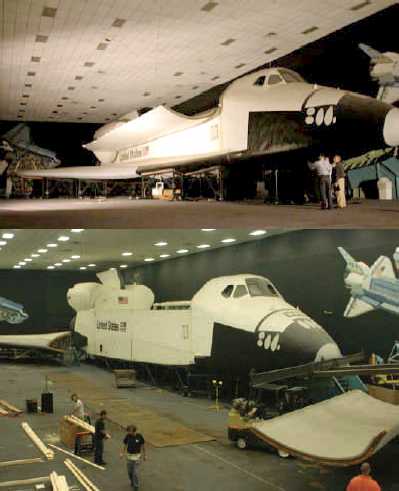
An excellent view of Space Shuttle mockup "Inspiration" - along with Apollo 14 Command Module "Kitty Hawk" - on display in the Design Engineering Implementation (DEI) room of Rockwell International's Downey plant.
An excellent observation of this particular mockup design, per the "JACQMANS SPACEFLIGHT HISTORY" website:
"As you can see...the mockup still has the original design concept for the OMS engines, i.e. a fairing for the OMS pods extended onto the aft payload bay doors. This design was abandoned very early in the development phase and the pods were designed to be fully self contained and located aft of the payload bay doors. And also the forward RSC thrusters are protected by doors."
Additionally, note the mural behind, and to either side of the orbiter, by Rockwell International’s eminently talented artist, Ted Brown. The work is a larger variant of his masterpiece, “Space Products”, which at one time (but no longer?), was prominently displayed in the Launch Control Center (LCC), Kennedy Space Center (KSC).
Check out all of the other wonderful photos of this particular display configuration:
www.disneylicenseplates.com/RSDSC/RSDSC_DEI_Inspiration.html
Credit: Disney License Plate/Rockwell Space Division Stamp Club website
An excellent reference to the mockup and - to an extent - its history, specifically, page 6:
static1.squarespace.com/static/56c78acd0442626b2590f5ea/t...
Credit: Aerospace Legacy Foundation
See also:
members.tripod.com/airfields_freeman/CA/Downey_CA_undated...
Credit: Abandoned & Little-Known Airfields: California: Central Los Angeles Area/Paul Freeman
Along with:
www.angelfire.com/fl/Jacqmans/downey.html
Credit: JACQMANS SPACEFLIGHT HISTORY website
Finally, as is all too often the case, beseeching in order to try to preserve history:
www.airspacemag.com/daily-planet/theres-one-more-shuttle-...
Credit: Smithsonian Air & Space website
en.wikipedia.org/wiki/Space_Shuttle_Inspiration
Credit: Wikipedia
A view of the heat shield on the underside of the #Apollo 16 command module at the U.S. Space & Rocket Center, #Huntsville AL
22.08.2018 11:06 CDT
24mm 1/100 sec f/8.0 ISO 800
“20th CENTURY SPACE TRAVELERS STILL NAVIGATE BY STARS
An optics technician at the Kollsman Instrument Corporation plant in Syosset, N.Y., fits cover on head of sextant part of Kollsman sextant-telescope that Apollo 8 astronauts will use to insure accuracy of the guidance and navigation system of spacecraft during its moon voyage in late December. The small instrument at right is the scanning telescope. The two celestial instruments make up the Optical Unit Assembly which fits in the wall of the command module.”
High-angle view of S/C-012 Command Module, looking toward -Z axis, during preparation for installation of the Crew Compartment Heat Shield, showing mechanics working on Aft Bay.
Credit: NASA
Image Number: S66-41851
Date: April 17, 1966
I was on travel and missed a couple of weeks posting in my "Night at the Museum" series. This photo is of the Command Module, which returned three astronauts to earth and contained the equipment and systems for reentry and splashdown. A series of parachutes opened at 24,000 ft (7.3 km) and 10,700 ft (3.3 km) and slowed the vehicle to 22 mph (35 km/h) at splashdown into the ocean.
“High angle view of BP-15 showing sling attached.”
A wonderful highly detailed photograph. As in my previous post of another photo of this boilerplate capsule, some of the signatures (of North American Aviation employees I presume) are tantalizingly, frustratingly actually, nearly legible.
Speaking of such, since the apex of the forward heat shield was entirely white at launch…were they ‘painted’ over? The surface definitely has the look of something intended to be heat resistant, maybe even ablative?
This North American Rockwell artist's concept depicts the Apollo 13 Lunar Module (LM) descending to the Fra Mauro landing site as the Command and Service Module (CSM) remains in lunar orbit. Astronaut Thomas K. Mattingly II, the command module pilot, was to photograph the LM's descent from the CSM. For what was to be NASA's third lunar landing mission, astronauts James A. Lovell Jr., commander, and Fred W. Haise Jr., lunar module pilot, were to descend in the LM to explore the Moon.
Mattingly was bumped from the crew three days before launch after being exposed to German measles, with backup command module pilot John "Jack" Swigert taking his place.
Apollo 13 launched on April 11, 1970, with little fanfare. But two days into the mission, an oxygen tank onboard exploded, transforming Apollo 13 into a tense rescue mission that hinged on the ingenuity and grit of the crew, mission control, and NASA engineers.
Credit: NASA
Image Number: S70-31898
Date: March 20, 1970
A crop, with minor editing, of the referenced photograph. Within the numbered yellow rectangles are stamped/stenciled serial/identification numbers on the forward hatch docking tunnel, also referred to as the ‘access cylinder assembly’ in another NASA document.
No two Command Modules (CM) have these applied in the same locations…believe me, I exhaustively screened photographs of every manned CM from Apollo 7 to Apollo 15. I didn’t check Apollo 16 or 17, since I figured CM-113 & CM-114 were probably not yet even a gleam in some young NAA engineer’s eye as of January 24, 1967. For additional reference & context, I also marked with the red line, the edge of what appears to be the extensive application of duct tape within the forward compartment of CM-103.
To further (eventually) plunge down the rabbit hole, the red arrows point to innocuous looking components/structures that are actually fascinating & key to distinguishing between Block I and Block II CMs. However, that’ll require posting additional imagery - at a later date.
The additional linked photographs below confirm the identification.
Grumman Aircraft Engineering Corporation (GAEC) print/artwork, ca. 1967, depicting Lunar Module ascent stage and North American Aviation (NAA) Command/Service Module rendezvous & docking.
North American Aviation (NAA) personnel/Great Americans pose with an early (Block I) Apollo Command Module mockup, most likely at NAA's Downey plant.
The three gentleman immediately to the right of the lady with her eyes partially closed, all look very familiar. Not that that means anything.
One of five enlargements from a small sheet of Japanese space-themed stamps or labels from the 1960s or 1970s. See also:
PictionID:53809468 - Catalog:14_031017 - Title:Apollo Details: Apollo Mock Up; Command Module-Exterior Date: 05/08/1961 - Filename:14_031017.tif - - Images from the Convair/General Dynamics Astronautics Atlas Negative Collection. The processing, cataloging and digitization of these images has been made possible by a generous National Historical Publications and Records grant from the National Archives and Records Administration---Please Tag these images so that the information can be permanently stored with the digital file.---Repository: San Diego Air and Space Museum
La recremada pell del Apolo 10 mostra l'infern de la reentrada a l'atmosfera terrestre. L'Apolo 10 fou la darrera missió del programa Apolo abans de l'arribada a la Lluna amb l'Apolo 11, i com a tal, fou una recreació quasi general, pel que aquesta càpsula donà la volta a la Lluna i tornà a la terra. De fet, aquesta capsula arribà a estar a només 10 km de la Lluna.
Actualment es troba al Science Museum, Londres.
ca.wikipedia.org/wiki/Apollo_10
ca.wikipedia.org/wiki/Reentrada_atmosf%C3%A8rica
=================================================================
The scarred surface of the Apollo 10 command module it's a reminder of the savage temperatures of an atmospherical entry. This was the last mission before the Moon landing by the Apollo 11, so they did a general rehersal of the latter mission, without the actual Moon landing. But this module orbited the Moon at just 10 km. above it.
It now stands in the Science Museum, London.
An excellent view of the heavily instrumented & marked up Command Module 008 (CM-008)/Command-Service Module 008 (CSM-008), aka FRM-008, aka S/C 008 circa mid-to-late 1966, during extensive unmanned and manned thermal vacuum testing in Chamber A of the Space Environment Simulation Laboratory (SESL)/Bldg 32, Manned Spacecraft Center (MSC), Houston, Texas.
I’m usually a little pissed when photographs have been ‘chopped’ in order to frame or otherwise display them. Not in this instance…as this was probably actual ‘working’ photographic documentation that required the one white border to be removed.
Note also that the external guidance & navigation optics assembly has a plastic covering taped over it. I wonder if it was removed for/during the manned portion of testing? If the crew simulated its use…since there was nothing to actually look at, thus verifying functionality…within the chamber, it would've been pointless to take it off, right? Not to mention, risking dust & other particulate contamination.
Excellent reading at:
www.collectspace.com/ubb/Forum29/HTML/001089.html
Credit: collectSPACE website
www.drewexmachina.com/2016/10/26/the-apollo-flights-to-no...
Credit: DrewExMachina website/Andrew LePage
Other excellent views:
Both above credit: Internet Archive website
Outstanding:
www.nps.gov/articles/space-environmental-simulation-labor...
“The Mobile Service Structure (MSS) being pulled back from the Apollo 8 spacecraft.
Also seen at the top of the escape tower is the Q-ball cover. This covers and protects the Q-ball, eight openings at the top of the Launch Escape Tower. These openings lead to air data probes which gauge air pressure and temperature. As well as providing dynamic pressure (known as "Q") information during powered flight, they help determine the angle of attack of the tower during an abort event. The crew can monitor any off-axis pressure on a gauge on panel 1 normally used to monitor combustion pressure in the spacecraft's SPS engine. A switch will be thrown after the tower is jettisoned to effect this change. Dual use of instruments is common in the spacecraft as it saves weight and panel.”
history.nasa.gov/afj/ap08fj/photos/ground/19681217-s68-55...
All above per the Apollo Flight Journey website:
“APOLLO PROPULSION ROCKET - - the Aerojet Liquid Rocket Company’s Service Propulsion System engine is seen partly protruding from the Apollo’s service module, or section, during spacecraft assembly at Cape Kennedy, Florida.”
If the following description/caption - taken from the ensuing link, associated with a photograph that’s obviously of the same spacecraft, is correct - then this is the AS-204/Apollo 1 spacecraft.
“Apollo 1 Command/Service Module -- The Apollo Spacecraft 012 Command/Service Module from the Apollo 1 mission being transferred for mating with the Saturn Lunar Module (LM) Adapter No.05. The Apollo 1 mission (originally Apollo/Saturn 204) resulted in disaster on January 27th 1967 when a fire broke out in the command module during a launch pad test in which all three of the primary crew died. Astronauts Virgil 'Gus' Ivan Grissom, Edward Higgins White II, and Roger Bruce Chaffee died in the accident. An investigative board was set up to identify the cause of the fire. The final report gave detailed suggestions for major design and engineering modifications, revisions to test planning, manufacturing procedures and quality control. With these adjustments, the Apollo program became safer and successfully sent astronauts to the Moon. Photographed in the Manned Spacecraft Operations Building, Merritt Island, Florida, USA, on 3rd January 1967.”
www.sciencephoto.com/media/871508/view/apollo-1-command-s...
Credit: Science Photo Library website
Amusing depiction of Apollo 11's flight profile, exemplified by the polar projection perspective of earth. Rarely seen, especially for something like this.
No offense to Mr. Tobey; however, it’s not the crew portrait I would've chosen...but, what do I know. Certainly flattering to the crew, especially Neil...he doesn’t look a day over his Gemini 8-period ‘self’...
www.spaceimages.com/ge8nearpoph.html
I think the resemblance is uncanny:
i.pinimg.com/originals/1c/9c/3a/1c9c3ad72897f58a96044d616...
Credit: Pinterest/Zahabia Poonawala