View allAll Photos Tagged commandmodule
A slightly more descriptive ‘official’ caption, from both the 1963 & 1964 versions of this scene, both linked below:
“Artist Drawing by North American Aviation Inc. - After the third stage engine burns for the second time the Apollo vehicle is on its lunar trajectory. The adapter surrounding the LEM (Lunar Excursion Module) is separated. Next the command and services modules separate leaving the LEM attached to the third stage.”
More precisely, this depicts commencement of transposition and docking maneuvers.
Something I'd never noticed before, the LEM's porch also appears to be folded down. Interesting. To me, that is.
Artwork most likely by the supremely talented Gary Meyer.
A team of U.S. Navy swimmers assists with the recovery of the Skylab 3 Command Module following its splashdown in the Pacific Ocean about 230 miles southwest of San Diego, California. The swimmers had just attached a flotation collar to the spacecraft to improve its buoyancy. Aboard the Command Module were astronauts Alan L. Bean, Owen K. Garriott and Jack R. Lousma, who had just completed a successful 59-day visit to the Skylab space station in Earth orbit. Minutes later the Command Module with the three crewmen still inside was hoisted aboard the prime recovery ship, the USS New Orleans.
Credit: NASA
Image Number: S73-36401
Date: September 25, 1973
“By igniting the descent engine (contained in the LEM’s lower, descent stage), the separated LEM is inserted into an elliptical transfer orbit. Following cutoff of the descent engine, the LEM coasts to the low point of its descent orbit which brings the craft to within about 50,000 feet of the lunar surface, and uprange of the proposed landing site. At that time, the descent engine is refired to reduce velocity during the LEM’s descent to landing.
The LEM’s descent is automatically controlled to an altitude of a few hundred feet by a Guidance/Navigation Control System. During the final landing phase, the two-man crew selects a favorable landing site and, by manual control of the reaction control system jets (clustered at the four corners of the LEM upper, ascent stage) and the variable thrust descent engine, the craft is manipulated into the correct attitude over the landing site, and landed gently on the moon.”
The above are affixed to the verso of the photograph. Although informative, they don't describe what's depicted, which appears to be lunar orbit insertion.
“APOLLO 6 MATING---Apollo Spacecraft 020 Command Module is hoisted into position for mating with Service Module in the Kennedy Space Center’s Manned Spacecraft Operations Building. Spacecraft 020 will be flown on the Apollo 6 (Spacecraft 020/Saturn 502) unmanned, earth-orbital space mission.”
Rare photograph of an early Command Module ‘chop shop’, with two of the clean-cut thugs, posing as Honeywell Manufacturing engineers, preparing to fence the stripped components, which include both a Translation Hand Controller & Rotation Hand Controller, a Stabilization and Control System (SCS) panel, an Attitude Set & Gimbal Display panel & Velocity Change Indicator panel. Even a coveted Flight Director/Atitude Indicator (FDAI), with a street value of least $275. Fortunately, these were all Block I Command Module components, only to become obsolete and of no value within several years. What looks to be the installed Translation Hand Controller is visible through the side window, equipped with its jail cell door observation window sliding panel.
Note also the chart recorder/plotter, which looks to be placed/positioned atop some sort of shelving or similar structure in the background. Also, the elevated floodlights, angled downward & possibly attached to scaffolding. Interesting.
“RONALD CHISENHALL”. Really? Obviously, the perps got a little carried away with the alias. I suppose to not be too plain/dull/vanilla, like say Jones, Smith, Carpenter, etc.
Or, I suppose it could conceivably be associated with the following, from the February 6, 1964 entry of “The Apollo Spacecraft - A Chronology”/NASA SP-4009. In fact, it explains the components prominently “on display” in the photograph:
“Minneapolis-Honeywell Regulator Company reported it had developed an all-attitude display unit for the CM to monitor the guidance and navigation system and provide backup through the stabilization and control system. The Flight Director Attitude Indicator (or "eight-ball") would give enough information for all spacecraft attitude maneuvers during the entire mission to be executed manually, if necessary.
Honeywell News Release, "All-Attitude Display Produced By Honeywell For Apollo Spacecraft," February 6, 1964; Space Business Daily, February 24, 1964, p. 290.”
At:
www.hq.nasa.gov/office/pao/History/SP-4009/v2p2c.htm
Finally, as I’m sure at least one of you is wondering, what is this Command Module designated as? A ‘boilerplate’ I think.
A very nice North American Rockwell artist’s depiction of the docked CSM/OWs configuration in earth orbit. The year is pretty much a SWAG based on the appearance of both the OWS & CSM. Minor details, to include no evidence of a MDA radial docking port and high fidelity of CSM details may support such. Then again, maybe not.
Wonderful artwork by Donald W. Bester.
“Artist Drawing by North American -- After the final flight path adjustments have been made to assure hitting the 40-mile re-entry corridor the Service Module is discarded.”
This series of Apollo mission ‘milestones’, gorgeously rendered by Gary Meyer on behalf of NAA, may be the final/next to final. The high-gain antenna is representative of the final configuration, it’s a Block II Command Module (CM), and the scimitar antennas, originally incorporated into the pronounced CM strakes, subsequently downsized to the ‘half-moon” disks, although still attached to the CM, are seen here (one of them, that is) in their final location, on the Service Module.
“NASA Apollo Spacecraft — Re-entry
Space and Information Systems Division
North American Aviation, Inc.”
Above per the larger presentation/portfolio print version of the image & linked to below.
One of Gary Meyers’ earliest NAA/NASA works, as part of an illustrious & diverse career.
garymeyerillustration.net/ILLUSTRATIONS/Pages/early_work....
Credit: GARY MEYER ILLUSTRATION website
Rest In Peace Mr. Meyer, THANK YOU.
“The Apollo Command Module for the uprated Saturn I 204 flight has been transferred from the Pyrotechnic Installation Building at the Kennedy Space Center on Merritt Island to the Manned Spacecraft Operations Building, following initial receiving and inspection checks. It is currently undergoing further checkout tests in the High Bay area of the MSO Building.”
CM-012 = NAA death trap for Grissom, White & Chaffee
In August 1967, the Saturn V vehicle (SA-501), rolled out to the launch pad in preparation for its first launch. The vehicle was designed by engineers at NASA's Marshall Space Flight Center in Huntsville, Ala. for the first human missions to the moon. The 363-foot-tall rocket rolled out from the Vehicle Assembly Building on a crawler and slowly moving at 1 mph made its way to the launch pad at the Kennedy Space Center (KSC) in Fla. The Apollo 4 mission was an uncrewed test flight designed to obtain flight information on launch vehicle and spacecraft structural integrity and compatibility, flight loads, stage separation, and subsystems operation including testing of restart of the S-IVB stage, and to evaluate the Apollo command module heat shield. The Apollo 4 was launched on November 9, 1967 from the Kennedy Center and completed a successful mission.
Image credit: NASA/MSFC
Original image:
www.nasa.gov/centers/marshall/history/gallery/Saturn_V_fo...
More Marshall history images:
www.nasa.gov/centers/marshall/history/gallery/marshall_hi...
_____________________________________________
These official NASA photographs are being made available for publication by news organizations and/or for personal use printing by the subject(s) of the photographs. The photographs may not be used in materials, advertisements, products, or promotions that in any way suggest approval or endorsement by NASA. All Images used must be credited. For information on usage rights please visit: www.nasa.gov/audience/formedia/features/MP_Photo_Guidelin...
Official North American Aviation (NAA) documentation photograph of an early (1963) itty-bitty (~3.5” diam.) model of the Apollo Command Module (CM). I would’ve assumed a model this small to have been used in wind tunnel testing. However, I’m pretty sure those were normally machined & unpainted.
This bears decals & even the outline of the hatch. This may be the first photograph I've come across that depicts strakes on a Command Module model, early artist's concepts being way more prevalent.
The photo was obviously meant for internal consumption, although apparently released to Raytheon for limited distribution.
Really cool & rare…but why so small? Its ‘presentation’ reminds me of how returned lunar samples were photographically documented. Interesting.
8.5” x 11”.
Based on the similarity of the overall view, the photo number & date, I presume this to be another fantastic view of Command Module 103 (CM-103) during assembly & testing at North American Aviation’s (NAA) Downey, CA facility. Possibly bldg. 290?
The dangling hoses from the fixture partially encircling the Command Module are all pneumatic, and interestingly - to me that is - five of them appear to lead into the spacecraft through the hatchway. In the companion photograph to this, they are hooked up to tanks/vessels visible within the exposed aft compartment, all Reaction Control System (RCS) related. So, I assume/d this ‘work station’ was to pressure test those tanks/vessels. If so, I wonder what pneumatic/high pressure, possible RCS connections are inside the crew cabin. Or maybe access to them is through the flooring? IDK, total SWAG.
Also, what I initially thought was the framework of the surrounding structure are the myriad of feed lines to each hose position!
Additionally, per an ‘H-Missions’ Command/Service Module News Reference, at:
www.hq.nasa.gov/alsj/CSM16_Reaction_Control_Subsystem_pp1...
which may or may not be applicable (I choose to think it is):
“The [CM reaction control] system consists of two independent, redundant systems, each containing six engines, helium and propellant tanks, and a dump and purge system. The two systems can operate in tandem; however, one can provide all the impulse needed for the entry maneuvers and normally only one is used.”
Note when compared to the companion photograph, which is of the opposite side of the capsule, the complete absence of any tanks. I first thought they had yet to be installed – WRONG, as shown in this very illustrative diagram.
Splitting the following diagram right down the middle; the right-hand side is what’s visible in this photograph & the left-hand side being what’s visible in the companion photograph:
sites.google.com/site/theapolloconnection/_/rsrc/14727686...
Credit: “The Apollo Connection” website
I ignorantly would’ve expected the components to be more equally distributed. I’m sure the placement/positioning is associated with weight/mass distribution, center of gravity & other possible ‘asymmetric’ properties of the CM. Fascinating.
A rare, obscure & stunning photograph that somehow fortunately survived.
“Apollo 104 command and service modules arrive at Kennedy Space Center from the skid strip on Cape Kennedy. Scheduled for the second manned Saturn V flight, the spacecraft was flown from the manufacturer’s plant in California. The printed sign says “Good luck again Jim, Dave and Rusty – 104 opens the door,” referring to astronauts James McDivitt, David Scott, and Russell Schweickart, who will fly the mission scheduled for this December.”
Pertinent, interesting & informative discussion:
www.collectspace.com/ubb/Forum29/HTML/001889.html
Credit: collectSPACE website
A dramatic view of heavily instrumented Command Module 008 (CM-008)/Command-Service Module 008 (CSM-008), aka FRM-008, aka S/C 008 circa mid-to-late 1966, during extensive unmanned & manned thermal vacuum testing in Chamber A of the Space Environment Simulation Laboratory (SESL)/Bldg 32, Manned Spacecraft Center (MSC), Houston, Texas.
The photograph appears to have been taken through an observation window, apparently/obviously(?) mid-test.
Excellent reading at:
www.collectspace.com/ubb/Forum29/HTML/001089.html
Credit: collectSPACE website
www.drewexmachina.com/2016/10/26/the-apollo-flights-to-no...
Credit: DrewExMachina website/Andrew LePage
Other excellent views:
Both above credit: Internet Archive website
Outstanding:
www.nps.gov/articles/space-environmental-simulation-labor...
Credit: National Park Service website
“APOLLO 204 CREW TESTS -- Prime crew for the National Aeronautics and Space Administration’s first manned Apollo mission (204) prepare to enter their spacecraft inside the altitude chamber at the Kennedy Space Center. Entering the hatch is Astronaut Virgil I. Grissom, commander. Behind him is Astronaut Roger B. Chaffee. Standing at left with chamber technicians is astronaut Edward H. White II.”
JANUARY 27, 1967
Compare/contrast with the caption associated with the linked color image below:
“The Apollo 1 prime crewmembers for the first crewed Apollo Mission (AS-204) prepare to enter their spacecraft inside the altitude chamber at the Kennedy Space Center (KSC). Entering the hatch is astronaut Virgil I. Grissom, commander; behind him is astronaut Roger B. Chaffee, pilot; standing at the left with chamber technicians is astronaut Edward H. White II, senior pilot.”
The reason for the obvious difference:
“In the spring of 1967, NASA's Associate Administrator for Manned Space Flight, Dr. George E. Mueller, announced that the mission originally scheduled for Grissom, White and Chaffee would be known as Apollo 1, and said that the first Saturn V launch, scheduled for November 1967, would be known as Apollo 4. The eventual launch of AS-204 became known as the Apollo 5 mission. No missions or flights were ever designated Apollo 2 or 3.”
At:
www.nasa.gov/mission_pages/apollo/missions/apollo1.html
Additionally, in-depth, highly informative Apollo numbering convention discussion available at the following:
www.collectspace.com/ubb/Forum29/HTML/000909.html
Credit: collectSPACE website
Finally, although I can find nothing to support it, I believe the gentleman between White & Chaffee is suit technician Joe Schmitt, who passed away September 25, 2017 at the age of 101:
historycollection.jsc.nasa.gov/JSCHistoryPortal/history/o...
REST IN PEACE ALL. THANK YOU.
“APOLLO REENTRY TEST--Illustration shows how unmanned Apollo spacecraft command module enters atmosphere (left) at 19,451 miles an hour travelling west to east about 79 miles above Australia (map inverted) in return from earth orbit. First, reaction control rockets fire to jettison service module (right); command module, now in free flight, is pitched over and roll engines position command module for entry. Heat shield ablates (boils away) keeping interior cool. Touchdown is near Wake Island. Test, scheduled not before August 25, will be second in Apollo program to land U.S. Astronauts on the moon. Apollo spacecraft command and service modules are produced by North American Aviation’s Space Division for NASA’s Manned Spacecraft Center.”
This might be one of the most meticulous depictions of a major land mass, Australia in this case, along with Papua New Guinea. With no clouds, interesting. No idea by whom.
The alphanumeric designation on the verso was likely the identification used in pre-mission NAA document(s), such as a press kit.
“With a minor investment, but exercising a bit of ingenuity, the United States may have a large space station orbiting the earth before the end of 1968. A decision to build on a capability NASA presently possesses may provide a cylindrical container with a capacity of about 12,000 cubic feet for use as a laboratory to pursue significant space experiments for a minimum of 30 days.
Success in this venture may pave the way for the establishment of a permanent space station with a crew always in attendance.
The breakthrough in the development of the space station came with the realization that, with the launching of the giant two-stage Saturn I. booster, the second (or S-IVB stage) will provide an empty cylindrical fuel tank 58 feet long and 21 feet in diameter when it is in orbit. This cylinder is divided into two compartments for the hydrogen fuel and oxygen oxidizer.
It is the 29-foot-long hydrogen tank which will be pressurized, to create the space station. It will serve as a laboratory with a shirt-sleeve environment for both astronauts and scientists.
At present, plans call for a launch of the Saturn I. rocket system before the end of 1968. This will provide the initial velocity to the S-IVB stage, together with the Apollo command service module. When the S-IVB stage has completed firing, it will have achieved an elliptical orbit with a perigee, or low point, of 93 miles and an apogee, or high point, of about 200 miles. Once in orbit, the astronauts will disconnect the Apollo spacecraft and turn it around to link up with the S-IVB stage. When the service module engine fires, it will circularize the S-IVB orbit at about 200 miles. At this altitude, the spacecraft will be in no danger of re-entry for the required 30-day mission.
While it appears that very little additional work must be performed, in reality a…”
Yet ANOTHER work by the prolific John Gorsuch.
An excellent view of the U. S. Space Park, at the 1964/65 New York World’s Fair.
Sites abound with additional information and photos. For something off the beaten path:
www.collectspace.com/ubb/Forum18/HTML/001194.html
Credit: collectSPACE website
Within the photograph, I can make out two placards/sandwich board like things with the patch/logo.
“Illustration shows communications systems developed by RCA for use by astronauts who will land on the moon. Backsets will permit men to talk to one another while other systems permit talk between spacecraft and earth, and astronauts and spacecraft.”
I remember seeing this – a lot – in newspapers of the time. Note the Astronaut on the right appears to have a "Jacob's staff", possibly instrument laden, in hand, while the Astronaut in the crater is using a hand trowel to place lunar samples into a collection bag. The depiction of both leads me to believe this was originally created prior to 1969.
Maybe by James T. Burns? Regardless, wonderful information regarding Mr. Burns, with other works, to include supporting ‘evidence’ for my aforementioned assertion:
www.hq.nasa.gov/alsj/alsj-JamesBurns.html
www.hq.nasa.gov/alsj/4-Lunar-Communications.jpg
Both above credit: ALSJ website
The command module was the living quarters for the three-person Apollo 11 crew during most of the first manned lunar landing mission in July 1969.
#apollo11 #space #lunarlanding #nasa #kennedyspacecenter #astronaut #saturnV #rocket #thefinalfrontier #commandmodule
“This drawing, looking over the shoulder of command pilot Walter Schirra, shows approach of the Apollo 7 module and its third stage booster in rendezvous exercise. Sighting device is lighted reticle projected on window by instrument above.”
The 'instrument' is the Crewman Optical Alignment Sight (COAS). Interestingly, very little is available, both in images & text, pertaining to the one used within the Command Module. Understandably, the analogous COAS used inside the Lunar Module is by far more 'popular'.
history.nasa.gov/afj/ap13fj/pics/coas-diagram.jpg
Credit: Apollo Flight Journal website
Despite being really into Apollo photos, I'm not all that familiar with the CM's instrument panel(s), however; the depiction appears to be pseudo-accurate, albeit greatly simplified.
7.75" x 9.375".
Fortunately, yet another unique, creative & unexpected Arasmith find.
A full life:
www.dignitymemorial.com/obituaries/westminster-ca/russell...
Credit: Dignity Memorial website
Thank You Sir, Continue to Rest In Peace.
An engineering test unit from Bell Aerospace in 1965. It provided Monomethylhydrazine (MMH) fuel to the spacecraft's twelve Rocketdyne SE-8 Reaction Control System (RCS) engines used for attitude control. A similar tank was used to store the oxidizer (N204 ) which was combined and ignited upon contact with the MMH. This is a hypergolic fuel system which does not require any separate ignition system.
Titanium MMH tank, with various valve connections (diagram below). Helium pressurizing gas pushed against flexible bladders in the fuel and oxidizer tanks to force the weightless propellants out of the tanks.
From the Spaceaholic post on the oxidizer tank (the compliment to this tank): "The tank incorporates an integral bladder for positive expulsion. Positive expulsion systems were necessary to provide continuous propellant flow to the engines regardless of vehicle position, environmental and dynamic forces, or zero gravity conditions where the propellant tended to float in the tank and cling to the tank wall instead of flowing naturally toward the tank outlet.
Propellant is contained within the bladder. A pressurizing port is provided on the tank shell and a propellant outlet port and liquid bleed tube are incorporated in the diffuser assembly. The propellant is loaded into the bladder through the propellant outlet port. When the bladder is full, helium, supplied by another onboard Command Module tank, was applied to the pressuring port of the tank to pressurize the area between the tank shell and the outside of the bladder. The pressurizing gas caused the bladder to collapse around a diffuser tube (which runs from the propellant outlet down through the center of the tank) and the propellant was expelled through the outlet port."
The metal tag reads (from photo below):
TANK MMH POSITIVE EXPULSION
Manufactured 6-2-65
Contract NAS9-150 (indicates Apollo CSM)
NAA (North American Aviation) Control Number: ME282-0007-0001
Serial Number 8
Max Working Pressure: 360 PSIG
Proof Pressure: 480 PSIG
Burst Pressure: 540 PSIG
An artifact from the Future Ventures’ 🚀 Space Collection.
1965. Apollo Program. Grumman Aircraft Engineering Corporation (GAEC). Lunar Excursion Module (LEM). Powered Descent. Craig Kavafes.
Striking, and to me, iconic.
Fortunately, in this instance, the NASA photo processing person, section, department…whatever he/they were called, ‘framed’ the image so as to retain the CSM in the upper left corner. Yay!
This being the 1965 update/revision, the background has understandably remained the same, albeit with the “2/64” date of the original(?) rendition (linked below) painted over by Mr. Kavafes.
Note also the ‘doubled’ ladder, it being hinged at the bottom & folded up. It’s seen deployed in photo no. 651091, despite it appearing to have been totally unnecessary.
I love it, but I don’t get it.
“Spacesuits and computers were used in combination with a simplified mockup of NASA's Apollo moonship (background) at the Aeronautical Division of Honeywell in Minneapolis, where the stabilization and control system for the three-man spacecraft was developed. In the photo engineer Bill Summers (left) made final adjustments on one of a number of computers which would feed simulated flight information to engineer-test pilot Jim O'Neil (right) when he was inside the command module mockup.
--Minneapolis-Honeywell photo”
Despite the “sepiation” of a large portion of the photograph, it’s wonderfully vivid, sharp, glossy & detailed…absolutely delightful.
A wonderful & unexpected surprise, the above description, along with the image is at the following (Adobe Acrobat page 202, of 297):
history.nasa.gov/SP-4009vol2.pdf
If the following information/identification is correct, Mr. O’Neil appears (to me) to be wearing a Mark IV full pressure suit, manufactured by Arrowhead Manufacturing Company (as a competitor to the B.F. Goodrich suit):
airandspace.si.edu/collection-objects/pressure-suit-mark-...
And:
www.si.edu/object/helmet-flying-full-pressure-mark-iv-uni...
Both above credit: Smithsonian NASM website
Additionally, pertaining to the Mark IV image:
"This is a United States Navy Mark IV high altitude pressure suit. The Arrowhead Products Company made this suit in the mid-1950s at the request of the Navy as a competition suit. The B. F. Goodrich Company made a similar suit that the Navy later adopted as it as its emergency pressure suit., One interesting feature of this suit is the use of the molded rubber convolutes in the joints. These joints allowed pilots greater mobility in the arms, legs and waist than previous suits and were lighter weight, too. However, they were hard and uncomfortable for pilots while sitting in the aircraft cockpit. Nevertheless, NASA obtained this suit from the Navy during the course of evaluating pressure suits to turn into spacesuits for the Mercury program. Even though NASA opted to use the B.F. Goodrich design for Mercury, they kept the convolute joint in mind and selected the ILC Industries as the contractor for Apollo suits when that company proposed a similar joint system., NASA transferred this suit to the Museum in 1975."
At:
www.omnia.ie/index.php?navigation_function=2&navigati...
Credit: OMNIA website
Last, but certainly not least. And I may be reaching; however, could this possibly be the same Jim O’Neil??? To me, the eyes, nose, even filtrum & upper lip contour look to be of the same person. Although the timeline of his biography doesn’t fully support such, he was in a staff position at this time…so maybe?:
www.veterantributes.org/TributeDetail.php?recordID=996
Credit: Veteran Tributes website
Command Module Pilot Ronald Evans holds up a soup package, inside the Command Module. Image taken during the Apollo 17 mission on the Trans-Lunar Coast (TLC). Original film magazine was labeled SS. Film type was SO-168, High Speed Color Interior (CIN) Ektachrome EF, high speed color reversal, ASA 160, 55mm lens.
Credit: NASA
Image Number: as17-162-24083
Date: December 11, 1972
“MOTHER SHIP – Artist’s drawing shows the Apollo “mother ship” as it may look in orbit around the Moon just before the three Houston astronauts return to Earth. The three men sit in the pointed “command module” or cabin. Behind them is the “service module” that contains the huge rocket that will fire them away from their Moon orbit and return them to Earth. Near Earth the cone-shaped command module will be separated from the service module, and the astronauts will fall to Earth in their three-man cabin.”
Note the large strake - even casting a shadow – on the exterior of the Command Module. To me, the crew looks to be near earth, but hey, earth/moon, whatever...close enough for government work, right?
Unfortunately, there's no signature. However, 1963/NAA would suggest Gary Meyer, in addition to the strong similarity to at least two other works, to include the ‘cut’ pattern of the cutaway views... one of those conclusively identified as Mr. Meyer. I'm counting this as another ‘WIN’!
The verso bears alpha-numeric identification similar to that used by North American Aviation/Rockwell, for the illustrations featured in this latter news/press publication. So I’m assuming this image was possibly used in some earlier similar documentation:
cdn2.hubspot.net/hubfs/413105/Apollo%20Press%20Kits/North...
The parent site to the above…likely from the which the above link can be better reached:
www.apollopresskits.com/apollo-presskit-directory
Credit: David Meerman Scott
As an aside, I do believe Mr. Scott used this photo (far left panel) of mine in his splash page:
www.flickr.com/photos/146423059@N02/46528010321/in/album-...
At first glance this looks to be an excellent perspective view of transposition & docking, complete with jettisoned SLA panels drifting off, by North American Aviation (NAA), responsible for many Apollo artist’s concepts during this (1963) time frame. The depiction very possibly by the phenomenally talented Gary Meyer.
Although dated 1963, the photo depicts an early LEM design of NASA origin, which predates even the initial GAEC concept. Note the cylindrical descent stage, wide stance landing gear, and although not visible, a probable conical ascent stage.
Since when is this CSM/LEM configuration/positioning normal? Especially AFTER the S-IVB stage has been jettisoned. And what is that conduit-like thing coming out from the Service Module, running along its length, apparently to/into the LEM?
Well I’ll be damned, commencing at the 1:52 mark:
Credit: The Space Archive/YouTube
Credit: Retro Space HD/YouTube
Who knew?! Did you!? I didn’t!
In color:
Credit: Internet Archive website
Command module recovered after splashdown of the Apollo 14 mission, I think on loan from the Smithsonian to Kennedy Space Center.
PictionID:53813401 - Catalog:14_031284 - Title:GD/Astronautics Models Details: Apollo Model; Mission with Retro Rocket-Showing Engines Date: 05/14/1961 - Filename:14_031284.tif - - Images from the Convair/General Dynamics Astronautics Atlas Negative Collection. The processing, cataloging and digitization of these images has been made possible by a generous National Historical Publications and Records grant from the National Archives and Records Administration---Please Tag these images so that the information can be permanently stored with the digital file.---Repository: San Diego Air and Space Museum
“Artist concept of “Moon Mission”.
Yet again…GOOD GRIEF & UGH.
More than likely this depicts a trans-earth midcourse correction burn of the SPS engine.
A gorgeous work assuredly by the immensely talented Gary Meyer, on behalf of North American Aviation (NAA). The image is most commonly seen in its beautiful color lithograph version published/issued by NAA.
“Apollo 13 launch to lunar surface:
1. Apollo XIII emblem and the astronaut crew (left to right); Thomas K. Mattingly; James A. Lovell; and Fred W. Haise.
2. Astronaut prepares to enter the Apollo Command Module prior to launch.
3. Launch from Complex 39A Kennedy Space Center, Florida.
4. Lunar Module lands on Moon.
5. Astronaut Fred Haise prepares to deploy ALSEP.
6. Astronaut Fred Haise carries the ALSEP experiment to its deployment location away from Lunar Module.”
Although I’ve been unable to find a single “match”, these look like the work of Paul Calle, I think.
In lieu of an informative caption, and it being a unique/odd scene, I propose:
Two F-4 ‘Phantom’ fighter aircraft provide close-air support after the emergency touchdown of an Apollo capsule in the Kazakh Steppe region of the Soviet Union. Earth Landing System ensured crew survival, who were then exfiltrated to West Germany.
Tongue-in-cheek of course, but why else would F-4’s be screaming past an Apollo command module at touchdown? Pretty impractical for recovery operations, so…what else is there? Purely artistic license? So, with that, this is the first & only artist’s concept of an Apollo touchdown/splashdown/recovery (that I’ve come across) that features fixed-wing aircraft.
I don’t know if the capsule’s base, visible between the expanding dust/dirt plumes, is the paint scheme, or maybe a footpad or some other sort of landing attenuation system. If there are fighter jets flying by at tree-top level, anything’s possible! So, a SEAL team is probably enroute, ETA 12 minutes. 👍
Although a rather implausible scene, it is well rendered...from the aircraft themselves, the collapsing parachutes, to the very realistic dust plume. Thus, along with the year & the depiction of a NAA-manufactured craft, I again submit the artist to be Gary Meyer.
Apollo Splashdown--Permann Collection Image--Please tag these photos so information can be recorded.---Note: This material may be protected by Copyright Law (Title 17 U.S.C.)--Repository: San Diego Air and Space Museum
Based on the date stamped on the verso, the day after the flight/mission, the vehicle is likely Apollo 4, depicted during ascent, propelled by the single J-2 engine of the S-IVB stage.
Stylistically, and with the often-recurring numbering in the corner of the photo, this is likely another lost/forgotten? gem by Russell Arasmith. Although a slightly less polished, less detailed effort when compared to latter renderings. Possibly due to being early/earlier during Mr. Arasmith’s incredible career? And combined with maybe less available imagery to work with, this being the first launch of the Saturn V rocket.
Obviously one of a series, although a little odd that this phase of the flight would be labeled no. 1. I just need to ‘shut up’ & not look a gift-horse in the mouth…this is a win.
A full life:
www.dignitymemorial.com/obituaries/westminster-ca/russell...
Credit: Dignity Memorial website
I'm sure only a fraction:
www.nasa.gov/centers/marshall/history/arasmith-gallery.html
A wonderful peak, confirming my above statement:
d3eguztg5751m.cloudfront.net/as/assets-mem-com/cmi/7/7/9/...
&cropxunits=619&cropyunits=464&maxwidth=650)
Credit: The Arasmith Family/Dignity Memorial website
“APOLLO RENDEZVOUS—Apollo 9 spacecraft command and service modules hold position as Lunar Module Pilot Russell L. Schweickart maneuvers ascent stage to first manned rendezvous and docking in program. The rendezvous and docking, shown in this illustration by North American Rockwell’s Space Division, depicts event as it will take place over moon in actual lunar landing flight slated for July. Mothership command and service modules are produced for NASA by North American Rockwell’s Space Division, Downey, California.”
Note the nearly opposing shadow directions cast by the two sets of service module RCS thrusters. I assume the one on the right due to earthlight. Attention to detail...I like it.
Exquisite, detailed & masterful work, as always, by resident NAA/NAR artist Henry Lozano Jr.
A WIN: Thankfully, Mr. Lozano subtly placed his signature between the circular tropical depression(?) and earth’s limb.
“The Apollo 17 Saturn V space vehicle vents liquid oxygen during the Countdown Demonstration Test for dress rehearsal for launch. The fully fueled vehicle was counted down to a mock liftoff during the “wet” portion of the test, conducted Nov. 20. After the cryogenic propellants on board the spacecraft were detanked, astronauts Eugene A. Cernan, Ronald E. Evans and Harrison H. Schmitt boarded their spacecraft the following day to participate in the “dry” portion of CDDT, which included simulated ignition and liftoff. They will be launched to the Moon Dec. 6, 1972.”
www.youtube.com/watch?v=y3KEhWTnWvE
Credit: Ahmad F Elyan/YouTube
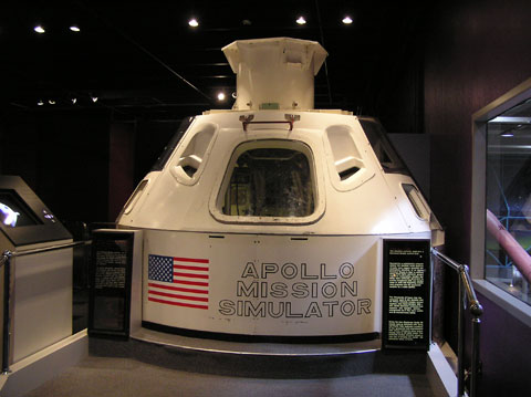
“This artist’s rendering basically concentrates upon the instructor-operator station (IOS) which is equipped to control the simulator and to monitor flight crew performance via several closed-circuit TV monitors. Virtually every indicator, control and instrument in the command module are displayed at the IOS.”
Truly a unicorn. I’ve never seen any photo, artist’s concept…ANYTHING, produced by the Link Division of General Precision, Inc., the manufacturers of the Apollo Command Module Simulator.
A far cry from the eventual “Great Train Wreck” configuration, as dubbed by Astronaut John Young. Which I find rather odd. By 1964, I would’ve expected Link Division engineers to have been aware of the expected external appearance of the simulator. Perhaps the simplified, recognizable-as-an-actual-Command-Module appearance was for aesthetics? Or…were the “train wreck” components to be removable/retractable? I didn’t think so, but who knows. I also can’t help but notice one Astronaut wearing a PLSS...huh?
Last/least, the suits worn appear to more-or-less be the ILC Apollo AX1H-022, as seen on page 21 of this excellent document:
www.hq.nasa.gov/alsj/ILC-SpaceSuits-RevA.pdf
I must confess, I wasn't aware of this simulator configuration. Interesting:
www.collectspace.com/review/gacspaceguy/smo_apollosim01.jpg
www.collectspace.com/ubb/Forum29/HTML/000978.html
Both above credit: collectSPACE website
Also:
airandspace.si.edu/collection-objects/crew-compartment-ap...
Credit: Smithsonian NASM website
However, most importantly, as if the above wasn’t enough, the artist is Robert C. “Bob” Sherry…another one in the WIN column.
Thank You & continue to Rest In Peace Good Sir.
www.askart.com/artist/Robert_C_Bob_Sherry/135335/Robert_C...
www.askart.com/photos3/2014/SWN20130124_75845/257.jpg
Both above credit: askART website
www.invaluable.com/auction-lot/robert-c-sherry-american-a...
Credit: invaluable website
Wonderful stuff & what looks to be an entertaining & enjoyable site:
unobtainium13.com/2017/04/10/artist-profile-robert-c-sher...
Credit: Through the Shattered Lens blog
"Houston. We're getting our first look at the service module now. One whole side of the spacecraft is missing. Right by the high gain antennae a whole panel is blown out, right up. Right up to our heat shield." -Tom Hanks, Apollo 13
.
.
This R2 body has served me well with several builds and is much more versatile than I would have ever imagined. It wound up being the perfect part to show the damaged Apollo 13 Service Module as seen by the crew from the Command Module after being jettisoned.
I also think this build is a personal record for the least amount of parts, a whopping 3 pieces.
PictionID:53813425 - Catalog:14_031286 - Title:GD/Astronautics Models Details: Apollo Model; Rear view of Mission Model Date: 05/14/1961 - Filename:14_031286.tif - - Images from the Convair/General Dynamics Astronautics Atlas Negative Collection. The processing, cataloging and digitization of these images has been made possible by a generous National Historical Publications and Records grant from the National Archives and Records Administration---Please Tag these images so that the information can be permanently stored with the digital file.---Repository: San Diego Air and Space Museum
“Boilerplate No. 14 Command Module on fifth level of H14-124 GSE (Ground Support Equipment) systems integration workstand Apollo Systems Integration and Checkout Facility, showing view through main access hatch of main display panel and Systems Manager’s couch. At left is seen the break-out box panel for systems checkout.”
Likely, originally a 1964 North American Aviation (NAA) documentation photograph taken at its Downey, California manufacturing plant.
Note the Block I capsule 'vertical' configuration of the pitch reaction control system thrusters directly above the hatch.
And, apparently the ‘Systems Manager” couch, aka Command Module Pilot (CMP) couch, is the only seating installed.
Per the “APOLLO SPACECRAFT FAMILIARIZATION MANUAL SM2A-02, dated 30 APRIL 1965, which is full of FANTASTIC Apollo Command Module information. DAMN:
BOILERPLATE 14/”HOUSE SPACECRAFT 1” resided at the North American Aviation (NAA) manufacturing plant in Downey, California. The boilerplate’s ‘purpose’ being a “developmental tool for use in developing spacecraft systems and preliminary checks in integrated systems compatibility.” Its ‘mission’ was as a “research and developmental tool for systems evaluation (static vehicle).” Awesome.
Above at/paraphrased from:
www.scribd.com/document/66107435/Apollo-Familiarazation-M...
Credit: Bob Andrepont/SCRIBD website…bravo!!!
Apparently, the eventual/final fate of this enigmatic ‘vehicle’ has been somewhat of a mystery:
www.collectspace.com/ubb/Forum29/HTML/001192.html
www.collectspace.com/ubb/Forum14/HTML/001177.html
Both above credit: collectSPACE website
Who knew?!
Did you?
I didn’t!
“Artists concept shows Apollo 8 spacecraft as it orbits the Moon. During this mission, the tree-man crew will photograph the Moon’s surface and make landmark sightings and other observations. Television signals may be transmitted live to Earth by the four-dish high gain antenna at the rear of the spacecraft. The mission calls for ten orbits of the Moon. The initial two orbits will be 60 by 170 nautical miles and the next eight will be 60 nautical miles circular. Apollo 8 is scheduled for launch from the NASA Kennedy Space Center at 7:51 a.m., December 21. The 147-hour National Aeronautics and Space Administration lunar orbit mission will end with splashdown in the Pacific Ocean south of Hawaii.”
Note that the depiction is a cutaway, revealing one of the crewmen photographing the lunar surface...with a camera that has a sight on it befitting a WW II anti-aircraft gun. I don't know, maybe such was planned/used?
I can’t even guess on the artist...yet, which is a shame, because this is a beautiful piece of work.
Featured as the box cover of Columbia Pictures’ 8mm “home movie”, of the mission, entitled “APOLLO 8 - MOON ORBIT”.
Note the similarity:
spaceflight.nasa.gov/gallery/images/apollo/apollo10/hires...
Credit: Apollo 10 Flight Journal website
PictionID:53813389 - Catalog:14_031283 - Title:GD/Astronautics Models Details: Apollo Model; Command Module-Clear Plastic Date: 05/14/1961 - Filename:14_031283.tif - - Images from the Convair/General Dynamics Astronautics Atlas Negative Collection. The processing, cataloging and digitization of these images has been made possible by a generous National Historical Publications and Records grant from the National Archives and Records Administration---Please Tag these images so that the information can be permanently stored with the digital file.---Repository: San Diego Air and Space Museum
“APOLLO SPACE WALKER—Astronaut Russell L. Schweickart “walks” his way to orbiting spacecraft command module hatch about 150 miles above earth in this realistic Apollo 9 mission illustration by North American Rockwell’s Space Division, principal spacecraft contractor. Two-hour EVA (Extra Vehicular Activity) begins early in the fourth day of the mission, about 73 hours after scheduled February 28 launch. Schweickart, with safety tether attached, emerges from lunar module hatchway and using handholds wends his way to command module. Cameras mounted on the command module door and lunar craft’s handrail will photograph Schweickart’s estimated 15 minute “walk” to and from the command module, using handrails along the “path”. Spacecraft mothership command and service modules were produced for NASA by North American Rockwell’s Space Division, Downey, California.”
“…in this realistic…illustration…”, the nearest thing to an ‘acknowledgement’ I think I’ve ever read in the caption of an artist’s superlative creation. The name unfortunately, per usual, is either obliterated or cropped. I’m almost certain it’s by Henry Lozano Jr., and it is totally amazing…the detail, accuracy, shadows, etc. I don't see the handrail mounted camera though. Possibly behind Rusty?
And/or, the caption from the NASA-appropriated issuance of the photo:
“North American Rockwell artist's concept illustrating a part of the planned Apollo 9 extravehicular activity on the fourth day of the mission as the Command and Service Modules are docked to the Lunar Module. The figure performing the EVA represents astronaut Russell L. Schweickart, Apollo 9 lunar module pilot.”
The scene depicted did not happen. Excellent discussion & observations of such:
www.collectspace.com/ubb/Forum29/HTML/001166.html
Credit: collectSPACE website
Interesting. And I'm totally onboard with their mission:
b612foundation.org/50-years-ago-rusty-schweickart-had-5-m...
Credit: B612 Foundation website
“Erection of Launch Escape System for Command Module 009 on Pad 34”
The exquisite resolution & detail in these early photographs is just amazing.
The large white object to the right is the white room! Is that cool or what?! And a whole lotta duct tape going on.
More ‘importantly’, having often seen them on early Block I Command Modules being prepared for flight, what the hell are those “REMOVE BEFORE FLIGHT” disks? And some/most have that central protruding HAL-like ‘eye’. What’s up with that as well? I can’t correlate their placements to anything that I’m familiar with on the capsules. ¯\_(ツ)_/¯
Finally, for what little it’s worth, THIS is the Command Module that was on display at Expo ’67 in Montreal, Canada - NOT CM-011 - as has been propagated by NASA, hence nearly everyone else, since day 1.
How can a blatant blunder of such magnitude, 1.) be perpetrated, and 2.) persist…for over five and a half decades??? And counting. Seriously. How?
PictionID:53813413 - Catalog:14_031285 - Title:GD/Astronautics Models Details: Apollo Mission Model; with Glide Flaps Down Date: 05/14/1961 - Filename:14_031285.tif - - Images from the Convair/General Dynamics Astronautics Atlas Negative Collection. The processing, cataloging and digitization of these images has been made possible by a generous National Historical Publications and Records grant from the National Archives and Records Administration---Please Tag these images so that the information can be permanently stored with the digital file.---Repository: San Diego Air and Space Museum
As part of the development of the Apollo Applications Program (AAP), a full-size cluster mock-up, comprised of a Lunar Module/Apollo Telescope Mount (LM/ATM), Multiple Docking Adapter (MDA) & Command Module (CM), ca. 1967/68 is seen in some cavernous Marshall Space Flight Center (MSFC) building.
Note the truss-like configuration partially obscured by the CM, and its similarity to that of the ATM component of LM ATM docked to the MDA on the left. I came across a diagram that depicted something similar to it, in which it was referred to as a resupply module. Whatever it is, I’m sort of assuming that it’s also docked to the MDA.
Speaking of the MDA, note its radial docking port protruding straight up, along with what looks like another behind it, at an angle. However, I wouldn’t expect that to be the case, so it might/must be some sort of scientific equipment orifice, observational port, etc.
Finally, yet another assumption…I think the separated, but connected (by the obvious beam) beveled fairings? on the far end of the MDA to represent the near end of the S-IVB workshop. Within it, the circular, possibly conical structure partially visible possibly being the ‘receiving end’, docked to the MDA?
The myriad of AAP, AES & Apollo X configurations are as clear as mud to me, so…my above is what it is. ¯\_(ツ)_/¯
Oh yeah, note the “ON-BOARD CHECKOUT SYSTEM” schematic, circuit diagram, flow chart, or whatever it is, in the corner of the partition on the left.
Interesting reading of varying pertinence:
spaceflighthistory.blogspot.com/2020/07/chronology-apollo...
Credit: David S. F. Portree/”No Shortage of Dreams” blog
www.secretprojects.co.uk/threads/apollo-lm-derived-projec...
Credit: SECRET PROJECTS Forum website
www.spacerockethistory.com/tag/apollo-applications-program/
Specifically:
i0.wp.com/www.spacerockethistory.com/wp-content/uploads/2...
Both above credit: “Space Rocket History Podcast” website
“A North American Rockwell Corporation artist's concept depicting the Apollo Command Module (CM), oriented in a blunt-end-forward attitude, re-entering Earth's atmosphere after returning from a lunar landing mission. Note the change in color caused by the extremely high temperatures encountered upon re-entry.”
Also:
“Artistic illustration of the an Apollo Command Module during atmospheric reentry. The image was created by an artist at North American Rockwell Corporation (previously North American Aviation) leading up to the Apollo 8 mission. North American Rockwell built the Command Service Module and Saturn V S-II stage for the Apollo Program. Image courtesy: NASA/Boeing”
Per/at:
wehackthemoon.com/missions/fiery-return-apollo-missions
wehackthemoon.com/sites/default/files/styles/hero_extra_l...
Credit: The Charles Stark Draper Laboratory, Inc. (We Hack The Moon) website
Although I’m not sure for how long he was under contract to NAA/NAR to render his artistic genius to the iconic – in my world – suite of Apollo mission depictions, and while there may be a standardized & universally reproduced artistic depiction of a Command Module’s reentry…used by all, I think this is by Gary Meyer.