View allAll Photos Tagged commandmodule
PictionID:53813365 - Catalog:14_031281 - Title:GD/Astronautics Models Details: Apollo Model; Command Module Date: 05/14/1961 - Filename:14_031281.tif - - Images from the Convair/General Dynamics Astronautics Atlas Negative Collection. The processing, cataloging and digitization of these images has been made possible by a generous National Historical Publications and Records grant from the National Archives and Records Administration---Please Tag these images so that the information can be permanently stored with the digital file.---Repository: San Diego Air and Space Museum
PictionID:53813413 - Catalog:14_031285 - Title:GD/Astronautics Models Details: Apollo Mission Model; with Glide Flaps Down Date: 05/14/1961 - Filename:14_031285.tif - - Images from the Convair/General Dynamics Astronautics Atlas Negative Collection. The processing, cataloging and digitization of these images has been made possible by a generous National Historical Publications and Records grant from the National Archives and Records Administration---Please Tag these images so that the information can be permanently stored with the digital file.---Repository: San Diego Air and Space Museum
“The legs of the lunar module were extended and the service rocket burned in this drawing of a test of the module. The real test was conducted by the Apollo 9 astronauts Tuesday. The lunar module is unoccupied now, but two crewmen will enter it on Wednesday.”
The above is an interesting alteration - to accommodate newspaper publishing of the image - of the following ‘base’ NASA description associated with this image:
“Legs of lunar module are extended and service rocket is burned for first time on mission. This drawing illustrates first service rocket burn on first day or any one of three service rocket burns on second day of the mission. Lunar module is still unoccupied at the time. The three crewmen remain in the command module.”
The photograph is no. 4 (visible to the lower left, in the white border) of a series of up to 13 that artist Russell Arasmith created for NASA to depict various points during the Apollo 9 mission.
Wonderful:
astrona.blogspot.com/search/label/Russell%20Arasmith
Credit: Astrona blog
As part of the development of the Apollo Applications Program (AAP), a full-size cluster mock-up, comprised of a Lunar Module/Apollo Telescope Mount (LM/ATM), Multiple Docking Adapter (MDA) & Command Module (CM), ca. 1967/68 is seen in some cavernous Marshall Space Flight Center (MSFC) building.
Note the truss-like configuration partially obscured by the CM, and its similarity to that of the ATM component of LM ATM docked to the MDA on the left. I came across a diagram that depicted something similar to it, in which it was referred to as a resupply module. Whatever it is, I’m sort of assuming that it’s also docked to the MDA.
Speaking of the MDA, note its radial docking port protruding straight up, along with what looks like another behind it, at an angle. However, I wouldn’t expect that to be the case, so it might/must be some sort of scientific equipment orifice, observational port, etc.
Finally, yet another assumption…I think the separated, but connected (by the obvious beam) beveled fairings? on the far end of the MDA to represent the near end of the S-IVB workshop. Within it, the circular, possibly conical structure partially visible possibly being the ‘receiving end’, docked to the MDA?
The myriad of AAP, AES & Apollo X configurations are as clear as mud to me, so…my above is what it is. ¯\_(ツ)_/¯
Oh yeah, note the “ON-BOARD CHECKOUT SYSTEM” schematic, circuit diagram, flow chart, or whatever it is, in the corner of the partition on the left.
Interesting reading of varying pertinence:
spaceflighthistory.blogspot.com/2020/07/chronology-apollo...
Credit: David S. F. Portree/”No Shortage of Dreams” blog
www.secretprojects.co.uk/threads/apollo-lm-derived-projec...
Credit: SECRET PROJECTS Forum website
www.spacerockethistory.com/tag/apollo-applications-program/
Specifically:
i0.wp.com/www.spacerockethistory.com/wp-content/uploads/2...
Both above credit: “Space Rocket History Podcast” website
“A North American Rockwell Corporation artist's concept depicting the Apollo Command Module (CM), oriented in a blunt-end-forward attitude, re-entering Earth's atmosphere after returning from a lunar landing mission. Note the change in color caused by the extremely high temperatures encountered upon re-entry.”
Also:
“Artistic illustration of the an Apollo Command Module during atmospheric reentry. The image was created by an artist at North American Rockwell Corporation (previously North American Aviation) leading up to the Apollo 8 mission. North American Rockwell built the Command Service Module and Saturn V S-II stage for the Apollo Program. Image courtesy: NASA/Boeing”
Per/at:
wehackthemoon.com/missions/fiery-return-apollo-missions
wehackthemoon.com/sites/default/files/styles/hero_extra_l...
Credit: The Charles Stark Draper Laboratory, Inc. (We Hack The Moon) website
Although I’m not sure for how long he was under contract to NAA/NAR to render his artistic genius to the iconic – in my world – suite of Apollo mission depictions, and while there may be a standardized & universally reproduced artistic depiction of a Command Module’s reentry…used by all, I think this is by Gary Meyer.
“Artist concept of “Moon Mission”.”
Ugh…
From an earlier version, which is linked below:
“Artist drawing by North American Aviation, Inc. -- A sequence of maneuvers from right to left showing preparation for re-entry mode, of the command module.”
"APOLLO 15 SUB-SATELLITE LAUNCH
SATELLITE LAUNCH--History's first launch of a sub-satellite by a manned spacecraft, one of highlights of upcoming Apollo 15 lunar mission, is depicted in artist's concept by North American Rockwell's Space Division. Sub-satellite, built by TRW Systems, will remain in lunar orbit for up to one year, gathering information on moon and its environment. It is part of varied scientific payload Apollo 15 will carry to moon. It will be ejected into orbit from Space Division-built command and service modules craft following lunar landing phase of mission."
Above heading & caption are from the NAR caption/description affixed to another copy of this photo.
A stunning, amazingly accurate (other than no docking probe) & highly detailed composition. No signature unfortunately. Possibly Henry Lozano Jr.? Manuel E. Alvarez? Bert Winthrop? Donald Bester?
I don't think I've ever seen this before. Although the beaded(?) watercolor(?) appearance of the lunar surface looks vaguely familiar.
The photo bears staple holes in all four corners, the upper corners having been double stapled. One of the staple prongs in the lower left corner ripped through the photo paper, resulting in a 2-3-mm diameter perforation, confined fortunately, to the white border.
Always excellent/informative reading:
www.drewexmachina.com/2014/11/23/vintage-micro-the-apollo...
Credit: Drew ExMachina website/Andrew LePage
Ditto:
heroicrelics.org/info/csm/apollo-subsatellite.html
Credit: Mike Jetzer/heroicrelics.org
A pleasantly amusing photograph, ca. 1966/67, of an Apollo Program exhibit/display, with logistical requirements to set up such on the verso. Talk about old school...in order to create the aesthetically pleasing gray field across the entire image, the original photograph was obviously hand-cut around the heads & torsos protruding beyond the railing, and outlining the sides of the capsule & docking probe. Then it was ‘meticulously’ placed onto the field, although not quite centered nor level...close enough I guess, and voila, this polished presentation. In color, I’m sure this pops! There must’ve been postcards with this image.
The dapper chap in the foreground is squared away, and possibly a geek long before it was cool. In his hand is an issue of “NASA FACTS”, it being the “Lunar Orbiter” issue, NF-32/VOL. 4, NO. 4, featuring the “Picture of the Century” on the cover. That being the dramatic oblique Lunar Orbiter III view across/into Copernicus crater.
The verso contains all of the essential logistical requirements necessary for a nominal Apollo Program exhibit.
I wonder how many were made, and by whom...NAA, NASA? Fortunately, there appear to be some survivors.
Striking artist's concept of an Apollo Command Module splashing down, with recovery helicopters moving in. Note also, the cut risers, pulling away from the spacecraft.
The verso bears the same numbering format, “P-XX”, of the illustrations in this latter North American Rockwell news/press publication, with this very photo labeled as P-40:
cdn2.hubspot.net/hubfs/413105/Apollo%20Press%20Kits/North...
The parent site to the above is impressive:
www.apollopresskits.com/apollo-presskit-directory
Credit: David Meerman Scott
As an aside, I do believe Mr. Scott used this photo (far left panel) of mine in his splash page:
www.flickr.com/photos/146423059@N02/46528010321/in/album-...
And finally, EXCELLENT reading, as ALWAYS, by Mr. Roger Launius (truly a gentleman and a scholar), pertaining to the event depicted, and leading up to it:
launiusr.wordpress.com/2017/07/24/three-canopies-into-the...
Credit: Roger Launius's Blog
Although I’ve been informed (by a reputable source) that this is by Henry Lozano, I still kind of think it’s by Gary Meyer. Actually, who cares, it’s outstanding.
“APOLLO 6 RECOVERY----Recovery personnel from the USS Okinawa participate in the recovery of the Apollo Spacecraft 020 Command Module. A U.S. Navy frogman team attaches a flotation collar to the Command Module. The USS Okinawa was the prime recovery ship for the Apollo 6 (Spacecraft 020/Saturn 502) unmanned space mission.”
The photograph is left-to-right reversed. SURPRISE!!!
THIS is NOT the “rocket science” part! NASA photo processing/issuing DUMBASSES.
Also applicable, I assume from the caption of another Apollo 6 recovery photo:
“A U. S. Navy frogman team prepares the Apollo Spacecraft 020 Command Module (CM) for hoisting aboard the USS Okinawa. The USS Okinawa was the prime recovery ship for the Apollo 6 (Spacecraft 020/Saturn 502) unmanned space mission. Splashdown occurred at 4:58:45 p.m. (EST), April 4, 1968, at 375 nautical miles north of Honolulu, Hawaii. Objectives were to demonstrate trans-lunar injection capability of the Saturn V with a simulated payload equal to about 80% of a full Apollo spacecraft, and to repeat demonstration of the Command Module's (CM) heat shield capability to withstand a lunar re-entry. The flight plan called for following trans-lunar injection with a direct return abort using the Command/Service Module's (CSM) main engine, with a total flight time of about 10 hours.”
“ENTRY INTO EARTH ATMOSPHERE”
1966 artist’s concept of an Apollo Command Module during reentry into earth’s atmosphere.
Associated with the linked image below:
"Artist concept of the Apollo Command Module reentering the earth's atmosphere upon its return from a lunar mission."
I think it’s by Gary Meyer…on behalf of North American Aviation (NAA).
Text on the back:
Apollo 11 Moon Landing – July 20, 1969
Recovery Area in the Pacific Ocean, 900 miles southwest of Hawaii. The Apollo 11 astronauts prepare to be hoisted aboard recovery helicopter following their splashdown on July 24, 1969. After their successful lunar landing mission, the space pilots entered the Mobile Quarantine Facility aboard the USS Hornet.
“APOLLO”
A wonderful ca. 1963 NASA artist’s concept of the Apollo spacecraft configuration (atop a Saturn C-5/Advanced Saturn), and the evolution of Apollo missions.
I really think the markings just above the “LUNAR EXCURSION MODULE” callout to be the signature of the artist. Unfortunately, the inherently insufficient resolution of the image prohibits resolving it.
“Apollo designed for two-year trip to Mars contains lab and radio-command equipment to launch exploration projectiles to planet’s surface.”
If I didn’t know better, based on the limited literature I’ve seen/read pertaining to this proposal, the nearer of the two departing vehicles, to me, sort of looks like a rudimentary lifting body shuttle-type vehicle. Especially with the proportionally, rather robust propulsion system.
Note also the ‘terrestrial’ chair, with a crew member actually/literally sitting in it, and the fellow to the left appears to be legitimately standing.
An oversight?
Of what little that’s available to read, I think I recall something regarding consideration for spin-induced artificial gravity in some variant of this configuration, with the CSM serving as the counterbalance. Obviously while in transit. Surely related to the following:
spaceflighthistory.blogspot.com/2019/01/apollo-to-mars-ve...
Credit: "No Shortage of Dreams: Apollo to Mars & Venus: North American Aviation's 1965 Plan for Piloted Planetary Flybys in the 1970s"/David S. F. Portree blogspot
BAM…sorta, maybe, kinda. Three SPS engines vs. one. So, who knows:
mobile.twitter.com/dsfpspacefl1ght/status/141874454089094...
Credit: David S. Portree & Winchell Chung/Twitter
Also, excellent information/discussion, at:
www.secretprojects.co.uk/threads/to-mars-by-apollo.4579/
www.secretprojects.co.uk/threads/mars-mission-module.5316/
Both above credit: SECRET PROJECTS website/forum
Last but not least, possibly by Gary Meyer? Or Henry Lozano?
There is no way to tell, but this is the front panel of the Apollo 11 command module with the main entrance to the Air & Space museum reflected in it. You can see what the command module looks like on my picture from yesterday - it is this huge cone-shaped thing on the left.
National Air & Space Museum, Washington, DC
"Lunar Excursion Module separation from command module in lunar orbit."
This 'model year' CSM does beg the question of where that snout-like docking appendage/orifice was acquired while in-flight. ;-)
“APOLLO 7 COMES HOME—Silver-colored Apollo spacecraft command module enters atmosphere near the conclusion of the 11-day manned mission in this artist’s drawing by North American Rockwell Corporation’s Space Division. In the first manned Apollo flight later this year, the crew members are (left to right) Walter M. Schirra Jr., commander; Walter Cunningham, command module pilot, and Donn Eisele, lunar module pilot. The Space Division produces the Apollo spacecraft command and service modules for NASA’s Manned Spacecraft Center.”
Possibly by the hand of Henry Lozano Jr.?
Note the similarity to Davis Meltzer's depiction for National Geographic magazine:
static.nationalgeographic.co.uk/files/styles/image_1190/p...
Credit: National Geographic UK website
“20TH CENTURY SPACE TRAVELERS STILL NAVIGATE BY STARS
Apollo 11 astronaut Michael Collins takes a star sighting through the telescope half of a Kollsman sextant-telescope during navigational training exercise in the Apollo Mission Simulator at NASA’s Manned Spacecraft Center in Houston. The sextant and telescope comprise the Apollo Optical Unit Assembly for the fine angle measurements needed in navigation. Apollo 11 astronauts will use the OUA to insure the accuracy of the guidance and navigation system of their spacecraft during its moon voyage. The angle between the line of sight to the star and base line of the optical assembly is measured and automatically fed to the guidance computer for the necessary course corrections. In most operations, the target star is located first in the telescope, and then the precise angle measurements are made with the sextant. The sextant or telescope also will be used in lunar orbit on the Apollo 11 mission for correcting the orbital path, if necessary, by measuring the angles to lunar landmarks. (NASA Photo).”
A small sheet of Japanese space-themed stamps or labels from the 1960s or 1970s. See enlargements of five of the stamps:
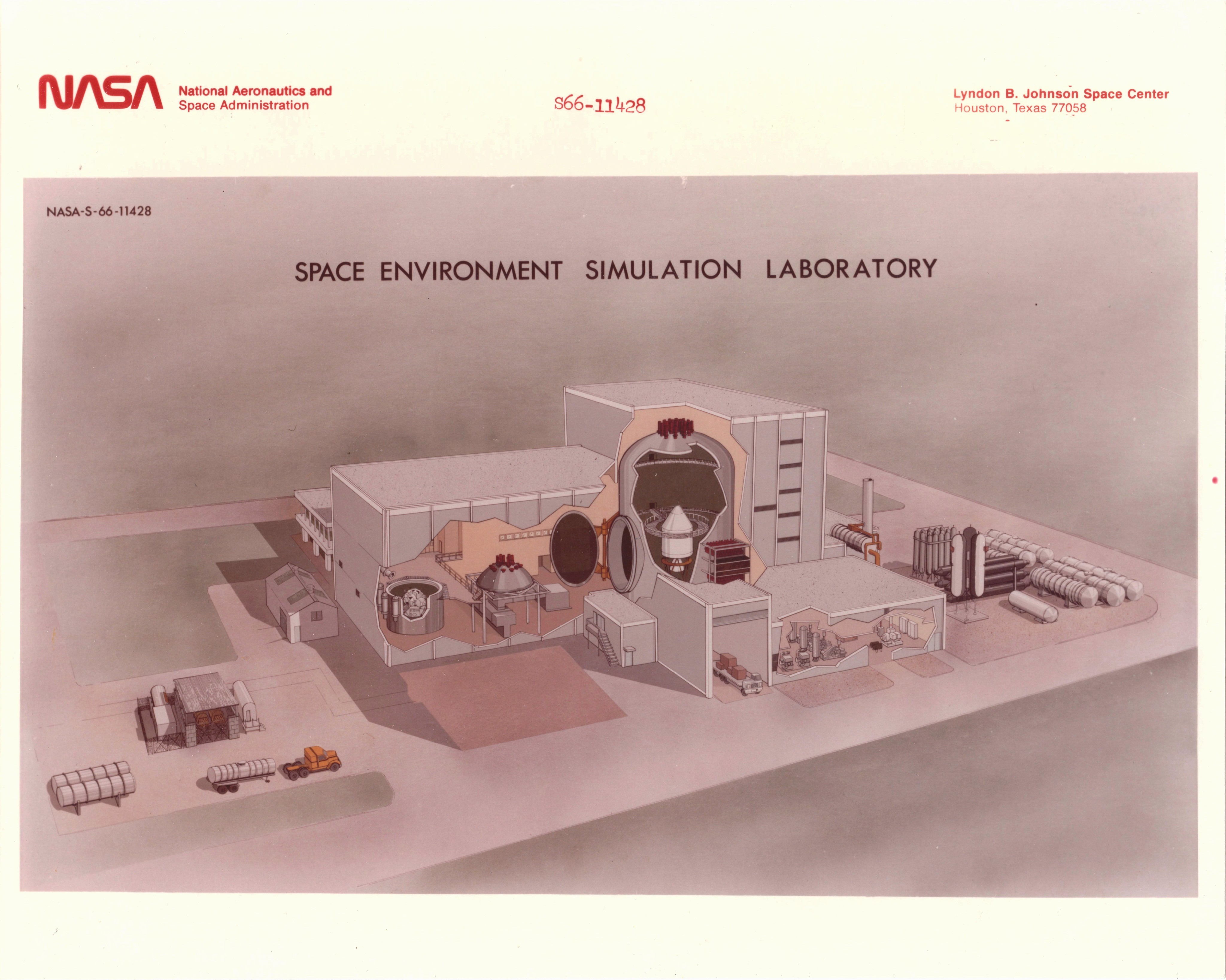
“The SESL was built in 1965 to conduct thermal-vacuum testing for all US manned spacecraft of the Apollo Era. The large size of chamber A meant that full-scale flight hardware could be tested. In addition to Apollo modules, it has been used to test spacesuits, the Skylab/Apollo telescope mount system, various Space Shuttle systems, the Apollo/Soyuz docking module, and various large-scale satellite systems.
The Space Environment Simulation Lab (SESL) contains two large man-rated chambers, instrumentation and data systems, and support facilities. The test chambers have been designated a National Historic Landmark. The chambers, used for space simulation tests, have rotatable floors, dual man-locks to move from ambient air pressure to a thermal-vacuum environment, and irradiation capabilities for various solar simulations.
The Space Environment Simulation Laboratory (SESL) was primarily used to test every command, service, and lunar module sent to space to determine how they would react to the space environment. The chambers were depressurized and cooled to determine how hardware would behave in space. For example, would the modules leak fluids? Would the modules be able to operate in the cold conditions? Would the properties of certain coatings, such as the thermal shield, change when the environmental conditions changed? Astronauts also used the chambers to practice using the modules in such extreme conditions, further readying the astronauts for space travel.”
The above, with some interesting photographs, at:
crgis.ndc.nasa.gov/historic/Space_Environment_Simulation_Lab
Credit: NASA Cultural Resources (CRGIS) website
Also:
www.de-la-terre-a-la-lune.com/apollo.php?page=technos_msc...
Specifically:
www.de-la-terre-a-la-lune.com/vehicules-et-technologies/m...
Both above credit the excellent “De la Terre à la Lune” website
en.wikipedia.org/wiki/Space_Environment_Simulation_Labora...
Credit: Wikipedia
More recently:
pdfs.semanticscholar.org/21db/7fdac7d49acdb7c45018b772c35...
A National Historic Landmark since 1985…rightfully so.
PictionID:53809508 - Catalog:14_031019 - Title:Apollo Details: Apollo Mission Model Date: 05/09/1961 - Filename:14_031019.tif - - Images from the Convair/General Dynamics Astronautics Atlas Negative Collection. The processing, cataloging and digitization of these images has been made possible by a generous National Historical Publications and Records grant from the National Archives and Records Administration---Please Tag these images so that the information can be permanently stored with the digital file.---Repository: San Diego Air and Space Museum
Apollo 6 Command Module landed in the Pacific, northwest of the Hawaiian Islands at 4?46 PM, EST, April 4, 1968. Apollo 6 was the second unmanned flight of the Saturn V in the National Aeronautics and Space Administration’s Lunar Landing Project.
Launch: April 4, 1968 7AM Complex 39 Kennedy Space Center, Fla.
Impact Zone: 27°40’ N - 157°55’ W / 50 Nautical miles West of the scheduled impact area.
Onboard Carrier (USS Okinawa) 15 hrs 55 min GET
"An artist's concept depicting a scene in Earth orbit during the Apollo transposition and docking maneuvers of the Apollo-Soyuz Test Project mission. The Command/Service Module is moving into position to dock with the Docking Module. Following the docking the DM will be extracted from the expended Saturn IVB stage. The Docking Module is designed to link the American Apollo spacecraft with the Soviet Soyuz spacecraft. This scene will take place some one hour and twenty-three minutes after the Apollo-Saturn 1B liftoff from the Kennedy Space Center on July 15, 1975. The Soyuz launch at 7:20 a.m. (CDT) from the Baikonur, Kazakhstan launch pad will precede the Apollo liftoff by seven and one-half hours. The artwork is by Paul Fjeld."
Above at:
spaceflight.nasa.gov/gallery/images/apollo-soyuz/apollo-s...
Mr. Fjeld is one of those individuals that people like me are immensely grateful to, for doing what they do and the way they do it! His contributions to capturing & preserving the history and visual spectacle of space flight are diverse and just plain fantastic. A few examples:
gizmodo.com/13-amazing-paintings-of-space-based-on-actual...
Credit: Gizmodo/Attila Nagy
www.collectspace.com/ubb/Forum9/HTML/002461.html
Credit: collectSPACE website
www.ninfinger.org/karld/My Space Museum/q3.htm
Credit: Ninfinger website
www.hq.nasa.gov/alsj/fjeld.html
Credit: ALSJ website
Wouldn't you agree?
Thank you Mr. Fjeld!
I believe the photo to be authentically signed.
The Command Module (CM) in each image of the montage is the same one. I've circled just one of the features that clearly confirms such, there are plenty of others.
For reference, the photo on the left was taken at Expo ‘67 in Montreal…which is, literally - EVERYWHERE, since DAY ONE - MISIDENTIFIED as CM-011, flown during AS-202.
WRONG, WRONG & WRONG:
www.youtube.com/watch?v=u4ZgVRJ-H8U
Credit: Shane Saldana/YouTube
THIS is NOT supposed to be the rocket science part!
The reentry scars of each CM are like fingerprints, greatly aiding in spacecraft identification. In this instance further simplified by all of these photos having been taken in 1967 or earlier. Not a whole lot of flown CMs as of that time to befuddle even simpletons, or so one would’ve thought.
Somehow, DESPITE that, some nasa stooges managed to f**k it up, ROYALLY. And it's still f**ked up, and likely to remain that way.
PATHETIC, HUMILIATING, STUPID, CARELESS, INCOMPETENT…along with multiple other derogatory adjectives that escape me at the moment.
My several futile attempts to POLITELY, DEFERENTIALLY EVEN, bring this to somebody’s/anybody's attention within n(Ass)a was met with either crickets or the lone "I'll pass it on to [yet another unresponsive n(ASS)a douche bag]."
At least those who saw it, let alone remember it, or even knew/cared about what they were looking at, are pretty much all DEAD - so "no harm/no foul."
Isn’t that right…you TOTAL POS, unnecessarily & UNFOUNDEDLY arrogant & dismissive n(Ass)a History Office/Department/Section/Closet (and other) tools???
To hell with any conscientious & competent effort at accurate/correct historical record keeping.
Even some members of an otherwise decent site drank the Koolaid, perpetuating the egregiously inexcusable, inexplicable & glaring bungle.
Check out the following link. Remember, this was THE venue to showcase your national wares as it were, during the height of the space race & first Cold War. What a grand stage to 'exhibit' the incompetence & stupidity:
Credit: Pchermayeff/YouTube
Upper black & white photo credit Flickr member “dwt_author”, lower black & white photo credit Flickr member “NM Museum of Space History”. On the left is an image I downloaded from…somewhere...I don’t remember where. And the one on the right is from my personal collection.
“Recovery of Apollo Boilerplate BP-23A after successful Pad Abort Test at White Sands Missile Range (WSMR).”
en.wikipedia.org/wiki/Pad_Abort_Test_2
Credit: Wikipedia
Note the “A” suffix. This boilerplate capsule first flew (as BP-23) during the third abort test (A-002) of the Apollo spacecraft. That’s pretty darned cool:
Credit: Wikipedia
In this photo taken by Command Module Pilot John Young, the ascent stage of the Apollo 10 Lunar Module (LM) is seen prior to docking in lunar orbit. Mission Commander Thomas P. Stafford and Lunar Module Pilot Eugene A. Cernan are returning to the Command and Service Module "Charlie Brown" after descending in the LM, known as "Snoopy," to within 14.4 km of the lunar surface. The LM had flown over Landing Site 2 in the Sea of Tranquility, testing the systems and procedures that would be used during the first Apollo lunar landing that would happen two months later during the Apollo 11 mission. The LM descent stage was jettisoned into lunar orbit.
The lunar surface in the background is near, but beyond the eastern limb of the Moon as viewed from Earth (about 120 degrees east longitude). The red/blue diagonal line is the spacecraft window.
Credit: NASA
Photo number: AS10-34-5112
Date: May 22, 1969
“Apollo Command Module Mockup no. 18, as seen at the engineering Design Inspection Display."
Above per a NASA caption of another photo of the mock-up.
An interesting view of the audience/gallery of observers, I assume composed primarily of NASA personnel, watching three television monitors of the activities within the Command Module mockup in the background, at the North American Rockwell (NAR) plant in Downey, CA.
Thanks to Mr. Ed Hengeveld, what’s transpiring here is a stowage review using the mockup, conducted March 15, 1968. Participating were (then) Apollo 8 astronauts McDivitt, Scott & Schweickart, plus their backups Conrad & Gordon. Later in the day, the test was repeated by Apollo 9 astronauts Borman, Collins & Anders. Possibly, their backups, Armstrong, Lovell & Aldrin also participated, Aldrin at the very least.
In the below linked photograph (of Aldrin), what I erroneously thought was a device to display a simulated exterior view out the window, is instead one of three CCTV cameras documenting activities inside the Command Module.
Note also the diagrams below each television monitor, providing the position & field-of-view of its respective television camera. A Service Module mockup is visible in the background to the upper right.
From the day before, March 14:
NASA announced to the public that program officials had decided to use a 60-percent-oxygen and 40-percent-nitrogen atmosphere in the Apollo spacecraft cabin while on the launch pad (and to retain the pure-oxygen environment in space). This technical decision - because of the earlier tragedy with Apollo 204 over a year earlier - was subjected to closer public scrutiny than perhaps any comparable decision in the history of the U.S. space program. The change affected only ground operations and support equipment and did not necessitate any major changes in the spacecraft itself. Exhaustive testing of the redesigned interior of the vehicle since October 1967 had demonstrated that the risk of fire inside the spacecraft had been drastically reduced. Hardware changes inside the cabin, spokesmen said, had minimized possible sources of ignition and materials changes had vastly reduced the danger of fire propagation.
NASA News Release 68-47, "Apollo Spacecraft Cabin Atmosphere," March 14, 1968."
From/at:
1966 North American Aviation (NAA) artist’s concept of the CSM/S-IVB stack either shortly before, or shortly after, Trans-Lunar Injection (TLI). Most likely – I think – by Gary Meyer.
“LONE SPACE COWBOY
LONE ASTRONAUT -- Dick Gordon, Apollo 12 spacecraft command module pilot, maneuvers craft into position for rendezvous and docking with lunar module returning from moon in this drawing by North American Rockwell’s Space Division. Gordon orbits moon alone Tuesday through Thursday in command module while Astronauts Pete Conrad and Alan Bean explore lunar surface. Apollo spacecraft command and service modules for the Apollo 12 mission were produced for NASA by North American Rockwell’s Space Division.”
The caption per the NASA issuance of the photo:
“In this artist concept, Apollo 12 astronaut Richard F. Gordon maneuvers the command module into position for rendezvous and docking with the lunar module returning from the Moon's surface. Astronauts Charles Conrad, Jr., and Alan L. Bean will transfer from the lunar module into the command module for the return trip to Earth, Apollo 12 will be the Nation's second manned lunar landing mission.”
I've always found this image odd, no matter where I've seen it, in that it's always been identified as being Richard Gordon. I understand mission attribution in artist's concepts, and Neil Armstrong for obvious reasons...but specifically, of an individual Astronaut, rarely, especially in the course of performing a nominal, routine, expected, previously conducted task, like maneuvering the CSM. I like it, but I don’t get it...there had to be some other angle to it. I really don't think it was originally intended to be him...that's the face of a generic 1969 ‘action figure’ Astronaut. ;-)
"Artist concept of AAP-2 spent-stage station with AAP-1 Apollo CSM docked at axial port and AAP-1 Mapping & Survey System docked at radial port."
Flickr: Explore!
All of the above, and below link are from David S. F. Portree's fantastic blog. An absolutely amazing source of a plethora - actually whatever is more than 'plethora' - of incredibly informative and exceedingly well written space articles.
spaceflighthistory.blogspot.com/2015/07/before-fire-nasas...
To me, the artist’s signature looks to be “Lois A. Smith”, which is fantastic...a woman artist…of space ‘stuff’ - in 1966!!!
…and, thanks to Legacy.com, a huge WIN!!! Move over Rosemary Dobbins. Yesss:
“November 23, 1926 - August 23, 2020
Lois Virginia Archambeault Smith, 93, of Huntsville, Alabama, passed away Sunday. Lois was born in New York, New York and moved to Huntsville in her late teens. She married Wilfred Warren Smith in Huntsville, had three children, and loved working as one of NASA’s and Werner Von Braun’s original artists from 1958-1978. Upon retiring, she created beautiful oil, pastel, and watercolor art. She traveled to Europe, South America, the Mediterranean and the Far East. Lois loved her family, dogs, cats, cars, gardening, and playing Texas hold-em. She was absolutely adored by family and friends.
Survivors include children, Susan ‘Susie’ S. Brown (Jim), Stephen ‘Bubba’ W. Smith (Jean Ann), and Robin Smith Goldsmith; grandchildren, Kelly V. Givan (Steve), and Jennifer V. Goecke (Paul); great-grandchildren, Paige Givan, Parker Givan, Connor Goecke, and Collins Goecke; and cousins by marriage, Patrick Smith and Mike Smith and their families.
A family only graveside service was held at Maple Hill Cemetery on August 25, 2020 with the Reverend Red Kerusso officiating.
Special appreciation to Brookdale Jones Farm Assisted Living for their superior care and friendship of Lois from 2019-2020.
In lieu of flowers, memorials may be made to the American Heart Association (www2.heart.org).”
The above, with a wonderful photo, at:
www.tributearchive.com/obituaries/18054803/Lois-Virginia-...
And:
www.legacy.com/obituaries/legacy/obituary.aspx?pid=196691199
The following used to be a wonderful & creative ‘display’ of artist’s concepts, as if actually being in a virtual art gallery! No longer. Dumb-asses:
artgallery.msfc.nasa.gov/4636.html
A wonderful rarely published/seen photograph taken by Apollo 9 Lunar Module Pilot (LMP) Rusty Schweickart, during his Extravehicular Activity (EVA). Based on the view/perspective, possibly taken while he was still secured to Lunar Module “Spider’s” porch, using the foot restraint apparatus referred to as the “golden slippers”.
Obviously, the photograph hasn't been properly cared for/stored, but it's retained reasonable gloss & I'm just glad that it survived.
A fascinating & pleasant discovery - to me - is that a portion of Commander Jim McDivitt’s face is visible in the triangular LMP window. By my estimation, the following features/items are present & identifiable in my labeled version of the photo:
1. coiled 16mm Data Acquisition Camera (DAC) electrical/power cable
2. white Communications Carrier Assembly (CCA)/“Snoopy Cap” microphone boom base
3. helmet neck ring
4. helmet attaching neck ring
5. possible sun reflection along the surface of McDivitt’s bubble helmet
6. NASA Meatball/Vector patch on his A7L pressure suit
7. McDivitt’s partially opened mouth (teeth & lips visible)
The green outlines are of the double reflection of the LM RCS thruster’s nozzle.
Linked to below, in order:
- my labeled version of the image
- the same image, from the “Project Apollo Archive”
- a similar image, however, without McDivitt at the window & more clearly showing the double reflection of the LM RCS thruster nozzle, also from the “Project Apollo Archive”
- a cropped & edited high resolution version of the image taken from the “March To The Moon” website
The rest of the window’s surface reflects the clouds (and possibly water) of the earth below. The conical Kapton-covered surface of the docked Command Module, with its protruding umbilical fairing, are visible to the upper left. Finally, the large circular feature to the far right is the flashing tracking light, which apparently was inoperative during the flight. The smaller circular feature to its left is the white docking light, the colors of the other three docking lights being yellow, red & green. Who knew?!
I wonder if this photo is in Andy Saunders' book, "APOLLO REMASTERED", which looks to be fantastic. I'd better pick up a copy.
Last, but NOT least. THANK YOU MR. ARMSTRONG:
www.collectspace.com/news/news-020915a-neil-armstrong-art...
Sort of similar stuff going on, with great discussion & information:
www.collectspace.com/ubb/Forum29/HTML/001958.html
Both above credit: collectSPACE website
Diagram of U.S. Manned Spacecraft comparison.
Is that an engine exhaust nozzle at the end of the Gemini equipment module? Hmmm.
“At about 10,000 feet, parachutes deploy to bring the spacecraft safely to a ground landing.
Landing occurs in a pre-designated area, the spacecraft’s descent being tracked by radar and optical instruments.”
#Apollo 16 command module at the U.S. Space & Rocket Center, Huntsville AL
22.08.2018 11:06 CDT
24mm 1/100 sec f/8.0 ISO 800
“APOLLO MODEL -- One-twentieth size engineering model of the Apollo Block-I Spacecraft 012, mounted on a spacecraft LEM adapter (SLA). The Lunar Excursion Module, which will be utilized for future Block-II flights, is mounted in the SLA. The Launch Escape System is mounted atop the command module.”
On January 27, 1967, Astronauts Virgil I. “Gus” Grissom, Edward H. White II, and Roger B. Chaffee tragically lost their lives in spacecraft/CM-012.
www.astronautix.com/graphics/1/10074663.jpg
Credit: Astronautix website
PictionID:53765398 - Catalog:14_032224 - Title:Apollo Program Details: Apollo Mock Up; Interior View Date: 10/03/1961 - Filename:14_032224.tif - Images from the Convair/General Dynamics Astronautics Atlas Negative Collection. The processing, cataloging and digitization of these images has been made possible by a generous National Historical Publications and Records grant from the National Archives and Records Administration---Please Tag these images so that the information can be permanently stored with the digital file.---Repository: San Diego Air and Space Museum
The Apollo 11 command module Columbia hatch exterior, as seen during the exhibition, Destination Moon: The Apollo 11 Mission, at The Museum of Flight, Seattle. The hatch served as the entry and exit point to the command module Columbia on the launch pad and after landing.
“Pulling away from Earth, the United States’ Apollo astronauts coast silently through cislunar space, on their way to the historic first manned landing on the pristine surface of the moon. Assisting in the final seven minutes of the Apollo Lunar Module descent is a landing radar system designed and built by Ryan Aeronautical Company.”
Based on Mr. Watts' signature, the photo is oriented in kind.
“Spacecraft Apollo and Pegasus configuration is being mated to the Saturn 10 booster at Complex 37. Atop the launch vehicle is the Apollo spacecraft: boilerplate command and service modules plus the launch escape system tower. The Pegasus spacecraft will be folded inside the specially-adapted service module. After injection into orbit, the command and service modules will be jettisoned and the Pegasus C satellite will be free to deploy it panels. The two Apollo modules will enter a similar but separate orbit.”
Note the lack of RCS thrusters, save possibly one dummy, since the service module ‘shell’ was jettisoned shortly after achieving orbit, in order to deploy the Pegasus micrometeoroid detection satellite.
PictionID:53813449 - Catalog:14_031288 - Title:GD/Astronautics Models Details: Apollo Mission Model; with Flaps Open Date: 05/14/1961 - Filename:14_031288.tif - - Images from the Convair/General Dynamics Astronautics Atlas Negative Collection. The processing, cataloging and digitization of these images has been made possible by a generous National Historical Publications and Records grant from the National Archives and Records Administration---Please Tag these images so that the information can be permanently stored with the digital file.---Repository: San Diego Air and Space Museum
A final futile rant into the abyss, for my own edification & catharsis, since my recent posting of the CM-009 recovery photo rekindled my infuriation & disappointment.
Since 1967, NASA - and quite literally – EVERYONE has identified/propagated the Command Module that was on display at Expo ’67 as being CM-011, flown during the AS-202 mission.
With this post, I CANNOT any more simply & conclusively, comparatively demonstrate that this is WRONG.
It's been wrong for FIFTY-EIGHT (58) years, and counting!
Upon even only a cursory look at my montage, it should be/have been OBVIOUS that it was CM-009, flown during the AS-201 mission.
Yes, the “UNITED STATES” & U.S. flag in the red-bordered image of CM-011 corresponds to those on CM-009.
HOW HAS THIS BLUNDER BEEN PERPETUATED FOR THIS LONG?
INEXPLICABLE.
MIND BLOWING.
AND, TO ME, INEXCUSABLE.
As a slightly surreal & mildly sad example of the contagious collaborative cluelessness, read the following:
share.google/lBTKJArlWmpfUQE0S
Credit: “NASA Spaceflight” website/forum
↑ ↑ ↑ ↑ ↑ ↑ ↑ ↑ ↑ ↑ ↑ ↑ ↑ ↑ ↑ ↑ ↑ ↑ ↑ ↑ ↑ ↑
Huh??? Potent, heavily-laced Koolaid indeed. Also consider the bloke’s consequently misinformed dad.
It’s like I’m in a rejected episode of the “Twilight Zone”, as I seem to be the only one that’s caught this, and frankly, the only one that evidently cares…with several NASA individuals having both dismissed and ignored me several years ago when I earnestly, naively & foolishly attempted to bring it to their attention.
With that said, although well written...
share.google/Zd3CKpemSwswVqGXK
share.google/6a6Cg7oyIY1gHRCCJ
Doesn’t an accurate historical/pictorial record matter, even if it’s now a moot point?
Buffoonery...on the world stage, with the first space race & Cold War raging.
And, for crying out loud, it was Apollo/Saturn.
Finally…potentially disconcerting is the fact that both CM-009 & CM-011 were subsequently used in land drop-tests. Were they correctly identified then? ¯\_(ツ)_/¯
And extrapolating further, are the two capsules correctly identified at their respective display venues?
Images used in the montage are from my personal collection, the DVIDS website, Ed Hengeveld's post to the "Space Hipsters" FB group, at: www.facebook.com/photo.php?fbid=7223350381062132&set=...
...the Internet Archive website, and a photo "pay-to-play" site that’ll remain nameless.
Edwin E. “Buzz” Aldrin, Jr., is seen sitting in the hatchless opening of what appears to be an Apollo Command Module simulator at – I suppose – North American Aviation’s Downey CA. manufacturing plant, March 15, 1968. The cylindrical, can-like object affixed to the side window may be a projector, to provide simulated views out the side window?
Note the bin in the foreground with a camera (possibly an Intravehicular variety Hasselblad), along with another camera and/or lense(s)?) Possibly to be used for photography training...of simulated views outside the side window?
As of the date of the photograph, Aldrin, Collins & Armstrong had not yet been named as the crew of Apollo 11, which consensus of those in the know has determined, was January 9, 1969.
www.facebook.com/share/p/1Bre7nDMmQ/?
Credit: Stephen Isherwood/“APOLLO SPACECRAFT HISTORY” FB group
I don’t know. Obviously, it’s a Command/Service Module configuration of some sort. I don’t even think the Command Module (CM) is a boilerplate. Does it qualify as a mockup? An engineering model? Although externally, it’s relatively featureless, at least from this perspective, there does appear to be instrumentation internal to it. And note that the orifice on the right of it appears to have a hinged access door.
Lastly, the technician at left is wearing a lab coat bearing “NASA TECHNICAL SERVICES” on the back, so I think it’s at least safe to assume this is at a NASA facility, MSC I’d think.
Could it possibly be what’s in the photo I’ve linked to below?
Regardless, it’s cool.
Brings to mind Starhip.
“APOLLO 2TV-1 ACTIVITY – View of the Apollo spacecraft 2TV-1 inside Chamber A, Space Environment Simulation Laboratory, Manned Spacecraft Center, prior to manned thermal-vacuum testing.”
commons.m.wikimedia.org/wiki/File:Space_Environment_Simul...(Harris_County,_Texas).jpg
upload.wikimedia.org/wikipedia/commons/d/de/Space_Environ...
.jpg)
Credit: Wikimedia Commons website
en.wikipedia.org/wiki/Space_Environment_Simulation_Labora...
Credit: Wikipedia website
"TERMINAL DESCENT"
What I'm assuming to be the three pilot parachutes, fully deployed. However, they appear to be extending from a common trunk, which is attached to what appears to be the main parachutes' housing canister? Which is pulled off by the pilot chutes? Nah, that’s not right.
They can't be the main parachutes, can they? Not at that size & proximity to the capsule.
Not that it would necessarily be reflected in this depiction, but this might still have been during/a part of the Earth Landing System (ELS) consideration. Regardless, something isn't quite right.
I think "TERMINAL", along with “VELOCITY”, would indeed be the operative word for this configuration.