View allAll Photos Tagged Configuration
"Building got us no where. Time to adapt to changing times and changing accessories..."
______________________________________________________________________________________________________________
More lego movie stuff, yay~ Woohoo~...seriously, let me know if I'm over playing this. Cuz it kinda feels like it. I made this scene out of mostly parts you can find Cycle chase set as well as a few random odds and ends.
I can't really call this Apocbarf because I didn't just throw these two together (well, Emmet I kind of did). Anyways I really like how they turned out and I hope I will inspire some people to do more LM related alternate fig configurations.
the last original....
Bus No: A-309
Year released: 2008
Capacity: 49; 2x2 seating configuration
Route: Cubao/Pasay-San Carlos via Dau/SCTEX-Concepcion/Capas/San Miguel/Tarlac/Sta. Ignacia/Camiling/Bayambang/Malasiqui
Body: Higer Bus Co. Ltd.
Model: 2008 Higer KLQ6119 AC Series
Engine: Yuchai
Fare: Airconditioned
Transmission System: M/T
Plate No.: TXP-114(NCR- National Capital Region)
Taken on: June 22, 2013
Location: Romulo Highway, Brgy. Malacampa, Camiling, Tarlac
Note: Any individual or representative of this subjected bus who wants to use this picture for commercial or personal purposes, pls coordinate me by sending a private message in my FB Account:
www.facebook.com/leonidas.smith.984?ref=tn_tnmn
Thank you and have a good day.....
Model of a mining excavator in front shovel configuration in scale 1:28.5. This 300 tonne machine is a representative of Liebherr's most popular size class and is ideally suited to load a fleet of 100 tonne payload mining trucks.
When LEGO introduced its 42100 Liebherr R 9800, I knew I had to get that set immediately after release. But I also knew from the beginning, that I would not like the official model's Technic design and that I had to build my own version.
Here it is, scaled larger than 42100, but on the other hand representing a much smaller machine than the 9800. About 300 vs. 800 tonnes in real life. This allowed me to use the main components of the official LEGO model to build my R 994 B. I used the clamshell bucket, the Power Functions XL actuators and the tracks and sprockets.
The main difference from 42100 lies in the electric components of my model. The following functions are all powered by two Power Functions rechargeable battery boxes and controlled by three SBricks via bluetooth connection and Brick Controller 2 app:
- Left and right crawler treads each using a Power Functions L motor
- Slewing of the upper structure using two Power Functions M motors
- Boom cylinders: one Power Functions XL motor
- Stick cylinders: one Power Functions L motor
- Bucket cylinders: one Power Functions M motor
- Clamshell bucket: one Brick Engine V1 motor (compatible to Power Functions)
- Access ladder: one Power Functions M motor
- Service flap: one Power Functions M motor
- Lighting: three pairs of Power Functions LEDs
Besides the main drive and digging functions, the model features a retractable access ladder and a lowerable service flap on the underside of the upper structure frame. The service flap is used to refuel and grease the excavator.
While building the Liebherr R 994 B Litronic in 1:28.5 scale, I could refer to a highly detailed diecast model of the very same machine in 1:50 scale.
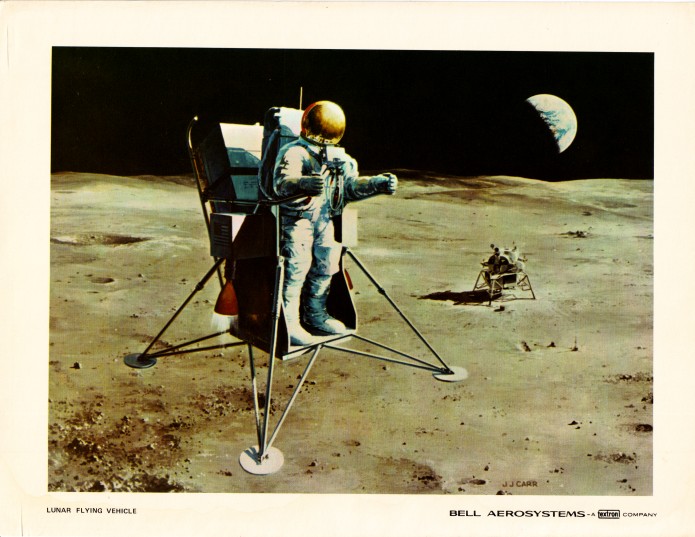
“This artist’s concept depicts one configuration currently being studied by Textron’s Bell Aerosystems Company in conjunction with its one-man Lunar Flying Vehicle preliminary design work for the National Aeronautics and Space Administration’s Manned Spacecraft Center, Houston, Texas. Powered by twin rocket engines, it would be capable of 10-15 mile minimum flight ranges. It also could perform at least 30 sorties and be able to use the residual propellants from the descent stage of the Lunar Module. Mounted to the back of this design is a payload pallet. Motorcycle-like handle grips would be used for thrust and attitude control.”
To my knowledge, the Descent Propulsion System fuel of the Lunar Module was hypergolic. Wouldn’t that’ve been a risky proposition to use?
Note the deployed EASEP/ALSEP components.
Beautiful & iconic (in my world) ca. 1968/69 artwork by Bell Aerosystems’ immensely talented artist, John J. Carr.
See also...always informative & entertaining:
www.aerospaceprojectsreview.com/blog/?s=Bell+Aerosystems&...
Specifically:
www.aerospaceprojectsreview.com/blog/wp-content/uploads/2...
Both above credit: Aerospace Projects Review website/blog
Additional interesting designs:
www.astronautix.com/l/lunarflyers.html
Credit: Astronautix website
INSTRUCTIONS AVAILABLE FOR P558 SUPERDUTY - MULTIPLE CONFIGURATIONS
On September 24, 2015, Ford unveiled the 2017 Ford Super Duty line at the 2015 State Fair of Texas. he frame is made from 95% high strength steel and the body (like the contemporary F-150) is made from 6000 series aluminum alloy. For the first time since 1999, both the Super Duty and F-150 lines are constructed using the same cab.
For 2017 production, the Super Duty line shares its powertrain lineup with its 2016 predecessor: a 6.2L gasoline V8, 6.8L V10 (F-450 and above), with a 6.7L diesel V8 available in all versions. The 6.2L gasoline V8 engine remains at 385 hp but torque rises from 405 lb-ft to 430 lb-ft. Additionally, the gasoline V8 produces its max torque at over 700 rpm less than the previous 405 lb-ft engine. The 6.7L diesel engine also remains at the same 440 hp (323 kW) but torque increases from 860 lb-ft upwards to 925 lb-ft.
The 2020 Super Duty debuted at the 2019 Chicago Auto Show. It features a revised grille and tailgate design, new wheel options, and higher-quality interior materials for the Limited trim. A new 7.3-liter gasoline engine is available. Nicknamed "Godzilla", it makes 430 horsepower and 475 lb-ft of torque.
Cab configurations continue to be 2-Door Regular Cab, 4-Door Super Cab, and 4-Door Super Crew Cab, with Short Box (6' 9") and Long Box (8') bed lengths. The truck will be available in F-250, F-350, and F-450 pickup truck models, and F-350, F-450, and F-550 chassis cab models. All will be available in both 4X2 and 4X4 configurations. The F-350 will be the only model available in either Single Rear Wheel (SRW) or Dual Rear Wheel (DRW) configurations, the F-450 and F-550 will only be available in a Dual Rear Wheel (DRW) configuration, and the F-250 will only be available in a Single Rear Wheel configuration.
I have received quite a few e-mails asking for info on my Digiscoping set-up.
So here we are.
The GI comes with a Kit lens as standard and can be used with Kowas 25x eyepiece(No vignetting) and also with the 30x eyepiece(some vignetting).NOTE :Using this method you can Digiscope in auto-focus with the G1.
However the image you see here shows the G1 kit lens removed and a 4/3 t-adapter inserted into the GI.
Kowas Photo-Adapter ref:TSN-PZ 680mm-1000mm(Expensive,around 650 euros) is attached to the t-adapter and the TSN screws directly into the scope.
Now,with this configuration you can only shoot in manual focus,using the scopes focusing.
This mehod has advantages and disadvantages.
1.Manual focus method.Greater focal length is achieved but !!! IF YOUR FOCUS ON THE SUBJECT IS NOT PERFECT,YOU MAY AS WELL BIN THE IMAGE.NO PRISONERS TAKEN.NOT FOR EVERYBODY THIS METHOD.
2.Kit Lens configuration.Great for fast moving subjects such as waders but !!!!,if you move around a lot searching for your subjects (I do) the Kit-lens can move away from the eyepiece a fraction and you have to start fiddling around to set everything up again.NOT IDEAL.Yet if you are static,no problems.
I have tried both methods and i now shoot 100% in Manual.But again,a question of choice.
One more thing to say re: above image:BE AWARE?THIS SYSTEM IS VERY HEAVY !!!!.SO TAKE PLENTY OF VITAMIN PILLS BEFORE STARTING OUT FOR A DAY !!!!!! lol.No,to be serious for a moment.It is heavy for a reason :Strength and Stability.Essential for Digiscoping success.
The Kowa Scope and GI are attached to Kowa's DA10 universal Mounting System(Around 350 euros) and then to a Top-Range Manfrotto Tripod (Again around 350 euros).Get the best tripod you can afford.YOU MUST HAVE COMPLETE STABILITY AND STRENGTH IN THE TRIPOD.
THE DA10 IS ESSENTIAL FOR DIGISCOPING SUCCESS WHY ?
Stability(I keep using this word,in other words NO MOVEMENT WHEN TAKING THE IMAGE) is so important in digiscoping and i have found that even in very high wind conditions using the DA10 gives me incredible stability and everything is locked down "Tight".No movement at all.It must be said that using the kit lens configuration there is not the same degree of stabiliy,because there are 2 elements (Lens and Eyepiece) that can move slightly.I just sling the gear over my shoulder and move on,spot a subject AND BE READY TO SHOOT INTANTLY.
I have so much confidence in the stability that i shoot all the time using my finger and NOT a cable release.Just one final point as to why i use the G1.I started digiscoping using the Nikon coolpix P6000 a wonderful camera for Digiscoping BUT it had to be used with a Hoodman Loupe so that in bright sunlight you could see what you were trying to shoot !!!!.I found the system cumbersome with elastic bands wound around the scope A real messy operation and there is no possibility of "Rapid Fire" shooting as you have with the G1. With the P6000 only one shot could be taken at one time.
Finally.
This system works for me but as i said earlier it's not for everyone.Unfortunately,to digiscope successfully is not cheap.DO NOT UNDER ANY CIRCUMSTANCES BUY A CHEAP SCOPE OR CAMERA.YOU WILL BE DISSAPPOINTED IN THE RESULTS.This set-Up will cost you around 4200 euros.God !!!!! i've just had a heart attack !!!! lol.
If you would like to see images from "Master" Digiscopers using Kowa Scopes check out my flickr friends photostreams.They are all using different cameras and different methods but their images are amazing.
1.Kevin Bolton.
2.Paul Hackett.(Thanks Paul for all your invaluable help when i began,you started me off "On the Right Track".
3.h2otara(Tara Tanaka) Kowa/GI.(Tara helped me enormously when i began 2 years ago)
4.Roy Halpin.
I hope this post will help people who are interested in Digiscoping.For me it is form of bird photography with tremendous challenges and is immensely rewarding.
Best wishes from North West France.
A pair of VF-1SPs in clean configuration, soaring among the clouds like albatross seabirds.
History:
The VF-1SP was a series of early VF-1A Block 2 Valkyries, modified for long range naval patrol, reconnaissance and manned guidance platform for land-started cruise missiles against large sea, ground and aerial targets during mid and final flight stage.
Taking the basic single seater hull, the VF-1SP received a much larger wingspan with extra weapon hardpoints (the inner pair most often dedicated to a pair of 500 gal. drop tanks) and additional internal fuel capacity. While agility and top speed was reduced, the new glide wing allowed a much longer loiter time on duty.
For the intended patrol and reconnaissance role, the sensor equipment was enhanced, too. This included an IR tracking system, a laser painter for guided precision weapons and a comlink for long range missile guidance.
The first SP ("Special Performance") Valkyrie prototype was built and flown in 2011, and after trails and approval a total of 50 serial machines followed in 2012 and 2013. The whole series was based on the Japanese homeland with SVF-52 and SVF-53, on Hokkaido and Okinawa, respectively.
The idea:
Inspired by my recent "Viggen"-Valkyrie in "Fields & Meadows" camouflage I found enough drive to work on another lookalike-Valykrie: emulating the not-so-well-known Mitsubishi F-2. The Japanese F-2 fighter is, more or less, a converted General Dynamics F-16 with larger wings, optimized for defense of the Japanese coast against sea attacks, and for close air support. The F-2 is also used for interception tasks as secondary role, and it is primarily replacing the F-1 and F-4EJ. Beyond looking quite elegant and being Japanese, the typical camouflage pattern of these machines (also found on late F-4EJ Phantom II's) is very appealing, too: medium blue overall with dark blue contrast fields from above, a light grey radome and bright red Hinomaru markings. These machines are VERY attractive - reason enough to dedicate a Valkyrie to these beauties ;)
Assembly:
The kit is, as usual, a vintage 1:100 scale VF-1 Valkyrie Fighter kit from ARII, in this case even a bash of two kits due to various modifications. Usual added details include a HUD, a pilot figure, seat belts and an ejection seat trigger in the cockpit. Externally, some typical Valkyrie antennae on the outside were added.
But this time, things went further: The whole airframe was enlarged, much like the F-2 compared to the original F-16! Each wing was elongated by ~1/2", with parts from another Valkyrie's wings, holding a third, outer weapon hardpoint now, too. In the intersection area between cockpit and main body, the fuselage was elongated by about 4mm in order to compensate for the considerably larger wing span, balancing proportions.
Another trick to stretch the Valkyrie was a thorough modification of its vertical fins: These parts received a leading edge extension at the root, additional 3mm in height and a rear extension which mimics the F-2's fin shape with its bulbous parachute container. Furthermore, the fins were placed about 4mm further back, shifting the visual "center of gravity" backwards. Additional F-2 features are several typical radar sensor bulbs all over the fuselage, and the small antennae (or spoilers?) in front of the cockpit.
With so many changes (and a VF-1D head under the hull), I deemed a new designation to be appropriate: the VF-1SP, reminiscent of the Boeing 747 SP ("Special Performance"), a heavily modified, long range version of the Jumbo Jet ;)
The underwing weapons are a mix from various sources. The two pairs of slender laser-guided bombs under the innermost pylons come from a Hasegawa weapon set (actually, these are Japanese weapons with an IR head and even authentic for an F-2!), the racks are scratch-built. The grey missiles are 1:72 AIM-4F Falcon, but at 1:100 scale they look like neat air-to-ground missiles like AGM-65 Mavericks. The outermost hardpoints finally hold standard AMM-1 missiles for self-defence - I just added two on each side, to create an asymmetrical look and to avoid a cramped impression.
Paint & decals:
The paint scheme is rather simple, and you find lots of very good reference pictures of the F-2. But finding a good match for the blue tones is another thing! I found some color reference in painting instructions (e .g. from Hasegawa), but I am not sold on the recommended tones at all. According to these sources, the "real" colors are FS35164 (Intermediate Blue) and FS15042 (Sea Blue) - actually two tones which were used on US Navy planes in WWII? Depending on light, film material and processing, F-2 pics offer no hard evidence, though: the tones appear in a very wide range from bright sky blue to a murky and dull blue-gray for the lighter blue, and the dark blue cannot be defined at all, it is just "very dark blue".
Since impression counts, I went for something brighter and settled on Humbrol 109 (WWI Blue, a very deep tone) for the lighter blue and Humbrol 104 (Oxford Blue, very dark and with a violet hue) for the dark tone. The radome was finished in Humbrol 28 (Camouflage Grey, FS36622, probably the authentic color), and the wings'/fins' leading edges were painted in grey (Humbrol 140) for some extra contrast. This color can also be found at some other details
Concerning markings, I tried to stick to the F-2 paradigm but could not resist to add some squadron markings on the fins: what looks like abstract kanji on the fins' outer sides are highly stylized "53"s - symbols of Japanese WWII 53rd Sentai. They come from an AeroMaster aftermarket decal sheet for Ki-45 Toryu fighters - and in red, they fit perfectly, and we have a plausible SVF-53 squadron ;)
After basic painting, the kit received a light wash with black ink and some fine liner treatment. Then, decals and finally a coat of matte varnish was appllied.
In the end I think the decision for the brighter colors paid out - we are doing anime here, after all, so something bright is IMHO not wrong at all! Looks pretty, methinks?
+++ DISCLAIMER +++
Nothing you see here is real, even though the conversion or the presented background story might be based on historical facts. BEWARE!
The Supermarine Spitfire was a British single-seat fighter aircraft used by the Royal Air Force and other Allied countries before, during and after World War II. Many variants of the Spitfire were built, using several wing configurations, and it was produced in greater numbers than any other British aircraft. It was also the only British fighter produced continuously throughout the war.
The Spitfire was designed as a short-range, high-performance interceptor aircraft by R. J. Mitchell, chief designer at Supermarine Aviation Works, which operated as a subsidiary of Vickers-Armstrong from 1928. Mitchell pushed the Spitfire's distinctive elliptical wing designed by Beverley Shenstone to have the thinnest possible cross-section, helping give the aircraft a higher top speed than several contemporary fighters, including the Hawker Hurricane. Mitchell continued to refine the design until his death in 1937, whereupon his colleague Joseph Smith took over as chief designer, overseeing the Spitfire's development through its multitude of variants and many sub-variants. These covered the Spitfire in development from the Merlin to Griffon water-cooled inline engines, the high-speed photo-reconnaissance variants and the different wing configurations.
One exception was the Spitfire Mk. X: it was the only variant powered by a radial engine, and it looked quite different from its sleek Merlin-powered brethren. Early in its development, the Merlin engine's lack of fuel injection meant that Spitfires and Hurricanes, unlike the Bf 109E, were unable to simply nose down into a steep dive. This meant a Luftwaffe fighter could simply "bunt" into a high-power dive to escape an attack, leaving the Spitfire behind, as its fuel was forced out of the carburetor by negative "g". An alternative engine was to solve this issue. Another factor that suggested an air-cooled engine were theatres of operations in the Far East, primarily India: the hot and humid climate was expected to be a severe operational problem for the liquid-cooled Merlin. As a further side effect a radial engine was expected to be easier to maintain under these conditions than the Merlin.
The project of a radial-powered Spitfire variant was eventually launched in late 1940. The choice for the power unit fell on a Bristol Taurus II 14-Cylinder engine, which had an appreciable small diameter, was available in ample numbers and had about the same power output as the early Merlin variants used in the Spitfire Mk. I and II (1.030 hp/740kW). In order to save time and keep the radial engine variant as close as possible to the Spitfire V design, the production type of that era. The new type’s structure and fuselage were only adapted to a minimum to allow the bulkier power unit and its periphery to be taken. The fuselage was widened in front of the cockpit section, a new engine mount was integrated and the Merlin’s radiator bath and respective piping were removed. The oil cooler under the port wing was retained, though, and the Taurus engine was from the start outfitted with dust filters, so that all resulting Spitfire Mk. Xs left the factory tropicalized. Like the Spitfire Mk. V, different wing armaments were available, e.g. an “A” wing with eight .303 in machine guns and a “B” wing with two 20 mm cannon and four machine guns.
The first Spitfire Mk. Xs, finally outfitted with a more powerful Taurus VI engine, were delivered to homeland RAF units for evaluation from May 1941 onwards. From the start, the radial-powered Spitfire proved to be inferior to the Merlin-powered variants - even to the early Mk. Is – and they were no match to the modern German fighters, especially at high altitude. As a consequence many Mk. Xs received clipped wing tips for better roll characteristics at low altitude (receiving an additional “L.F.” designation), but this did not significantly improve the type’s overall mediocre performance. Only a few Mk. Xs were actually employed by front line units, most were quickly relegated to training units. Later production aircraft were immediately shipped to the Far East or to units in Northern Africa, where they could be used more effectively.
A few machines were also delivered to Egypt (30), the Netherlands (12 for the East Indies NL-KNIL, which eventually ended up in RAAF service) and Turkey (24). In 1942, many machines still based in Great Britain were handed over to the USAAF, being either used for USAAF pilot and conversion training, or they were allocated to the Northern Africa invasion force during Operation Torch.
Since the Taurus-powered Spitfire turned out to be quite ineffective (it was no good either in the fighter or in an alternative ground attack role and 20 mph slower than the comparable Mk. V), production was already stopped in late 1942 after 353 aircraft. At the same time, the Spitfire Mk. IX with a much more powerful Merlin engine entered service, and all resources were immediately allocated to this more potent fighter variant and the idea of the Spitfire with a radial engine was ultimately dropped. Since the Taurus-powered type was quickly phased out of frontline service, the designation was later re-used for a pressurized high-altitude photo reconnaissance variant of the Spitfire, the PR.X, of which only 16 machines were built.
General characteristics:
Crew: one pilot
Length: 29 ft 6 in (9.00 m)
Wingspan: 32 ft 2 in (9.80 m)
Height: 11 ft 5 in (3.86 m)
Wing area: 242.1 ft2 (22.48 m²)
Airfoil: NACA 2213 (root)
NACA 2209.4 (tip)
Empty weight: 5,065 lb (2,297 kg)
Loaded weight: 6,622 lb (3,000 kg)
Max. takeoff weight: 6,700 lb (3,039 kg)
Powerplant:
1× Bristol Taurus VI 14-Cylinder sleeve valve radial engine, 1.130 hp (830 kW)
Performance:
Maximum speed: 350 mph (312 kn, 565 km/h)
Combat radius: 410 nmi (470 mi/756 km)
Ferry range: 991 nmi (1,135 mi/1,827 km)
Service ceiling: 36,500 ft (11,125 m)
Rate of climb: 2,535 ft/min (12.9 m/s)
Wing loading: 27.35 lb/ft2 (133.5 kg/m²)
Power/mass: 0.22 hp/lb (0.36 kW/kg)
Armament:
2× 20 mm Hispano Mk II with 60 RPG
4× .303 in Browning Mk II machine guns with 350 RPG
The kit and its assembly:
My third contribution to the “RAF Centenary” Group Build at whatifmodelers.com, and the next one in chronological order. This one was spawned by the simple thought of “What would a Spitfire with a radial engine look like…?”. I have seen this stunt done in the form of a Fw190/Spitfire kitbash – nice result, but it did IMHO just not look like a “real” Spitfire with a radial engine, rather like an Fw 190 with elliptical wings. And the fact that I had already successfully transplanted a Centaurus engine onto a P-51 airframe made me feel positive that the stunt could be done!
Consequently, the conversion was pretty straightforward. The basis is a Revell 1:72 Spitfire VB (1996 mold), which was – except for the nose section – taken OOB. A simple, nice kit, even though it comes with some flaws, like a depression at the rear of the wing/fuselage intersection and the general need for PSR – not much, but I expected a better fit for such a relatively young mold?
For the engine, I used a personal replacement favorite, the cowling and the engine block from a Mitsubishi A6M2 “Zero” (Hasegawa). The Nakajima Sakae radial engine has a relatively small diameter, so that it serves well as a dummy for the compact Bristol Taurus engine – a replacement I have already used for a radial-powered Westland Whirlwind. The other benefit of the small diameter is that it is relatively easy to blend the round front end into the oval and very slender fuselage of the early Spitfire airframe. This was realized through massive body sculpting from scratch with 2C putty, widening the area in front of the cockpit and expanding its width to match the cowling – I guess that real life engineers would have followed a similar, simple path.
Since the radial engine would not need a radiator, I simple omitted this piece (cut out from the single piece lower wing half) and faired the respective underwing area over with a piece of styrene sheet and PSR. The asymmetrical oil cooler was retained, though. The propeller is a replacement from the scrap box, with a smaller diameter spinner and more slender blades which better suit the open cowling.
Since the Taurus had its best performance at low altitudes, I used the Revell kit’s OOB option of clipped wing tips – a move that makes the aircraft look much faster, esp. with the new, deeper nose section.
Painting and markings:
I did not want classic RAF markings, but still keep the model well within the Centenary GB confines. The original plan had been a classic Dark Green/Ocean Grey livery, which all Spitfire’s in USAAF service and based in the UK received. But I rather wanted to create a frontline aircraft, operated during Operation Torch in late 1942/early 1943 with American roundels – and the grey/green look would not look plausible on a machine taking part in the North African campaign. In fact, any Spitfire with American roundels I found that was used in North Africa carried the RAF Tropical Scheme in Dark Earth/Middle Stone. And, AFAIK, during Operation 'Torch' all British aircraft received American markings in the hope that the Vichy French, who were anti-British due to them bombing their ships in 1940, would switch to the allied cause. They were supposed to think that the Americans would be invading, not British troops as well. So I eventually switched to the classic Tropical Scheme (using Humbrol 29 and Modelmaster 2052 as basic tones), and it does not look bad at all - even though the yellow trim around the roundels does not stand out as much as on a Grey/Green aircraft.
Typically, the RAF codes were retained, as well as – at least during the early phases of Operation Torch – the RAF fin flash. A little personal twist is the pale blue (Humbrol 23, Duck Egg Blue) underside of the aircraft, instead of the typical Azure Blue. The rationale behind is that the Tropical Scheme was originally designed with Sky undersides, and the blue shades were later modifications after initial field experience.
The red spinner is a typical Northern Africa marking, and found on many 5th FS aircraft.
The interior (cockpit, landing gear wells) was painted with RAF Cockpit Green (Modelmaster), while wheels and struts became light grey.
As a standard procedure, the kit received a light black ink wash and a post shading treatment.
The decals were puzzled together from various sheets and sources, the design benchmark was a real USAAF Spitfire Vb from Operation Torch, though. The code letters were taken from an Xtradecal sheet, the roundels come from a Carpena Spitfire sheet, even though I placed American markings in all six positions – the roundels without yellow trim under the wings were taken from a Hobby Boss F6F sheet.
The serial number comes from the Revell kit’s OOB sheet, because it fits perfectly into the kit’s intended time frame. The nose art comes from a P-38 sheet (PrintScale) – not a typical feature for an RAF Spitfire, but a frequent personal decoration among USAAF machines during Operation Torch (e.g. on P-40s).
The Allied yellow ID markings on the wings’ leading edges, which were typically carried by Operation Torch Spitfires, too, were created with generic yellow decal sheet (TL Modellbau), while the maroon machine gun nozzle covers are part of Revell’s OOB sheet.
Finally, the kit received some soot stains around gun and exhaust nozzles, and was finally sealed with matt acrylic varnish.
A bold experiment, and it turned out well. The Zero’s cowling has the perfect diameter for this transplant, and the scratch-sculpted new front fuselage section blends well with the new engine – the whole thing really looks intentional! I am just not certain if the resulting aircraft still deserves the “Spitfire” designation? Even though only the engine was changed, the aircraft looks really different and has a Ki-43ish aura? I guess that a dark green livery and some hinomaru would also look great and pretty plausible?
Their Royal Elite Class bus with 2x1 seating configuration =)
Pansin ko, di pala two-door to kagaya ng Isarog and VLI..
A light and fast ion frigate.Two different flight configuration, one for cruise and one for combat...
The configuration of 3 different classic signals next to three different tracks remains (for now) making for a reason to shoot this backlit scene of NS 21A at Lenox Tower.
-NS ES44DC #7581, C44-9W #9042 leading power
-NS Train #21A
-NS (ex-Wabash) Brooklyn District, near MP D475
-Lenox Tower
-Along Highway 203, Mitchell, IL
-August 11, 2018
TT1_0764_edited-1
St Martin Palace Plain, Norwich, Norfolk
A small church, but everything is in place, the tower, the aisles, the clerestories. It is worth making a tour of the outside to see this, for the current configuration of the interior makes it seem unfamiliar, as we shall see. The church sits in a tight little graveyard with traffic on three sides, trees bowering high around and above. But on closer inspection the current appearance of St Martin is essentially that of a substantial Victorian restoration, as a result of a partial collapse of tower and chancel, and the heavy hand of Edward Hakewill.
Despite the proximity to the cathedral (the Palace in question is that of the Bishop) the setting was rather unlovely until a couple of decades ago, because the Norwich city gasworks sat immediately to the north of it. At one time, there had been a plan for a railway that would have cut St Martin off from the Cathedral precincts, but this is an area of regeneration, and today you would not know that such a controversy had ever existed.
The courts building is now on the site of the gasworks, and this led to St Martin being used for several years as the home of the Probation service. Internally, a split level steel and glass mezzanine provided working space above and below the floors. It ascends into the space beneath the tower, reaching ground floor level at both the west end and in the chancel. The aisle chapels have been glassed in and form meeting rooms. It is all crisp and airy, fully functional without detracting from the former character of the church too much, for the inner walls are pretty much intact and unscathed. Of course, it is now very different to how George Plunkett found it in 1934.
Much of the glass was destroyed in the Norwich blitz, but some good figures by Heaton, Butler & Bayne survived and are now isolated in clear glass. The later figures of Christ in Majesty flanked by Longinus and the Blessed Virgin appear to be by the William Morris of Westminster workshop, installed in 1952. Bikin Hayward thought them poor, but they stand up well for the period, especially the figure of Mary.
A surviving piece of Victoriana is the solemn inscription How Dreadful is this Place: This is the House of God, and this is the Gate of Heaven above the south doorway, which must have concentrated the mind a bit. A good 18th century ledger stone features a skull and hourglass backed by crossed bones, and Lady Elizabeth Calpthorpe's table memorial of 1578 is a good example of the seemly Anglicanism of the period.
Today the building is in use as the headquarters of the Norwich Historic Churches Trust, a worthy use no doubt but it does rather give the place the feel of a museum. Back in 2005 when I was here last I asked the kind man from the probation service who let me wander around if it was a suitable building for its then-use. He said that it was, and that the setting generally encouraged everybody to take each other seriously, and so when clients came for the first time they knew that this was a place that would give them a future. Perhaps the same applies now that the building is the focus of giving the city's historic churches a future.
+++ DISCLAIMER +++
Nothing you see here is real, even though the conversion or the presented background story might be based on historical facts. BEWARE!
Some background:
The Supermarine Jetfire was a stopgap solution in order to introduce a jet-powered interceptor agains German V-1 missiles that threatened the London region from June 1944 on. At that time, the only aircraft with the low-altitude speed to be effective against it was the Hawker Tempest, but fewer than 30 Tempests were available. They were assigned to No. 150 Wing RAF, and early attempts to intercept and destroy V-1s often failed.
One alternative was the jet-powered Gloster Meteor, which still was development - and in order to get the new engine into service (also as a response to Gloster's engagement for E.1/44 with the single-engine "Ace" fighter) Supermarine responded with the idea to replace the nose-mounted piston engine with a single Whittle W.2 engine: The "Jetfire" was born.
The conversion was rather simple: the Jetfire was actually a Griffon-powered Spitfire XIV with as few changes to the original airframe in order to accept the W.2. The aircraft's forward fuselage was widened to accommodate the bulbous engine with a simple nose intake. The deeper forward part of the fuselage with its round diameter gave the aircraft a pronounced "pod-and-boom" configuration.
Internally, the front wing spar had to be bent into an inverted U-shape to clear the engine and its jet pipe.
The W.2 was mounted slightly angled downwards, and the jet pipe was bifurcated so that it ran along the fuselage flanks above the wings, with an exhaust just behind the wings’ trailing edges. To protect the fuselage, steel heatshield were added to the flanks. Furthermore, the former radiator fairings for the Griffon and the respective plumbing were removed and faired over, saving weight and internal space – and weight was reduced as much as possible to achieve a decent performance with the rather experimental centrifugal jet engine. The conventional Spitfire tailsitter landing gear remained unmodified, just additional covers for the main wheels were added for improved aerodynamics at high speed.
The first prototype was already finished in October 1944, and taxiing trials started immediately. The heatshields proved to be too short and the heat from the engine exhaust melted the duralumin skin of the rear fuselage. Additionally, the tailwheel received a longer strut for a cleaner airflow under the stabilizer on the ground – the original, shorter strut created an air cushion under the stabilizer that lifted the whole tail upwards when the throttle was opened, resulting in poor handling at low taxiing speeds.
Modifications to rectify the problems took until late December, and by this time a second prototype had been completed. After a few taxiing tests, it was transferred to the Royal Aircraft Establishment (RAE) for full-scale wind tunnel testing that lasted until February 1945.
On the 26th of that month, the RAF issued requirements that the aircraft should have a maximum speed of 770 km/h (480 mph) at sea level and a speed of 850 km/h (530 mph) at an altitude of 5,000 meters (16,400 ft). It should be able to climb to that altitude in 4 1/2 minutes or less and it should have a range of 500 kilometers (310 mi) at 90% of maximum speed.
The Jetfire failed to meet these targets, but it was still fast enough to intercept the V-1 and was quickly available. The average speed of V-1s was 550 km/h (340 mph) and their average altitude was 1,000 m (3,300 ft) to 1,200 m (3,900 ft). Fighter aircraft required excellent low altitude performance to intercept them and enough firepower to ensure that they were destroyed in the air rather than crashing to earth and detonating. Most aircraft were too slow to catch a V-1 unless they had a height advantage, allowing them to gain speed by diving on their target.
Originally a total of 200 Jetfire Mk.Is were ordered, and on the drawing board an improved variant with a bubble canopy, a slightly larger tail fin, stabilizers with a 10° dihedral in order to get them better out of the jet efflux’s path and an armament of four 20 mm cannon (the Mk.II) was already taking shape. But this initial and any follow-on orders were quickly cancelled or changed to the more advanced and promising twin-engined Gloster Meteor that finally became operational.
Consequently, the total production run of the Jetfire Mk.I just reached 26 aircraft: 18 were delivered to RAF 616 Squadron, the rest were used by the Tactical Flight at Farnborough that had been established in 1944 in order to prepare active squadrons for the radically new jet fighters. In late March 1945, the Jetfires became operational, upon which both tactical applications and limitations were extensively explored.
Despite many shortcomings (sluggish acceleration, poor climb and agility except for a very good roll rate), the still rather experimental and primitive Jetfire was able to fulfill its intended V-1 interception role, and two V-1 interceptions were achieved during the following weeks. In the front line units they were quickly replaced by more effective types like the Gloster Meteor, the Hawker Tempest or the Republic P-47 Thunderbolt. Anyway, the Jetfire was still helpful to path the RAF’s way for operational jet fighters and helped discover new high speed problems, including compressibility buffeting at higher speeds, causing increased drag, and it showed clearly the limits of traditional fighter aircraft designs.
General characteristics
Crew: 1
Length: 31 ft 8 in (9.66 m)
Wingspan: 36 ft 10 in (11.23 m)
Height: 10 ft 0 in (3.05 m)
Wing area: 242.1 sq ft (22.49 m2)
Airfoil: NACA 2213 (root), NACA 2209.4 (tip)
Empty weight: 8,434 lb (3,826 kg)
Gross weight: 12,211 lb (5,539 kg)
Powerplant:
1× Rolls-Royce B.37 Derwent turbojet, 2,000 lbf (8.9 kN) static thrust
Performance:
Maximum speed: 748 km/h (468 mph)
Range: 395 km (247 miles) with internal fuel only
Service ceiling: 12,750 m (41,820 ft)
Rate of climb: 12 m/s (2362 ft/min)
Thrust/weight: 0.45
Time to altitude: 5.0 min to 30,000 ft (9,145 m)
Armament:
2× 20 mm British Hispano MkV cannons (120 RPG) and
2× 12,7 mm (0.5") machine guns (250 RPG) in the outer wings
Provision for up to six "60lb" 3" rockets under the outer wings,
or two 500 lb (227 kg) bombs, or a pair of drop tanks
The kit and its assembly:
The first entry for the "Old Kit" group build at whatifmodelers.com in late 2016 - anything goes, the kit's mould just has to date back to 1985 and further. For this one I settled on the FROG Spitfire Mk. XIV, which, AFAIK, dates back to 1969, and an engine donor from a KP Yak-23, which is supposed to have hit the markets behind the Iron Curtain in 1981.
Originally, the background story pretty much sums up the idea behind this kitbash: How could the - already fast - Spitfire be further augmented with one of the new jet engines around 1944, when V1 attacks started against the British main land and the Meteor was still in development? A simple engine swap with as much airframe of the piston-engine ancestor would be the answer. Similar ideas had been undertaken in Germany, with re-engined versions of the Bf 109 and the Fw 190, and after WWII, when German jet technology had become available to the Soviet Union, the Yak-15/17/23 family followed a similar pattern.
The Yak-23 came as a natural donation aircraft for the Derwent nose. After careful measures and strategic cuts the Spitfire lost its Griffon engine (already earmarked for another kitbash...) and the Yak-23 its nose and exhaust pipe: the original plan had been to use a central, ventral exhaust pipe under the cockpit, even though this would create issues with the tail wheel (just as on the Yak-15 - it received in service an all-metal tail wheel! Imagine the sparks on the runway...).
Anyway, while dry-fitting the parts it turned out that pretty little of the Yak-23 exhaust section could be mounted with clean lines: I'd either have had to create a semi-recessed exhaust with lots of body work (and pretty implausible), or switch to a totally different solution.
That came with a bifurcated exhaust pipe, running along the wing roots and ending at the wings' trailing edge. While this sounds weird, too, the Hawker SeaHawk actually had such an arrangement - on a service aircraft!
As a side effect, the fairings for the jet pipes now offered a good basis for the necessary intersection between the round and bulky Derwent nose fairing and the narrow, oval Spitfire fuselage.
The new jet pipes were created with styrene tubes and lots of putty, and the result does not look bad at all. Actually, with the deleted radiators and the Griffon carburetor intake gone, the aircraft has a very sleek profile, even though the top view reveals the innate "pod and boom" layout of the nose-mounted centrifugal jet engine.
The latter received a new intake interior with some fine mesh and a central bullet fairing (the Yak-23's vertical splitter would not make any sense, since there'd be no nose wheel anymore). The landing gear was taken more or less OOB, I just added some struts and extra wheel covers. The tail wheel comes from an Airfix Hawker Hurricane and changed into a fully retractable arrangement. The cockpit was taken OOB, too, just a tank dummy was added behind the pilot's seat and the canopy sliced into three pieces for an optional open display.
The "E wing" armament was taken over from the Spitfire Mk. XIV, I just added the elegant drop/slipper tanks from the Yak-23 kit. This breaks up the clean lines of the "Jetfire", but I think that the thirsty Derwent might have needed some extra fuel for a decent approach range and some loiter time while intercepting incoming V-1s?
The V-1 from the FROG kit was built for the flight scenes, too. It’s a very simple model consisting only of four parts with rather mediocre fir, esp. the pulse engine halves, but a fairly good representation. Maybe the propeller for the fuse timer is missing, but that can be scratched easily.
Only personal additions are a grate in the air intake, and a hidden adapter for a display, for the pics. Maybe this flying bomb ends up later as ordnance under a German bomber build?
Painting and markings:
Very conservative, late war RAF Dark Green/Ocean Grey/Medium Sea Grey with typical ID markings and codes. 616 Squadron was chosen because it was one of the units that introduced the Meteor for V-1 interception.
Paints are basically enamels from the ModelMaster Authentic range. The Sky fuselage band was improvised with a decal from a vintage Matchbox Brewster Buffalo (matching the the Sky code letters from Xtradecal pretty well), while the codes and serial numbers themselves were created from single letter digits (the "/G" addition to the serial number signaled that the aircraft was to be guarded at any time while on the ground).
The cockpit interior was painted in very dark grey while the landing gear became aluminum. As a highlight, the air intake edge was painted with silver, more for a dramatic effect than for realism.
The yellow wing leading edge markings were created with generic decal sheet material. The only special markings on the aircraft are the white stripes on tail and wings, which I also used to underlay the serial code.
Only little panel-shading and weathering was done, some panel lines were manually created with a fine pencil since a lot of surface details on the fuselage were lost during the extensive PSR process around the wing/jet pipes area.
Finally, the kit was sealed with matt acrylic varnish.
The V-1 has painted with no special paradigm in mind, with RLM81 upper surfaces and RLM 76 undersides, with a very wavy waterline and some grey patches on the wings. The engine was painted with aluminum first and then a thin coat of red primer added.
The resulting aircraft of this kitbash looks better than expected, even though the change of the exhaust arrangement came unexpected – even though I think the Jetfire became more appealing through the side pipes, despite the overall tadpole proportions.
As a side note, the story is not over yet, because there’s an engine-less Yak-23 left over, and I wonder what it might look like with a piston engine grafted to the empty nose?
Class: Super Deluxe (restroom equipped)
Seating Configuration: 2x1
Body manufacturer: Santa Rosa Phillipines
Body Model: SR Eurobus
Chassis: RB46RS
Engine: Nissan Diesel PE6T
While the landing struts fold up into the body or wings, the wheels, unfortunately, have to be attached and detached. I'll have to come up with something cleaner someday.
Company/Owner: Baliwag Transit, Inc.
Fleet/Bus Number: 1304
Classification: Air-conditioned Provincial Bus
Coachbuilder: Santarosa Motor Works, Inc./Columbian Manufacturing Corporation
Body Model: Santarosa Daewoo Bus BS106
Engine Model: Doosan DE08TIS
Chassis Model: Daewoo BS106 (PL5UM52HDCK)
Transmission: Manual (6-speed forward, 1-speed reverse)
Suspension: Leaf Spring Suspension
Seating Configuration: 3×2
Seating Capacity: 61
Route: Baliuag, Bulacan–Cubao, Quezon City via Old Cagayan Valley Road / N1 (Doña Remedios Trinidad Highway)
Municipalities/cities passing: Pulilan/Plaridel/Guiguinto
Type of Operation: Provincial Operation Public Utility Bus (Regular Class)
Area of Operation: Central Luzon (Region III)
Shot Location: Doña Remedios Trinidad Highway (Maharlika Highway), Barangay Cut-cot, Pulilan, Bulacan
Date Taken: July 20, 2015
Notices:
* Please DON'T GRAB A PHOTO WITHOUT A PERMISSION. If you're going to GRAB IT, please give A CREDIT TO THE OWNER. Also, don't PRINT SCREEN my photos.
** If I have mistakes on the specifications, please comment in a good manner so that I can edit it immediately.
*** The specifications and routes (for provincial, inter-provincial, and city operation) mentioned above are subjected for verification and may be changed without prior notice.
**** The vehicle's registration plate(s), conduction sticker(s), and/or persons (if applicable) were pixelated/blurred to prevent any conflict with the photographer, the bus company and/or to the car owner for their security and/or privacy purposes. So, don't use their plate number, conduction sticker, and vehicle tag as an evidence for any incident. And, I have taken this photo for bus fanatics, bus enthusiasts, and bus lovers purposes.
Built for a LUG challenge build.
My first try with a new configuration of fig; not quite mini and not quite micro.
The iPhone 7 Plus is the first iPhone to have a dual camera imaging configuration. The use of lenses with different focal lengths has greatly expanded the options for different composition without having to fall back on software zooming or cropping in tighter on the subject.
Ztylus and Kamerar have joined forces to produce a lens systems to utilize the dual configuration of the iPhone 7 Plus. Their "Zoom" system (see links below) consists of 2 pairs of lenses that slide over the native lenses. One of these pairs brings a fisheye lens (160 degree field of view, x 0.35 magnification) and a telephoto lens (x 1.5 magnification) to the x1 and x2 native lenses respectively. The other provides a pair of x10 macro lenses for the the x1 and x2 native lenses.
The photograph here was taken using one of the x10 Kamerar/Ztylus macro lenses and the x2 native lense. Although I have only been able to carry out a fairly limited set of trials so far with the macro lenses, I have been quite impressed with the sharpness of the results, as well as the low levels of geometric distortion and vignetting around the edges.
----------
Links for background information ...
kamerar.com/products/kamerar-zoom-lens-kit-for-iphone-7-plus
ztylus.com/products/kamerar-zoom-lens-kit-for-iphone-7-plus
----------
[ Location - Barton, Australian Capital Territory, Australia ]
----------
Photography notes ...
The photograph was taken using the following hardware ...
- iPhone 7 Plus.
- 56mm* (x2) lens [* 35mm equivalent value of the focal length].
- Gizmon TLR Bluetooth Remote Shutter.
- Gray Card made by ProCamera.
I acquired the photograph (4032 x 3024 pixels) with an ISO of 20, exposure time of 1/450 seconds, and an aperture of f/1.8. The iPhone flash was used. A x10 Kamerar/Ztylus macro lens was used in combination with the x2 native lens.
Post-processing ...
- I downloaded the photographs from my iPhone 7 Plus to the MacBook Air 11" using a lightning/USB cable and the iExplorer app (Macroplant).
- Sometimes I do this over WiFi using PhotoSync (touchbyte GmbH). Notably, I have found that iExplorer does not handle properly the images that have been edited using the native Apple iPhone "Photos" app (i.e., it will only transfer the original image, not the edited image).
- I viewed and sorted the photographs that were taken using XnViewMP (Pierre-e-Gougelet) and Lightroom (Adobe Systems Incorporated). Saved the images that had some chance of being posted online.
Lightroom - Applied basic lighting and color adjustments.
PhotoSync - Copied the JPEG file to my iPad Mini for final processing, review, enjoyment, and posting to social media.
@MomentsForZen #MomentsForZen #MFZ #iPhone7Plus #iPhone #iExplorer #Lightroom #XnViewMP #PhotoSync #Kamerar #Ztylus #Macro #Closeup #Moth #Antennae
Artist's view of the configuration of Ariane 6 using two boosters (A62).
ESA and European industry are currently developing a new-generation launcher: Ariane 6. This follows the decision taken at the ESA Council meeting at Ministerial level in December 2014, to maintain Europe’s leadership in the fast-changing commercial launch service market while responding to the needs of European institutional missions.
This move is associated with a change in the governance of the European launcher sector, based on a sharing of responsibility, cost and risk by ESA and industry.
The participating states are: Austria, Belgium, France, Germany, Ireland, Italy, Netherlands, Norway, Romania, Spain, Sweden and Switzerland.
Credit: ESA–David Ducros, 2016
+++ DISCLAIMER +++
Nothing you see here is real, even though the conversion or the presented background story might be based historical facts. BEWARE!
Some background:
The MiG-37Sh (Sh = shturmovik) was a heavily modified version of the basic MiG-37 stealth attack and reconnaissance plane. Dissatisfaction with the basic MiG-37 sans suffixe in the air-to-ground role, esp. due to its limited internal weapon load and agility at low level of flight, and the need to replace the ageing Russian MiG-27 and early Su-25 fleet after the millennium led to a further and radical development of the basic airframe, while keeping the proven stealth features.
The resulting 'Sh' variant was consequently optimized for all-weather ground attack, with a focus on a high chance of survival in front line service as well as an improved low-level handling and loiter time.
The 2nd generation 'Sh' prototype flew in summer 1999. A small number of MiG-37Sh has been built since, and in the long line of the MiG-37 development the aircraft received the NATO code ‘Ferret G’. Probably 20 of these machines serve alongside 1st generation versions of the MiG-37. Lack of funds seems to hamper large-scale production, even though the type already proved its effectiveness, e .g. in the Chechen conflict (see below).
Most visible difference of the new 'Sh' to its predecessors was a completely new wing. This new design featured a bigger wing span, lower sweep, a much higher aspect ration and also a much bigger profile. This new wings, together with the type's typical medium grey RAM surface coating, quickly earned it the nickname ‘бе́лая сова́ ‘ (‘Snowy owl’).
The new wings' anhedral had to be strongly reduced and the bigger internal wing space not only allowed additional fuel tanks to be integrated.
The more rigid wing structure now also allowed the optional attachment of two hardpoint per wing for external ordnance loads, the inner ones being able to carry 1.000kg, the outer ones 500kg. The inner pair is ‘wet’ for PTB-800 drop tanks in ferry configuration, there seems to be no provision for an IFR probe installation. But compared to the 1st generation MiG-37 versions, this new feature considerable expands the offensive potential, esp. for long range deployment or when the plane is simply on a non-stealthy mission.
Another new feature was a downward-sloping nose profile for improved pilot visibility. It also holds the highly effective Kyra-23 laser-television sighting system, which includes an A/W TV camera, a missile guidance antenna and integrates an S-31E2 KOLS, a combined laser rangefinder and IRST. This system more or less replaces an active, radar-based fire control system and is also installed on MiG-29 and Su27 interceptors. It provides exceptional gun-laying accuracy and is used for both air-to-ground guidance as well as to track and combat low-flying planes, helicopters and even cruise missiles.
The Mig-37Sh's PrNK-23K nav/attack system was borrowed from the sophisticated MiG-27K. It provides automatic flight control, gun firing, and weapons release. The capabilities of the aircraft in the ASM role are being enhanced by the incorporation of modern avionics systems consisting primarily of two Multi-Function Displays (MFDs) Mission and Display Processor (MDP), Sextant Ring Laser Gyros (RLG INSI), combined GPS/GLONASS navigation, HUD with UFCP, Digital Map Generator (DMG), jam-resistant Secured Communication, stand-by UHF communication, data link and a comprehensive Electronic Warfare (EW) Suite. A mission planning and retrieval facility, VTR and HUD Camera are also fitted.
The aircraft retains stand-by (conventional) instrumentation, including artificial horizon, altimeter and airspeed indicator, to cater for the failure of HUD and the MFDs. The modified plane also received much-improved electronic and Infra red countermeasure (ECM & IRCM) systems, including an SPO-15 radar homing & warning system (RHAWS) and an SO-69 identification-friend-or-foe (IFF) transponder.
Additional kevlar cockpit armour plates were installed. The undercarriage was revised to facilitate operation from poorer-quality airfields. It has a much simpler design and also allows more room under the plane for easier maintenance.
In order to improve agility, the MiG-37Sh received two Klimov RD-33MK turbofans (the same as used in the MiG-29MK, without afterburner and a special nozzle arrangement which adds cold air for a reduced IR signature) and modified vectored trust nozzles. The latter are still 2D, as featured on the original MiG-37 design, but can now move independently so that roll and slow speed manoeuvrability are considerably enhanced – the MiG-37Sh is not solely a ground attack aircraft, it is also supposed to take on attack helicopters and even cruise missiles near ground level. Rumor has it that its agility is immense, largely limited by the g-forces the pilot can accept.
With the emphasis on strike and low-level attack requirements, a fixed single-barreled GSh-30-1 30mm cannon with 300 rounds was installed in a shallow fairing under the plane’s starboard belly. It features a closable nozzle, so that the radar and also IR signature of the weapon is minimized – it is only exposed when actually made ready to fire.
Compared to the MiG-37 sand suffix, provisions were made to mount more weapons, mainly missiles and precision-guided munitions against ground targets. Self defence and limited air-to-air capability was also on the designers’ agenda. Therefore, and thanks to the bigger fuel capacitiy in the bigger wing tanks, two additional internal weapon bays could be incorporated into the lower wing roots.
These are to store a single, compact R-60/AA-8 "Aphid" IR missile each, leaving the original weapon bays free for offensive armament like a single KAB-500 guided bomb in each of them.
Overall, the offensive potential of the ‘Sh’ variant increased tremendously compared to the 1st generation MiG-37 types: thanks to its uprated engines and the new wings with greater lift, the MiG-37Sh can carry up to 3 tons of weaponry, about 40% more than the original MiG-37 sans suffix. It is able to deliver strikes with much more accuracy, in all weather conditions and with a much higher chance of survivability in hostile environment.
MiG-37 actively took part in the Russian Army's operations against rebels in the Chechen Republic. In December 2000, a pair of early production MiG-37Sh from Lipetsk-based 970 IISAP (Instructional & Test Composite Air Regiment) arrived to the area, accompanied by several Su-25, to provide reconnaissance and target designation in the conflict theatre.
The MiG-37Sh were quickly thrown into action: On 6 January 2001, the MiG-37Sh used live weapons against a real enemy for the first time. On 9 January, at the entry into a mountain gorge in the area of a settlement named Komsomolskoye, a single MiG-37Sh used Kh-29L missiles to destroy a warehouse full of ammunition belonging to Chechen insurgents.
On 6 February, in the forest-covered mountain area to the south of the village of Tsentoroj, the strike group composed of two MiG-37Sh and two Su-25 discovered and, from a range of 3 km, destroyed a fortified camp of insurgents using KAB-500L guided bombs.
14 February, saw a similar strike group carrying out a "hunting" mission in the area of Oak-Yurt and Hatun. In difficult conditions, pilots found and destroyed eight targets. These missions tested the type's airframe, as well as its on-board systems and armament. Its successful performance in difficult, mountainous terrain once again confirmed the usefulness of the many advanced features of the MiG-37Sh design, including its power and manoeuvrability.
It is unclear if the type has been used in combat since, e .g. in Afghanistan. It has participated in a number of exercises, though, including "Boundary 2004" which took place on the Edelweiss mountain range in Kyrgyzstan, in August 2004. Once again the "Ferret G" demonstrated its advantages by operating at a high altitude and an air temperature of more than 30 °C. Among other sorties, a single MiG-37Sh provided cover for the landing of troops, taking down two Ka-50 helicopters in mock air combat, and then successfully worked on ground targets using its precision weapons as well as unguided rockets.
General characteristics:
Crew: 1
Length: 53 ft 6 in (16.34 m)
Wingspan: 43 ft 1 1/2 in (13.18 m)
Height: 10 ft 9 in (3,24m)
Empty weight: 24.250 lbs (11.000 kg)
Loaded weight: 33.730 lbs (15.300 kg)
Max. takeoff weight: 39,690 lbs (18.000 kg)
Performance:
Maximum speed: 610 mph (980 km/h)
Range: 1.030 miles (1.650 km)
Service ceiling: 39.400 ft (12.000 m)
Rate of climb: 12.960 ft/min (72 m/s)
Engine: 2 Klimov RD-33MK turbofans w/o afterburner rated at 53.0 kN (11,900 lbs.), fitted with 2D vectored thrust nozzles
Armament:
1× GSh-30-1 30mm cannon with 300 rounds .
Four internal weapon bays (two bays for a single AA-8 "Aphid" or a twin ‘Igla’ light air-to-air missile starter; two bays in tandem fore and aft the main gear wells for various weapons incl. guided missiles and bombs).
Four external hard points (2 under each inner wing); total internal and external weapon ordnance 3.000kg.
Five UV-26 dispensers in the tail section (w. 120 chaff/flare cartridges in each pod)
The kit and its assembly:
I guess that everyone who is into whiffy model is familiar with Italieri’s fantasy MiG-37B kit from 1988, and I already built 3 of them since then.
Nevertheless, with my recent interest in Soviet/Russian air industries I felt an itch to build another (better) one, this time with major modifications. Esp. the stubby wings and the senselessly wide and low MiG-23-style landing gear had always been points that did not truly convince me. And since I had such a kit in 1:72th scale in store, I took action.
Surprisingly, you find a lot of individual conversions of the ‘Ferret E’ kit in the Internt. Many are colourful, but few are IMHO convincing as a complete work, lacking thought about the plane’s concept or mission. So, here’s my take on it, the ‘Snowy Owl’ version. All in all I wanted to present a realistic and optimized ground attack plane, based on the original and pretty interesting MiG-37 design, pushing my personal “Sh” version towards Su-25, MiG-27 and even Su-24 ground attack aircraft.
Most obvious change concerns the wings. These were taken from an F-117 donation kit, a horrible thing (probably the early Revell kit) that a friend gave me. Installing them to the fuselage was tough, since they are much thicker than the original, stubby wing spades!
A new landing gear, borrowed from an F-18, and a new nose section (built from scratch & putty and inspired by the installation on MiG-27 fighter bombers) were further changes. Other modifications include additional weapon bays for short range AAMs under the wing gloves à la F-22, the narrow gun fairing nect to the front wheel well and the auxiliary air intake doors on the upper side.
The engine exhaust area has been modified, since I wanted to get away with the original tabletops that are supposed to be vectored nozzles(?). I added some side panels, made from styrene sheet, as well as a central divider, which now offers space for some warning sensors and chaff dispensers. The vectored nozzles were re-built from the original parts as well as styrrene profiles.
Minor changes were made to several antennae and sensors all around the plane. The cockpit was left more or less OOB – it is pretty detailed, and together with the landing gear one of the original kit’s highlights. I just added a Matchbox pilot figure and some details behind the ejection seat.
The weapons come from the scrap box: the AA-8's belong to the ESCI Ka-34 whif Hokum helicopter, the guided bombs are fantasy weapons built from scratch.
Painting/Finish
A tough task from a creative point of view. I neither wanted the stereo-typical all-black stealth look, nor a Russian tactical paint scheme (even though the latter would have been appropriate for the aircraft's role).
A Flanker scheme or even the garish Su-34 ‘Greenbottle Fly’ look also did not seem appropriate, as well as the Su-24-inspired light grey/white livery which is suggested in the OOB kit.
Since I wanted something murky and mysterious, still with a kind of prototype look, I finally settled on two simple grey tones: a uniform medium grey for the upper sides (Testors 2059, 'Dark Sea Grey') and for a twist, a dark grey for the undersides (Testors 1592, RAL 7021 'Schwarzgrau').
I find that such simple designs make a whif plane much more realistic than flamboyant colours or weird paint schemes – leave this to “real” planes in whiff guises. Another factor for this all-grey livery is that I wanted to use the (many) light grey OOB stencil decals, making them stand subtly out against the darker shades below. Lighter shades of grey and ochre were used for antennae, di-electric covers and the wings' leading edges.
The cockpit was painted in typical Russian Blue-Green, air intakes, air brakes and the landing gear with its wells were, after consulting pictures of modern Russian fighters, painted in Barley Grey (Humbrol 167).
The wheels received dark green disks (Humbrol 149), the bomb/missile bays were - as a contrast - painted in a chromate primer color (a mix of Humbrol 81 and 225, Olive Yellow and Mid-Stone), a detail I found on photographs of Tu-95 and Tu160 interiors. Looks weird, but: why not?
Unfortunately, the final matte varnish ended in a minor disaster: I used a water-based, acryllic matt varnish (for a VERY matt finish), but it reacted with both some decals and the enamel paint, not certain why? Probably not enough stirring, and the Begemot decals seem to be very sensitive to humidity and setting solution.
Originally, the machine sported neat low-viz Russian insignia (just red outlines for the stars, featured e .g. on Suchoi’s T-50/PAK FA prototype) from a Begemot decal sheet (called “Demo Flankers” – it is massive, featuring decals for almost 20 prototypes with all markings and the respective paint schemes in a booklet!). They looked great, but crincled under the matt varnish and had to be scraped off, together with some other Begemot decals.
Hence, the final finish of the kit is not the best, I tried to save as much as possible. Since I did not want to invest into another aftermarket decal sheet, I used the light and dark red, opaque Red Stars without outlines from the original Italeri decal sheet. With the light and dark grey as backgorund the result is O.K., but I had another outcome envisaged. :(
All in all, though, a small but catchy project. Not as good as planned, but an attempt to make more of the wacky Italeri MiG-37 than just another black piece of charcoal.
Company/Owner: First North Luzon Transit, Inc.
Fleet/Bus Number: 2945
Classification: Air-conditioned Provincial Bus
Coachbuilder: Hyundai Motors Corporation
Body Model: Hyundai Aero Express or Queen Hi-Class
Engine Model: Hyundai D6AC-38B Powertec
Chassis Model: Hyundai Aero Express or Queen Hi-Class (KMJRJ18SP1C)
Transmission: Manual (5-speed forward, 1-speed reverse)
Suspension: Air Suspension
Seating Configuration: 3×2
Seating Capacity: 66
Route: Farmers/Cubao, Quezon City–Macabebe, Pampanga via NLEX-Balintawak–NLEX-Tabang / MacArthur Highway / Apalit–Macabebe/Masantol Road
Municipalities/cities passing: Tabang (Guiguinto)/Malolos City/Calumpit/Apalit
Type of Operation: Provincial Operation Public Utility Bus (Economy Class)
Area of Operation: Central Luzon (Region III)
Shot Location: MacArthur Highway, Barangay Iba O' Este, Calumpit, Bulacan
Date Taken: July 18, 2015
Notices:
* Please DON'T GRAB A PHOTO WITHOUT A PERMISSION. If you're going to GRAB IT, please give A CREDIT TO THE OWNER. Also, don't PRINT SCREEN my photos.
** If I have mistakes on the specifications, please comment in a good manner so that I can edit it immediately.
*** The specifications and routes (for provincial, inter-provincial, and city operation) mentioned above are subjected for verification and may be changed without prior notice.
**** The vehicle's registration plate(s), conduction sticker(s), and/or persons (if applicable) were pixelated/blurred to prevent any conflict with the photographer, the bus company and/or to the car owner for their security and/or privacy purposes. So, don't use their plate number, conduction sticker, and vehicle tag as an evidence for any incident. And, I have taken this photo for bus fanatics, bus enthusiasts, and bus lovers purposes.
The Citroën DS (French pronunciation: [si.tʁɔ.ˈɛn de ɛs]) is a front-engine, front-wheel-drive executive car manufactured and marketed by the French company Citroën from 1955 to 1975 in sedan, wagon/estate and convertible body configurations. Italian sculptor and industrial designer Flaminio Bertoni and the French aeronautical engineer André Lefèbvre styled and engineered the car. Paul Magès developed the hydropneumatic self-levelling suspension.
Noted for its aerodynamic, futuristic body design and innovative technology, the DS set new standards in ride quality, handling, and braking—and was the first production car equipped with disc brakes.
Citroën sold 1,455,746 examples, including 1,330,755 built at the manufacturer's Paris Quai André-Citroën production plant.
The DS came third in the 1999 Car of the Century poll recognizing the world's most influential auto designs and was named the most beautiful car of all time by Classic & Sports Car magazine
MODEL HISTORY
After 18 years of secret development as the successor to the Traction Avant, the DS 19 was introduced on 5 October 1955 at the Paris Motor Show. In the first 15 minutes of the show, 743 orders were taken, and orders for the first day totalled 12,000. During the 10 days of the show, the DS took in 80,000 deposits; a record that has stood for over 60 years.
Contemporary journalists said the DS pushed the envelope in the ride vs. handling compromise possible in a motor vehicle.
To a France still deep in reconstruction after the devastation of World War II, and also building its identity in the post-colonial world, the DS was a symbol of French ingenuity. The DS was distributed to many territories throughout the world.
It also posited the nation's relevance in the Space Age, during the global race for technology of the Cold War. Structuralist philosopher Roland Barthes, in an essay about the car, said that it looked as if it had "fallen from the sky". An American advertisement summarised this selling point: "It takes a special person to drive a special car".
Because they were owned by the technologically aggressive tire manufacturer Michelin, Citroën had designed their cars around the technically superior radial tire since 1948, and the DS was no exception.
The car featured a novel hydropneumatic suspension including an automatic leveling system and variable ground clearance, developed in-house by Paul Magès. This suspension allowed the DS to travel quickly on the poor road surfaces common in France.
In addition, the vehicle had power steering and a semi-automatic transmission (the transmission required no clutch pedal, but gears still had to be shifted by hand), though the shift lever controlled a powered hydraulic shift mechanism in place of a mechanical linkage, and a fibreglass roof which lowered the centre of gravity and so reduced weight transfer. Inboard front brakes (as well as independent suspension) reduced unsprung weight. Different front and rear track widths and tyre sizes reduced the unequal tyre loading, which is well known to promote understeer, typical of front-engined and front-wheel drive cars.
As with all French cars, the DS design was affected by the tax horsepower system, which effectively mandated very small engines. Unlike the Traction Avant predecessor, there was no top-of-range model with a powerful six-cylinder engine. Citroën had planned an air-cooled flat-6 engine for the car, but did not have the funds to put the prototype engine into production.
The DS placed third in the 1999 Car of the Century competition, and fifth on Automobile Magazine's "100 Coolest Cars" listing in 2005. It was also named the most beautiful car of all time by Classic & Sports Car magazine after a poll of 20 world-renowned car designers, including Giorgetto Giugiaro, Ian Callum, Roy Axe, Paul Bracq, and Leonardo Fioravanti.
NAME
Both the DS and its simpler sibling, the ID, used a punning name. "DS" is pronounced in French as "Déesse" (goddess); "ID" is pronounced as "Idée" (idea). An intermediate model was called the DW.
MOTORSPORT
The DS was successful in motorsports like rallying, where sustained speeds on poor surfaces are paramount, and won the Monte Carlo Rally in 1959. In the 1000 Lakes Rally, Pauli Toivonen drove a DS19 to victory in 1962.
In 1966, the DS won the Monte Carlo Rally again, with some controversy as the competitive BMC Mini-Cooper team was disqualified due to rule infractions. Ironically, Mini was involved with DS competition again two years later, when a drunk driver in a Mini in Sydney Australia crashed into the DS that was leading the 1968 London–Sydney Marathon, 98 miles from the finish line. The DS was still competitive in the grueling 1974 London-Sahara-Munich World Cup Rally, where it won over 70 other cars, only 5 of which even completed the entire event.
TECHNICAL INNOVATION - HYDRAULIC SYSTEMS
In conventional cars, hydraulics are only used in brakes and power steering. In the DS they were also used for the suspension, clutch and transmission. The cheaper 1957 ID19 did have manual steering and a simplified power-braking system. An engine driven pump pressurizes the closed system to 2,400 pounds per square inch.
At a time when few passenger vehicles had independent suspension on all wheels, the application of the hydraulic system to the car's suspension system to provide a self-levelling system was an innovative move. This suspension allowed the car to achieve sharp handling combined with very high ride quality, frequently compared to a "magic carpet".
The hydropneumatic suspension used was pioneered the year before, on the rear of another car from Citroën, the top of range Traction Avant 15CV-H.
IMPACT ON CITROEN BRAND DEVELOPMENT
The 1955 DS cemented the Citroën brand name as an automotive innovator, building on the success of the Traction Avant, which had been the world's first mass-produced unitary body front-wheel-drive car in 1934. In fact, the DS caused such a huge sensation that Citroën was apprehensive that future models would not be of the same bold standard. No clean sheet new models were introduced from 1955 to 1970.
The DS was a large, expensive executive car and a downward brand extension was attempted, but without result. Throughout the late 1950s and 1960s Citroën developed many new vehicles for the very large, profitable market segments between the 2CV and the DS, occupied by vehicles like the Peugeot 403, Renault 16 and Ford Cortina, but none made it into production. Either they had uneconomic build costs, or were ordinary "me too" cars, not up to the company's high standard of innovation. As Citroën was owned by Michelin from 1934 to 1974 as a sort of research laboratory, such broad experimentation was possible. Michelin after all was getting a powerful advertisement for the capabilities of the radial tire Michelin had invented, when such experimentation was successful.
New models based on the small, utilitarian 2CV economy car were introduced, notably the 1961 Ami. It was also designed by Flaminio Bertoni and aimed to combine Three-box styling with the chassis of the 2CV. The Ami was very successful in France, but less so on export markets. Many found the styling controversial, and the car noisy and underpowered. The Dyane, was a modernised 2CV with a hatchback, competed with the 2CV inspired Renault 4 Hatchback. All these 2 cylinder models were very small, so there remained a wide market gap to the DS range all through the 1960s.
In 1970, Citroën finally introduced a car to target the mid-range - the Citroën GS, which won the "European car of the Year" for 1971 and sold 2.5 million units. It combined a small 55 horsepower flat-4 air-cooled engine with Hydropneumatic suspension. The intended 106 horsepower Wankel rotary-engined version with more power did not reach full production.
REPLACING THE DS
The DS remained popular and competitive throughout its production run. Its peak production year was 1970. Certain design elements like the somewhat narrow cabin, column-mounted gearstick, and separate fenders began to seem a little old-fashioned in the 1970s.
Citroën invested enormous resources to design and launch an entirely new vehicle in 1970, the SM, which was in effect a thoroughly modernized DS, with similar length, but greater width. The manual gearbox was a modified DS unit. The front disc brakes were the same design. Axles, wheel bearings, steering knuckles, and hydraulic components were either DS parts or modified DS parts.
The SM had a different purpose than replacing the 15-year-old DS design however - it was meant to launch Citroën into a completely new luxury grand touring market segment. Only fitted with a costly, exotic Maserati engine, the SM was faster and much more expensive than the DS. The SM was not designed to be a practical 4-door saloon suitable as a large family car, the key market for vehicles of this type in Europe. Typically, manufacturers would introduce low-volume coupés based on parts shared with an existing saloon, not as unique models, a contemporary example being the Mercedes-Benz SLC-Class.
The SM's high price and limited utility of the 2+2 seating configuration, meant the SM as actually produced could not seize the mantle from the DS.
So, while the design funds invested would allow the DS to be replaced by two cars - a 'modern DS' and the smaller CX, it was left to the CX alone to provide Citroën's large family or executive car in the model range.
The last DS came off the production line on 24 April 1975 - the manufacturer had taken the elementary precaution of building up approximately eight-month's of inventory of the "break" (estate/station wagon) version of the DS, to cover the period till Autumn 1975 when the estate/station wagon version of the CX would be introduced.
DEVELOPMENT
The DS always maintained its size and shape, with easily removable, unstressed body panels, but certain design changes did occur. During the 20-year production life improvements were made on an ongoing basis.
ID 19 submodel to extend brand downwards (1957–69)
The 1955 DS19 was 65% more expensive than the car it replaced, the Citroën Traction Avant. This affected potential sales in a country still recovering economically from World War II, so a cheaper submodel, the Citroën ID, was introduced in 1957.
The ID shared the DS's body but was less powerful and luxurious. Although it shared the engine capacity of the DS engine (at this stage 1,911 cc), the ID provided a maximum power output of only 69 hp compared to the 75 hp claimed for the DS19. Power outputs were further differentiated in 1961 when the DS19 acquired a Weber-32 twin bodied carburettor, and the increasing availability of higher octane fuel enabled the manufacturer to increase the compression ratio from 7.5:1 to 8.5:1. A new DS19 now came with a promised 83 hp of power. The ID19 was also more traditional mechanically: it had no power steering and had conventional transmission and clutch instead of the DS's hydraulically controlled set-up. Initially the basic ID19 was sold on the French market with a price saving of more than 25% against the DS, although the differential was reduced at the end of 1961 when the manufacturer quietly withdrew the entry level ID19 "Normale" from sale. A station wagon variant, the ID Break, was introduced in 1958.
D SPECIAL AND D SUPER (1970–75)
The ID was replaced by the D Spécial and D Super in 1970, but these retained the lower specification position in the range. The D Super was available with the DS21 2175ccm engine and a 5 speed gearbox, and named the D Super 5.
SERIE 2 - NOSE REDESIGN IN 1962
In September 1962, the DS was restyled with a more aerodynamically efficient nose, better ventilation and other improvements. It retained the open two headlamp appearance, but was available with an optional set of driving lights mounted on the front fenders. All models in the range changed nose design at the same time, including the ID and station wagon models.
Series 3 - Nose redesign in 1967 with Directional headlights
In late 1967, for the 1968 model year, the DS and ID was again restyled, by Robert Opron, who also styled the 1970 SM and 1974 CX. This version had a more streamlined headlamp design, giving the car a notably shark-like appearance. This design had four headlights under a smooth glass canopy, and the inner set swivelled with the steering wheel. This allowed the driver to see "around" turns, especially valuable on twisting roads driven at high speed at night.
Behind each glass cover lens, the inboard high-beam headlamp swivels by up to 80° as the driver steers, throwing the beam along the driver's intended path rather than uselessly across the curved road. The outboard low-beam headlamps are self-leveling in response to pitching caused by acceleration and braking.
However, this feature was not allowed in the US at the time (see World Forum for Harmonization of Vehicle Regulations), so a version with four exposed headlights that did not swivel was made for the US market.
This 'turning headlight' feature was new to the market - it had only been seen before on the very rare three headlight 1935 Tatra 77A. The Tucker, which never was mass-produced, had a central headlight that turned with the steering. 45 years later, it is now a commonly available feature, even in the United States.
NEW GREEN HYDRAULIC FLUID
The original hydropneumatic system used a vegetable oil liquide hydraulique végétal (LHV), similar to that used in other cars at the time, but later switched to a synthetic fluid liquide hydraulique synthétique (LHS). Both of these had the disadvantage that they are hygroscopic, as is the case with most brake fluids. Disuse allows water to enter the hydraulic components causing deterioration and expensive maintenance work. The difficulty with hygroscopic hydraulic fluid was exacerbated in the DS/ID due to the extreme rise and fall in the fluid level in the reservoir, which went from nearly full to nearly empty when the suspension extended to maximum height and the six accumulators in the system filled with fluid. With every "inhalation" of fresh moisture- (and dust-) laden air, the fluid absorbed more water.
For the 1967 model year, Citroën introduced a new mineral oil-based fluid LHM (Liquide Hydraulique Minéral). This fluid was much less harsh on the system. LHM remained in use within Citroën until the Xantia was discontinued in 2001.
LHM required completely different materials for the seals. Using either fluid in the incorrect system would completely destroy the hydraulic seals very quickly. To help avoid this problem, Citroën added a bright green dye to the LHM fluid and also painted all hydraulic elements bright green. The former LHS parts were painted black.
All models, including the station wagon and ID, were upgraded at the same time. The hydraulic fluid changed to the technically superior LHM in all markets except the US and Canada, where the change did not take place until January 1969, due to local regulations.
INTERNATIONAL SALES AND PRODUCTION
The DS was primarily manufactured at the Quai André-Citroën in the Javel neighborhood of Paris, with other manufacturing facilities in the United Kingdom, South Africa, the former Yugoslavia (mostly Break Ambulances), and Australia.
Australia constructed their own D variant in the 1960s at Heidelberg, Victoria, identified as the ID 19 "Parisienne." Australian market cars were fitted with options as standard equipment such as the "DSpecial DeLuxe" that were not available on domestic European models.
Until 1965, cars were assembled at the manufacturer's Slough premises, to the west of London, using a combination of French made knock down kits and locally sourced components, some of them machined on site. A French electrical system superseded the British one on the Slough cars in 1962, giving rise to a switch to "continental style" negative earthing. After 1965 cars for the British market were imported fully assembled from the company's French plant. The British-built cars are distinguished by their leather seats, wooden (early ID19 models) one piece plastic (early DS19 models) dashboards, chromed number plate mount let into the front bumper, and (on pre-1962 cars) Lucas-made electrics. These were all right hand drive cars.
The DS was built and sold in South Africa from 1959 to 1975.
The DS was sold in Japan, but the models were built in France and left hand drive.
DS IN NORTH AMERICA
The DS was sold in North America from 1956 to 1972. Despite its popularity in Europe, it didn't sell well in the United States, and little better in Canada. While promoted as a luxury car, it did not have the basic features that American buyers expected to find on such a vehicle, such as an automatic transmission, air conditioning, power windows, or a powerful engine. The DS was designed specifically to address the French market, with punitive tax horsepower taxation of large engines, as well as very poor roads – it's no great mystery that it was a fish out of water when those constraints were removed.
Jay Leno described the sporadic supply of spare parts as a problem for 1970s era customers, based on his early experiences working at a Citroën dealer in Boston.
The DS was expensive, with a 115 hp (86 kW) vehicle costing $4,170 in 1969, when the price was $4,500 for a 360 hp (268 kW) Buick Electra 225 4 door sedan. For all years, 38,000 units were sold.
US regulations at the time also banned one of the car's more advanced features: its composite headlamps with aerodynamic covered lenses. Based on legislation that dated from 1940, all automobiles sold in the U.S. were required to have round, sealed beam headlamps that produced a meager 75,000 candlepower. The powerful quartz iodine swiveling headlamps designed for the 1968 model DS represented so many performance improvements at once that they were far beyond what the regulations could allow.[50] Even the aerodynamic headlight covers were illegal – as seen on the 1968 Jaguar E-Type. It took the lobbying muscle of Ford to point out that the government was requiring two contradictory things – safety, by ensuring that all headlights were best-of-breed circa 1940, and fuel economy through the CAFE standard – by definition, cars with poor aerodynamics are sacrificing fuel economy. Composite bulb lamps and aerodynamic covered headlights were not permitted until 1983.
The European lamps were legal in Canada, including the directional headlamps.
The hydraulic fluid change in 1967 was another brain teaser for U.S. automotive regulators at the Department of Transportation. NHTSA follows the precautionary principle, also used by the Food and Drug Administration, where new innovations are prohibited until their developers can prove them to the regulators; this stifles the experimentation that automakers need to advance their products. NHTSA had already approved a brake fluid they considered safe – DOT 3 brake fluid, which is red and hygroscopic to promote internal rust. This completely different fluid, used in aircraft applications – the technically superior green LHM (Liquide Hydraulique Mineral) – took NHTSA two years to analyze for automotive use. Approval finally came in January 1969, so half the U.S. cars of the 1969 model year use red fluid and half use green fluid.
DESIGN VARIATIONS
PALLAS
In 1965 a luxury upgrade, the DS Pallas (after Greek goddess Pallas), was introduced. This included comfort features such as better noise insulation, a more luxurious (and optional leather) upholstery and external trim embellishments. From 1966 the Pallas model received a driver's seat with height adjustment.
STATION WAGON, FAMILIALE AND AMBULANCE
A station wagon version was introduced in 1958. It was known by various names in different markets (Break in France, Safari and Estate in the UK, Wagon in the US, and Citroën Australia used the terms Safari and Station-Wagon). It had a steel roof to support the standard roof rack. 'Familiales' had a rear seat mounted further back in the cabin, with three folding seats between the front and rear squabs. The standard Break had two side-facing seats in the main load area at the back.
The Ambulance configuration was similar to that of the Break, but with a 60/30 split in the rear folding seat to accommodate a stretcher. A 'Commerciale' version was also available for a time.
The Safari saw use as a camera car, notably by the BBC. The hydropneumatic suspension produces an unusually steady platform for filming while driving.
CONVERTIBLE
Rarest and most collectable of all DS variants, a convertible was offered from 1958 until 1973. The Cabriolet d'Usine (factory convertible) were built by French carrossier Henri Chapron, for the Citroën dealer network. It was an expensive car, so only 1,365 were sold. These DS convertibles used a special frame which was reinforced on the sidemembers and rear suspension swingarm bearing box, similar to, but not identical to the Break (Station Wagon) frame.
CHAPRON VARIATIONS
In addition, Chapron also produced a few coupés, non-works convertibles and special sedans (including the "Prestige", same wheelbase but with a central divider, and the "Lorraine" notchback).
BOSSAERT COUPE
Between 1959 and 1964, Hector Bossaert produced a coupé on a DS chassis shortened by 470 mm. While the front end remained unchanged, the rear end featured notchback styling.
THE REACTOR
In 1965, noted American auto customizer Gene Winfield created The Reactor, a Citroën DS chassis, with a turbocharged 180 hp (130 kW) flat-six engine from the Corvair driving the front wheels. Since the DS already had the engine behind the front wheels, the longer engine meant only one row of seats. This was draped in a streamlined, low slung, aluminum body.
The Reactor was seen in American Television programs of the era, such as Star Trek: The Original Series episode 2.25 ("Bread and Circuses)," Batman episodes 110 ("Funny Feline Felonies") and 111 (driven by Catwoman Eartha Kitt), and Bewitched, which devoted its episode 3.19 ("Super Car") to The Reactor.
MICHELIN PLR
The Michelin PLR is a mobile tire evaluation machine, based on the DS Break, built in 1972, later used for promotion.
Technical details
SUSPENSION
In a hydropneumatic suspension system, each wheel is connected, not to a spring, but to a hydraulic suspension unit consisting of a hydraulic accumulator sphere of about 12 cm in diameter containing pressurised nitrogen, a cylinder containing hydraulic fluid screwed to the suspension sphere, a piston inside the cylinder connected by levers to the suspension itself, and a damper valve between the piston and the sphere. A membrane in the sphere prevented the nitrogen from escaping. The motion of the wheels translated to a motion of the piston, which acted on the oil in the nitrogen cushion and provided the spring effect. The damper valve took place of the shock absorber in conventional suspensions. The hydraulic cylinder was fed with hydraulic fluid from the main pressure reservoir via a height corrector, a valve controlled by the mid-position of the anti-roll bar connected to the axle. If the suspension was too low, the height corrector introduced high-pressure fluid; if it was too high, it released fluid back to the fluid reservoir. In this manner, a constant ride height was maintained. A control in the cabin allowed the driver to select one of five heights: normal riding height, two slightly higher riding heights for poor terrain, and two extreme positions for changing wheels. (The correct term, oleopneumatic (oil-air), has never gained widespread use. Hydropneumatic (water-air) continues to be preferred overwhelmingly.)
The DS did not have a jack for lifting the car off the ground. Instead, the hydraulic system enabled wheel changes with the aid of a simple adjustable stand. To change a flat tyre, one would adjust the suspension to its topmost setting, insert the stand into a special peg near the flat tyre, then readjust the suspension to its lowermost setting. The flat tyre would then retract upwards and hover above ground, ready to be changed. This system, used on the SM also, was superseded on the CX by a screw jack that, after the suspension was raised to the high position, lifted the tire clear of the ground. The DS system, while impressive to use, sometimes dropped the car quite suddenly, especially if the stand was not placed precisely or the ground was soft or unlevel.
SOURCE AND RESERVE OF PRESSURE
The central part of the hydraulic system was the high pressure pump, which maintained a pressure of between 130 and 150 bar in two accumulators. These accumulators were very similar in construction to the suspension spheres. One was dedicated to the front brakes, and the other ran the other hydraulic systems. (On the simpler ID models, the front brakes operated from the main accumulator.) Thus in case of a hydraulic failure, the first indication would be that the steering became heavy, followed by the gearbox not working; only later would the brakes fail.
Two different hydraulic pumps were used. The DS used a seven-cylinder axial piston pump driven off two belts and delivering 175 bar (2,540 psi) of pressure. The ID19, with its simpler hydraulic system, had a single-cylinder pump driven by an eccentric on the camshaft.
GEARBOX AND CLUTCH
HYDRAULIQUE OR CITROMATIC
The DS was initially offered only with the "hydraulique" four-speed semi-automatic (bvh—"boîte de vitesses hydraulique") gearbox.
This was a four-speed gearbox and clutch, operated by a hydraulic controller. To change gears, the driver flicked a lever behind the steering wheel to the next position and eased-up on the accelerator pedal. The hydraulic controller disengaged the clutch, engaged the nominated gear, and re-engaged the clutch. The speed of engagement of the clutch was controlled by a centrifugal regulator sensing engine rpm and driven off the camshaft by a belt, the position of the butterfly valve in the carburettor (i.e., the position of the accelerator), and the brake circuit. When the brake was pressed, the engine idle speed dropped to an rpm below the clutch engagement speed, thus preventing friction while stopped in gear at traffic lights. When the brake was released, the idle speed increased to the clutch dragging speed. The car would then creep forward much like automatic transmission cars. This drop in idle throttle position also caused the car to have more engine drag when the brakes were applied even before the car slowed to the idle speed in gear, preventing the engine from pulling against the brakes. In the event of loss of hydraulic pressure (following loss of system fluid), the clutch would disengage, to prevent driving, while brake pressure reserves would allow safe braking to standstill.
MANUAL - FOUR SPEED AND FIVE-SPEED
The later and simpler ID19 had the same gearbox and clutch, manually operated. This configuration was offered as a cheaper option for the DS in 1963. The mechanical aspects of the gearbox and clutch were completely conventional and the same elements were used in the ID 19. In September 1970, Citroën introduced a five-speed manual gearbox, in addition to the original four-speed unit.
FULLY AUTOMATIC
In September 1971 Citroën introduced a 3-speed fully automatic Borg-Warner 35 transmission gearbox, on the DS 21 and later DS 23 models. It is ironic that the fully automatic transmission DS was never sold in the US market, where this type of transmission had gained market share so quickly that it became the majority of the market by this time. Many automatic DSs, fuel-injected DS 23 sedans with air conditioning, were sold in Australia.
ENGINES
The DS was originally designed around an air-cooled flat-six based on the design of the 2-cylinder engine of the 2CV, similar to the motor in the Porsche 911. Technical and monetary problems forced this idea to be scrapped.
Thus, for such a modern car, the engine of the original DS 19 was also old-fashioned. It was derived from the engine of the 11CV Traction Avant (models 11B and 11C). It was an OHV four-cylinder engine with three main bearings and wet liners, and a bore of 78 mm and a stroke of 100 mm, giving a volumetric displacement of 1911 cc. The cylinder head had been reworked; the 11C had a reverse-flow cast iron cylinder head and generated 60 hp (45 kW) at 3800 rpm; by contrast, the DS 19 had an aluminium cross-flow head with hemispherical combustion chambers and generated 75 hp (56 kW) at 4500 rpm.
Like the Traction Avant, the DS had the gearbox mounted in front of the engine, with the differential in between. Thus some consider the DS to be a mid engine front-wheel drive car.
The DS and ID powerplants evolved throughout its 20-year production life. The car was underpowered and faced constant mechanical changes to boost the performance of the four-cylinder engine. The initial 1911 cc three main bearing engine (carried forward from the Traction Avant) of the DS 19 was replaced in 1965 with the 1985 cc five-bearing wet-cylinder motor, becoming the DS 19a (called DS 20 from September 1969).
The DS 21 was also introduced for model year 1965. This was a 2175 cc, five main bearing engine; power was 109 hp This engine received a substantial increase in power with the introduction of Bosch electronic fuel injection for 1970, making the DS one of the first mass-market cars to use electronic fuel injection. Power of the carbureted version also increased slightly at the same time, owing to the employment of larger inlet valves.
Lastly, 1973 saw the introduction of the 2347 cc engine of the DS 23 in both carbureted and fuel-injected forms. The DS 23 with electronic fuel injection was the most powerful production model, producing 141 hp (105 kW).
IDs and their variants went through a similar evolution, generally lagging the DS by about one year. ID saloon models never received the DS 23 engine or fuel injection, although the Break/Familiale versions received the carburetted version of the DS 23 engine when it was introduced, supplemented the DS20 Break/Familiale.
The top of the range ID model, The DSuper5 (DP) gained the DS21 engine (the only model that this engine was retained in) for the 1973 model year and it was mated to a five-speed gearbox. This should not be confused with the 1985 cc DSuper fitted with an optional "low ratio" five-speed gearbox, or with the previous DS21M (DJ) five-speed.
IN POPULAR CULTURE
President Charles de Gaulle survived an assassination attempt at Le Petit-Clamart near Paris on August 22, 1962, planned by Algerian War veteran Jean-Marie Bastien-Thiry. The plan was to ambush the motorcade with machine guns, disable the vehicles, and then close in for the kill. De Gaulle praised the unusual abilities of his unarmoured DS with saving his life – the car was peppered with bullets, and the shots had punctured the tyres, but the car could still escape at full speed. This event was accurately recreated in the 1973 film The Day of the Jackal.
Beyond de Gaulle and the French aristocracy, the roomy DS also appealed to French taxi drivers.
Outside France, the car drew an eclectic customer mix, such as Cosmonaut Yuri Gagarin, Pope John XXIII, painter Marc Chagall, and actors Ken Berry, Jeff Bridges, and Rosamund Pike.
The DS appeared in several episodes of contemporary television series Mission: Impossible, including substantial appearances in 'The Slave' (ep. 2.06) and 'Robot' (ep. 4.09).
An ode to Jane Child's DS21 appears on her 1989 self-titled album.
In 1989, the film Back to the Future Part II featured a modified Citroen DS as a flying taxicab, when the main characters travel 30 years into the future (2015). Scarface (1983 film) with Al Pacino and the 2009 television series The Mentalist both feature the DS in key roles. According to Internet Movie Cars Database, the DS/ID has made over 2,000 film and television appearances so far.
Two films focus on the DS, including The Goddess of 1967 about a Japanese man purchasing a DS (goddess or déesse in French) in Australia, and 1995's Icelandic-Japanese road movie Cold Fever.
LEGACY
Citroën DS values have been rising – a 1973 DS 23 Injection Electronique "Decapotable" (Chapron Convertible) sold for EUR €176,250 (USD $209,738) at Christie's Rétromobile in February 2006. and a similar car sold by Bonhams in February 2009 brought EUR €343,497 (USD $440,436). On 18 September 2009 a 1966 DS21 Decapotable Usine was sold by Bonhams for a hammer price of UK£131,300. Bonhams sold another DS21 Decapotable (1973) on 23 January 2010 for EUR €189,000.
The DS's beloved place in French society was demonstrated in Paris on 9 October 2005 with a celebration of the 50th anniversary of its launch. 1,600 DS cars drove in procession past the Arc de Triomphe.
From 2005 to 2008, a young Frenchman named Manuel Boileau travelled around the world in a 1971 DS ambulance. It was an 80,000 kilometer journey across 38 countries called Lunaya World Tour. While traveling through Laos, he located the forlorn 1974 DS Prestige belonging to Sisavang Vatthana, the last King of the Kingdom of Laos, which is now preserved and restored by specialists in Bangkok.
In 2009, Groupe PSA created a new brand - DS Automobiles, intended as high quality, high specification variations on existing models, with differing mechanics and bodywork. This brand ranges across four models, the DS3, DS4, DS5, and the China-only SUV DS 6. The DS3, launched in March 2010, is based on Citroen's new C3, but is more customisable and unique, bearing some resemblance to the original DS, with its "Shark Fin" side pillar. These have created their own niches, with the DS4 being a mix of a crossover and a coupe and the DS5 mixing a coupe and an estate. Many feature hybrid-diesel engines to maximise efficiency.
WIKIPEDIA
Luntsolar 60mm B1200 Single stack configuration
Stack of 800 frames
PlayerOne Mars-M
Mosaic of 3 shots
Autostakkert
Impgg
Pixinsight
Photoshop
Company/Owner: Luzon Cisco Transport, Inc.
Fleet/Bus Number: 306
Classification: Air-conditioned Provincial Bus
Coachbuilder: (Suzhou) Higer Bus Company, Ltd.
Body Model: Higer V91 KLQ6119QE3
Engine Model: Yuchai YC6G270-30 (G65QA/G5ASA)
Chassis Model: Higer KLQ6112 (LKLR1HSF3CB)
Transmission: Manual (6-speed forward, 1-speed reverse)
Suspension: Air Suspension
Seating Configuration: 2×2
Seating Capacity: 49
Route: Cubao, Quezon City–Cabanatuan City, Nueva Ecija via N1 (Maharlika Highway)
Municipalities/Cities passing: Santa Rita (Guiguinto)/Plaridel/Pulilan/Baliuag/San Rafael/San Ildefonso/San Miguel/Gapan City/San Leonardo/Santa Rosa
Type of Operation: Provincial Operation Public Utility Bus (Regular Class)
Area of Operation: Central Luzon (Region III)
Shot Location: Doña Remedios Trinidad Highway (Maharlika Highway), Barangay Cut-cot, Pulilan, Bulacan
Date Taken: July 20, 2015
Notices:
* Please DON'T GRAB A PHOTO WITHOUT A PERMISSION. If you're going to GRAB IT, please give A CREDIT TO THE OWNER. Also, don't PRINT SCREEN my photos.
** If I have mistakes on the specifications, please comment in a good manner so that I can edit it immediately.
*** The specifications and routes (for provincial, inter-provincial, and city operation) mentioned above are subjected for verification and may be changed without prior notice.
**** The vehicle's registration plate(s), conduction sticker(s), and/or persons (if applicable) were pixelated/blurred to prevent any conflict with the photographer, the bus company and/or to the car owner for their security and/or privacy purposes. So, don't use their plate number, conduction sticker, and vehicle tag as an evidence for any incident. And, I have taken this photo for bus fanatics, bus enthusiasts, and bus lovers purposes.
Once you understand how this system works, you can play around with it and make this other configuration of stars.
Folded from a square of 20 cm on the side of "Casa de Papel" paper.
Using Ale Beber's technique for the KNB Star, similar to some of the works of O'Sorigami.
shadow box from Tim Holtz 'Configurations' decorated with individually hand cut paper from various suppliers, notably K&Co, 7 Gypsies, & Basic Grey. interior boxes have five separate pieces cut to fit box dimensions. Exterior has about six to eight pieces attached. exterior edges coverd with Tim Holtz tissue tape. interior edges hand sanded and retouched with Ranger 'rusty hinge' distress ink. charms and embellishment various sources; Tim Holtz, Industrial Chic, Blue Moon etc including personal stash. Legs from Tim Holtz. natural pieces: sticks, twigs, moss, lichen from my back yard. birds, nests and eggs from Michaels Crafts.
irrestible to nature & bird lovers! my first attempt at such a project; it took over a year to complete.
The Supermarine Spitfire is a British single-seat fighter aircraft that was used by the Royal Air Force and many other Allied countries during and after the Second World War. The Spitfire was built in many variants, using several wing configurations, and was produced in greater numbers than any other British aircraft. It was also the only British fighter to be in continuous production throughout the war. The Spitfire continues to be a popular aircraft, with approximately 55 Spitfires being airworthy, while many more are static exhibits in aviation museums all over the world.
The Spitfire was designed as a short-range, high-performance interceptor aircraft by R. J. Mitchell, chief designer at Supermarine Aviation Works (which operated as a subsidiary of Vickers-Armstrong from 1928). In accordance with its role as an interceptor, Mitchell designed the Spitfire's distinctive elliptical wing to have the thinnest possible cross-section; this thin wing enabled the Spitfire to have a higher top speed than several contemporary fighters, including the Hawker Hurricane. Mitchell continued to refine the design until his death from cancer in 1937, whereupon his colleague Joseph Smith took over as chief designer, overseeing the development of the Spitfire through its multitude of variants.
During the Battle of Britain (July–October 1940), the Spitfire was perceived by the public to be the RAF fighter, though the more numerous Hawker Hurricane shouldered a greater proportion of the burden against the Luftwaffe. However, because of its higher performance, Spitfire units had a lower attrition rate and a higher victory-to-loss ratio than those flying Hurricanes.
After the Battle of Britain, the Spitfire superseded the Hurricane to become the backbone of RAF Fighter Command, and saw action in the European, Mediterranean, Pacific and the South-East Asian theatres. Much loved by its pilots, the Spitfire served in several roles, including interceptor, photo-reconnaissance, fighter-bomber and trainer, and it continued to serve in these roles until the 1950s. The Seafire was a carrier-based adaptation of the Spitfire which served in the Fleet Air Arm from 1942 through to the mid-1950s. Although the original airframe was designed to be powered by a Rolls-Royce Merlin engine producing 1,030 hp (768 kW), it was strong enough and adaptable enough to use increasingly powerful Merlin and, in later marks, Rolls-Royce Griffon engines producing up to 2,340 hp (1,745 kW); as a consequence of this the Spitfire's performance and capabilities improved, sometimes dramatically, over the course of its life.
Mk V (Types 331, 349 & 352)
Spitfire LF.Mk VB, BL479, flown by Group Captain M.W.S Robinson, station commander of RAF Northolt, August 1943. This Spitfire has the wide bladed Rotol propeller, the internal armoured windscreen and "clipped" wings.
Late in 1940, the RAF predicted that the advent of the pressurised Junkers Ju 86P bomber series over Britain would be the start of a new sustained high altitude bombing offensive by the Luftwaffe, in which case development was put in hand for a pressurised version of the Spitfire, with a new version of the Merlin (the Mk VI). It would take some time to develop the new fighter and an emergency stop-gap measure was needed as soon as possible: this was the Mk V.
The basic Mk V was a Mk I with the Merlin 45 series engine. This engine delivered 1,440 hp (1,074 kW) at take-off, and incorporated a new single-speed single-stage supercharger design. Improvements to the carburettor also allowed the Spitfire to use zero gravity manoeuvres without any problems with fuel flow. Several Mk I and Mk II airframes were converted to Mk V standard by Supermarine and started equipping fighter units from early 1941. The majority of the Mk Vs were built at Castle Bromwich.
The VB became the main production version of the Mark Vs. Along with the new Merlin 45 series the B wing was fitted as standard. As production progressed changes were incorporated, some of which became standard on all later Spitfires. Production started with several Mk IBs which were converted to Mk VBs by Supermarine. Starting in early 1941 the round section exhaust stacks were changed to a "fishtail" type, marginally increasing exhaust thrust. Some late production VBs and VCs were fitted with six shorter exhaust stacks per side, similar to those of Spitfire IXs and Seafire IIIs; this was originally stipulated as applying specifically to VB(trop)s. After some initial problems with the original Mk I size oil coolers, a bigger oil cooler was fitted under the port wing; this could be recognised by a deeper housing with a circular entry. From mid-1941 alloy covered ailerons became a universal fitting.
Spitfire VC(trop), fitted with Vokes filters and "disc" wheels, of 417 Squadron RCAF in Tunisia in 1943.
A constant flow of modifications were made as production progressed. A "blown" cockpit hood, manufactured by Malcolm, was introduced in an effort to further increase the pilot's head-room and visibility. Many mid to late production VBs - and all VCs - used the modified, improved windscreen assembly with the integral bullet resistant centre panel and flat side screens introduced with the Mk III. Because the rear frame of this windscreen was taller than that of the earlier model the cockpit hoods were not interchangeable and could be distinguished by the wider rear framing on the hood used with the late-style windscreen.
Different propeller types were fitted, according to where the Spitfire V was built: Supermarine and Westland manufactured VBs and VCs used 10 ft 9 in (3.28 m) diameter, 3 bladed de Havilland constant speed units, with narrow metal blades, while Castle Bromwich manufactured VBs and VCs were fitted with a wide bladed Rotol constant speed propeller of either 10 ft 9 in (3.28 m) diameter, with metal blades, or (on late production Spitfires) 10 ft 3 in (3.12 m) diameter, with broader, "Jablo" (compressed wood) blades. The Rotol spinners were longer and more pointed than the de Havilland leading to a 3.5 in (8.9 cm) increase in overall length. The Rotol propellers allowed a modest speed increase over 20,000 ft (6,100 m) and an increase in the service ceiling. A large number of Spitfire VBs were fitted with "gun heater intensifier" systems on the exhaust stacks. These piped additional heated air into the gun bays. There was a short tubular intake on the front of the first stack and a narrow pipe led into the engine cowling from the rear exhaust.
The VB series were the first Spitfires able to carry a range of specially designed "slipper" drop tanks which were fitted underneath the wing centre-section. Small hooks were fitted, just forward of the inboard flaps: when the tank was released these hooks caught the trailing edge of the tank, swinging it clear of the fuselage.
With the advent of the superb Focke Wulf Fw 190 in August 1941 the Spitfire was for the first time truly outclassed, hastening the development of the "interim" Mk IX. In an effort to counter this threat, especially at lower altitudes, the VB was the first production version of the Spitfire to use "clipped" wingtips as an option, reducing the wingspan to 32 ft 2 in (9.8 m).The clipped wings increased the roll rate and airspeed at lower altitudes. Several different versions of the Merlin 45/50 family were used, including the Merlin 45M which had a smaller "cropped" supercharger impeller and boost increased to +18 lb. This engine produced 1,585 hp (1,182 kW) at 2,750 ft (838 m), increasing the L.F VB's maximum rate of climb to 4720 ft/min (21.6 m/s) at 2,000 ft (610 m).
VB Trop of 40 Squadron SAAF fitted with the "streamlined" version of the Aboukir filter, a broad-bladed, 10 ft 3 in (3.12 m) diameter Rotol propeller, and clipped wings.
The Mk VB(trop) (or type 352) could be identified by the large Vokes air filter fitted under the nose; the reduced speed of the air to the supercharger had a detrimental effect on the performance of the aircraft, reducing the top speed by 8 mph (13 km/h) and the climb rate by 600 ft/min (3.04 m/s), but the decreased performance was considered acceptable. This variant was also fitted with a larger oil tank and desert survival gear behind the pilot's seat. A new "desert" camouflage scheme was applied. Many VB(trop)s were modified by 103 MU (Maintenance Unit-RAF depots in which factory fresh aircraft were brought up to service standards before being delivered to squadrons) at Aboukir, Egypt by replacing the Vokes filter with locally manufactured "Aboukir" filters, which were lighter and more streamlined. Two designs of these filters can be identified in photos: one had a bulky, squared off filter housing while the other was more streamlined. These aircraft were usually fitted with the wide blade Rotol propeller and clipped wings.
Triumph Spitfire Mk I Roadster
The Triumph Spitfire is a small English two-seat sports car, introduced at the London Motor Show in 1962.[3] The vehicle was based on a design produced for Standard-Triumph in 1957 by Italian designer Giovanni Michelotti. The platform for the car was largely based upon the chassis, engine, and running gear of the Triumph Herald saloon, and was manufactured at the Standard-Triumph works at Canley, in Coventry. As was typical for cars of this era, the bodywork was fitted onto a separate structural chassis, but for the Spitfire, which was designed as an open top or convertible sports car from the outset, the ladder chassis was reinforced for additional rigidity by the use of structural components within the bodywork. The Spitfire was provided with a manual hood for weather protection, the design improving to a folding hood for later models. Factory-manufactured hard-tops were also available.
The Triumph Spitfire was originally devised by Standard-Triumph to compete in the small sports car market that had opened up with the introduction of the Austin-Healey Sprite. The Sprite had used the basic drive train of the Austin A30/35 in a light body to make up a budget sports car; Triumph's idea was to use the mechanicals from their small saloon, the Herald, to underpin the new project. Triumph had one advantage, however; where the Austin A30 range was of unitary construction, the Herald featured a separate chassis. It was Triumph's intention to cut that chassis down and clothe it in a sports body, saving the costs of developing a completely new chassis / body unit.
Italian designer Michelotti—who had already penned the Herald—was commissioned for the new project, and came up with a traditional, swooping body. Wind-up windows were provided (in contrast to the Sprite/Midget, which still featured sidescreens, also called curtains, at that time), as well as a single-piece front end which tilted forwards to offer unrivaled access to the engine. At the dawn of the 1960s, however, Standard-Triumph was in deep financial trouble, and unable to put the new car into production; it was not until the company was taken over by the Leyland organization funds became available and the car was launched. Leyland officials, taking stock of their new acquisition, found Michelotti's prototype hiding under a dust sheet in a corner of the factory and rapidly approved it for production.
Spitfire 4 or Mark I (1962-1964)
Overview:
Production1962–1964
45,753 made
Powertrain:
Engine1,147 cc (1.1 l) I4
Transmission4-speed manual with optional overdrive on top and third from 1963 onwards
Dimensions:
Curb weight1,568 lb (711 kg) (unladen U.K.-spec)
The production car changed little from the prototype, although the full-width rear bumper was dropped in favour of two part-bumpers curving round each corner, with overriders. Mechanicals were basically stock Herald. The engine was an 1,147 cc (1.1 l) 4-cylinder with a pushrod OHV cylinder head and 2 valves per cylinder, mildly tuned for the Spitfire, fed by twin SU carburettors. Also from the Herald came the rack and pinion steering and coil-and-wishbone front suspension up front, and at the rear a single transverse-leaf swing axle arrangement. This ended up being the most controversial part of the car: it was known to "tuck in" and cause violent over steer if pushed too hard, even in the staid Herald. In the sportier Spitfire (and later the 6-cylinder Triumph GT6 and Triumph Vitesse) it led to severe criticism. The body was bolted to a much-modified Herald chassis, the outer rails and the rear outriggers having been removed; little of the original Herald chassis design was left, and the Spitfire used structural outer sills to stiffen its body tub.
The Spitfire was an inexpensive small sports car and as such had very basic trim, including rubber mats and a large plastic steering wheel. These early cars were referred to both as "Triumph Spitfire Mark I" and "Spitfire 4", not to be confused with the later Spitfire Mark IV.
In UK specification the in-line four produced 63 bhp (47 kW) at 5750 rpm, and 67 lb·ft (91 N·m)of torque at 3500 rpm. This gave a top speed of 92 mph (148 km/h), and would achieve 0 to 60 mph (97 km/h) in 17.3 seconds. Average fuel consumption was 31mpg.
For 1964 an overdrive option was added to the 4-speed manual gearbox to give more relaxed cruising. Wire wheels and a hard top were also available.
Text regarding the Supermarine Spitfire aeroplane and Triumph Spitfire Roadster has been taken from excerpts of Wikipedia articles on each model.
The Supermarine Spitfire Mk VB aircraft and 1962 Triumph Spitfire Mk I road car have been modelled in Lego miniland-scale for Flickr LUGNuts' 79th Build Challenge, - 'LUGNuts goes Wingnuts, ' - featuring automotive vehicles named after, inspired by, or with some relationship to aircraft.
Mig-17 (NATO: `Fresco-A')
Less than a year after the MiG-15 had been sanctioned for production (1948), this design bureau initiated work on a follow-on fighter that would approach the speed of sound mainly through refinement of the basic airframe configuration. The first prototype received the designation I-330, and flew for the first time in January 1950. Claims that the I-330 managed to better M1.0 during test flights are believed to be unsubstantiated, but the overall improvements in performance were important.
Following the loss of the first prototype, a second and further improved prototype took over, allowing testing to be completed in 1951, and production of the MiG-17 was given the go-ahead. Compared to the MiG-15, the MiG-17 had a lengthened fuselage with softer taper, larger area tail surfaces to benefit handling characteristics, and thinner section wings with rounded tips. Indeed, the wings were designed from scratch, with the inner leading-edges extended forward; this resulted in greater root chord and varying leading-edge sweepback (45° along inner portions, 42° on outer panels). A mark of identification was the MiG-17's three boundary layer fences on each wing.
Production began with a day fighter model (NATO `Fresco-A'), which retained the VK-1 engine. The later MiG-17PF introduced all-weather capability, housing Izumrud S-band radar in a `bullet' radome at the centre of the nose air intake and in an extension on the upper lip of the intake. Subsequently, this S-band radar was superseded by an E/F-band version of `Scan Fix', which still gave neither a large antenna nor a wide angle of scan and is now thought obsolescent.
In addition to the specialised two-seat trainer derivative of the MiG-17, known as the JJ-5 and exclusive to Chinese production, the MiG-17 was also built (apart from in the former USSR) in China, Czechoslovakia and Poland, with whom it was known as the J-5, S-104 and LiM-5 respectively. A total of 11,015 was built (including licence production). The last one was built in 1958.
binangga ang likod at dadalhin sa BCT
Bus No: 9075
Year released: 1999
Capacity: 61; 2x3 seating configuration
Route: Manila/Avenida-Abra via Dau/Tarlac/Carmen/Urdaneta/La Union/Paniqui
Body: Pilipinas Hino Body
Engine: Hino RF
Fare: Ordinary Fare
Aircon System: n/a
Transmission System: M/T
Plate No.: CWG-591
Previous Type: A/C
Taken on: October 16, 2009
Location: PRBL Tarlac Terminal, Brgy. Sto. Cristo, Tarlac City, Tarlac
One of their Aero Space na meron silang prangkisa na Tabuk–Cubao.
Company/Owner: ES Transport, Inc.
Fleet/Bus Number: 47023
Classification: Air-conditioned Provincial Bus
Coachbuilder: Hyundai Motor Company
Body Model: Hyundai Aero Space LS
Engine Model: Hyundai D6CA (Q340)
Chassis Model: Hyundai Aero Space LS (KMJRJ18CP2C)
Transmission: Manual (5-speed forward, 1-speed reverse)
Suspension: Air Suspension
Seating Configuration: 2×2
Seating Capacity: 49
Route: San Miguel, Bulacan–Cubao, Quezon City via N1 (Maharlika Highway)
Municipalities/cities passing: San Ildefonso/San Rafael/Baliuag/Pulilan/Plaridel/Santa Rita (Guiguinto)
Type of Operation: Provincial Operation Public Utility Bus (Regular Class)
Area of Operation: Central Luzon (Region III)
Shot Location: Doña Remedios Trinidad Highway (Maharlika Highway), Barangay Cut-cot, Pulilan, Bulacan
Date Taken: July 21, 2015
Notices:
* Please DON'T GRAB A PHOTO WITHOUT A PERMISSION. If you're going to GRAB IT, please give A CREDIT TO THE OWNER. Also, don't PRINT SCREEN my photos.
** If I have mistakes on the specifications, please comment in a good manner so that I can edit it immediately.
*** The specifications and routes (for provincial, inter-provincial, and city operation) mentioned above are subjected for verification and may be changed without prior notice.
**** The vehicle's registration plate(s), conduction sticker(s), and/or persons (if applicable) were pixelated/blurred to prevent any conflict with the photographer, the bus company and/or to the car owner for their security and/or privacy purposes. So, don't use their plate number, conduction sticker, and vehicle tag as an evidence for any incident. And, I have taken this photo for bus fanatics, bus enthusiasts, and bus lovers purposes.
+++ DISCLAIMER +++
Nothing you see here is real, even though the conversion or the presented background story might be based on historical facts. BEWARE!
Some background:
Following Hungary's membership of NATO in 1999, there were several proposals to achieve a NATO-compatible fighter force. Considerable attention went into studying second-hand aircraft options as well as modifying the nation's existing MiG-29 fleet. In 2001, Hungary received several offers of new and used aircraft from various nations, including Sweden, Belgium, Israel, Turkey, and the US. Although the Hungarian government initially intended to procure the F-16, in November 2001 it was in the process of negotiating a 10-year lease contract for 12 Gripen aircraft from Sweden, with an option to purchase the aircraft at the end of the lease period.
As part of the procurement arrangements, Saab had offered an offset deal valued at 110 per cent of the cost of the 14 fighters. Initially, Hungary had planned to lease several Batch II Saab 39s; however, the inability to conduct aerial refueling and weapons compatibility limitations had generated Hungarian misgivings. The contract was then renegotiated and eventually signed on 2 February 2003 for a total of 14 Gripens, which had originally been A/B standard and had undergone an extensive upgrade process to the NATO-compatible C/D 'Export Gripen' standard. At the same time, the need for an advanced jet trainer as a replacement for the Hungarian Air Force’s last eight MiG-21UM aircraft became more and more imminent. The Gripen two-seaters alone could not cope with this task and were operationally too expensive to be used as trainers, so that Hungary requested an additional offer for a small number of Sk 90 trainers from Swedish surplus stock.
Developed under the designation FSK900, the Saab Sk 90 was a replacement for the Saab 105 (also known as Saab Sk 60) transitional trainer, light attack and reconnaissance aircraft. The FSK900 was a conservative design, with a configurational resemblance to the Dassault-Dornier Alpha Jet, even though the FSK900 was overall bigger and heavier, and the two machines could be easily told apart at a glance.
The Swedish Air Force accepted Saab’s design, leading to a contract for two nonflying static-test airframes and four flying prototypes. Detail design was complete by the end of 1993 and prototype construction began in the spring of 1994, leading to the initial prototype’s first flight on 29 July 1994. The first production Sk 90 A, how the basic trainer type was officially dubbed, was delivered to the Swedish Air Force in 1996.
A total of 108 production Sk 90s were built until 1999 for Sweden in several versions. The initial Sk 90 A trainer was the most common variant and the basis for the Sk 90 B version, which carried a weather radar as well as more sophisticated avionics that enabled the deployment of a wider range of weapons and other ordnance. However, this version was not adopted by the Swedish air force but exported to Austria as the Sk 90 Ö. Another variant was the S 90 C (for “Spaning” = reconnaissance); a small number was produced with a set of cameras in the nose for the Swedish Air Force, where it replaced the ground attack/reconnaissance Sk 60 Cs.
In service, the Sk 90 was regarded as strong, agile, and pleasant to fly, while being cheap to operate. But despite its qualities and potential, the Sk 90 did not attain much foreign interest, primarily suffering from bad timing and from the focus on domestic demands. The aircraft came effectively 10 years too late to become a serious export success, and in the end the Sk 90 was very similar to the Dassault/Dornier Alpha Jet (even though it was cheaper to operate), at a time when the German Luftwaffe started to prematurely phase out its attack-capable variant and flooded the global market with cheap secondhand aircraft in excellent condition. Furthermore, the Saab Sk 90 had on the global market with the BAe Hawk another proven competitor with a long and positive operational track record all over the world.
Beyond Hungary, potential Sk 90 buyers were Malaysia as well as Singapore, Myanmar, Finland, and Poland. Austria eventually procured 36 Sk 90 Ö in 2002, replacing its Saab 105 fleet and keeping up its close connection with Saab since the Seventies. A late operator became the independent Republic of Scotland in 2017, with a dozen leased secondhand Saab Sk 90 A trainers which were later purchased.
The Swedish Sk 90 offer for Hungary was a 10-year lease contract similar to the Gripen package, and comprised five refurbished Sk 90 A trainers from the first production batch, which had been stored in Sweden for spares. The Hungarian Sk 90 deal also included an option to purchase the aircraft at the end of their lease period. In parallel, to save maintenance costs for the relatively small fleet of a completely new/different aircraft type, an agreement with neighboring neutral Austria could be arranged to outsource major overhauls to the Austrian Air Force and its newly established Sk 90 Ö service base at Linz – a deal from which both sides benefited. However, to improve flight safety over Austria’s mountainous terrain during these transfer flights, the Hungarian Sk 90 As had a simple navigational radar retrofitted with a small radome in their noses. Otherwise, the machines were basically identical with the original Swedish aircraft.
The aircraft were flown under civil registration from Sweden to Hungary between April and September 2005. To keep the distance to their Austrian service station short, the machines were not allocated to the 59th Air Regiment at Kecskemét Air Base, where the Hungarian Gripen fleet was based, but rather to the 47th Air Regiment at Pápa Air Base in Northwestern Hungary, where the last Hungarian MiG-21UM trainers had been operated. These were fully retired in 2008.
Beyond their primary role as advanced/jet conversion trainers, the Hungarian Sk 90 As were also intended to be used for tactical reconnaissance duties with Orpheus pods with daylight cameras and an infrared line scanner, inherited from the Italian Air Force, as light attack aircraft and ─ armed with gun pods and air-to-air missiles ─ as (anti-tank) helicopter hunters. Reflecting these low-level tasks, the machines received a tactical camouflage in green and tan, similar to the former MiG-21s, instead of the Gripens’ all-grey air superiority scheme.
While the Hungarian Air Force operated its total of 14 Gripen and 5 Sk 90 aircraft under lease, in 2011, the country reportedly intended to purchase these aircraft outright. However, in January 2012, the Hungarian and Swedish governments agreed to extend the lease period for a further ten years. According to Hungarian Defence Minister Csaba Hende, this agreement represented considerable cost savings, so that the running business model was retained. The service agreement with Austria could be extended, too.
One Sk 90 A was lost in a landing accident in May 2016, and two Gripens had to be written off through accidents in the meantime, too. To fill these gaps, Hungary signed a replacement contract in 2018 to come back to its full fleet of 14 Gripen, and the Sk 90 A fleet was expanded to seven aircraft. These new machines were delivered in 2019.
General characteristics:
Crew: two pilots in tandem
Length incl. pitot: 13.0 m (42 ft 8 in)
Wingspan: 9.94 m (32 ft 7 in)
Height: 4.6 m (15 ft 1 in)
Empty weight: 3,790 kg (8,360 lb)
Max. takeoff weight: 7,500 kg (16,530 lb)
Powerplant:
2× Williams International FJ44-4M turbofans without reheat, rated at 16.89 kN (3,790 lbst) each
Performance:
Maximum speed: 1,038 km/h (645 mph)
Stall speed: 167 km/h (104 mph, 90 kn)
Range: 1,670 km (900 nm; 1,036 m) with two 450 L (99 imp gal; 120 US gal) drop tanks
Service ceiling: 15,240 m (50,000 ft)
Rate of climb: 51 m/s (10,000 ft/min)
Armament:
No internal gun; five hardpoints for 2,500 kg (5,500 lb) of payload and a variety of ordnance,
including AIM-9 Sidewinder missiles and a conformal, ventral gun pod (not used by the Hungarian
Air Force, instead, UPK-23-250 pods with a fixed twin-barrel GSh-23L cannon and 200-250 rounds
were carried under the fuselage and/or the inner wing hardpoints)
The kit and its assembly:
This additional member of my fictional Sk 90 family came spontaneously when I studied information concerning the MiG-21. I came across the Hungarian trainers and wondered with what they could have been replaced after 2000 – and “my” fictional Sk 90 came to my mind. I also had a suitable decal set in store, so I dug out a(nother) Hasegawa T-4 and created this whiffy Hungarian variant.
The kit is the old/first T-4 mold; Hasegawa did the T-4 twice, and both kits differ considerably from each other in their construction. The first one has a fuselage consisting of two simple halves with separate wings attached to it; the later mold features a separate cockpit section and a single dorsal wing section, so that the wings’ anhedral is ensured upon assembly.
The air intakes are also different: the old mold features ducts which are open at their ends, while the new mold comes with additional inserts for the intakes which end in a concave wall, making them hard to paint. The fin of the old kit consists of two full halves, while the new one has the rudder molded into just one half of the fin for a thinner trailing edge. The same goes for the wings’ upper halves: on the new mold, they comprise the full flaps and ailerons, while the old kit has them split up, resulting in a marginally thicker training edge. However, you can hardly recognize this and it’s IMHO not a flaw.
Personally, I prefer the old kit, because it is much more straightforward and pleasant to build – even though some details like the main landing gear struts are better on the new mold.
The (old) kit itself is relatively simple and fit is quite good, even though some PSR was necessary on almost every seam. The only mods I made are additional emergency handles on the seats (made from thin wire), and I added an Orpheus recce pod under the fuselage with an integral pylon, left over from an Italeri F-104G kit. The OOB underwing pylons were used, together with the original drop tanks.
Painting and markings:
The prime reason for a Hungarian Sk 90 was the paint scheme, and the fact that I have a sweet spot for Hungary in genarl. The livery was adapted from the late Hungarian MiG-21bis, a more or less symmetrical pattern consisting of a yellowish light tan and a bluish dark green, with light blue undersides. It’s actually a very simple paint scheme, and my adaptation is a free interpretation, since the T-4’s layout with shoulder-mounted wings is quite different from the sleek Fishbed with mid-mounted delta wings.
Finding good color matches was not easy, because pictures of reference Hungarian MiG-21s show a wide variety of green and brown shades, even though I assume that this is just weathering. I found some good pictures of a late MiG-21UM trainer with an apparently fresh paint job, and these suggested a hard contrast between the upper tones. With this benchmark I settled for Humbrol 63 (Sand), and Modelmaster 2091 (RLM 82, Dunkelgrün). The undersides were painted with Humbrol 47 (Sea Blue Gloss), since they appeared rather bright and pale in reference pictures.
The cockpit interior was painted in medium grey (Revell 47), the landing gear and the air intakes in white (Revell 301), very conservative. The Orpheus pod was painted in light grey (FS 36375, Humbrol 127) to set it apart from the light blue undersurfaces. The drop tanks were painted in green and blue.
National markings, the large orange “47” decoration and the small emblems on nose and fin came from a Mistercraft MiG-21UM decal sheet. The tactical code in red, etched with white, was created with single digits from a Hungarian Aero Decals (HAD) sheet for Mi-24s, reflecting the aircraft’s (fictional) serial numbers’ final three digits.
Finally, after some light weathering and post-shading (for a slightly sun-bleached look, esp. on the upper surfaces), the kit was sealed with matt acrylic varnish (Italeri).
Number four in my growing Sk 90 family, and certainly not the last one. A quick and simple project since the model itself was built almost OOB, and the “old” Hasegawa T-4 is really a simple build. However, I am amazed (once more) how much potential a T-4 travesty bears: even in Hungarian colors and markings this whif looks disturbingly convincing. The green/brown/blue paint scheme suits the aircraft well, too, even though it looks a lot like an Alpha Jet now, and there’s even a Su-25ish look to it?!
on a cloudy highway...
Bus No: 3023
Year released: 2010
Capacity: 58; 2x3 seating configuration
Route: Cubao/Farmers-San Carlos via Dau/SCTEX-Concepcion/Capas/Tarlac/Camiling/Bayambang/Malasiqui
Body: Santarosa Motorworks Inc.
Model: 2010 SR-Cityliner ORD FE Series
Chassis: Daewoo BF106
Engine: Daewoo DE08TiS
Fare: Airconditioned
Transmission System: M/T
Plate No.: UVH-125 (NCR- National Capital Region)
Taken on: May 22, 2013
Location: Romulo Highway, Brgy. Malacampa, Camiling, Tarlac
Note: Any individual or representative of this subjected bus who wants to use this picture for commercial or personal purposes, pls coordinate me by sending a private message in my FB Account:
www.facebook.com/leonidas.smith.984?ref=tn_tnmn
Thank you and have a good day.....
Company/Owner: Baliwag Transit, Inc.
Fleet/Bus Number: 1304
Classification: Air-conditioned Provincial Bus
Coachbuilder: Santarosa Motor Works, Inc./Columbian Manufacturing Corporation
Body Model: Daewoo/Santarosa BS106
Engine Model: Doosan DE08TIS
Chassis Model: Daewoo BS106 (PL5UM52HDCK)
Transmission: Manual (6-speed forward, 1-speed reverse)
Suspension: Leaf Spring Suspension
Seating Configuration: 3×2
Seating Capacity: 61
Route: Baliuag, Bulacan–Cubao, Quezon City via Old Cagayan Valley Road / N1 (Doña Remedios Trinidad Highway)
Municipalities/cities passing: Pulilan/Plaridel/Guiguinto
Type of Operation: Provincial Operation Public Utility Bus (Regular Class)
Area of Operation: Central Luzon (Region III)
Shot Location: Doña Remedios Trinidad Highway (Maharlika Highway), Barangay Cut-cot, Pulilan, Bulacan
Date Taken: July 21, 2015
Notices:
* Please DON'T GRAB A PHOTO WITHOUT A PERMISSION. If you're going to GRAB IT, please give A CREDIT TO THE OWNER. Also, don't PRINT SCREEN my photos.
** If I have mistakes on the specifications, please comment in a good manner so that I can edit it immediately.
*** The specifications and routes (for provincial, inter-provincial, and city operation) mentioned above are subjected for verification and may be changed without prior notice.
**** The vehicle's registration plate(s), conduction sticker(s), and/or persons (if applicable) were pixelated/blurred to prevent any conflict with the photographer, the bus company and/or to the car owner for their security and/or privacy purposes. So, don't use their plate number, conduction sticker, and vehicle tag as an evidence for any incident. And, I have taken this photo for bus fanatics, bus enthusiasts, and bus lovers purposes.
The Supermarine Spitfire is a British single-seat fighter aircraft that was used by the Royal Air Force and many other Allied countries during and after the Second World War. The Spitfire was built in many variants, using several wing configurations, and was produced in greater numbers than any other British aircraft. It was also the only British fighter to be in continuous production throughout the war. The Spitfire continues to be a popular aircraft, with approximately 55 Spitfires being airworthy, while many more are static exhibits in aviation museums all over the world.
The Spitfire was designed as a short-range, high-performance interceptor aircraft by R. J. Mitchell, chief designer at Supermarine Aviation Works (which operated as a subsidiary of Vickers-Armstrong from 1928). In accordance with its role as an interceptor, Mitchell designed the Spitfire's distinctive elliptical wing to have the thinnest possible cross-section; this thin wing enabled the Spitfire to have a higher top speed than several contemporary fighters, including the Hawker Hurricane. Mitchell continued to refine the design until his death from cancer in 1937, whereupon his colleague Joseph Smith took over as chief designer, overseeing the development of the Spitfire through its multitude of variants.
During the Battle of Britain (July–October 1940), the Spitfire was perceived by the public to be the RAF fighter, though the more numerous Hawker Hurricane shouldered a greater proportion of the burden against the Luftwaffe. However, because of its higher performance, Spitfire units had a lower attrition rate and a higher victory-to-loss ratio than those flying Hurricanes.
After the Battle of Britain, the Spitfire superseded the Hurricane to become the backbone of RAF Fighter Command, and saw action in the European, Mediterranean, Pacific and the South-East Asian theatres. Much loved by its pilots, the Spitfire served in several roles, including interceptor, photo-reconnaissance, fighter-bomber and trainer, and it continued to serve in these roles until the 1950s. The Seafire was a carrier-based adaptation of the Spitfire which served in the Fleet Air Arm from 1942 through to the mid-1950s. Although the original airframe was designed to be powered by a Rolls-Royce Merlin engine producing 1,030 hp (768 kW), it was strong enough and adaptable enough to use increasingly powerful Merlin and, in later marks, Rolls-Royce Griffon engines producing up to 2,340 hp (1,745 kW); as a consequence of this the Spitfire's performance and capabilities improved, sometimes dramatically, over the course of its life.
Mk V (Types 331, 349 & 352)
Spitfire LF.Mk VB, BL479, flown by Group Captain M.W.S Robinson, station commander of RAF Northolt, August 1943. This Spitfire has the wide bladed Rotol propeller, the internal armoured windscreen and "clipped" wings.
Late in 1940, the RAF predicted that the advent of the pressurised Junkers Ju 86P bomber series over Britain would be the start of a new sustained high altitude bombing offensive by the Luftwaffe, in which case development was put in hand for a pressurised version of the Spitfire, with a new version of the Merlin (the Mk VI). It would take some time to develop the new fighter and an emergency stop-gap measure was needed as soon as possible: this was the Mk V.
The basic Mk V was a Mk I with the Merlin 45 series engine. This engine delivered 1,440 hp (1,074 kW) at take-off, and incorporated a new single-speed single-stage supercharger design. Improvements to the carburettor also allowed the Spitfire to use zero gravity manoeuvres without any problems with fuel flow. Several Mk I and Mk II airframes were converted to Mk V standard by Supermarine and started equipping fighter units from early 1941. The majority of the Mk Vs were built at Castle Bromwich.
The VB became the main production version of the Mark Vs. Along with the new Merlin 45 series the B wing was fitted as standard. As production progressed changes were incorporated, some of which became standard on all later Spitfires. Production started with several Mk IBs which were converted to Mk VBs by Supermarine. Starting in early 1941 the round section exhaust stacks were changed to a "fishtail" type, marginally increasing exhaust thrust. Some late production VBs and VCs were fitted with six shorter exhaust stacks per side, similar to those of Spitfire IXs and Seafire IIIs; this was originally stipulated as applying specifically to VB(trop)s. After some initial problems with the original Mk I size oil coolers, a bigger oil cooler was fitted under the port wing; this could be recognised by a deeper housing with a circular entry. From mid-1941 alloy covered ailerons became a universal fitting.
Spitfire VC(trop), fitted with Vokes filters and "disc" wheels, of 417 Squadron RCAF in Tunisia in 1943.
A constant flow of modifications were made as production progressed. A "blown" cockpit hood, manufactured by Malcolm, was introduced in an effort to further increase the pilot's head-room and visibility. Many mid to late production VBs - and all VCs - used the modified, improved windscreen assembly with the integral bullet resistant centre panel and flat side screens introduced with the Mk III. Because the rear frame of this windscreen was taller than that of the earlier model the cockpit hoods were not interchangeable and could be distinguished by the wider rear framing on the hood used with the late-style windscreen.
Different propeller types were fitted, according to where the Spitfire V was built: Supermarine and Westland manufactured VBs and VCs used 10 ft 9 in (3.28 m) diameter, 3 bladed de Havilland constant speed units, with narrow metal blades, while Castle Bromwich manufactured VBs and VCs were fitted with a wide bladed Rotol constant speed propeller of either 10 ft 9 in (3.28 m) diameter, with metal blades, or (on late production Spitfires) 10 ft 3 in (3.12 m) diameter, with broader, "Jablo" (compressed wood) blades. The Rotol spinners were longer and more pointed than the de Havilland leading to a 3.5 in (8.9 cm) increase in overall length. The Rotol propellers allowed a modest speed increase over 20,000 ft (6,100 m) and an increase in the service ceiling. A large number of Spitfire VBs were fitted with "gun heater intensifier" systems on the exhaust stacks. These piped additional heated air into the gun bays. There was a short tubular intake on the front of the first stack and a narrow pipe led into the engine cowling from the rear exhaust.
The VB series were the first Spitfires able to carry a range of specially designed "slipper" drop tanks which were fitted underneath the wing centre-section. Small hooks were fitted, just forward of the inboard flaps: when the tank was released these hooks caught the trailing edge of the tank, swinging it clear of the fuselage.
With the advent of the superb Focke Wulf Fw 190 in August 1941 the Spitfire was for the first time truly outclassed, hastening the development of the "interim" Mk IX. In an effort to counter this threat, especially at lower altitudes, the VB was the first production version of the Spitfire to use "clipped" wingtips as an option, reducing the wingspan to 32 ft 2 in (9.8 m).The clipped wings increased the roll rate and airspeed at lower altitudes. Several different versions of the Merlin 45/50 family were used, including the Merlin 45M which had a smaller "cropped" supercharger impeller and boost increased to +18 lb. This engine produced 1,585 hp (1,182 kW) at 2,750 ft (838 m), increasing the L.F VB's maximum rate of climb to 4720 ft/min (21.6 m/s) at 2,000 ft (610 m).
VB Trop of 40 Squadron SAAF fitted with the "streamlined" version of the Aboukir filter, a broad-bladed, 10 ft 3 in (3.12 m) diameter Rotol propeller, and clipped wings.
The Mk VB(trop) (or type 352) could be identified by the large Vokes air filter fitted under the nose; the reduced speed of the air to the supercharger had a detrimental effect on the performance of the aircraft, reducing the top speed by 8 mph (13 km/h) and the climb rate by 600 ft/min (3.04 m/s), but the decreased performance was considered acceptable. This variant was also fitted with a larger oil tank and desert survival gear behind the pilot's seat. A new "desert" camouflage scheme was applied. Many VB(trop)s were modified by 103 MU (Maintenance Unit-RAF depots in which factory fresh aircraft were brought up to service standards before being delivered to squadrons) at Aboukir, Egypt by replacing the Vokes filter with locally manufactured "Aboukir" filters, which were lighter and more streamlined. Two designs of these filters can be identified in photos: one had a bulky, squared off filter housing while the other was more streamlined. These aircraft were usually fitted with the wide blade Rotol propeller and clipped wings.
Triumph Spitfire Mk I Roadster
The Triumph Spitfire is a small English two-seat sports car, introduced at the London Motor Show in 1962.[3] The vehicle was based on a design produced for Standard-Triumph in 1957 by Italian designer Giovanni Michelotti. The platform for the car was largely based upon the chassis, engine, and running gear of the Triumph Herald saloon, and was manufactured at the Standard-Triumph works at Canley, in Coventry. As was typical for cars of this era, the bodywork was fitted onto a separate structural chassis, but for the Spitfire, which was designed as an open top or convertible sports car from the outset, the ladder chassis was reinforced for additional rigidity by the use of structural components within the bodywork. The Spitfire was provided with a manual hood for weather protection, the design improving to a folding hood for later models. Factory-manufactured hard-tops were also available.
The Triumph Spitfire was originally devised by Standard-Triumph to compete in the small sports car market that had opened up with the introduction of the Austin-Healey Sprite. The Sprite had used the basic drive train of the Austin A30/35 in a light body to make up a budget sports car; Triumph's idea was to use the mechanicals from their small saloon, the Herald, to underpin the new project. Triumph had one advantage, however; where the Austin A30 range was of unitary construction, the Herald featured a separate chassis. It was Triumph's intention to cut that chassis down and clothe it in a sports body, saving the costs of developing a completely new chassis / body unit.
Italian designer Michelotti—who had already penned the Herald—was commissioned for the new project, and came up with a traditional, swooping body. Wind-up windows were provided (in contrast to the Sprite/Midget, which still featured sidescreens, also called curtains, at that time), as well as a single-piece front end which tilted forwards to offer unrivaled access to the engine. At the dawn of the 1960s, however, Standard-Triumph was in deep financial trouble, and unable to put the new car into production; it was not until the company was taken over by the Leyland organization funds became available and the car was launched. Leyland officials, taking stock of their new acquisition, found Michelotti's prototype hiding under a dust sheet in a corner of the factory and rapidly approved it for production.
Spitfire 4 or Mark I (1962-1964)
Overview:
Production1962–1964
45,753 made
Powertrain:
Engine1,147 cc (1.1 l) I4
Transmission4-speed manual with optional overdrive on top and third from 1963 onwards
Dimensions:
Curb weight1,568 lb (711 kg) (unladen U.K.-spec)
The production car changed little from the prototype, although the full-width rear bumper was dropped in favour of two part-bumpers curving round each corner, with overriders. Mechanicals were basically stock Herald. The engine was an 1,147 cc (1.1 l) 4-cylinder with a pushrod OHV cylinder head and 2 valves per cylinder, mildly tuned for the Spitfire, fed by twin SU carburettors. Also from the Herald came the rack and pinion steering and coil-and-wishbone front suspension up front, and at the rear a single transverse-leaf swing axle arrangement. This ended up being the most controversial part of the car: it was known to "tuck in" and cause violent over steer if pushed too hard, even in the staid Herald. In the sportier Spitfire (and later the 6-cylinder Triumph GT6 and Triumph Vitesse) it led to severe criticism. The body was bolted to a much-modified Herald chassis, the outer rails and the rear outriggers having been removed; little of the original Herald chassis design was left, and the Spitfire used structural outer sills to stiffen its body tub.
The Spitfire was an inexpensive small sports car and as such had very basic trim, including rubber mats and a large plastic steering wheel. These early cars were referred to both as "Triumph Spitfire Mark I" and "Spitfire 4", not to be confused with the later Spitfire Mark IV.
In UK specification the in-line four produced 63 bhp (47 kW) at 5750 rpm, and 67 lb·ft (91 N·m)of torque at 3500 rpm. This gave a top speed of 92 mph (148 km/h), and would achieve 0 to 60 mph (97 km/h) in 17.3 seconds. Average fuel consumption was 31mpg.
For 1964 an overdrive option was added to the 4-speed manual gearbox to give more relaxed cruising. Wire wheels and a hard top were also available.
Text regarding the Supermarine Spitfire aeroplane and Triumph Spitfire Roadster has been taken from excerpts of Wikipedia articles on each model.
The Supermarine Spitfire Mk VB aircraft and 1962 Triumph Spitfire Mk I road car have been modelled in Lego miniland-scale for Flickr LUGNuts' 79th Build Challenge, - 'LUGNuts goes Wingnuts, ' - featuring automotive vehicles named after, inspired by, or with some relationship to aircraft.
The 6x2 ‘Chinese Six’ configuration was always something of rare bird, although it did enjoy brief periods of popularity, most notably on tractor units in the mid-1960s following changes to the Construction & Use legislation. On rigids, such as this Foden FG, it was believed to provide better weight distribution; although a counter-claim suggests that reversing manoeuvres could be more challenging. Alex Anderson of Bowness in West Lothian is well-known for its traditional livery and superb standard of presentation; and for its excellent selection of fleet preserved vehicles (07-Mar-20).
All rights reserved. Not to be re-posted anywhere without prior written permission. Please follow the link below for additional information about my Flickr collection and the techniques used:
A bicycle, also called a cycle or bike, is a human-powered or motor-powered, pedal-driven, single-track vehicle, having two wheels attached to a frame, one behind the other. A bicycle rider is called a cyclist, or bicyclist.
Bicycles were introduced in the late 19th century in Europe, and by the early 21st century, more than 1 billion were in existence at a given time. These numbers far exceed the number of cars, both in total and ranked by the number of individual models produced. They are the principal means of transportation in many regions. They also provide a popular form of recreation, and have been adapted for use as children's toys, general fitness, military and police applications, courier services, bicycle racing and bicycle stunts.
The basic shape and configuration of a typical upright or "safety bicycle", has changed little since the first chain-driven model was developed around 1885. However, many details have been improved, especially since the advent of modern materials and computer-aided design. These have allowed for a proliferation of specialized designs for many types of cycling.
The bicycle's invention has had an enormous effect on society, both in terms of culture and of advancing modern industrial methods. Several components that eventually played a key role in the development of the automobile were initially invented for use in the bicycle, including ball bearings, pneumatic tires, chain-driven sprockets and tension-spoked wheels.
ETYMOLOGY
The word bicycle first appeared in English print in The Daily News in 1868, to describe "Bysicles and trysicles" on the "Champs Elysées and Bois de Boulogne". The word was first used in 1847 in a French publication to describe an unidentified two-wheeled vehicle, possibly a carriage. The design of the bicycle was an advance on the velocipede, although the words were used with some degree of overlap for a time.
Other words for bicycle include "bike", "pushbike", "pedal cycle", or "cycle". In Unicode, the code point for "bicycle" is 0x1F6B2. The entity 🚲 in HTML produces.
HISTORY
The "Dandy horse", also called Draisienne or Laufmaschine, was the first human means of transport to use only two wheels in tandem and was invented by the German Baron Karl von Drais. It is regarded as the modern bicycle's forerunner; Drais introduced it to the public in Mannheim in summer 1817 and in Paris in 1818. Its rider sat astride a wooden frame supported by two in-line wheels and pushed the vehicle along with his or her feet while steering the front wheel.
The first mechanically-propelled, two-wheeled vehicle may have been built by Kirkpatrick MacMillan, a Scottish blacksmith, in 1839, although the claim is often disputed. He is also associated with the first recorded instance of a cycling traffic offense, when a Glasgow newspaper in 1842 reported an accident in which an anonymous "gentleman from Dumfries-shire... bestride a velocipede... of ingenious design" knocked over a little girl in Glasgow and was fined five shillings.
In the early 1860s, Frenchmen Pierre Michaux and Pierre Lallement took bicycle design in a new direction by adding a mechanical crank drive with pedals on an enlarged front wheel (the velocipede). This was the first in mass production. Another French inventor named Douglas Grasso had a failed prototype of Pierre Lallement's bicycle several years earlier. Several inventions followed using rear-wheel drive, the best known being the rod-driven velocipede by Scotsman Thomas McCall in 1869. In that same year, bicycle wheels with wire spokes were patented by Eugène Meyer of Paris. The French vélocipède, made of iron and wood, developed into the "penny-farthing" (historically known as an "ordinary bicycle", a retronym, since there was then no other kind). It featured a tubular steel frame on which were mounted wire-spoked wheels with solid rubber tires. These bicycles were difficult to ride due to their high seat and poor weight distribution. In 1868 Rowley Turner, a sales agent of the Coventry Sewing Machine Company (which soon became the Coventry Machinists Company), brought a Michaux cycle to Coventry, England. His uncle, Josiah Turner, and business partner James Starley, used this as a basis for the 'Coventry Model' in what became Britain's first cycle factory.
The dwarf ordinary addressed some of these faults by reducing the front wheel diameter and setting the seat further back. This, in turn, required gearing - effected in a variety of ways - to efficiently use pedal power. Having to both pedal and steer via the front wheel remained a problem. Englishman J.K. Starley (nephew of James Starley), J.H. Lawson, and Shergold solved this problem by introducing the chain drive (originated by the unsuccessful "bicyclette" of Englishman Henry Lawson), connecting the frame-mounted cranks to the rear wheel. These models were known as safety bicycles, dwarf safeties, or upright bicycles for their lower seat height and better weight distribution, although without pneumatic tires the ride of the smaller-wheeled bicycle would be much rougher than that of the larger-wheeled variety. Starley's 1885 Rover, manufactured in Coventry is usually described as the first recognizably modern bicycle. Soon the seat tube was added, creating the modern bike's double-triangle diamond frame.
Further innovations increased comfort and ushered in a second bicycle craze, the 1890s Golden Age of Bicycles. In 1888, Scotsman John Boyd Dunlop introduced the first practical pneumatic tire, which soon became universal. Willie Hume demonstrated the supremacy of Dunlop's tyres in 1889, winning the tyre's first-ever races in Ireland and then England. Soon after, the rear freewheel was developed, enabling the rider to coast. This refinement led to the 1890s invention of coaster brakes. Dérailleur gears and hand-operated Bowden cable-pull brakes were also developed during these years, but were only slowly adopted by casual riders.
The Svea Velocipede with vertical pedal arrangement and locking hubs was introduced in 1892 by the Swedish engineers Fredrik Ljungström and Birger Ljungström. It attracted attention at the World Fair and was produced in a few thous and units.
In the 1870s many cycling clubs flourished. They were popular in a time when there were not cars on the market and the principal mode of transportation was horse-drawn vehicles, such the horse and buggy or the horsecar. Among the earliest clubs was The Bicycle Touring Club, which has operated since 1878. By the turn of the century, cycling clubs flourished on both sides of the Atlantic, and touring and racing became widely popular. The Raleigh Bicycle Company was founded in Nottingham, England in 1888. It became the biggest bicycle manufacturing company in the world, making over two million bikes per year.
Bicycles and horse buggies were the two mainstays of private transportation just prior to the automobile, and the grading of smooth roads in the late 19th century was stimulated by the widespread advertising, production, and use of these devices. More than 1 billion bicycles have been manufactured worldwide as of the early 21st century. Bicycles are the most common vehicle of any kind in the world, and the most numerous model of any kind of vehicle, whether human-powered or motor vehicle, is the Chinese Flying Pigeon, with numbers exceeding 500 million. The next most numerous vehicle, the Honda Super Cub motorcycle, has more than 60 million units made, while most produced car, the Toyota Corolla, has reached 35 million and counting.
USES
From the beginning and still today, bicycles have been and are employed for many uses. In a utilitarian way, bicycles are used for transportation, bicycle commuting, and utility cycling. It can be used as a 'work horse', used by mail carriers, paramedics, police, messengers, and general delivery services. Military uses of bicycles include communications, reconnaissance, troop movement, supply of provisions, and patrol. See also: bicycle infantry.
The bicycle is also used for recreational purposes, such as bicycle touring, mountain biking, physical fitness, and play. Bicycle competition includes racing, BMX racing, track racing, criterium, roller racing, sportives and time trials. Major multi-stage professional events are the Giro d'Italia, the Tour de France, the Vuelta a España, the Tour de Pologne, and the Volta a Portugal.
Bikes can be used for entertainment and pleasure, such as in organised mass rides, artistic cycling and freestyle BMX.
TECHNICAL ASPECTS
The bicycle has undergone continual adaptation and improvement since its inception. These innovations have continued with the advent of modern materials and computer-aided design, allowing for a proliferation of specialized bicycle types, improved bicycle safety, and riding comfort.
TYPES
Bicycles can be categorized in many different ways: by function, by number of riders, by general construction, by gearing or by means of propulsion. The more common types include utility bicycles, mountain bicycles, racing bicycles, touring bicycles, hybrid bicycles, cruiser bicycles, and BMX bikes. Less common are tandems, low riders, tall bikes, fixed gear, folding models, amphibious bicycles, cargo bikes, recumbents and electric bicycles.
Unicycles, tricycles and quadracycles are not strictly bicycles, as they have respectively one, three and four wheels, but are often referred to informally as "bikes" or "cycles".
DYNAMICS
A bicycle stays upright while moving forward by being steered so as to keep its center of mass over the wheels. This steering is usually provided by the rider, but under certain conditions may be provided by the bicycle itself.
The combined center of mass of a bicycle and its rider must lean into a turn to successfully navigate it. This lean is induced by a method known as countersteering, which can be performed by the rider turning the handlebars directly with the hands or indirectly by leaning the bicycle.
Short-wheelbase or tall bicycles, when braking, can generate enough stopping force at the front wheel to flip longitudinally. The act of purposefully using this force to lift the rear wheel and balance on the front without tipping over is a trick known as a stoppie, endo, or front wheelie
PERFORMANCE
The bicycle is extraordinarily efficient in both biological and mechanical terms. The bicycle is the most efficient human-powered means of transportation in terms of energy a person must expend to travel a given distance. From a mechanical viewpoint, up to 99% of the energy delivered by the rider into the pedals is transmitted to the wheels, although the use of gearing mechanisms may reduce this by 10–15%. In terms of the ratio of cargo weight a bicycle can carry to total weight, it is also an efficient means of cargo transportation.
A human traveling on a bicycle at low to medium speeds of around 16–24 km/h uses only the power required to walk. Air drag, which is proportional to the square of speed, requires dramatically higher power outputs as speeds increase. If the rider is sitting upright, the rider's body creates about 75% of the total drag of the bicycle/rider combination. Drag can be reduced by seating the rider in a more aerodynamically streamlined position. Drag can also be reduced by covering the bicycle with an aerodynamic fairing. The fastest recorded unpaced speed on a flat surface is 144.18 km/h.
In addition, the carbon dioxide generated in the production and transportation of the food required by the bicyclist, per mile traveled, is less than 1/10 that generated by energy efficient motorcars.
PARTS
FRAME
The great majority of modern bicycles have a frame with upright seating that looks much like the first chain-driven bike. These upright bicycles almost always feature the diamond frame, a truss consisting of two triangles: the front triangle and the rear triangle. The front triangle consists of the head tube, top tube, down tube, and seat tube. The head tube contains the headset, the set of bearings that allows the fork to turn smoothly for steering and balance. The top tube connects the head tube to the seat tube at the top, and the down tube connects the head tube to the bottom bracket. The rear triangle consists of the seat tube and paired chain stays and seat stays. The chain stays run parallel to the chain, connecting the bottom bracket to the rear dropout, where the axle for the rear wheel is held. The seat stays connect the top of the seat tube (at or near the same point as the top tube) to the rear fork ends.
Historically, women's bicycle frames had a top tube that connected in the middle of the seat tube instead of the top, resulting in a lower standover height at the expense of compromised structural integrity, since this places a strong bending load in the seat tube, and bicycle frame members are typically weak in bending. This design, referred to as a step-through frame or as an open frame, allows the rider to mount and dismount in a dignified way while wearing a skirt or dress. While some women's bicycles continue to use this frame style, there is also a variation, the mixte, which splits the top tube laterally into two thinner top tubes that bypass the seat tube on each side and connect to the rear fork ends. The ease of stepping through is also appreciated by those with limited flexibility or other joint problems. Because of its persistent image as a "women's" bicycle, step-through frames are not common for larger frames.
Step-throughs were popular partly for practical reasons and partly for social mores of the day. For most of the history of bicycles' popularity women have worn long skirts, and the lower frame accommodated these better than the top-tube. Furthermore, it was considered "unladylike" for women to open their legs to mount and dismount – in more conservative times women who rode bicycles at all were vilified as immoral or immodest. These practices were akin to the older practice of riding horse sidesaddle.
Another style is the recumbent bicycle. These are inherently more aerodynamic than upright versions, as the rider may lean back onto a support and operate pedals that are on about the same level as the seat. The world's fastest bicycle is a recumbent bicycle but this type was banned from competition in 1934 by the Union Cycliste Internationale.
Historically, materials used in bicycles have followed a similar pattern as in aircraft, the goal being high strength and low weight. Since the late 1930s alloy steels have been used for frame and fork tubes in higher quality machines. By the 1980s aluminum welding techniques had improved to the point that aluminum tube could safely be used in place of steel. Since then aluminum alloy frames and other components have become popular due to their light weight, and most mid-range bikes are now principally aluminum alloy of some kind. More expensive bikes use carbon fibre due to its significantly lighter weight and profiling ability, allowing designers to make a bike both stiff and compliant by manipulating the lay-up. Virtually all professional racing bicycles now use carbon fibre frames, as they have the best strength to weight ratio. A typical modern carbon fiber frame can weighs less than 1 kilogram.
Other exotic frame materials include titanium and advanced alloys. Bamboo, a natural composite material with high strength-to-weight ratio and stiffness has been used for bicycles since 1894. Recent versions use bamboo for the primary frame with glued metal connections and parts, priced as exotic models.
DRIVETRAIB AND GEARING
The drivetrain begins with pedals which rotate the cranks, which are held in axis by the bottom bracket. Most bicycles use a chain to transmit power to the rear wheel. A very small number of bicycles use a shaft drive to transmit power, or special belts. Hydraulic bicycle transmissions have been built, but they are currently inefficient and complex.
Since cyclists' legs are most efficient over a narrow range of pedaling speeds, or cadence, a variable gear ratio helps a cyclist to maintain an optimum pedalling speed while covering varied terrain. Some, mainly utility, bicycles use hub gears with between 3 and 14 ratios, but most use the generally more efficient dérailleur system, by which the chain is moved between different cogs called chainrings and sprockets in order to select a ratio. A dérailleur system normally has two dérailleurs, or mechs, one at the front to select the chainring and another at the back to select the sprocket. Most bikes have two or three chainrings, and from 5 to 11 sprockets on the back, with the number of theoretical gears calculated by multiplying front by back. In reality, many gears overlap or require the chain to run diagonally, so the number of usable gears is fewer.
An alternative to chaindrive is to use a synchronous belt. These are toothed and work much the same as a chain – popular with commuters and long distance cyclists they require little maintenance. They can't be shifted across a cassette of sprockets, and are used either as single speed or with a hub gear.
Different gears and ranges of gears are appropriate for different people and styles of cycling. Multi-speed bicycles allow gear selection to suit the circumstances: a cyclist could use a high gear when cycling downhill, a medium gear when cycling on a flat road, and a low gear when cycling uphill. In a lower gear every turn of the pedals leads to fewer rotations of the rear wheel. This allows the energy required to move the same distance to be distributed over more pedal turns, reducing fatigue when riding uphill, with a heavy load, or against strong winds. A higher gear allows a cyclist to make fewer pedal turns to maintain a given speed, but with more effort per turn of the pedals.
With a chain drive transmission, a chainring attached to a crank drives the chain, which in turn rotates the rear wheel via the rear sprocket(s) (cassette or freewheel). There are four gearing options: two-speed hub gear integrated with chain ring, up to 3 chain rings, up to 11 sprockets, hub gear built into rear wheel (3-speed to 14-speed). The most common options are either a rear hub or multiple chain rings combined with multiple sprockets (other combinations of options are possible but less common).
STEERING
The handlebars connect to the stem that connects to the fork that connects to the front wheel, and the whole assembly connects to the bike and rotates about the steering axis via the headset bearings. Three styles of handlebar are common. Upright handlebars, the norm in Europe and elsewhere until the 1970s, curve gently back toward the rider, offering a natural grip and comfortable upright position. Drop handlebars "drop" as they curve forward and down, offering the cyclist best braking power from a more aerodynamic "crouched" position, as well as more upright positions in which the hands grip the brake lever mounts, the forward curves, or the upper flat sections for increasingly upright postures. Mountain bikes generally feature a 'straight handlebar' or 'riser bar' with varying degrees of sweep backwards and centimeters rise upwards, as well as wider widths which can provide better handling due to increased leverage against the wheel.
SEATING
Saddles also vary with rider preference, from the cushioned ones favored by short-distance riders to narrower saddles which allow more room for leg swings. Comfort depends on riding position. With comfort bikes and hybrids, cyclists sit high over the seat, their weight directed down onto the saddle, such that a wider and more cushioned saddle is preferable. For racing bikes where the rider is bent over, weight is more evenly distributed between the handlebars and saddle, the hips are flexed, and a narrower and harder saddle is more efficient. Differing saddle designs exist for male and female cyclists, accommodating the genders' differing anatomies and sit bone width measurements, although bikes typically are sold with saddles most appropriate for men. Suspension seat posts and seat springs provide comfort by absorbing shock but can add to the overall weight of the bicycle.
A recumbent bicycle has a reclined chair-like seat that some riders find more comfortable than a saddle, especially riders who suffer from certain types of seat, back, neck, shoulder, or wrist pain. Recumbent bicycles may have either under-seat or over-seat steering.
BRAKES
Bicycle brakes may be rim brakes, in which friction pads are compressed against the wheel rims; hub brakes, where the mechanism is contained within the wheel hub, or disc brakes, where pads act on a rotor attached to the hub. Most road bicycles use rim brakes, but some use disk brakes. Disc brakes are more common for mountain bikes, tandems and recumbent bicycles than on other types of bicycles, due to their increased power, coupled with an increased weight and complexity.
With hand-operated brakes, force is applied to brake levers mounted on the handlebars and transmitted via Bowden cables or hydraulic lines to the friction pads, which apply pressure to the braking surface, causing friction which slows the bicycle down. A rear hub brake may be either hand-operated or pedal-actuated, as in the back pedal coaster brakes which were popular in North America until the 1960s.
Track bicycles do not have brakes, because all riders ride in the same direction around a track which does not necessitate sharp deceleration. Track riders are still able to slow down because all track bicycles are fixed-gear, meaning that there is no freewheel. Without a freewheel, coasting is impossible, so when the rear wheel is moving, the cranks are moving. To slow down, the rider applies resistance to the pedals, acting as a braking system which can be as effective as a conventional rear wheel brake, but not as effective as a front wheel brake.
SUSPENSION
Bicycle suspension refers to the system or systems used to suspend the rider and all or part of the bicycle. This serves two purposes: to keep the wheels in continuous contact with the ground, improving control, and to isolate the rider and luggage from jarring due to rough surfaces, improving comfort.
Bicycle suspensions are used primarily on mountain bicycles, but are also common on hybrid bicycles, as they can help deal with problematic vibration from poor surfaces. Suspension is especially important on recumbent bicycles, since while an upright bicycle rider can stand on the pedals to achieve some of the benefits of suspension, a recumbent rider cannot.
Basic mountain bicycles and hybrids usually have front suspension only, whilst more sophisticated ones also have rear suspension. Road bicycles tend to have no suspension.
WHEELS AND TIRES
The wheel axle fits into fork ends in the frame and fork. A pair of wheels may be called a wheelset, especially in the context of ready-built "off the shelf", performance-oriented wheels.
Tires vary enormously depending on their intended purpose. Road bicycles use tires 18 to 25 millimeters wide, most often completely smooth, or slick, and inflated to high pressure in order to roll fast on smooth surfaces. Off-road tires are usually between 38 and 64 mm wide, and have treads for gripping in muddy conditions or metal studs for ice.
ACCESSORIES
Some components, which are often optional accessories on sports bicycles, are standard features on utility bicycles to enhance their usefulness, comfort, safety and visibility. Mudguards, or fenders, protect the cyclist and moving parts from spray when riding through wet areas and chainguards protect clothes from oil on the chain while preventing clothing from being caught between the chain and crankset teeth. Kick stands keep bicycles upright when parked, and bike locks deter theft. Front-mounted baskets, front or rear luggage carriers or racks, and panniers mounted above either or both wheels can be used to carry equipment or cargo. Pegs can be fastened to one, or both of the wheel hubs to either help the rider perform certain tricks, or allow a place for extra riders to stand, or rest. Parents sometimes add rear-mounted child seats, an auxiliary saddle fitted to the crossbar, or both to transport children. Training wheels are sometimes used when learning to ride.
Toe-clips and toestraps and clipless pedals help keep the foot locked in the proper pedal position and enable cyclists to pull and push the pedals. Technical accessories include cyclocomputers for measuring speed, distance, heart rate, GPS data etc. Other accessories include lights, reflectors, mirrors, racks, trailers, bags, water bottles and cages, and bell. Bicycle lights, reflectors, and helmets are required by law in some geographic regions depending on the legal code. It is more common to see bicycles with bottle generators, dynamos, lights, fenders, racks and bells in Europe. Bicyclists also have specialized form fitting and high visibility clothing.
Bicycle helmets can reduce injury in the event of a collision or accident, and a suitable helmet is legally required of riders in many jurisdictions. Helmets may be classified as an accessory or as an item of clothing.
Bike trainers are used to enable cyclists to cycle while the bike remains stationary. They are frequently used to warm up before races or indoors when riding conditions are unfavorable.
Bicycles can also be fitted with a hitch to tow a trailer for carrying cargo, a child, or both.
STANDARDS
A number of formal and industry standards exist for bicycle components to help make spare parts exchangeable and to maintain a minimum product safety.
The International Organization for Standardization (ISO) has a special technical committee for cycles, TC149, that has the scope of "Standardization in the field of cycles, their components and accessories with particular reference to terminology, testing methods and requirements for performance and safety, and interchangeability".
The European Committee for Standardization (CEN) also has a specific Technical Committee, TC333, that defines European standards for cycles. Their mandate states that EN cycle standards shall harmonize with ISO standards. Some CEN cycle standards were developed before ISO published their standards, leading to strong European influences in this area. European cycle standards tend to describe minimum safety requirements, while ISO standards have historically harmonized parts geometry.
MAINTENANCE AND REPAIR
Maintenance of adequate tire inflation is the most frequent and troublesome concern for cyclists and many means and methods are employed to preserve pneumatic integrity. Thicker tires, thicker tubes, tire liners (of a number of rather impenetrable devices installed between the tire and tube), liquid sealing compounds squeezed into the tube, and automotive-style patch kits are all used to reliably contain the typical tire pressures of 40 to 60 pounds per square inch that are required for bicycle operation. Thin, light bicycle tires are particularly vulnerable to penetration and subsequent deflation caused by goat's heads and other burs, colloquially known as stickers. Inflation of bicycle tires to pressures higher than typical for automotive use requires special pumps. The complexity of bicycle tire maintenance and repair may cause many to not consider the bicycle for transport or leisure.
Some bicycle parts, particularly hub-based gearing systems, require considerable torque for dis-assembly and may thus need professional services. Self-service and assisted-service maintenance and repair may be available.
Some cyclists choose self-service: they maintain their own bicycles, perhaps as part of their enjoyment of the hobby of cycling or simply for economic reasons.
There exist several hundred assisted-service Community Bicycle Organizations worldwide. At a Community Bicycle Organization, laypeople bring in bicycles needing repair or maintenance; volunteers teach them how to do the required steps.
Full service is available from bicycle mechanics at a local bike shop. In areas where it is available, some cyclists purchase roadside assistance from companies such as the Better World Club or the American Automobile Association.
TOOLS
There are specialized bicycle tools for use both in the shop and on the road. Many cyclists carry tool kits. These may include a tire patch kit (which, in turn, may contain any combination of a hand pump or CO2 Pump, tire levers, spare tubes, self-adhesive patches, or tube-patching material, an adhesive, a piece of sandpaper or a metal grater (for roughing the tube surface to be patched), Special, thin wrenches are often required for maintaining various screw fastened parts, specifically, the frequently lubricated ball-bearing "cones". and sometimes even a block of French chalk.), wrenches, hex keys, screwdrivers, and a chain tool. There are also cycling specific multi-tools that combine many of these implements into a single compact device. More specialized bicycle components may require more complex tools, including proprietary tools specific for a given manufacturer.
LEGAL REQUIREMENTS
Early in its development, as with automobiles, there were restrictions on the operation of bicycles. Along with advertising, and to gain free publicity, Albert A. Pope litigated on behalf of cyclists.
The 1968 Vienna Convention on Road Traffic of the United Nations considers a bicycle to be a vehicle, and a person controlling a bicycle (whether actually riding or not) is considered an operator. The traffic codes of many countries reflect these definitions and demand that a bicycle satisfy certain legal requirements before it can be used on public roads. In many jurisdictions, it is an offense to use a bicycle that is not in a roadworthy condition.
In most jurisdictions, bicycles must have functioning front and rear lights when ridden after dark. As some generator or dynamo-driven lamps only operate while moving, rear reflectors are frequently also mandatory. Since a moving bicycle makes little noise, some countries insist that bicycles have a warning bell for use when approaching pedestrians, equestrians, and other cyclists, though sometimes a car horn can be used when a 12 volt battery is available.
Some countries require child and/or adult cyclists to wear helmets, as this may protect riders from head trauma. Countries which require adult cyclists to wear helmets include Spain, New Zealand and Australia. Mandatory helmet wearing is one of the most controversial topics in the cycling world, with proponents arguing that it reduces head injuries and thus is an acceptable requirement, while opponents argue that by making cycling seem more dangerous and cumbersome, it reduces cyclist numbers on the streets, creating an overall negative health effect (fewer people cycling for their own health, and the remaining cyclists being more exposed through a reversed safety in numbers effect).
THEFT
Bicycles are popular targets for theft, due to their value and ease of resale. The number of bicycles stolen annually is difficult to quantify as a large number of crimes are not reported. Around 50% of the participants in the Montreal International Journal of Sustainable Transportation survey were subjected to a bicycle theft in their lifetime as active cyclists. Most bicycles have serial numbers that can be recorded to verify identity in case of theft.
LONGEST BICYCLE
The worlds longest bicycle was created by Santos and University of South Australia. It measures at 41.42 m long.
WIKIPEDIA
The continuing interest in the various combinations to the De Rooy fleet and another front end not noticed before.
Wednesday, 19th May 2009
VF-1A Valkyrie Hikaru Ichijo (Super Parts)
Series: Macross Do You Remember Love?
1/60 scale transforming collectible manufactured by Yamato Toys Japan.
Released: October 2008 (acquired October 2008)
Vehicle Specs: (see Macross Mecha Manual)
Nikon D800E + 70-200mm F/2.8 Nikkor Lens vs. Sony A7r + 35mm F/2.8 Carl Zeiss Lens! Both in 45surfer bracket configurations, with Sony NEX-6 cameras attached to the upper cameras with a bracket, for shooting stills and video at the same time! Guess which is heavier! :) The new 45surfer rig is a bit lighter, but that will change a bit when Sony comes out with longer zooms for the Sony A7r.
Both are great! The Sony NEX-6 bracketed to the D800E has the 50mm F/1.8 lens on it, while the Sony NEX-6 bracketed to the Sony A7R has the 35mm F/2.8 lens on it!
Check out some video!
www.youtube.com/watch?v=RiOMrZIEzg8
www.youtube.com/watch?v=Y7gq_gCk0jE
The Sony ILCE7R A7r rocks! Was using the B+W 49mm Kaesemann Circular Polarizer MRC Filter on partly cloudy day with some intermittent sun, but mostly cloudy. Check out the low glare off the rocks and water and dramatic, polarizwer-enhanced sky! Super sharp images and crystal-clear pictures!
Was testing the Sony HVL-F60M External Flash on the Sony A7r. You can see it going off in some of the photos (check the exif if in doubt)--worked great, but it overheated a bit sooner than my Nikon flash on the D800E. But it's all good!
Here's some epic goddess video shot at the same time as stills using my 45surfer method/philosophy:
www.youtube.com/watch?v=bUbE0ay7UeI
www.youtube.com/watch?v=eC-M9fVwk9k
Join Johnny Ranger McCoy's youtube channel for goddess video shot @ the same time as the stills with the Sony A7 !
www.youtube.com/user/bikiniswimsuitmodels
Beautiful swimsuit bikini model goddess on a beautiful December Malibu afternoon! Shot it yesterday. :) Love, love, love the new Sony A7 R!
Was a fun test shoot. Many, many more to come!
All the best on your Epic Hero's Journey from Johnny Ranger McCoy!
Join my facebook!
www.facebook.com/45surfHerosJourneyMythology
Follow me on facebook www.facebook.com/elliot.mcgucken !
Our smart configuration of Euro 6 DAF CF Skip Lorry, (TD15 GBN) and double Drawbar Couldwell Trailer all ready and set to go to it's first job. The new Trailer allows us to be able to Service and Exchange three skips at once or three separate skips at three different sites close together.
Canadair Regional Jet - MSN 15326
Status : Active
Registration : N326PQ
Airline Endeavor Air
Country : USA
Date : 2013 -
Codes 9E EDV FLG
Callsign : Endeavor
Web site : www.endeavorair.com/
Serial number15326
TypeCRJ-900LR
First flight date06/08/2014
Test registration
Plane age2.7 years
Seat configuration
Engines2 x GE CF34-8C5
20/08/2014Endeavor AirN326PQ