View allAll Photos Tagged Arduino,
Diese beiden Teilnehmer spielen mit Arduino rum, dies sind simple Mikrocontroller, mit denen man leichte Hardware-Hacks durchführen kann.
CC 3.0 by Leonard Wolf
Here powering from a 9v battery. Only other difference from circuit 1 is that the power rail goes to the +9v pin, not the +5v pin.
The arduino makes several LEDs flash
September 2011
For more on this, arduino stuff and other daft things see the "Making weird stuff" blog
Arduino. Reunión del grupo de hardware libre. Control de Motores paso a paso y aplicaciones en fotografía
13.11.2013 18:30h - 20:30h
Lugar: Cantina (planta baja/basement)
Seguimos trabajando y descubriendo las posibilidades de esta plataforma de electrónica abierta para la creación de prototipos basada en software y hardware flexibles y fáciles de usar. Se creó para artistas, diseñadores, aficionados y cualquiera interesado en crear entornos u objetos interactivos.
Este miércoles trataremos el control de motores paso a paso y sus aplicaciones en fotografía.
Our offices have these little peek-a-boo sections in the frosted glass. Some people stick post-it notes up describing what’s going on with them, but I wanted something more, well, fun.
I had recently picked up the Adafruit “RGB backlight negative LCD” display and was evaluating the X-Bee radios and decided to make an “almost wireless” LCD display for the front of my office. It’s not very complex – using a Boarduino (Arduino) running a little sketch that has a few modes – static text, alternating text describing what I'm working on, plus a mode that cycles through a bunch of “Burma Shave” four-liners just for silliness. The modes and backlight color are controlled from my PC via the other X-Bee.
People seem to like it, so I’ll probably commit it to a perf-board and get rid of all those ugly wires.
Demo Video.
In this example, I move about 100mb of data to and empty trash can on my computer, then I empty the trash.
The balloon therefore goes from empty, to slightly inflated, then back to empty.
However, as a physical display using a pump and a solenoid valve, it can show and hold any range between empty and full.
I know everyone has done this before. RFID and arduino that is. But looking at the example code it looks like the antenna is always in receive mode. I am not sure how this affects the life of the chip / reader but I thought of adding a way to detect human presence before activating the receiver.
I found some little IR heat detector (here: www.allelectronics.com/make-a-store/item/IRD-10/INFRARED-... and tossed together some analog read code and viola. Now when the IR detector detects over a certain variable heat temp it activates the RFID reader.
I will post the code and write up on my blog.
Arduino-based home made robot, wheels spinning thanks to a few lines of code! Picture by Tristan Nitot
The Lilypad Arduino sewn in, showing the LEDs on the desk as well as the spool of conductive thread.
Arduino Micro with 2 Adafruit PIR motion sensors. The PermaProto board fits *almost* perfectly in the project box, a very slight amount of dremel tool work gets a perfect fit. The Micro is very low profile so it fits fine with the PIR unit.
Arduino with game controller buttons triggering MIDI shield and running output through an amplifier to old Apple speakers. 3D Printed faceplate for buttons and speaker jacks. Neopixel changes colors when a button is pressed.
Arduino. Reunión del grupo de hardware libre. Control de Motores paso a paso y aplicaciones en fotografía
13.11.2013 18:30h - 20:30h
Lugar: Cantina (planta baja/basement)
Seguimos trabajando y descubriendo las posibilidades de esta plataforma de electrónica abierta para la creación de prototipos basada en software y hardware flexibles y fáciles de usar. Se creó para artistas, diseñadores, aficionados y cualquiera interesado en crear entornos u objetos interactivos.
Este miércoles trataremos el control de motores paso a paso y sus aplicaciones en fotografía.
Arduino. Reunión del grupo de hardware libre. Control de Motores paso a paso (continuación)
27.11.2013 18:30h - 20:30h
Lugar: Sala A (1ª planta / 1st Floor)
Seguimos trabajando y descubriendo las posibilidades de esta plataforma de electrónica abierta para la creación de prototipos basada en software y hardware flexibles y fáciles de usar. Se creó para artistas, diseñadores, aficionados y cualquiera interesado en crear entornos u objetos interactivos.
Este miércoles continuamos tratando el control de motores paso a paso y sus diversas aplicaciones.
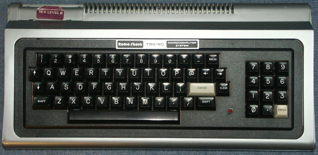
Connecting an Apple II keyboard to a computer with USB is surprisingly easy with a Teensy board. The Apple II uses an ASCII keyboard, which means that rather than returning scan codes, it returns a 7-bit ASCII value. This also means you can't read the state of modifier keys like shift or control independently. The Apple II keyboard in particular doesn't even support lower-case letters (though I've made a bit of a hack for this). They even re-use a couple alpha keys for other characters, so shift-P makes @ and shift-N makes ^. Other late 70s/early 80s home computers like the TRS-80 had a really simple layout like the Apple II's (though the TRS-80 had all four arrow keys but no Control key). I may have to try out adapting some other weird old home computers as USB keyboards -- the C-64 seems like it would be a good shape/size for that. (from afiler.com)
Arduino (Teensyduino) code is available at github.com/afiler/keyduino.
So I got the sparkfun LSM303 breakout board working last night. Trouble is the I2C bus needs not higher than 1.8v logic levels to work properly.
The level shifter is capable of doing this, but it needs a 1.8v supply to operate, hence the white wire tapping it off the breakout board.
(The two yellow wires are due to the library pinout of the arduino nano board being bad)
Compass board:
www.sparkfun.com/products/9810
Level converter:
www.sparkfun.com/products/8745
Useful library for reading data:
Arduino Academy, a 3-day summer programme for students in New Zealand, 7-9 July 2014. Catalyst IT was the organizer.
I know everyone has done this before. RFID and arduino that is. But looking at the example code it looks like the antenna is always in receive mode. I am not sure how this affects the life of the chip / reader but I thought of adding a way to detect human presence before activating the receiver.
I found some little IR heat detector (here: www.allelectronics.com/make-a-store/item/IRD-10/INFRARED-... and tossed together some analog read code and viola. Now when the IR detector detects over a certain variable heat temp it activates the RFID reader.
I will post the code and write up on my blog.
Elaborado sobre plástico flexible, este Arduino es un ejemplo de lo que se puede hacer siguiendo la técnica de David, autor del blog sewboard.cancamusa.net/