View allAll Photos Tagged arduino
Arduino clone with real-time clock, microSD socket and radio module. The layout is designed for easy assembly and maximum compatibility with the Arduino Uno, with additional functionality being compatible with the Arduino Mega2560. The optional LM61 temperature sensor is not fitted. As this particular board is intended to be powered by a boost regulator fitted to a shield the 3.3V and 5V regulators, and power LED, have not been fitted.
Version 2 features a number of improvements: there are footprints for SOIC and DIP package real-time clocks and a 5V regulator has been added. The PCB now supports the latest Arduino shield layout, with dedicated pins for I2C and IOREF signals, and 3.3V or 5V operation is possible via a jumper. An RFM12B radio module and microSD socket have been added, both are restricted to 3.3V operation. The microcontroller can be clocked from either an external crystal or ceramic oscillator. The analogue supply is smoothed with an inductor as recommended in the Atmel datasheet.
For more information see blog.stevemarple.co.uk/2012/12/calunium-version-2.html.
Eagle PCB design files available under Creative Commons Attribution-ShareAlike 3.0 Unported (CC BY-SA 3.0) licence, github.com/stevemarple/Calunium
Testen cnc-machine door te plotten - eerst maar 2d. Functie geschreven voor een spiraal.
Het onvaste kinderhanschrift van deze cnc... #arduino #cnc
the white label is todbot's arduino 'pin decoder ring' from a .pdf file. nice idea, todd! use some double sided foam tape and attach to top of chip. one layer of clear tape on the label and its good to go.
this circuit is another 'minimal arduino' that has just enough to support download of software, led-13 (usual for diagnostic and testing), a local reset button and an IR (infra red) receiver 3pin molex port.
todbot's blog post: todbot.com/blog/2009/05/23/arduino-chip-sticker-label/
to see the circuit in-use (as a volume control controller):
Space was limited in my room so I decided long ago to remove my bed and build a lofted setup.
I do a lot of tinkering so I built in a U shaped desk that extends more or less around the full perimeter of my room with lots of space to work on things. My desktop setup lies directly underneath my bed and on the opposite side I have a soldering/electronics station.
I recently underwent a few hardware upgrades for my desktop which include a liquid cooled 6 core, 64 gb RAM custom machine and 3x 27" Achieva Shimian Korean IPS displays. These are mounted to the wall with monitor arms and can be pulled closer to the edge of the table if needed. The setup works really well for my 3d modeling and coding work.
They are also backlit by a RGB LED strip powered by an Arduino R3 and Python based client on the desktop which changes color according to the color on the screens. I find that it helps a lot with eye strain and adds a great ambiance to the room.
got this in the mail before heading out of the country. can't wait to play when i get back! hoping to incorporate some sensors into my felt system just to try out different options. overall though i would like to keep it simple and minimal parts/electronics. but i also want to see what's possible.
Our third Arduino 101 class at Tam Makers went really well. I taught this evening course with co-instructor Donald Day on Thursdays, from June 16 to 30, 2016, at the woodshop in Tam High School in Mill Valley.
We worked with an enthusiastic group of seven students, including adults with diverse backgrounds, as well as a couple high school students. Our partner Geo Monley worked both as a mentor and as a student during the hands-on sessions.
We started the class at 6pm, by giving students an overview of how circuits work. We then learned how to use a multimeter, how to solder electronics, and how to control rainbow-colored NeoPixel lights.
Students seemed to really enjoy this class and told us they learned a lot from it. Several expressed an interest in taking intermediate and advanced classes in the future. This is one of our first maker courses at Tam Makers, and we’re really happy that it is going so well; we look forward to teaching more classes in the fall.
View more photos of this Arduino course:
www.flickr.com/photos/fabola/albums/72157659914570948
Learn more about this Arduino 101 class:
www.tammakers.org/arduino-101/
Read our Arduino 101 Guide:
bit.ly/arduino-101-guide-june-2016
Check out our course slides:
bit.ly/arduino-101-slides-june-2016
Learn more about Tam Makers:
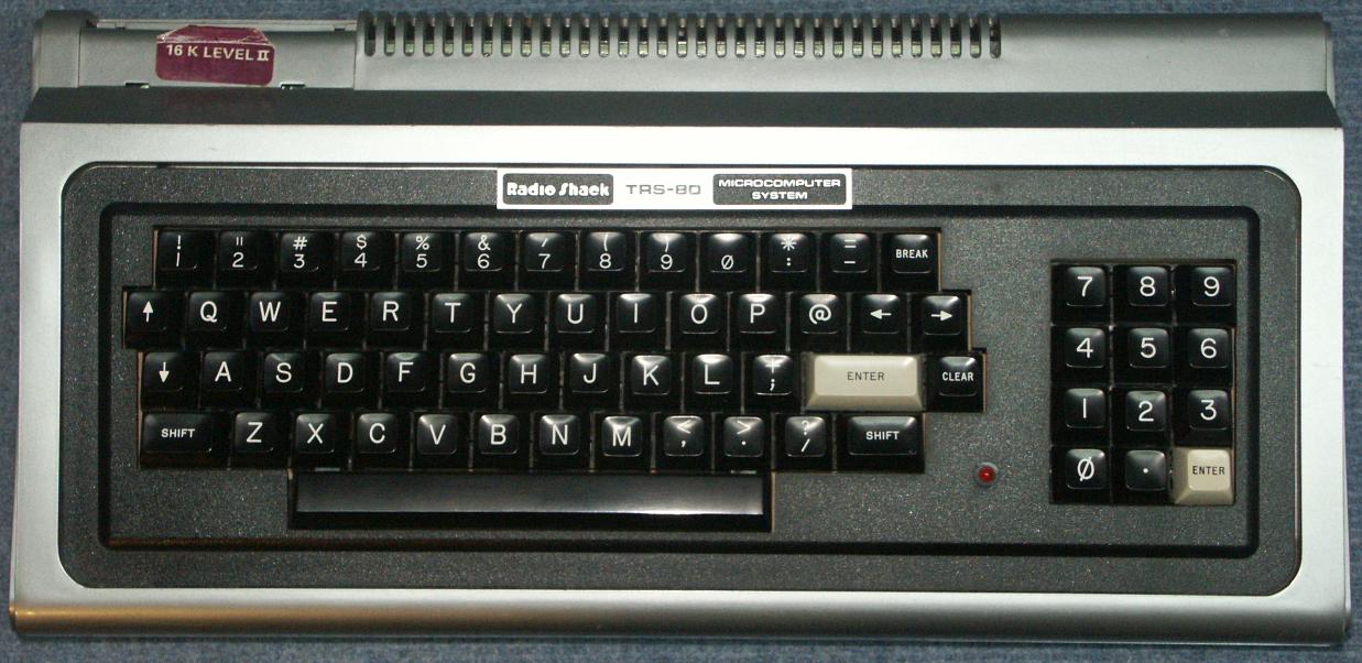
Connecting an Apple II keyboard to a computer with USB is surprisingly easy with a Teensy board. The Apple II uses an ASCII keyboard, which means that rather than returning scan codes, it returns a 7-bit ASCII value. This also means you can't read the state of modifier keys like shift or control independently. The Apple II keyboard in particular doesn't even support lower-case letters (though I've made a bit of a hack for this). They even re-use a couple alpha keys for other characters, so shift-P makes @ and shift-N makes ^. Other late 70s/early 80s home computers like the TRS-80 had a really simple layout like the Apple II's (though the TRS-80 had all four arrow keys but no Control key). I may have to try out adapting some other weird old home computers as USB keyboards -- the C-64 seems like it would be a good shape/size for that. (from afiler.com)
Arduino (Teensyduino) code is available at github.com/afiler/keyduino.
Connecting an Arduino and Raspberry Pi to create a webpage with temperature and humidity measurements.