View allAll Photos Tagged msfc
The planetary nebula Abell 30, (a.k.a. A30), is located about 5,500 light years from Earth. Close-up views of A30 show X-ray data from NASA's Chandra X-ray Observatory and optical data from the Hubble Space Telescope. A planetary nebula is formed in the late stage of the evolution of a sun-like star, after it expands to become a red giant. In the case of A30, a planetary nebula formed but then the star briefly reverted to being a red giant. The evolution of the planetary nebula then restarted, making it reborn, a special phase of evolution that is rarely seen.
Credit: X-ray (NASA/CXC/IAA-CSIC/M.Guerrero et al); Inset Optical (NASA/STScI)
#NASAMarshall #NASA #astrophysics #NASAChandra #NASA #nebula #PlanetaryNebula
Just in time for the fall foliage season, this image from the NASA/ESA Hubble Space Telescope features a glistening scene in red. It reveals a small region of the nebula Westerhout 5, which lies about 7,000 light-years from Earth. Suffused with bright red light, this luminous image hosts a variety of interesting features, including a free-floating Evaporating Gaseous Globule (frEGG). The frEGG in this image is the small tadpole-shaped dark region in the upper center-left. This buoyant-looking bubble is lumbered with two names – [KAG2008] globule 13 and J025838.6+604259.
FrEGGs are a particular class of Evaporating Gaseous Globules (EGGs). Both frEGGs and EGGs are denser regions of gas that photoevaporate less easily than the less dense gas surrounding them. Photoevaporation occurs when gas is ionized and dispersed away by an intense source of radiation – typically young, hot stars releasing vast amounts of ultraviolet (UV) light. EGGs were identified fairly recently, most notably at the tips of the iconic Pillars of Creation captured by Hubble in 1995. FrEGGs were classified even more recently and are distinguished from EGGs because they are detached and have a distinct ‘head-tail’ shape. FrEGGs and EGGs are of particular interest because their density makes it more difficult for intense UV radiation, found in regions rich in young stars, to penetrate them. Their relative opacity means that the gas within them is protected from ionization and photoevaporation. Astronomers think this is important for the formation of protostars, and that many FrEGGs and EGGs play host to the birth of new stars.
The frEGG in this image is a dark spot in the sea of red light. The red color is a type of light emission known as H-alpha emission. H-alpha occurs when a very energetic electron within a hydrogen atom loses a set amount of its energy, releasing this distinctive red light as it becomes less energetic.
Image Credit: ESA/Hubble, R. Sahai
#NASA #NASAMarshall #NASAGoddard #ESA #HubbleSpaceTelescope #HST #astrophysics #nebula
At the Marshall Space Flight Center (MSFC), the fuel tank assembly for the Saturn V S-IC-T (static test stage) fuel tank assembly is mated to the liquid oxygen (LOX) tank in building 4705. This stage underwent numerous static firings at the newly-built S-IC Static Test Stand at the MSFC west test area. The S-IC (first) stage used five F-1 engines that produced a total thrust of 7,500,000 pounds as each engine produced 1,500,000 pounds of thrust. The S-IC stage lifted the Saturn V vehicle and Apollo spacecraft from the launch pad. This July, in a series of special events, NASA is marking the 50th anniversary of the Apollo Program – the historic effort that sent the first U.S. astronauts into orbit around the Moon in 1968, and landed a dozen astronauts on the lunar surface between 1969 and 1972. For more pictures, and to connect to NASA’s remarkable history, visit the Marshall History Program’swebpage.
Image credit: NASA
Pulsar wind nebulas like MSH 15-52 are clouds of energetic particles, producing X-rays, that are driven away from dead collapsed stars. X-rays from NASA's Chandra X-ray Observatory (gold and blue); infrared from the Dark Energy Camera KPNO Blanco 4.0m (red and blue)
In this composite image, a pulsar, a pulsar wind nebula, and a low energy X-ray cloud combine to create an uncanny scene of a skeletal hand preparing to grab a glowing ember. The hand reaches up from the bottom of the image, the ghostly blue flesh and white bones representing pulsar wind nebula X-rays observed by Chandra. A bright white spot in the wrist is the pulsar itself. Just beyond the hand’s fingertips, near our upper right, is a mottled yellow and orange shape that appears to glow from within. This is the low energy X-ray cloud observed by Chandra.
Credit: X-ray: NASA/CXC/SAO; Optical: NOIRLab/DECam; Image processing: NASA/CXC/SAO/J. Schmidt
#NASAMarshall #NASA #astrophysics #NASAChandra #NASA #nebula
The fourth and final structural test article for NASA’s Space Launch System (SLS) core stage was unloaded from NASA’s barge Pegasus at NASA’s Marshall Space Flight Center in Huntsville, Alabama, Tuesday, July 9, 2019. The nearly 70-foot-long liquid oxygen (LOX) tank structural test article was manufactured at NASA’s Michoud Assembly Facility in New Orleans and is structurally identical to the flight version. Next, crews will load it into a test stand at Marshall for critical testing. The liquid oxygen tank is one of two propellant tanks in the rocket’s core stage that will produce more than 2 million pounds of thrust to help launch Artemis 1, the first flight of NASA’s Orion spacecraft and SLS, to the Moon.
Image credit: NASA/Fred Deaton
NASA’s next big eye on the cosmos is now fully assembled. On Nov. 25, technicians joined the inner and outer portions of the Nancy Grace Roman Space Telescope in the largest clean room at the agency’s Goddard Space Flight Center in Greenbelt, Maryland.
This image shows the Nancy Grace Roman Space Telescope is now fully assembled following the integration of its two major segments on Nov. 25 at the agency’s Goddard Space Flight Center in Greenbelt, Md. The mission is slated to launch by May 2027, but the team is on track for launch as early as fall 2026.
Image Credit: NASA/Jolearra Tshiteya
#NASA #NASAMarshall #MSFC #NASAGoddard #NancyGraceRomanSpaceTelescope #astronomy #astrophysics
The spiral galaxy UGC 11860 seems to float serenely against a field of background galaxies in this image from the NASA/ESA Hubble Space Telescope. UGC 11860 lies around 184 million light-years away in the constellation Pegasus, and its untroubled appearance is deceiving; this galaxy recently played host to an almost unimaginably energetic stellar explosion.
A supernova explosion – the catastrophically violent end of a massive star’s life – was detected in UGC 11860 in 2014. Astronomers used Hubble’s Wide Field Camera 3 to search through the aftermath and analyze the lingering remnants of this vast cosmic explosion.
One team explored UGC 11860 to understand more about the star systems that eventually meet their demise in supernovae. The hugely energetic processes during supernova explosions are predominantly responsible for forging the elements between silicon and nickel on the periodic table. This means that understanding the influence of the masses and compositions of the progenitor star systems is vital to explaining how many of the chemical elements here on Earth originated.
Image Credit: ESA/Hubble & NASA, A. Filippenko, J. D. Lyman
#NASA #NASAMarshall #NASAGoddard #ESA #HubbleSpaceTelescope #HST #astrophysics #galaxy
Firefly Aerospace’s Blue Ghost Mission One lander, seen here, will carry 10 NASA science and technology instruments to the Moon’s near side when it launches from NASA’s Kennedy Space Center in Florida on a SpaceX Falcon 9 rocket, as part of NASA’s CLPS (Commercial Lunar Payload Services) initiative and Artemis campaign.
Under the CLPS model, NASA is investing in commercial delivery services to the Moon to enable industry growth and support long-term lunar exploration. As a primary customer for CLPS deliveries, NASA aims to be one of many customers on future flights.
As part of its Artemis campaign, NASA is working with multiple U.S. companies to deliver science and technology to the lunar surface.
Credit: Firefly Aerospace
#NASAMarshall #NASA #NASA #moon #CLPS #CommercialLunarPayloadServices #Lander #LunarLander
Read more about NASA’s CLPS (Commercial Lunar Payload Services)
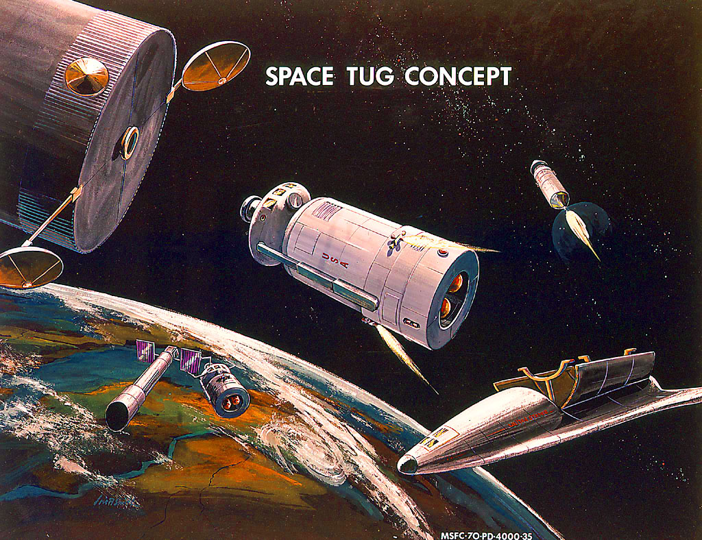
“SPACE TUG CONCEPT”
“Space Tug: Boeing
The Boeing Space Tug is a modular design. This concept was later developed into the NASA Space Tug. One way to tell the difference is that the Boeing tug's crew and cargo modules were spherical, while the NASA tug's modules were cylindrical.”
The above & image at/from
www.projectrho.com/public_html/rocket/spacetug.php#spacetug
Specifically:
www.projectrho.com/public_html/rocket/images/realdesigns/...
Credit both above: ATOMIC ROCKETS website
The signature looks to be that of Lois A. Smith, hence my posting, and therefore, a WIN. Please see my other postings of the few works of hers that I’ve come upon/identified. A talented & genuine trailblazer she was!
On Nov. 1, NASA's Lucy spacecraft flew by not just its first asteroid, but its first two. The first images returned by Lucy reveal that the small main belt asteroid Dinkinesh is actually a binary pair.
This image shows the "moonrise" of the satellite as it emerges from behind asteroid Dinkinesh as seen by the Lucy Long-Range Reconnaissance Imager (L'LORRI), one of the most detailed images returned by NASA's Lucy spacecraft during its flyby of the asteroid binary. This image was taken at 12:55 p.m. EDT (1655 UTC) Nov. 1, 2023, within a minute of closest approach, from a range of approximately 270 miles (430 km). From this perspective, the satellite is behind the primary asteroid. The image has been sharpened and processed to enhance contrast.
Credit: NASA/Goddard/SwRI/Johns Hopkins APL/NOIRLab
#nasa #msfc #marshallspaceflightcenter #GoddardSpaceFlightCenter #Goddard #GSFC #lucypacecraft #trojans #trojanasteroids #Dinkinesh
The star-forming region, 30 Doradus, is one of the largest located close to the Milky Way and is found in the neighboring galaxy Large Magellanic Cloud. About 2,400 massive stars in the center of 30 Doradus, also known as the Tarantula Nebula, are producing intense radiation and powerful winds as they blow off material. Multimillion-degree gas detected in X-rays by NASA's Chandra X-ray Observatory comes from shock fronts formed by these stellar winds and by supernova explosions.
Credit: X-ray: NASA/CXC/PSU/L.Townsley et al.; Infrared: NASA/JPL/PSU/L.Townsley et al.
#NASAMarshall #NASA #astrophysics #NASAChandra #NASA #JWST #NASAWebb #star #nebula
On April 1, 1983, divers and astronauts at NASA's Marshall Space Flight Center in Huntsville, Alabama, prepared for the first satellite repair mission in space. Before the repair, the crew of Space Shuttle Challenger mission STS-41C spent months at the Marshall Center Neutral Buoyancy Simulator, an underwater training facility that is now a historic landmark. They used a mockup of the Solar Maximum satellite to practice retrieving the satellite and piloting a new Manned Maneuvering Unit (MMU), which allowed astronauts to travel in space without being tethered to the shuttle. About a year after this picture was taken, on April 6, 1984, Space Shuttle Challenger (STS-41C) launched on a mission to repair the Solar Max satellite. Solar Max was designed to study the sun but had a systems failure about a year after it was launched. The STS-41C crew chalked up a number of firsts for NASA: the first satellite retrieval, the first service use of a MMU and the Remote Manipulator System, and all of this on the Space Shuttle Challenger's first space flight. The crew retrieved Solar Max, repaired it, and placing it back in service. The Solar Maximum Repair mission provided engineers with valuable data that helped them design the Hubble Space Telescope for on-orbit repair and maintenance.
Credit: NASA
Image Number: MSFC-8334107
Date: April 1, 1983
Striking 1970 NASA/MSFC artist’s depiction of a “Mars Base”.
I presume as part of NASA’s grand Integrated Program Plan (IPP). Good regarding the IPP:
spaceflighthistory.blogspot.com/2016/01/thinking-big-traf...
Credit: David S. F. Portree/“No Shortage of Dreams” blog
And:
www.nasa.gov/sites/default/files/atoms/files/19690804_man...
Although of a different writing style, i.e., block letters, the artist’s signature, “L A Smith”, must surely be Lois Virginia Archambeault Smith. I mean, how many “L. A. Smith” NASA/MSFC artists could there have been in 1970? Another WIN WRT Ms. Smith!
With sincerest appreciation to J. L. Pickering for making the image available. And, if you want to see but a mere fraction of the world’s preeminent collection of space photographs, I HIGHLY advise you to explore Mr. Pickering’s FB presence. Prepare to be blown away:
And/or Twitter:
And/or YouTube:
www.youtube.com/c/RetroSpaceHD
And/or his website:
The first integrated 3D printer and recycler is part of the cargo that was launched to the International Space Station on Northrop Grumman’s Cygnus spacecraft’s 10th commercial resupply services mission. The machine, known as Refabricator, will demonstrate the capability to turn waste plastic and previously 3D printed parts into high-quality 3D printer filament (3D printing “ink”) to create new tools and materials. The demonstration will use control plastic recycled multiple times to create parts that will be tested for quality back on Earth.
Image credit: NASA/Emmett Given
My entry for the MSFC on Eurobricks it's a micro dio of a Beam emitter complete with a tiny Pelican dropship from Halo.
“SHUTTLE ALT CRAFT AT MSFC ---- The Space Shuttle Orbiter 101 “Enterprise” riding atop its 747 carrier aircraft, arrives at the Redstone Arsenal airstrip near Marshall Space Flight Center (MSFC), Huntsville, Alabama, on March 13, 1978. It is to undergo ground vibration tests along with the external tank and solid rocket boosters, preparatory to Orbiter Flight Tests (OFT) in which its successor craft (Orbiter 102) will take several two-man crews into earth orbit.”
A wonderful perspective most often seen of the combination landing at KSC or EAFB, not MSFC…cool.
Win one of these in the Micro Sci-Fi Contest on Eurobricks!
First Place: 70701 Swarm Interceptor + 1st choice of MSFC Trophy
Second Place: 70700 Space Swarmer + 2nd choice of MSFC Trophy
Third Place: 2x CMF (Space Marine or Evil Robot) + Trophy
Posted primarily for my own edification, to serve as a ‘marker’ for possible/hopeful future identification of the artist responsible. Note what appears to be “M.R.” in the lower right-hand corner of Quadrant I of the LM descent stage. Although I’m confident of the “M” & “R”, I might be off regarding the markings to the right of each letter. I’m guessing accentuated/stylized(?) periods. Or, maybe not. Who knows.
Regardless, it's by an MSFC artist, in 1967, with the initials M.R.
For the Eurobricks Micro Sci-Fi Contest (MSFC).
High above the clouds, mysterious floating rocks were discovered by a trainer taking his dragon Pokémon to never before seen heights. With this amazing new discovery, came an incredible new place for Pokémon battling at the Sky-Fi Stadium, which was built shortly after the discovery of the rocks. Sky-Fi stadium features seating for over 100,000, advanced training platforms, watch towers, and everything else you could possibly need!
“As part of the Space Task Group's recommendations for more commonality and integration in America's space program, Marshall Space Flight Center engineers proposed an orbiting propellant storage facility to augment Space Shuttle missions. In this artist's concept from 1969 an early version of the Space Shuttle is shown refueling at the facility.”
8.5" x 11".
Above, and in color, at:
archive.org/details/MSFC-9902021
Credit: Internet Archives website (always outstanding!)
With five, count ‘em, FIVE (5) engines, the distinctive, massive, yet elegant delta-shaped lifting body appears to be Lockheed’s Phase A design study of the timeless STAR Clipper. It’s obvious why this & variations of it were the “go-to” design depicted in a slew of artist’s concepts during the late 1960s/early 1970s:
www.pmview.com/spaceodysseytwo/spacelvs/sld019.htm
Specifically:
sites.google.com/site/spaceodysseytwo/stg1969/sclppr69.jpg
Credit: PMView Pro website
As if all of the above weren’t enough! It’s one of many beautiful & diverse works by NASA artist Renato Moncini…amazing:
www.nasa.gov/sites/default/files/atoms/files/art_of_the_i...
This is a wonderful document btw.
www.facebook.com/therenatomoncinistory/
scontent-ort2-2.xx.fbcdn.net/v/t31.18172-8/fr/cp0/e15/q65...
Credit: Facebook
vdocuments.net/fete-july-2013.html
Credit: ‘World Documents’ website
www.southcarolinapublicradio.org/sc-news/2019-02-01/green...
Credit: South Carolina Public Radio website
www.greenvilleonline.com/story/news/local/greenville/city...
Credit: Greenville News website
www.lavocedelserchio.it/vediarticolo.php?id=16970&pag...
Credit: La Voce del Serchio website
www.rrauction.com/auctions/lot-detail/336087704866552-pai...
Credit: RR Auction website
www.invaluable.com/auction-lot/renato-moncini-painting-of...
Credit: Invaluable website
The spectacular aurora borealis, or the “northern lights,” over Canada is sighted from the International Space Station near the highest point of its orbital path. The station’s main solar arrays are seen in the left foreground. This photograph was taken by a member of the Expedition 53 crew aboard the station on Sept. 15, 2017.
Image Credit: NASA
To follow NASA astronauts on twitter, click here.
“SAMSP---An artist’s rendering of the Science and Applications Manned Space Platform (SAMSP), one of several space station concepts under study by MSFC. The manned platform, a structure that would allow people to live and work in space, represents an evolution from the Space Platform, proposed for later in this decade, which would support scientific and applications experiments with electrical power and other services. Four or more crewmembers on 90-day assignments could live in habitability modules which would be installed in the berthing ports of the platform. As other such modules were added crew sizes could be increased and working schedules overlapped to provide a manned permanent presence in space. At one end of the platform, two astronauts are depicted constructing a communications satellite. A nearby remote manipulator system assists the crewmembers in extravehicular activity (EVA). A hangar protects an upper-stage rocket for transferring payloads from one orbit to another. Connected to the upper stage is a workstation where astronauts may plan and observe the actions of co-workers performing EVAs. On the opposite side of the workstation is a teleoperator maneuvering system resting in the half-circle pallet. Also under study now at Marshall, the maneuvering system would move payloads around in low Earth orbit and perform satellite servicing by remote control. Connected to the workstation is an airlock. A cylindrical Logistics Module, above the airlock, supplies the astronauts with air, water, clothing and other living needs. The entire cluster of modules connects to the Space Platform. Wing-like solar arrays provide electrical power to the entire system. The tall plate between the solar arrays is the heat radiator. One Shuttle awaits nearby, having just arrived with a fresh Logistics Module and new experiments for the berthing ports.”
Note also what appears to be a telescope of some sort mounted to the Spacelab-like pallet ‘berthed’ to the core module/hub.
I believe the “teleoperator maneuvering system” was later referred to as the Orbital Maneuvering Vehicle (OMV):
www.astronautix.com/o/omv.html
Credit: Astronautix website
Also, associated with the fourth image, a crop:
“This illustration from 1981 depicts the assembly of a large telecommunications antenna (right) at the Science & Applications Manned Space Platform.”
At/from:
www.pmview.com/spaceodysseytwo/station/sld004.htm
Credit: PMView Pro website
And:
“American manned space station.
While NASA/Johnson was studying the Space Operations Center concept, the Marshall Space Flight Center was lobbying for its own station -- the Science and Applications Manned Space Platform (SAMSP).
Status: Study 1980.
MSFC envisioned a series of cheap 'platforms' costing only $500 million that could be outfitted for different missions. One mission would be to service spacecraft such as the Hubble Space Telescope. The platform would provide power, communications, thermal control and other services for standard Shuttle payload experiments -- it essentially served as a surrogate Shuttle payload bay. SAMSP could gradually evolve into a manned space station by adding pressurized crew modules derived from Spacelab. Initially, SAMSP would have a crew of three to four astronauts.
NASA/Marshall issued a number of Science and Applications Manned Space Platform contracts to McDonnell-Douglas and TRW in 1980. A 1981 unmanned TRW platform design carried three Spacelab unpressurised experiment pallets, including a space telescope. Two large solar panel 'wings' generated power while the radiator dumped excess heat produced by the experiments. The unmanned TRW platform could be customized for different missions. The TRW platform could be transformed into a human-tended microgravity laboratory by adding Spacelab pressurized modules. These would contain sensitive experiments and be replaced at regular intervals by visiting Space Shuttles.
Article by Marcus Lindroos”
At, also with the cropped image:
www.astronautix.com/s/scienceandaspaceplatform.html
Credit: Astronautix website
Finally:
“A large antenna is under construction in this concept of a space station by McDonnell Douglas Astronautics Co., designed under contract with NASA.”
At, with the full image, on page 14:
docshare01.docshare.tips/files/4606/46060281.pdf
Credit: “NASA Space Station” (EP-211), 1985, by David A. Anderton
As if all of that wasn't enough...it's by NASA/MSFC artist Euel “Dean” Cagle. A beautiful & detailed work and another WIN.
Despite my initial justified doubt regarding the “communications satellite"/“large antenna", I suppose the presence of a subreflector & feed cone confirms it being an antenna. So then, A ‘communications’ antenna…as part of a “satellite”? It sure doesn’t look like a satellite. It looks like it’s attached to/at the end of the truss. Who knows/cares:
ntrs.nasa.gov/api/citations/19890014145/downloads/1989001...
Or, it's a telescope...way ahead of it's time if so. Check this out, the JWST. It's gorgeous and pretty much a spitting image:
scienceworld.scholastic.com/content/dam/classroom-magazin...
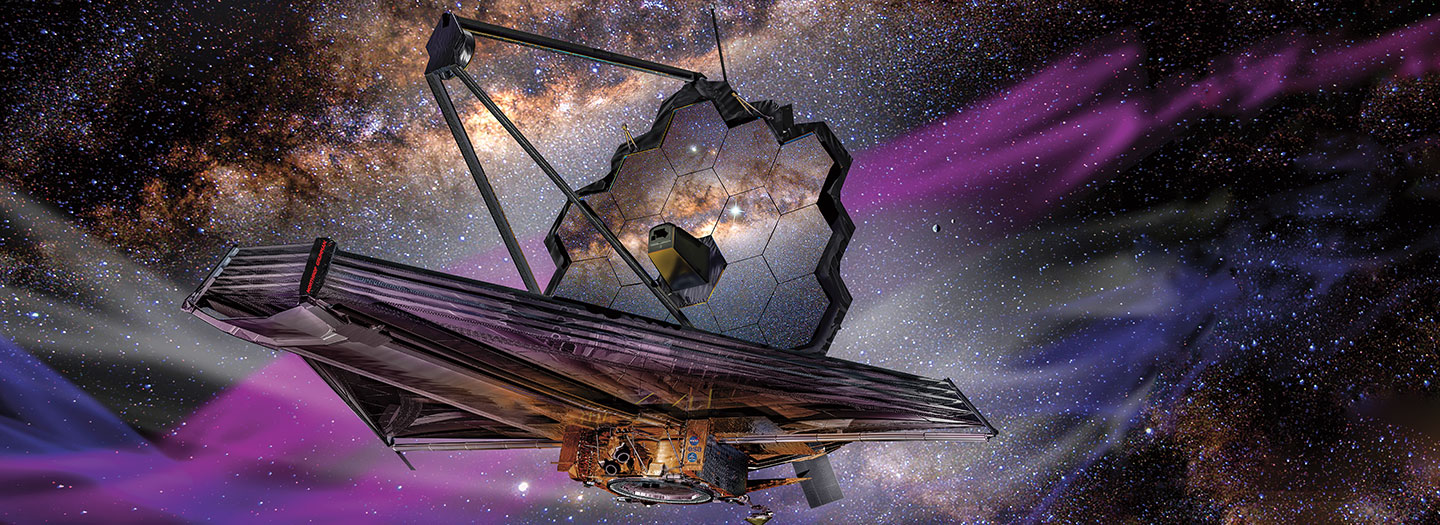
Credit: James Vaughan/Science World/Scholastic website
And, get this, the Mr. Vaughan cited is none other than that of 'x-ray delta one' fame, here on this image hosting "service":
www.flickr.com/photos/x-ray_delta_one/albums
Wow:
An amazingly talented gentleman.
well in my interview last week josh asked if my micro apollo was for a contest, got me thinking, here is V2
Editor's note: Hello, Flickr friends! A beautiful composite of the peak night of the 2012 Perseid meteor shower, courtesy of our astronomers here at the Marshall Center. The image is lightly colorized to give it a soft blue tint, but otherwise this is au naturel. This is why we get excited and stay up all night to watch the meteor showers. :)
The image shows the skies over NASA Marshall Space Flight Center in Huntsville, AL USA during the peak night of the Perseids. Over 100 individual meteor images were combined to create this composite. The linear streaks are meteors, most of them Perseids, the dotted arcs are stars, and the brightest arc on the left side is the moon. We saw some real beauties!!
Image credit: NASA/MSFC/MEO
Original image:
www.facebook.com/NasaMeteorWatch
View more meteor photos!
www.flickr.com/photos/nasamarshall/sets/72157607380035209/
_____________________________________________
These official NASA photographs are being made available for publication by news organizations and/or for personal use printing by the subject(s) of the photographs. The photographs may not be used in materials, advertisements, products, or promotions that in any way suggest approval or endorsement by NASA. All Images used must be credited. For information on usage rights please visit: www.nasa.gov/audience/formedia/features/MP_Photo_Guidelin...
“Saturn SA-1
Open house – 1961
Manufacturing Engineering Div
Marshall Space Flight Center
Huntsville, Alabama”
The above is beautifully handwritten by pen, in cursive, on the verso. Obviously by someone intelligent, articulate, possessing excellent penmanship and MOST importantly, ‘in the know’. Therefore, SA-1 it is. Which is what I assumed, despite not a single bit of documentation, etc., that I’ve come across that clearly states such.
Several (of the few) sources have namby-pamby descriptions/wording of the iconic views of the rocket in this horizontally ‘assembled’ & displayed state – that can be interpreted to imply that it’s SA-1…kinda/sorta/maybe.
But, if it's not...oh well. At least I made a legitimate attempt. Which is more than I can say about those whose responsibility it was/should’ve been.
The “Space Launch Report” website, the LONE site which actually referred to it as SA-1 is history, the domain having expired. A HUGE loss for someone such as myself, or anyone else conscientiously attempting to accurately catalog & preserve NASA photographic history…which obviously exceeds their ability/capability.
The caption affixed to another very similar black & white NASA-MSFC issued photograph, date stamped “JUL 7 ‘61” reads as follows:
An estimated 45,000 to 50,000 persons streamed through the George C. Marshall Space Flight Center, NASA, during the Center's "Space Day" open house, commemorating the first anniversary of the establishment of the Center. In this picture, visitors view a three-stage Saturn C-1 in an assembly hangar. This rocket is identical to the first Saturn which will be launched later this year.
And finally, from the May 1974 iteration of “AN ILLUSTRATED CHRONOLOGY OF THE NASA MARSHALL CENTER AND MSFC PROGRAMS 1960-1973”:
An estimated 45,000 to 50,000 "Space Day" visitors attended MSFC's first open house on July 1. Attending were such national figures as the NASA Administrator James E. Webb; the Director of NASA Launch Vehicle Programs, Maj. Don Ostrander; and numerous other national state, and local dignitaries. Most of the visitors observed one of the four Saturn H-1 engine static firings during the day.”
A rare, delightful unicorn containing valuable (IMHO) historical information, and brimming with wonderful nostalgia. And it’s on that exquisite super-duper smooth glossy film-like ‘paper’. You really gotta see/feel it to appreciate it…seriously.
The two exaggeratedly rectangular, tripod-mounted cameras (to the lower right) look to be, to me, Polaroid Pathfinders (110/110A/110B/120?), or 800’s maybe? It even looks like the fellow is either loading film or about to pull an exposed ‘shot’ out of one of them.
camerapedia.fandom.com/wiki/Polaroid_Pathfinder
Credit FANDOM/CAMERAPEDIA website
Finally, note the congregation of primarily males, their attention focused on the fetching young lady wearing the “SPACE(?) PRINCESS” sash. And to her right appears to be a queen and another sash-wearing “SPACE(?) PRINCESS”. So, obviously, the queen and her court…possibly from an on-site(?) MSFC parade earlier in the day.
In another first for NASA, an all-female crew of scientific experimenters began a five-day exercise on December 16, 1974, to test the feasibility of experiments that were later tested on the Space Shuttle/Spacelab missions. The experimenters, Dr. Mary H. Johnston (seated, left), Ann F. Whitaker and Carolyn S. Griner (standing, left to right), and the crew chief, Doris Chandler, spent spend eight hours each day of the mission in the Marshall Space Flight Centers General Purpose Laboratory (GPL). They conducted 11 selected experiments in materials science to determine their practical application for Spacelab missions and to identify integration and operational problems that might occur on actual missions.
Credit: NASA
Image Number: 565782
Date: November 13, 1974
“The Shuttle Orbiter Enterprise inside of Marshall Space Flight Center's (MSFC) Dynamic Test Stand for Mated Vertical Ground Vibration Tests (MVGVT). The tests marked the first time ever that the entire shuttle complement including Orbiter, External Tank, and Solid Rocket Boosters were vertically mated.”
The above is taken from a very similar image, attributed with a date of 6 October 1978, and linked to below.
Also, the same image, attributed with the date of 6 October 1978:
“The first complete Space Shuttle launch vehicle ever assembled was mated in the Marshall Space Flight Center, Huntsville, Ala. Dynamic Test Stand in October 1978 for the second phase of the ground vibration tests. Here, the orbiter and solid rocket motors are mated to the huge external tank for testing that verified that the Shuttle would perform as predicted during launch.”
So, a very nice photograph, of a quietly historic Space Shuttle Program milestone that…ONE GUESS - that’s right - is LEFT-TO-RIGHT REVERSED. Why not? The ignominious tradition lives on. At least they managed to stumble upon 'right' in other photos of this event.
Lots of nice photos, some pertinent to this one:
forum.nasaspaceflight.com/index.php?topic=35828.240
Credit: NASA Spaceflight Forum website
Also:
www.nasa.gov/feature/40-years-ago-space-shuttle-enterpris...
“On 10 June 1977, former Skylab Deputy Director John Disher, NASA's Director of Advanced Programs, directed NASA Marshall Space Flight Center (MSFC) in Huntsville, Alabama, to conduct an in-house study of the feasibility of reusing Skylab in the Space Shuttle program. On 16 November 1977, MSFC engineers J. Murphy, B. Chubb, and H. Gierow presented results of the study to NASA Associate Administrator for Space Flight John Yardley. Before coming to NASA in 1974, Yardley had managed Skylab assembly at McDonnell Douglas, the Orbital Workshop's prime contractor.
The MSFC engineers first assessed Skylab's condition. They reported that when the Skylab 4 crew returned to Earth, the Orbital Workshop's water system contained 1930 pounds of water (enough to supply three men for 60 days). The water, they said, probably remained potable, but could have developed a bad taste. If not still potable, it could be used for bathing. In any case, the Skylab water system included resupply points, so a Space Shuttle crew could replenish it if water transfer equipment were developed.
The oxygen/nitrogen supply remaining on Skylab was probably sufficient to supply three men for 140 days at Skylab's operating pressure of five pounds per square inch, the MSFC engineers estimated. The ventilation and carbon dioxide removal systems were almost certainly functional. Even if they were not, their most important components were designed to be replaceable in space.
The MSFC engineers also assessed Skylab's electrical power system. They estimated that the main solar array Conrad and Kerwin had freed could still generate between 1.5 and 2.5 kilowatts (KW) of electricity, and that the batteries it had charged, located in Skylab's Airlock Module, were probably still usable. The batteries for the ATM arrays, on the other hand, were almost certainly frozen. They recommended that controllers reactivate the main array electrical system from the ground before the first Shuttle visit, and that any effort to revive the ATM electrical system be left until a later time.
More problematic than the electrical system was the attitude control system, which relied on a trio of Control Moment Gyros (CMGs) to turn Skylab so that, among other things, it could point its solar arrays at the Sun. One CMG had failed and another showed signs of impending failure. In addition, Skylab's guidance computer was probably dead after being subjected to "extreme thermal cycling." The Orbital Workshop's thruster system, on the other hand, was probably operational with about 30 days of propellant remaining.
Finally, the MSFC team looked at Skylab's cooling system, which had leaked while the astronauts were on board and had probably frozen and ruptured since the last crew returned to Earth. They called "serviceability of [the] cooling system. . .the most questionable area" as far as Skylab's reusability was concerned, but added that "any inflight 'fixes' should be well within the scope of crew capability."
The MSFC engineers then proposed a four-phase plan for reactivating and reusing Skylab. The target date for the first Phase I milestone had already passed by the time they briefed Yardley: they called for an October 1977 decision on whether Skylab should be reboosted to a higher orbit, extending its orbital lifetime until about 1990, or deboosted so that it would reenter over an unpopulated area.
Assuming that NASA decided to reboost Skylab, then a ground reactivation test would occur between June 1978 and March 1979. If the reactivation test was successful, then a Space Shuttle Orbiter would rendezvous with Skylab during the Shuttle Program's fifth Orbital Flight Test mission in February 1980. The Orbiter would conduct an inspection fly-around, then deploy an unmanned Teleoperator spacecraft from its payload bay. Using a control panel on the Shuttle, the astronauts would guide the Teleoperator, which would carry an Apollo-type probe docking unit, to a docking with the front docking port on Skylab's Multiple Docking Adapter. The Teleoperator would then fire its thrusters to raise Skylab's orbit. Its work done, it would then detach, freeing up the front port for Phase II of MSFC's plan.
Phase II would begin in March 1980, when NASA would initiate development of Skylab refurbishment kits, a 10-foot-long Docking Adapter (DA), and a 25-KW Power Module (PM). The DA would include at one end an Apollo-type probe docking unit for attaching it to Skylab's front port and at the other end an Apollo-Soyuz-type androgynous unit to which Shuttle Orbiters and the PM could dock.
The first refurbishment kit and the DA would reach Skylab on board a Shuttle Orbiter in January 1982. During the same mission, spacewalking Shuttle astronauts would fold two of the four ATM solar arrays to improve clearance for visiting Orbiters and would retrieve the meteoroid experiment the Skylab 4 astronauts had left on the ATM.
A second Shuttle visit in August 1983 would bring additional refurbishment kits and would repair Skylab's damaged cooling system plumbing. As time allowed, the Phase II crews would perform undefined "simple passive experiments" on board Skylab and would collect samples of its structure for analysis on Earth.
Phase III would begin in March 1984 with delivery of the PM and any remaining refurbishment kits, the MSFC engineers told Yardley. Using the Shuttle's Remote Manipulator System robot arm, astronauts would lift the PM from the Orbiter's payload bay and turn it 180° so that it protruded forward well beyond the Orbiter's nose. They would then dock one of the PM's three androgynous docking units to an identical unit at the front of the Orbiter's payload bay. The Shuttle would use another of the PM's docking units to dock with the DA on Skylab.
Following docking with Skylab, the astronauts would deploy the PM's twin solar arrays and thermal radiators, link it to Skylab's systems by cables extended through open hatchways or installed on the hull during spacewalks, and power up the PM's three CMGs to replace Skylab's crippled attitude control system. The Orbiter would then undock from the PM, leaving it attached permanently to Skylab, and NASA would declare the revived and expanded Orbital Workshop to be fully habitable.
Phase III would continue with the first in a series of 30-to-90-day missions aboard Skylab. During these, a Shuttle Orbiter carrying a Spacelab module in its cargo bay would remain docked with the Orbital Workshop. The astronauts would work in the Spacelab module, take advantage of Skylab's large pressurized volume to perform "simple experiments" requiring more room than Shuttle and Spacelab could provide (for example, preliminary space construction experiments), and begin building up stockpiles of food, film, clothing, and other supplies on board. Another 30-to-90-day mission would see the astronauts refurbish and use selected Skylab science experiments, install new experiments based on Spacelab experiment designs, and stockpile more supplies. Between these missions, the new and improved Skylab would fly unmanned.
The MSFC engineers told Yardley that the volume available to a crew on board a Shuttle Orbiter without a Spacelab module in its payload bay would total only 1110 cubic feet. Adding a Spacelab would increase that to about 5100 cubic feet. This was, however, less than half the pressurized volume of Skylab. For a mission including a Shuttle Orbiter, Spacelab module, and Skylab, the total volume available to the crew would exceed 16,400 cubic feet.
They were not specific about what Skylab would be used for when Phase IV began in mid-1986, though they did offer several intriguing possibilities. Shuttle Orbiters might, for example, attach Spacelab modules and experiment pallets to the third docking port on the PM. A Shuttle External Tank might be joined to Skylab to serve as a strongback for large-scale space construction experiments using a mobile "space crane." The experiments might include construction of a large space power module or a multiple beam antenna. A new "floor" might be assembled within Skylab, enabling it to house up to nine astronauts. As NASA developed confidence in the revived space laboratory's health, manned missions on board Skylab without a Shuttle Orbiter present might commence, leading to permanent manning and "support [of] major space operations."
The MSFC engineers did not estimate the cost of Phases I and IV of their plan, though they did provide a (perhaps optimistic) pricetag for Phases II and III. Their estimate did not include Space Shuttle transportation and contractor study costs. In Fiscal Year (FY) 1980, NASA would spend $2 million each on Phases II and III. This would climb to $5 million for Phase II and $3.4 million for Phase III in FY 1981. FY 1982, the plan's peak funding year, would see $4.5 million spent on Phase II and $10.2 million spent on Phase III. In FY 1983, NASA would spend $2.5 million to close out Phase II and $12 million to continue Phase III. The following year it would spend $9.1 million on Phase III. Phase III closeout in FY 1985 would cost $4.5 million. Phase II would cost a total of $14 million, while the more ambitious Phase III would total $41.2 million. Phases II and III together would cost $55.2 million.
MSFC's presentation to Yardley concluded with a call for more in-house and contractor studies in FY 1978. McDonnell Douglas and Martin Marietta subsequently began more detailed Skylab reuse studies, the former under supervision of NASA Johnson Space Center in Houston, Texas, and the latter under MSFC supervision. The Martin Marietta and McDonnell Douglas studies will be discussed in forthcoming posts.
Reference:
Skylab Reuse Study Presented to Mr. Yardley by MSFC, November 16, 1977.”
The above superb article, as are so so many others – thankfully - at:
spaceflighthistory.blogspot.com/2015/11/reviving-reusing-...
In addition to:
spaceflighthistory.blogspot.com/2015/11/
Credit: DSFP's SPACEFLIGHT HISTORY blog/David S. F. Portree
Also, a condensed write-up at:
www.astronautix.com/s/sts-2a.html
Credit: Astronautix website/Mark Wade
Sadly, an opportunity lost.
Saturn V/ Apollo Service Module (MIX FILE) (REF3 MSFC-68-MS-G-1336E
Artwork by Rosemary A. Dobbins
With thanks to Garrett O'Donoghue/"numbers station" blog for jogging my memory with his excellent post at:
e05.code.blog/2022/03/08/apollo-csm/#jp-carousel-6912
BTW, Rosemary Dobbins’ daughter: YOU’RE WELCOME.
NASA’s Mars Ascent Vehicle (MAV) recently reached some major milestones in support of the Mars Sample Return program. The Mars Ascent Vehicle would be the first launch of a rocket from the surface of another planet. The team developing MAV conducted successful tests of the first and second stage solid rocket motors needed for the launch.
Mars Sample Return will bring scientifically selected samples to Earth for study using the most sophisticated instrumentation around the world. This strategic partnership with ESA (European Space Agency) features the first mission to return samples from another planet. The samples currently being collected by NASA's Perseverance Rover during its exploration of an ancient river delta have the potential to reveal the early evolution of Mars, including the potential for ancient life.
In this image, a development motor based on the second-stage solid rocket motor design for NASA’s Mars Ascent Vehicle undergoes testing March 29, 2023, at Northrop Grumman’s facility in Elkton, Maryland. The two-stage MAV rocket is an important part of the joint plan between NASA and ESA to bring scientifically-selected Martian samples to Earth in the early 2030s.
Image credit: NASA
#NASA #MarshallSpaceFlightCenter #MSFC #rocket #space #Perserverance #Mars2020Rover #Mars #MarsSampleReturnProgram #MarsAscentVehicle
More about the Mars Ascent Vehicle
Three unidentified VIPs?, politicians?…who knows…posing with an early unidentified, horizontally positioned Saturn I/C-1 within the Fabrication and Assembly Engineering Division, MSFC. Circa 1961/62? The clutter-free work tables in the foreground may be indicative of an impending & requisite “dog & pony” show, of which the three gentlemen might’ve been/will be participants/attendees?
To that point, when this photograph was taken, there was indeed a lot riding on WHAT’S going on here, and HOW WELL it was going on, with many stakeholders involved.
Also, note the two adjacent display/announcement boards to the far left, with a smaller narrow board centered atop them, (which I was able to resolve in another photograph) that bears "THE TEAM BEHIND THE SATURN". So, the checkerboard appearance of the large boards consists of the logos of the contributing contractors & sub-contractors.
Finally & pointlessly, I think the spoked circular things at the far right are the ends of H-1 engine holders/cradles/dollies/transporters...or whatever they’re called.
The photo is also at, accompanied by generic pablum statements which provide no pertinent information WRT this particular photograph. Maybe because no initial record or annotation accompanied it(?), subsequently, probably because nobody had/has a clue, and surely in the future, because nobody will give a flying [fill in the blank]:
www.nasa.gov/centers/marshall/history/gallery/launch-of-s...
“An American space shuttle, lower right, designed as the mainstay of American scientific and military operations in space, is depicted at work in the mid-1980’s. In this painting by Grumman Aerospace Corp., experimental construction techniques are being used to form a giant manned space laboratory powered by solar panels, top.”
The painting style is readily identifiable as that of Bud Parke.
Although no mention is made of it, that sure looks like an external tank serving as the core ‘module’ of whatever it is/is going to be. If so, it may be a part of the Space Station Systems Analysis Study (SSSAS), nicely summed up in the following caption associated with a vaguely similar configuration, also rendered by Mr. Parke:
“The Marshall Space Flight Center (MSFC) and the Johnson Space Center (JSC) were each awarded 16-month contracts in April 1976 for the Space Station Systems Analysis Study (SSSAS). Grumman Aerospace Corporation was MSFC's contractor and McDonnell Douglas Aerospace Company was JSC's contractor. The goal of this study was to formulate plans for a permanent operational base and laboratory facility in Earth orbit in addition to developing a space construction base design for implementing the program. An expended Space Shuttle external tank was to be the central core platform of the base, and additional pressurized modules could be added to provide laboratory facilities. This artist's concept depicts a space construction base design for implementing the SSSAS.”
At:
archive.org/details/MSFC-0102171
Credit: Internet Archive website
“At its founding, the Marshall Space Flight Center (MSFC) inherited the Army's Jupiter and Redstone test stands, but much larger facilities were needed for the giant stages of the Saturn V. From 1960 to 1964, the existing stands were remodeled and a sizable new test area was developed. The new comprehensive test complex for propulsion and structural dynamics was unique.
Construction of the S-IC Static test stand complex began in 1961 in the west test area of MSFC, and was completed in 1964. The S-IC static test stand was designed to develop and test the 138-ft long and 33-ft diameter Saturn V S-IC first stage, weighing in at 280,000 pounds. Required to hold down the brute force of a 7,500,000-pound thrust produced by 5 F-1 engines, the S-IC static test stand was designed and constructed with the strength of hundreds of tons of steel and 12,000,000 pounds of cement, planted down to bedrock 40 feet below ground level. The foundation walls, constructed with concrete and steel, are 4 feet thick. The base structure consists of four towers with 40-foot-thick walls extending upward 144 feet above ground level. The structure was topped by a crane with a 135-foot boom. With the boom in the upright position, the stand was given an overall height of 405 feet, placing it among the highest structures in Alabama at the time. In addition to the stand itself, related facilities were constructed during this time. Built northeast of the stand was a newly constructed Pump House. Its function was to provide water to the stand to prevent melting damage during testing. The water was sprayed through small holes in the stand's 1900-ton flame deflector at the rate of 320,000 gallons per minute. In this photo, possibly taken late-1963 - early/mid-1964, the flame deflector is being installed in the S-IC test stand.”
The above is taken from the caption to one of the “NASA on The Commons”-posted photographs linked below, with minor paraphrasing of the portion specifically pertaining to the image.
A wonderful & rare photograph of possibly one of the earliest ‘clusterings’ of the Saturn I/C-1 first stage in Building 4705, Marshall Space Flight Center (MSFC). Based on the stamped ‘identification’ on the verso, possibly/probably taken in 1959. Not knowing the workflow of Saturn first stage clustering, the 70-inch RP-1/LOX tank(s) photographed could either be that/those of the initial mock-up or SA-T. I’d think it to be too early for it/them to be that/those of SA-1. I have no idea what the cylindrical segments in the foreground to the left are. It does make consider; were the 70-inch tanks also first assembled in Bldg 4705, prior to their actual clustering? Who knows.
Finally & delightfully, a first seen for me – a full-size cross-sectional ‘template’ of the S-I stage on the wall! It depicts not only the compartmented octagonal structure of the spider beam of the S-I stage, it even includes the transporter cradle…and…by dashed lines, its wheels! I only knew of the subsequent Saturn V S-IC stage template!
Outstanding.
8” x 10.5”.
As part of the development of the Apollo Applications Program (AAP), a full-size cluster mock-up, comprised of a Lunar Module/Apollo Telescope Mount (LM/ATM), Multiple Docking Adapter (MDA) & Command Module (CM), ca. 1967/68 is seen in some cavernous Marshall Space Flight Center (MSFC) building.
Note the truss-like configuration partially obscured by the CM, and its similarity to that of the ATM component of LM ATM docked to the MDA on the left. I came across a diagram that depicted something similar to it, in which it was referred to as a resupply module. Whatever it is, I’m sort of assuming that it’s also docked to the MDA.
Speaking of the MDA, note its radial docking port protruding straight up, along with what looks like another behind it, at an angle. However, I wouldn’t expect that to be the case, so it might/must be some sort of scientific equipment orifice, observational port, etc.
Finally, yet another assumption…I think the separated, but connected (by the obvious beam) beveled fairings? on the far end of the MDA to represent the near end of the S-IVB workshop. Within it, the circular, possibly conical structure partially visible possibly being the ‘receiving end’, docked to the MDA?
The myriad of AAP, AES & Apollo X configurations are as clear as mud to me, so…my above is what it is. ¯\_(ツ)_/¯
Oh yeah, note the “ON-BOARD CHECKOUT SYSTEM” schematic, circuit diagram, flow chart, or whatever it is, in the corner of the partition on the left.
Interesting reading of varying pertinence:
spaceflighthistory.blogspot.com/2020/07/chronology-apollo...
Credit: David S. F. Portree/”No Shortage of Dreams” blog
www.secretprojects.co.uk/threads/apollo-lm-derived-projec...
Credit: SECRET PROJECTS Forum website
www.spacerockethistory.com/tag/apollo-applications-program/
Specifically:
i0.wp.com/www.spacerockethistory.com/wp-content/uploads/2...
Both above credit: “Space Rocket History Podcast” website
MSFC technicians appear to be installing one of the four central H-1 engines at the base of an unidentified Saturn I first stage, possibly SA-4, possibly circa 1962.
I submit 1962 because the leading “2” may be 1962 abbreviated. Weak, I know, but who really cares. If so, maybe SA-4 based on the entries here:
history.nasa.gov/MHR-5/part-3.htm
An excellent photograph, all kinds of detail resolvable.
“SATURN V TAIL - - The size of the 350-feet-tall Saturn V moon rocket is illustrated by this “soft” mockup of the thrust structure, or “business end,” of the S-IC stage nearing completion at the NASA-Marshall Space Flight Center at Huntsville, Ala. The booster, 33 feet in diameter and 138 feet long, will be powered by five F-1 engines developing 7.5 million pounds thrust to start the monstrous vehicle on its journey into space. Two mock engines are shown mounted beneath the thrust structure. The first booster is scheduled for ground test firing at the Marshall Center late in 1964. MSFC will build several ground test models plus the first flight model and the Boeing Company will produce future flight vehicles at MSFC’s Michoud Operations plant at New Orleans.”
A miracle, blind squirrel/found nut, play the lottery, transient phenomena, aberration:
“This photograph depicts Marshall Space Flight Center employees, James Reagin, machinist (top); Floyd McGinnis, machinist; and Ernest Davis, experimental test mechanic (foreground), working on a mock up of the S-IC thrust structure. The S-IC stage is the first stage, or booster, of the 364-foot long Saturn V rocket that ultimately took astronauts to the Moon. The S-IC stage, burned over 15 tons of propellant per second during its 2.5 minutes of operation to take the vehicle to a height of about 36 miles and to a speed of about 6,000 miles per hour. The stage was 138 feet long and 33 feet in diameter. Operating at maximum power, all five of the engines produced 7,500,000 pounds of thrust.”
Image and the above at:
images.nasa.gov/details-0102336
I am really digging the flair(ing) of the black paint job on the engine fairing. Although not necessary when producing 7.5 million pounds thrust - which btw is insane TO THIS DAY - it does provide a more stylishly dynamic look.
Also at:
history.nasa.gov/MHR-5/part-4.htm
Specifically, the image in color, at a surprisingly nice resolution:
history.nasa.gov/MHR-5/Images/fig149.jpg
With good discussion regarding this and other similar/the same(?) structures:
forum.nasaspaceflight.com/index.php?topic=15446.0
Credit: NASA SpaceFlight.com website
www.gettyimages.com/detail/news-photo/park-visitors-walk-...
Credit: none merited
Finally…excellent, but sad. Unfortunately, not surprising:
www.worldsfairphotos.com/nywf64/space-park.htm
Credit: “The 1964-1965 New York World's Fair” website. A wonderful & comprehensive source for all things ‘NYWF64’!
Possible(?)/probable(?) S-IC-T stage (static testing stage) being transported to the Marshall Space Flight Center (MSFC) S-IC Static Test Stand. This stage underwent numerous static firings there, which was located at the MSFC west test area.
MSFC built the first three test stages; S-IC-T, the S-IC-S (structural load testing - no engines), and the S-IC-F (facilities testing for checking out launch complex assembly buildings and launch equipment...as part of the SA-500F stack) and the first two flight models (S-IC-1 and -2). The first stage built by Boeing was S-IC-D, a test model.
If this is indeed S-IC-T, it's now part of the Saturn V display at the KSC Apollo/Saturn V Center...cool.
Illuminating reading regarding the transporter seen here and the transportation/logistics of JUST the S-IC...so many "moving pieces" to Apollo, really remarkable:
"...The size of the Saturn I first-stage boosters promised some headaches when the time came to move completed stages around the manufacturing areas and between the ships and the static-firing areas of Redstone Arsenal. The Saturn engineers in Huntsville devised a solution to the problem. For the final assembly of the Saturn I first stage, workers used a pair of huge circular assembly jigs to position the cluster of one center tank and eight smaller tanks around it. These assembly fixtures at either end of the rocket then became the load-bearing structures for transportation. After the completed booster was raised with huge jacks, wheel and axle assemblies were positioned at each end. With the stage lowered onto these assemblies, they were affixed to the assembly jigs, which now became support cradles for towing the stage. The wheel assemblies, using aircraft tires, were designed for independent braking and hydraulic steering. The transporter was towed by an army truck tractor at five to eight kilometers per hour through successive phases of checkout and test. NASA also used the transporter for loading and unloading the stage from the barges that carried it from Huntsville to the launch site on Florida's east coast.
For the S-IC first stage of the Saturn V, MSFC's Test Laboratory designed a similar transporter in 1963. The S-IC transporter used a modular wheel concept, based on a two-wheel, steerable unit and clustered to comprise two dollies fore and aft - a total of 24 wheels. The wheels, similar to the 24-ply tires for earth-moving equipment, stood about as high as a man. Each modular pair of wheels incorporated a separate system for power steering, with all systems of a particular dolly interconnected by a computer to correlate the steering angles for all wheels in unison. Since the dolly units could be steered to ±90 degrees from the axis of the transporter, the entire rig and its load could be maneuvered sideways, into, and out of checkout bays and test areas. MSFC used a modified Army M-26 tank retriever as the tractor unit for towing the S-IC and its huge transporter. The M-26, a 179-kilowatt (240-horsepower) model weighing 55 metric tons, included 27 metric tons of water ballast to cope with the counterweight of the transporter. The total length of the tractor and transporter unit came to about two-thirds the length of a football field and was capable of rolling along at eight kilometers per hour. In theory, the driver in the tank retriever's cab was in charge of the direction of travel, but in practice, he acted as a coordinator of a crew of other drivers and transporter personnel. When the S-IC transporter rig "hit the road," its entourage included a cluster of observers who walked along at each corner of the vehicle and alerted the driver coordinator positioned in the front of obstacles and clearances that were blocked from his view. The driver in turn relayed instructions to drivers on the transporter who were riding in cabs front and rear and who could manipulate the massive fore and aft dollies as required. Before taking on an actual stage, the entire crew trained throughout the MSFC complex on a tubular S-IC simulator that was built to the dimensions and weight of the actual stage..."
Credit: NASA SP-4206: Stages to Saturn
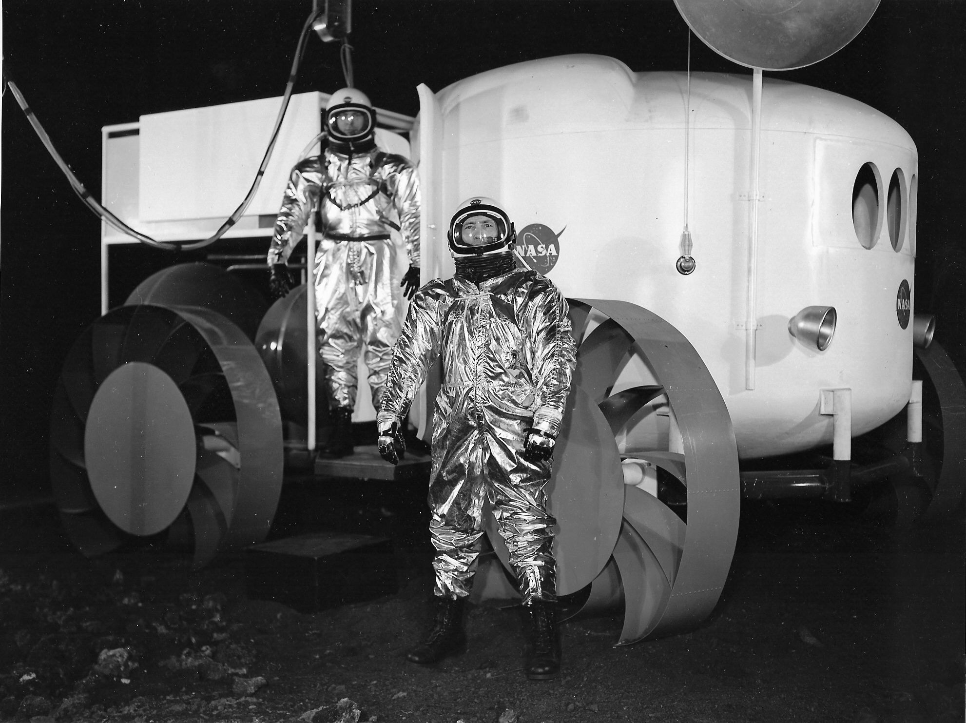
“A mobile laboratory on a lunar excursion is depicted in this artist’s drawing. The wheeled vehicle is being studied as a way of transporting men and equipment several miles from the lunar excursion module, shown at left, or other proposed lunar shelters. The NASA-Marshall Space Flight Center is directing the work being done on many lunar surface vehicles.”
Note the MOLAB landing module/descent stage immediately to the right of the vehicle. Also, the original title, possibly "MOLAB EXCURSION" was marked out. The LEM/astronaut scene is taken from that originally created by Craig Kavafes for Grumman.
A nearly identical variant, of which the artist is conclusively identified to be Rosemary A. Dobbins. Therefore reasonable to assume my posted photo is as well. So I’m going with it. A huge & unexpected WIN. At:
commons.m.wikimedia.org/wiki/File:Lander_Rover_Apollo_Mis...
Specifically:
upload.wikimedia.org/wikipedia/commons/b/b8/Lander_Rover_...
Credit: Wikimedia Commons
www.pinterest.com/pin/98727416805204212/
Credit: Pinterest/Enrico Brunoni
www.jmargolin.com/svr/refs/ref15_lunar_driving_history.pdf
Credit: Jed Margolin's website
BTW, Rosemary Dobbins’ daughter: YOU’RE WELCOME.
NASA Administrator Jim Bridenstine and Marshall Space Flight Center Director Jody Singer at the 11th Annual Wernher von Braun Symposium in Huntsville, Alabama.
Image Credit: NASA
More than 500 students from around the world competed in NASA's Human Exploration Rover Challenge (HERC) Friday, April 21, and Saturday, April 22, at the Aviation Challenge camp of the U.S. Space & Rocket Center, near NASA's Marshall Space Flight Center in Huntsville, Alabama.
NASA hosted 48 teams from 16 states, the District of Columbia and Puerto Rico, as well as the countries of Bolivia, Brazil, Colombia, Dominican Republic, India, Mexico, Peru, and Singapore.
Throughout the nine-month challenge, each team will attempt to design, build, and test human-powered rovers capable of traversing a challenging half-mile obstacle course that simulates the terrain of the Moon, Mars, or other rocky bodies in our solar system. In addition, students must also design and demonstrate a unique tool capable of completing various mission tasks.
HERC is one of NASA's nine Artemis Student Challenges - a variety of activities providing students access to the knowledge and technology required to achieve the goals of the Artemis Program.
Replays of the competition are available on NASA Marshall YouTube and NASA's HERC Facebook page.
IMAGE CREDIT: NASA
Built for the MSFC contest on EB. This MOC is supposed to be a Sci-fi hotel in a luxurious city. I've been wanting to use the technique that gives the building it's curve for a while now, but didn't have any idea what to use it for, until now. It uses 1x4 hinge plates and 1x2 bricks with studs on the sides to achieve this effect. I may post a breakdown shot latter.
“Molab has large wheels with spokes designed to double back as springs to absorb shock and eliminate skipping on the low gravity surface. On the front of the round cockpit are a two-way radio antenna and a dish antenna.”
Something I wasn't aware of...note the test subject egressing the vehicle. Apparently, the MOLAB cabin/cockpit was pressurized, providing a stuffed-shirtsleeve environment.
I think you need to be over 45 to get that...maybe 50. That looks like it might be Robert Young. Definitely need to be over 50 for that one.
"KLAATU BARADA NIKTO":
Credit: "Skeet Vaughan's web site" website
Rhetorical question, but, where are all of these wonderful relics? I’m sure all of the buy-outs, mergers, etc. hastened their being lost to time, especially those that never came to fruition for whatever reason, especially if a/the “the losing entry”. I understand, but sad nonetheless, to me.
A brief view of the vehicle in color, along with other good stuff:
Credit: NASA’s Marshall Space Flight Center/YouTube
"SATURN ENGINE APPLICATIONS"
Per the official description associated with MSFC-9801767 (see comments & thanks to Cygni_18):
"This image illustrates the basic differences between the three Saturn launch vehicles developed by the Marshall Space Flight Center. The Saturn I, consisted of two stages, the S-I (eight H-1 engines) and the S-IV (six RL-10 engines). The Saturn IB (center) also consisted of two stages, the S-IB (eight H-1 engines) and the S-IVB (one J-2 engine). The Saturn V consisted of three stages, the S-IC (five F-1 engines), the S-II (five J-2 engines), and the S-IVB (one J-2 engine)."
"IND A1404E" is an unfamiliar photo ID, I've never seen anything resembling it.
MSFC astronomer Bill Cooke took this five-minute exposure of Comet Hartley 2 late on the night of Saturday, Oct. 16, 2010, using a 10" telescope in New Mexico.
The comet, which has now reached naked eye visibility, was just under 11.5 million miles from Earth and sporting a coma over a degree across -- twice the size of the full moon. You can read more about the "coma" and other parts of a comet at the NASA Worldbook: Comets page.
This very active visitor to our neighborhood makes its closest approach around 8 a.m. EDT on Oct. 20, at a distance of 11.2 million miles. Unfortunately, the light from the nearly full moon will tend to wash out the comet's pale green glow, so comet watchers are advised to make use of a pair of binoculars for the best view.
Image courtesy of Bill Cooke, NASA's Meteoroid Environment Office, Marshall Space Flight Center, Huntsville, Ala.
More than 500 students from around the world competed in NASA's Human Exploration Rover Challenge (HERC) Friday, April 21, and Saturday, April 22, at the Aviation Challenge camp of the U.S. Space & Rocket Center, near NASA's Marshall Space Flight Center in Huntsville, Alabama.
NASA hosted 48 teams from 16 states, the District of Columbia and Puerto Rico, as well as the countries of Bolivia, Brazil, Colombia, Dominican Republic, India, Mexico, Peru, and Singapore.
Throughout the nine-month challenge, each team will attempt to design, build, and test human-powered rovers capable of traversing a challenging half-mile obstacle course that simulates the terrain of the Moon, Mars, or other rocky bodies in our solar system. In addition, students must also design and demonstrate a unique tool capable of completing various mission tasks.
HERC is one of NASA's nine Artemis Student Challenges - a variety of activities providing students access to the knowledge and technology required to achieve the goals of the Artemis Program.
Replays of the competition are available on NASA Marshall YouTube and NASA's HERC Facebook page.
IMAGE CREDIT: NASA
A test article of the stage adapter aced structural loads testing at the Marshall Center's East Test Area. (NASA/MSFC)
More about SLS:
More SLS graphics and concepts:
www.nasa.gov/exploration/systems/sls/multimedia/gallery/S...
Space Launch System Flickr album
www.flickr.com/photos/28634332@N05/sets/72157627559536895/
________________________________
These official NASA photographs are being made available for publication by news organizations and/or for personal use printing by the subject(s) of the photographs. The photographs may not be used in materials, advertisements, products, or promotions that in any way suggest approval or endorsement by NASA. All Images used must be credited. For information on usage rights please visit: www.nasa.gov/audience/formedia/features/MP_Photo_Guidelin...