View allAll Photos Tagged breadboard
A 21st century interpretation of William Penn’s “greene country towne” will appear atop the PECO Crown Lights as the first Art in the Air exhibit of 2011 opens Friday, Sept. 2.
"The Green and Growing City" was created by Timothy Wingert specifically for the PECO Crown Lights as an animation reflecting both the life and energy of the city as well as Philadelphia's leading role in making urban areas "green" and artistically integrated into their natural surroundings. This 30-second animation of nature's growth and life cycles seen on top of one of the city's prominent structures represents what William Penn's idea of a “greene country towne” is all about.
Wingert’s work will be shown alongside “Dancers” by James Simpson and “Cool Waves” by Chris McManus. All three pieces will be displayed on the Crown Lights each Friday in September from 7 p.m. to midnight.
Art in the Air is a partnership between Breadboard, a program of the University City Science Center that explores the intersection of art, science and technology, and PECO. The September artworks were selected by Breadboard and PECO.
New exhibits will be mounted in October, November and December. In January, PECO and Breadboard will select the “Best in Show” works, selecting up to three pieces featured during the four, month-long exhibits for a chance to receive a $1,000 prize from Breadboard.
“Art in the Air” was launched in 2010 during Philadelphia’s annual Welcome America Celebration, commemorating the first anniversary of the launch of PECO’s new energy efficient LED Crown Lights system. In 2010, PECO featured the works of more than 20 different artists atop the lights as part of the program.
Artists interested in submitting their work for consideration should click here or submit their work to artintheair(at)sciencecenter(dot)org. More information about the PECO Crown Lights is available at www.peco.com/crownlights.
About Breadboard:
Breadboard is a program of the University City Science Center that explores intersections between contemporary art, design, science and technology. Expanding on 30-plus years of Esther Klein Gallery programming, Breadboard's mission is to convene communities around creative applications of technology. Breadboard also manages the Esther Klein Gallery (now known as EKG) at 3600 Market Street.
Here’s my Raspberry Pi talking to my GPS module. It was very simple to wire and connect and the LVTTL pins of the GPS were well suited to the Pis GPIO pins. The only hurdle I needed to jump was learning to disable kernel and serial logging and then learning how to access the serial device. There was several decent tutorials online as my knowledge of Linux is almost non-existent.
I used other tutorials which used USB GPSs to install gpsd (a GPS daemon). I ran cgps and xgps and only needed to alter the device they accessed to use them.
It was a fun fast task but I’m not going to get a fix with this GPS in its current location. I’ve yet to work out anything portable.
Breadboard for triggering flash with arduino
Image taken for Lesson 6: Trigger your flash with an Arduino of my highspeed photography 101
Bild fuer Lektion 6: Blitz mit einem Arduino auslösen meines 1x1 der Highspeed Fotografie
MOT coils are switched on and off frequently and quickly. The inductive kicks that result from switching 120A on and off are pretty violent. So, we've mounted the coils in a 316LN stainless steel collar a few mm above the vacuum system viewports.
The collar is rigidly connected to the chamber by these lead-shot-filled posts I made. The post walls are very thin, maybe 0.3 mm, so the bulk of the material is lead. A threaded stud links the post to the chamber, and a threaded flange nut was soldered on the top for mating with the collar.
All I know about vibration isolation is: alternate layers of rigid and squishy (in school, I minored in Impedance Mismatch). So, a rubber o-ring is jammed in between the lead-filled post and the collar clip. A strip of viton is wrapped around the copper coil and is compressed into the steel collar.
..but it might be someday. I haven't given up on building the ruby laser but I won't spend too much more time on it.
Today I was messing around with the alignment on my plywood breadboard and I realized that the alignment of the two mirrors was drifting rapidly (over a few minutes). That just won't work for a laser. Strangely enough it wasn't until today that I remembered an old optical breadboard that a friend gave me many years ago.
I've had it around and tried to use it on other optical projects but it never worked out. But it looks perfect for this application.
This shows the two mirrors and the ruby rod being illuminated by a Helium-Neon laser. the laser allows alignment of the mirrors. When things are close the beam flickers in an interesting way.
The picture was taken by setting off a small smoke bomb in the garage. The smoke scatters the light from the laser, otherwise only the ruby rod and small dots on the mirrors are visible.
Went on a hike today with Kathy, Ian and Monte. We had to change our plans because of a huge sports event that had the Pacific Coast Highway looking like downtown LA street parking. Went up the Chumash Trail, around the hill, into La Jolla Canyons and up and over down to the PCH.
Cheers.
Setup for testing some 4-pin square LEDS (aka super flux or piranha LEDs) on a breadboard.
For more info on my testing and thoughts on these LEDs, see my blog post: www.lungstruck.com/projects/superflux-piranha-led-testing/
We've created an easy to assemble Breadboard Based Arduino Compatible (BBAC) Micro-controller product,
For all the details visit our blog:
oomlout.com/blog/2009/04/breadboard_based_arduino_compa_1...
This is an laser cut enclosure for mobile arduino prototyping. I will start selling this soon. A bit more testing is needed.
Check:
RAM wiring finished, BNC connector for clock input, and a little breadboard (mostly for hooking things up to SPI)
Little electronics project I'm working on. Personally, I'm not entirely sure where it's going. I thought it would be neat to make a box with a USB interface to a 3-axis accelerometer and a 3-axis magnetometer.
Just trying to find an easier way to manage the connectors for the Arduino board so time to use a breadboard rather than mess about with lots of soldering.
We built an Arduino-powered Drawbot!
See the blog post for full details: rasterweb.net/raster/2011/01/12/friday-night-drawbot/
When you're building circuits on a breadboard there is nothing more annoying than having to measure, snip, and then strip both ends of each and every piece of wire.
Well perhaps there are greater annoyances but that does not mean that this problem should go un-addressed. Addressed it has become, and if you too have a few stepper motors, a hand-held wire stripper and a bunch of nuts and bolts your life, too, can become easier.
For all of you crying overkill, we do have a small ulterior motive, at oomlout.com we manufacture a number of kits that come with pre-stripped wires hence the need for semi automation. This version is the much improved brethren of version one.
If you'd like to build your own full details can be found here:
A video of it in action;
www.youtube.com/watch?v=fftZq_deIls
A second video (a little shaky but better at showing the different components)
The Limrose Electronics digital logic tutor or breadboard. The design is from 1972, but this model was made in about 1982 (by the date codes on the power supply). Top left is a switchable 2Hz or 18kHz clock, built not with a chip but with discrete transistors. Below that is a bank of logic state switches (not debounced). On the right-hand side is a row of red LEDs for us as logic level indicators -- each one has a driver transistor (BC182). Each 16-pin socket has two rows of pins or interconnections, plus some power pins. There's a 5V power supply inside.
I was somewhat disappointed with this “Bread Board Power Supply Shield (5V/3.3V compatible)” (Product 18/37) from Iteadstudio. When used switched to 5V it was only outputting 4.65V without any significant load. This is around 7% off (the 3.3V output was 3.29V much more respectable).
Being annoyed I investigated and I tried a few things (higher input voltage, removing all loads and checking for PCB faults) and eventually checked the AMS1117-5.0 voltage regulator and stuck my meter on it. I noticed it was outputting 4.99V so the voltage drop was somewhere on the board. Then I found a small diode inline on the output. The ~0.3V drop was caused by the diode; I could measure this, but what was the diode doing on the output of a voltage regulator?
I believe this diode should have been attached to Vin as the datasheet on page 4 (www.advanced-monolithic.com/pdf/ds1117.pdf). I’ve completed an online email form with Iteadstudio to inform them and we will see what happens.
The Teensy is a breadboard-friendly development board with loads of features in a, well, teensy package. The Teensy++ breaks out all of the IO available on the AT90USB1286 to breadboard-friendly 0.1" spaced headers so you can hook up a load of peripherals.
The Teensy++ comes pre-flashed with a bootloader so you can program it using the on-board USB connection: No external programmer needed! You can program the Teensy in your favorite IDE using C or you can install the Teensyduino add-on for the Arduino IDE and write Arduino sketches for Teensy!
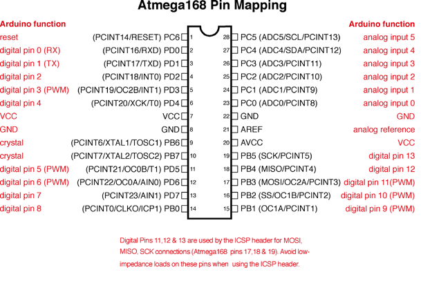
Breadboard + Atmega328. Detalhes sobre a pinagem do Atmega: arduino.cc/en/uploads/Hacking/Atmega168PinMap2.png
As I was fixing my lunch, I was struck by the way the light came through the window and hit the lettuce. So I pulled out my trusty iPhone and took this one.
I used Mobil Manet to make a sketch that I blended with the original using Iris Photo Suite. I also blended several photos that I had taken for my textures file and applied them. (In all of these moves, I used blend modes and reduced opacity.) Finally, I took the image into Photo Forge where I applied the Oil Painting filter (at a reduced opacity).
My general intent with all of this was to increase the tactile texture of the lettuce and to warm up the image.
It works!
When the voltage coming off the solar cell is high, the battery will charge. When the voltage falls below a threshold, the leftmost transistor will turn off which turns on the second half of the circuit. This amplifies the voltage from the battery (AAA) enough to turn on the LED.
Circuit diagram and thorough explanation: www.talkingelectronics.com.au/projects/SolarLight/SolarLi...
This is my first breadboard project for over ten years. It wasn’t as straightforward as I had hoped it would be.
For starters I think the ATmega328P was not programmed with an Arduino Bootloader, or the fuses were set incorrectly. Having said that I have to give the seller (Iteadstudio) the benefit of the doubt because there’s a chance I simply messed something up.
I followed these instructions itp.nyu.edu/physcomp/Tutorials/ArduinoBreadboard which I found good but they didn’t cover manually setting the fuses- something I had to do because I was using the AVRISP mkII and AVR Studio 4 to program the bootloader.
Getting the bootloader on required lowering my clock speed to 500kHz (after blaming my wiring several times) and then the blinking on reset showed I was running at a much slower clock rate. That lead me to correct the fuses so the ATMega328P would use the external 16Mhz crystal. All worked as it should and it was a good learning experience connecting and using a ATMega328P from scratch.
After changing the drivers for the AVRISP I can use it in the Arduino IDE and use “File -> Upload Using Programmer” completely bypassing the need for a bootloader.
Vintage 1920s decorative French oak breadboard souvenir from Lourdes. The pochoir by Albray shows the Sanctuary of our Lady of Lourdes.
#indiastreetantiques
Grumble, this is why you should always buy the damn adapter. Just because you *can* breadboard it doesn't mean its worth your time...
Here, several laser beams meet to slow, capture, cool, and confine a ytterbium atomic vapor. In 100ms, we expect to be able to cool about 10-100 thousand atoms to 10µK and to load them into an optical lattice trap. Ultrastable "clock" laser light also enters through these windows.
Update: first results for this optical lattice clock.
We've created an easy to assemble Breadboard Based Arduino Compatible (BBAC) Micro-controller product,
For all the details visit our blog:
oomlout.com/blog/2009/04/breadboard_based_arduino_compa_1...
Arduino Nano witth HTU21D humidity and temperature sensor, and a ILI9163 LCD.
The LCD is connected to Arduino, through a voltage level conversion home-made board, that lays under the LCD, and that's why it not shows on the picture.
We've created an easy to assemble Breadboard Based Arduino Compatible (BBAC) Micro-controller product,
For all the details visit our blog:
oomlout.com/blog/2009/04/breadboard_based_arduino_compa_1...