View allAll Photos Tagged Modellbau
More new pics from an old model, built many moons ago...
Inspired by the tables from "This is animation, Special: MACROSS PLUS), this is a VF-1J in a design variant that sticks close to early Sukhoij SU-27 fighters (hence the red star as a squadron marking). I would not call it authentic for the Macross universe - but since other real paint schemes appear in official VF-1 publications, it's plausible. And it looks quite pretty, too. ^^
Not having authentic Russian air force colors at hand, the camouflage scheme was improvised with Humbrol enamels: Upper surfaces in 65 (Aircraft Blue/RLM65/FS 35526), 89 (Middle Blue) and 140 (Dark Gull Grey, FS 36231), and 122 (Israeli Light Blue, FS:35622) underneath, with some mild weathering. Works quite well, esp. on the small model.
The "kite" roundels were printed at home and semi-disappeared under thinned paint as low-viz markings, more promimentbecame the Red Stars on the fins and the large Soviet-style tactical code.
Added details include antennae, a new cockpit with a pilot, new missiles (actually 1:72 Red Top AAMs from an Airfix BAC Lightning kit and some Russian AA-1, probably from an Academy MiG-23) and scratched ECM/chaff dispenser pods.
+++ DISCLAIMER +++
Nothing you see here is real, even though the conversion or the presented background story might be based on historical facts. BEWARE!
Some background:
The 80th Pursuit Group (Interceptor) was constituted on 13 January 1942 and activated on February 1942. It was redesignated as the 80th Fighter Group in May 1942. During World War II, the group was the first USAAF unit to be stationed in Burma after the Allied retreat in 1942. During its two years in combat, this group, which called itself the Burma Banshees, kept the supply lines open to China while clearing the way for Allied forces and US Army units such as Merrill's Marauders to sweep Japanese forces from northern Burma.
The 80th trained for combat and served as part of the defense force for the northeastern United States from, 1942–1943. Its flying squadrons were the 88th, 89th, and 90th Pursuit (later Fighter) Squadrons, later augmented by the 459th Fighter Squadron.
The 80th sailed for India, via Brazil, the Cape of Good Hope, and Ceylon, in May 1943, commencing combat operations in the China-Burma-India theater in September 1943. The group supported Allied ground forces during the battle for northern Burma and the push southward to Rangoon, bombing and strafing troop concentrations, supply dumps, lines of communication, artillery positions, and other objectives.
Initial flying material consisted mainly of the P-40 and a few P-38 fighters. Using modified, so-called “B-40 fighter” bombers (P-40s fitted with a single 1,000-pound bomb), the 80th FG attacked Japanese-held bridges, sometimes demolishing their target with a single bomb. The 80th was assigned the defense of the Indian terminus of the Hump route, which it carried out by striking Japanese airfields and patrolling Allied air bases to safeguard them from attack. The 80th received a Distinguished Unit Citation for intercepting a formation of Japanese aircraft, preventing the destruction of a large oil refinery in Assam, India, on 27 March 1944. During this engagement, they shot down 18 enemy machines without losing any of their own.
After the capture of Myitkyina and the nearby airfield on May 17, 1944, parts of the 80th Fighter Group relocated to this location. During the heavy fighting around Kohima and Imphal, the British troops deployed there requested air support and the 80th Fighter Group was able to successfully thwart the Japanese advance. In the further course of the operations in Burma, the pilots of the 80th Fighter Group destroyed more than 200 bridges held by the Japanese and shot down around 80 Japanese planes.
Though its primary mission in Burma was the protection of the "Hump" cargo route, the group also played an important role in reopening the Ledo/Burma Road.
From mid-1944 onwards, the P-40s were supplemented and gradually replaced with the new, much more potent P-47 Thunderbolt. With their heavier machine gun armament (eight instead of six 0.5” machine guns) and a much higher ordnance load of up to 2,500 lb (1,100 kg) of bombs, unguided rockets and M10 “Bazooka” launchers, this new aircraft type proved to be very effective.
The Republic P-47 Thunderbolt was a World War II-era fighter aircraft produced by the American aerospace company Republic Aviation from 1941 through 1945. When fully loaded, the P-47 weighed up to eight tons, making it one of the heaviest fighters of the war. The Thunderbolt was effective as a short-to medium-range escort fighter in high-altitude air-to-air combat and ground attack in both the European and Pacific theaters. The P-47 was designed around the powerful Pratt & Whitney R-2800 Double Wasp 18-cylinder radial engine, which also powered two U.S. Navy/U.S. Marine Corps fighters, the Grumman F6F Hellcat and the Vought F4U Corsair. The P-47 became one of the main United States Army Air Forces (USAAF) fighters of World War II and also served with other Allied air forces, including those of France, the United Kingdom, and the Soviet Union. Mexican and Brazilian squadrons fighting alongside the USAAF also flew the P-47. The Thunderbolt’s armored cockpit was relatively roomy and comfortable. Nicknamed the "Jug" owing to its appearance if stood on its nose, the P-47 was noted for its firepower, as well as its ability to resist battle damage and remain airworthy.
From October 1944 the operations of the 80th Fighter Group in Northern Burma concentrated on the destruction of the routes of the Burma Railway. Operations with army support (operating as "cab ranks" to be called in when needed) were very successful, with attacks on enemy airfields and lines of communication, and the aircraft flew a number escort sorties. An 80th FG squadron could finally be relocated to Shingbwiyang and was thus in the immediate vicinity of Ledo Street, which was under construction. The squadron flew many sorties against advancing Japanese forces and was instrumental in the capture of Myitkyina. Napalm bombs, a new weapon and initially improvised from drop tanks with makeshift fins, were also used with devastating effect, but some of them very close to the company's own lines.
By the end of the war, the group had destroyed more than 200 bridges and killed scores of bridge repair crews. Air-to-air and air-to-ground sweeps by the group's pilots claimed 80 enemy planes destroyed in the air or on the ground. The 80th Fighter Group was withdrawn from combat in May 1945 and inactivated in November.
General characteristics:
Crew: 1
Length: 36 ft 1.75 in (11.02 m)
Wingspan: 40 ft 9 5/16 in (12.429 m)
Height: 14 ft 8 1/16 in (4.472 m)
Airfoil: Seversky S-3
Empty weight: 10,000 lb (4,536 kg)
Max takeoff weight: 17,500 lb (7,938 kg)
Powerplant:
1 × Pratt & Whitney R-2800-59 18-cylinder air-cooled radial piston engine, 2,000 hp (1,500 kW),
driving a 4-bladed Curtiss Electric C542S constant-speed propeller, 13 ft (4.0 m) diameter
Performance:
Maximum speed: 426 mph (686 km/h, 370 kn) at 30,000 ft (9,100 m)
Range: 1,030 mi (1,660 km, 900 nmi)
Service ceiling: 42,000 ft (13,000 m)
Armament:
8x 0.5” caliber (12.7 mm) M2 Browning machine guns (3.400 rounds)
Up to 2,500 lb (1,100 kg) of bombs, drop tanks and/or up to ten 5” (130 mm) unguided rockets
The kit and its assembly:
This is a very modest what-if model – just a fictional livery on a stock model, and part of the ongoing plan to “build down” The Stash™ of kits during the ongoing Corona lockdown. The idea behind it was spawned by a number of decals for P-40s for the 80th FG I found in my scrap box, which all carried spectacular skull markings on their noses. I wondered if and how these could be adapted to another aircraft type – and the P-47 lent itself for this project due to its sheer “canvas” size, despite having a radial engine, and being the natural successor of the P-40 in USAAF service.
From that I spun the idea further and settled for an early Razorback P-47D, in the form of the very nice Academy kit. The kit was basically built OOB, it went together nicely without major fights – a trait that I really like about most Academy kits. The only true weak spot of the P-47 is the flaps’ undersides: they are pretty thick/massive, so that there are shallow sinkholes. These are easy to fill, though, even though I ignored this flaw and rather lowered the flaps, a mod that’s pretty easy to do.
An addition is a scratched D/F loop antenna on a streamlined socket behind the cockpit, a typical feature of P-47s operated in the BMI theatre. The loop was created with thin wire, the socket is a piece of sprue, integrated into the spine with some putty. As a late-production Razorback Thunderbolt I gave the aircraft a Curtiss Electric paddle-bladed propeller, which the Academy kit offers as an optional piece.
The ordnance was also taken from the kit: a pair of Bazooka triple launchers for ground attack duties and a drop tank under the fuselage.
Painting and markings:
A simple affair: as an early P-47, I gave the aircraft the standard USAAF livery of olive drab and neutral grey. I used Tamiya XF-62, IMHO the best interpretation of the tone, and ModelMaster 1740, actually FS 36231 instead of FS 36173, but the Dark Gull Grey is a bit lighter than Neutral Grey and looks IMHO better on the 1:72 scale model. AFAIK, no P-47 carried the earlier mid-green blotches on the wings anymore. The cockpit was painted in Interior Green, while the landing gear wells became zinc chromate yellow, very traditional.
The individual aircraft markings were more spectacular and also challenging. The real eye-catcher is pair of 80th FG skulls on the cowling flanks, even though these had to be completed with paint since they come from a Hobby Boss P-40N and feature empty sections for the exhaust stubs. The empty eye sockets had to be added manually, too, and since there was now a lot of white, I added – after consulting pictures of 80th FG P-40s - thin black lines to the skull with a felt tip pen. A real improvement, and it’s even authentic!
Furthermore, I added 1st Air Commando Group markings in the form of five white diagonal stripes around the rear fuselage. This group operated in the BMI area, e.g. P-51s, B-25s and even P-47s, but the 80th FG was not part of it. Nevertheless, the stripes suit the Razorback very well, and they were created with generic 2mm decal stripes from TL Modellbau. Each stripe had to be applied and trimmed individually, not an easy task on the conical tail with its concave and convex surface. The result is not perfect, but I am fine with it, and it looks very cool.
Pictures of early USAAF P-47s in the BMI are hard to find, but what I found suggests that Allied machines wore single bands on wings and tail surfaces as additional ID markings from 1943 on, much like the P-47s over Europe. On later NMF aircraft, these were dark blue (on both USAAF and RAF aircraft), and I was lucky to have a complete set of white P-47 markings left over from an Xtradecal set for SEAC RAF Thunderbolts, which comes with pre-cut bands in white and blue, very convenient! On the downside, the white fuselage stripes dramatically revealed that the P-47’s OOB decals, esp. the Stars and Bars, lacked opacity, so that I had to add some white paint manually to hide the resulting mess.
Typical unit markings of the 89th FS are a red spinner, and since the P-47 has only a small one, I added a thin red frame around the cowling, as carried by later real-world 89th FS P-47s, which were left in bare metal, though. As a gimmick I painted the wheel hubs in red, too. As a personal marking of the pilot I christened the aircraft “The Big Fella”, taken from an Irish pre-WWII armored car, and I added some air victory markings.
As usual, the kit received a black ink washing overall and some post panel shading with Revell 42 and 46 on the upper surfaces and ModelMaster 2105 (Dark French Blue Gray) underneath for visual drama and weathering. Some light soot stains around the gun muzzled were created with graphite, oil stains under the fuselage with Tamiya “Smoke”.
While this was not a complex build and even the livery is pretty close to real world standards, I like the outcome and how the skull markings stand out on the huge P-47. The array of fuselage stripes are an interesting visual extra, even though I was afraid that they were, together with the white ID stripes on the wings, a bit too much. The red highlights are an interesting contrast, too, and IMHO the whole decoration works fine. Everything fictional, but plausible and believable.
Haben Sie Interesse an Modellbau ,Militär-Modelle , dann sehen Sie folgende Webseite an :
Êtes-vous intéressé à la modélisation militaire, alors s'il vous plaît consulter le site Web suivant pour:
A Little Support for my French Friends / Mit freundlicher Unterstützung
Are you interested in military modeling, then please see the following web page:
+++ DISCLAIMER +++
Nothing you see here is real, even though the conversion or the presented background story might be based on historical facts. BEWARE!
The Supermarine Spitfire was a British single-seat fighter aircraft used by the Royal Air Force and other Allied countries before, during and after World War II. Many variants of the Spitfire were built, using several wing configurations, and it was produced in greater numbers than any other British aircraft. It was also the only British fighter produced continuously throughout the war.
The Spitfire was designed as a short-range, high-performance interceptor aircraft by R. J. Mitchell, chief designer at Supermarine Aviation Works, which operated as a subsidiary of Vickers-Armstrong from 1928. Mitchell pushed the Spitfire's distinctive elliptical wing designed by Beverley Shenstone to have the thinnest possible cross-section, helping give the aircraft a higher top speed than several contemporary fighters, including the Hawker Hurricane. Mitchell continued to refine the design until his death in 1937, whereupon his colleague Joseph Smith took over as chief designer, overseeing the Spitfire's development through its multitude of variants and many sub-variants. These covered the Spitfire in development from the Merlin to Griffon water-cooled inline engines, the high-speed photo-reconnaissance variants and the different wing configurations.
One exception was the Spitfire Mk. X: it was the only variant powered by a radial engine, and it looked quite different from its sleek Merlin-powered brethren. Early in its development, the Merlin engine's lack of fuel injection meant that Spitfires and Hurricanes, unlike the Bf 109E, were unable to simply nose down into a steep dive. This meant a Luftwaffe fighter could simply "bunt" into a high-power dive to escape an attack, leaving the Spitfire behind, as its fuel was forced out of the carburetor by negative "g". An alternative engine was to solve this issue. Another factor that suggested an air-cooled engine were theatres of operations in the Far East, primarily India: the hot and humid climate was expected to be a severe operational problem for the liquid-cooled Merlin. As a further side effect a radial engine was expected to be easier to maintain under these conditions than the Merlin.
The project of a radial-powered Spitfire variant was eventually launched in late 1940. The choice for the power unit fell on a Bristol Taurus II 14-Cylinder engine, which had an appreciable small diameter, was available in ample numbers and had about the same power output as the early Merlin variants used in the Spitfire Mk. I and II (1.030 hp/740kW). In order to save time and keep the radial engine variant as close as possible to the Spitfire V design, the production type of that era. The new type’s structure and fuselage were only adapted to a minimum to allow the bulkier power unit and its periphery to be taken. The fuselage was widened in front of the cockpit section, a new engine mount was integrated and the Merlin’s radiator bath and respective piping were removed. The oil cooler under the port wing was retained, though, and the Taurus engine was from the start outfitted with dust filters, so that all resulting Spitfire Mk. Xs left the factory tropicalized. Like the Spitfire Mk. V, different wing armaments were available, e.g. an “A” wing with eight .303 in machine guns and a “B” wing with two 20 mm cannon and four machine guns.
The first Spitfire Mk. Xs, finally outfitted with a more powerful Taurus VI engine, were delivered to homeland RAF units for evaluation from May 1941 onwards. From the start, the radial-powered Spitfire proved to be inferior to the Merlin-powered variants - even to the early Mk. Is – and they were no match to the modern German fighters, especially at high altitude. As a consequence many Mk. Xs received clipped wing tips for better roll characteristics at low altitude (receiving an additional “L.F.” designation), but this did not significantly improve the type’s overall mediocre performance. Only a few Mk. Xs were actually employed by front line units, most were quickly relegated to training units. Later production aircraft were immediately shipped to the Far East or to units in Northern Africa, where they could be used more effectively.
A few machines were also delivered to Egypt (30), the Netherlands (12 for the East Indies NL-KNIL, which eventually ended up in RAAF service) and Turkey (24). In 1942, many machines still based in Great Britain were handed over to the USAAF, being either used for USAAF pilot and conversion training, or they were allocated to the Northern Africa invasion force during Operation Torch.
Since the Taurus-powered Spitfire turned out to be quite ineffective (it was no good either in the fighter or in an alternative ground attack role and 20 mph slower than the comparable Mk. V), production was already stopped in late 1942 after 353 aircraft. At the same time, the Spitfire Mk. IX with a much more powerful Merlin engine entered service, and all resources were immediately allocated to this more potent fighter variant and the idea of the Spitfire with a radial engine was ultimately dropped. Since the Taurus-powered type was quickly phased out of frontline service, the designation was later re-used for a pressurized high-altitude photo reconnaissance variant of the Spitfire, the PR.X, of which only 16 machines were built.
General characteristics:
Crew: one pilot
Length: 29 ft 6 in (9.00 m)
Wingspan: 32 ft 2 in (9.80 m)
Height: 11 ft 5 in (3.86 m)
Wing area: 242.1 ft2 (22.48 m²)
Airfoil: NACA 2213 (root)
NACA 2209.4 (tip)
Empty weight: 5,065 lb (2,297 kg)
Loaded weight: 6,622 lb (3,000 kg)
Max. takeoff weight: 6,700 lb (3,039 kg)
Powerplant:
1× Bristol Taurus VI 14-Cylinder sleeve valve radial engine, 1.130 hp (830 kW)
Performance:
Maximum speed: 350 mph (312 kn, 565 km/h)
Combat radius: 410 nmi (470 mi/756 km)
Ferry range: 991 nmi (1,135 mi/1,827 km)
Service ceiling: 36,500 ft (11,125 m)
Rate of climb: 2,535 ft/min (12.9 m/s)
Wing loading: 27.35 lb/ft2 (133.5 kg/m²)
Power/mass: 0.22 hp/lb (0.36 kW/kg)
Armament:
2× 20 mm Hispano Mk II with 60 RPG
4× .303 in Browning Mk II machine guns with 350 RPG
The kit and its assembly:
My third contribution to the “RAF Centenary” Group Build at whatifmodelers.com, and the next one in chronological order. This one was spawned by the simple thought of “What would a Spitfire with a radial engine look like…?”. I have seen this stunt done in the form of a Fw190/Spitfire kitbash – nice result, but it did IMHO just not look like a “real” Spitfire with a radial engine, rather like an Fw 190 with elliptical wings. And the fact that I had already successfully transplanted a Centaurus engine onto a P-51 airframe made me feel positive that the stunt could be done!
Consequently, the conversion was pretty straightforward. The basis is a Revell 1:72 Spitfire VB (1996 mold), which was – except for the nose section – taken OOB. A simple, nice kit, even though it comes with some flaws, like a depression at the rear of the wing/fuselage intersection and the general need for PSR – not much, but I expected a better fit for such a relatively young mold?
For the engine, I used a personal replacement favorite, the cowling and the engine block from a Mitsubishi A6M2 “Zero” (Hasegawa). The Nakajima Sakae radial engine has a relatively small diameter, so that it serves well as a dummy for the compact Bristol Taurus engine – a replacement I have already used for a radial-powered Westland Whirlwind. The other benefit of the small diameter is that it is relatively easy to blend the round front end into the oval and very slender fuselage of the early Spitfire airframe. This was realized through massive body sculpting from scratch with 2C putty, widening the area in front of the cockpit and expanding its width to match the cowling – I guess that real life engineers would have followed a similar, simple path.
Since the radial engine would not need a radiator, I simple omitted this piece (cut out from the single piece lower wing half) and faired the respective underwing area over with a piece of styrene sheet and PSR. The asymmetrical oil cooler was retained, though. The propeller is a replacement from the scrap box, with a smaller diameter spinner and more slender blades which better suit the open cowling.
Since the Taurus had its best performance at low altitudes, I used the Revell kit’s OOB option of clipped wing tips – a move that makes the aircraft look much faster, esp. with the new, deeper nose section.
Painting and markings:
I did not want classic RAF markings, but still keep the model well within the Centenary GB confines. The original plan had been a classic Dark Green/Ocean Grey livery, which all Spitfire’s in USAAF service and based in the UK received. But I rather wanted to create a frontline aircraft, operated during Operation Torch in late 1942/early 1943 with American roundels – and the grey/green look would not look plausible on a machine taking part in the North African campaign. In fact, any Spitfire with American roundels I found that was used in North Africa carried the RAF Tropical Scheme in Dark Earth/Middle Stone. And, AFAIK, during Operation 'Torch' all British aircraft received American markings in the hope that the Vichy French, who were anti-British due to them bombing their ships in 1940, would switch to the allied cause. They were supposed to think that the Americans would be invading, not British troops as well. So I eventually switched to the classic Tropical Scheme (using Humbrol 29 and Modelmaster 2052 as basic tones), and it does not look bad at all - even though the yellow trim around the roundels does not stand out as much as on a Grey/Green aircraft.
Typically, the RAF codes were retained, as well as – at least during the early phases of Operation Torch – the RAF fin flash. A little personal twist is the pale blue (Humbrol 23, Duck Egg Blue) underside of the aircraft, instead of the typical Azure Blue. The rationale behind is that the Tropical Scheme was originally designed with Sky undersides, and the blue shades were later modifications after initial field experience.
The red spinner is a typical Northern Africa marking, and found on many 5th FS aircraft.
The interior (cockpit, landing gear wells) was painted with RAF Cockpit Green (Modelmaster), while wheels and struts became light grey.
As a standard procedure, the kit received a light black ink wash and a post shading treatment.
The decals were puzzled together from various sheets and sources, the design benchmark was a real USAAF Spitfire Vb from Operation Torch, though. The code letters were taken from an Xtradecal sheet, the roundels come from a Carpena Spitfire sheet, even though I placed American markings in all six positions – the roundels without yellow trim under the wings were taken from a Hobby Boss F6F sheet.
The serial number comes from the Revell kit’s OOB sheet, because it fits perfectly into the kit’s intended time frame. The nose art comes from a P-38 sheet (PrintScale) – not a typical feature for an RAF Spitfire, but a frequent personal decoration among USAAF machines during Operation Torch (e.g. on P-40s).
The Allied yellow ID markings on the wings’ leading edges, which were typically carried by Operation Torch Spitfires, too, were created with generic yellow decal sheet (TL Modellbau), while the maroon machine gun nozzle covers are part of Revell’s OOB sheet.
Finally, the kit received some soot stains around gun and exhaust nozzles, and was finally sealed with matt acrylic varnish.
A bold experiment, and it turned out well. The Zero’s cowling has the perfect diameter for this transplant, and the scratch-sculpted new front fuselage section blends well with the new engine – the whole thing really looks intentional! I am just not certain if the resulting aircraft still deserves the “Spitfire” designation? Even though only the engine was changed, the aircraft looks really different and has a Ki-43ish aura? I guess that a dark green livery and some hinomaru would also look great and pretty plausible?
Modell gebaut von / model built by Ernst Eyle. More:
www.wolfgang-kynast.de/foto/dampf/index.html
All machines are fully functional!
+++ DISCLAIMER +++
Nothing you see here is real, even though the conversion or the presented background story might be based on historical facts. BEWARE!
Some background:
The Supermarine Jetfire was a stopgap solution in order to introduce a jet-powered interceptor agains German V-1 missiles that threatened the London region from June 1944 on. At that time, the only aircraft with the low-altitude speed to be effective against it was the Hawker Tempest, but fewer than 30 Tempests were available. They were assigned to No. 150 Wing RAF, and early attempts to intercept and destroy V-1s often failed.
One alternative was the jet-powered Gloster Meteor, which still was development - and in order to get the new engine into service (also as a response to Gloster's engagement for E.1/44 with the single-engine "Ace" fighter) Supermarine responded with the idea to replace the nose-mounted piston engine with a single Whittle W.2 engine: The "Jetfire" was born.
The conversion was rather simple: the Jetfire was actually a Griffon-powered Spitfire XIV with as few changes to the original airframe in order to accept the W.2. The aircraft's forward fuselage was widened to accommodate the bulbous engine with a simple nose intake. The deeper forward part of the fuselage with its round diameter gave the aircraft a pronounced "pod-and-boom" configuration.
Internally, the front wing spar had to be bent into an inverted U-shape to clear the engine and its jet pipe.
The W.2 was mounted slightly angled downwards, and the jet pipe was bifurcated so that it ran along the fuselage flanks above the wings, with an exhaust just behind the wings’ trailing edges. To protect the fuselage, steel heatshield were added to the flanks. Furthermore, the former radiator fairings for the Griffon and the respective plumbing were removed and faired over, saving weight and internal space – and weight was reduced as much as possible to achieve a decent performance with the rather experimental centrifugal jet engine. The conventional Spitfire tailsitter landing gear remained unmodified, just additional covers for the main wheels were added for improved aerodynamics at high speed.
The first prototype was already finished in October 1944, and taxiing trials started immediately. The heatshields proved to be too short and the heat from the engine exhaust melted the duralumin skin of the rear fuselage. Additionally, the tailwheel received a longer strut for a cleaner airflow under the stabilizer on the ground – the original, shorter strut created an air cushion under the stabilizer that lifted the whole tail upwards when the throttle was opened, resulting in poor handling at low taxiing speeds.
Modifications to rectify the problems took until late December, and by this time a second prototype had been completed. After a few taxiing tests, it was transferred to the Royal Aircraft Establishment (RAE) for full-scale wind tunnel testing that lasted until February 1945.
On the 26th of that month, the RAF issued requirements that the aircraft should have a maximum speed of 770 km/h (480 mph) at sea level and a speed of 850 km/h (530 mph) at an altitude of 5,000 meters (16,400 ft). It should be able to climb to that altitude in 4 1/2 minutes or less and it should have a range of 500 kilometers (310 mi) at 90% of maximum speed.
The Jetfire failed to meet these targets, but it was still fast enough to intercept the V-1 and was quickly available. The average speed of V-1s was 550 km/h (340 mph) and their average altitude was 1,000 m (3,300 ft) to 1,200 m (3,900 ft). Fighter aircraft required excellent low altitude performance to intercept them and enough firepower to ensure that they were destroyed in the air rather than crashing to earth and detonating. Most aircraft were too slow to catch a V-1 unless they had a height advantage, allowing them to gain speed by diving on their target.
Originally a total of 200 Jetfire Mk.Is were ordered, and on the drawing board an improved variant with a bubble canopy, a slightly larger tail fin, stabilizers with a 10° dihedral in order to get them better out of the jet efflux’s path and an armament of four 20 mm cannon (the Mk.II) was already taking shape. But this initial and any follow-on orders were quickly cancelled or changed to the more advanced and promising twin-engined Gloster Meteor that finally became operational.
Consequently, the total production run of the Jetfire Mk.I just reached 26 aircraft: 18 were delivered to RAF 616 Squadron, the rest were used by the Tactical Flight at Farnborough that had been established in 1944 in order to prepare active squadrons for the radically new jet fighters. In late March 1945, the Jetfires became operational, upon which both tactical applications and limitations were extensively explored.
Despite many shortcomings (sluggish acceleration, poor climb and agility except for a very good roll rate), the still rather experimental and primitive Jetfire was able to fulfill its intended V-1 interception role, and two V-1 interceptions were achieved during the following weeks. In the front line units they were quickly replaced by more effective types like the Gloster Meteor, the Hawker Tempest or the Republic P-47 Thunderbolt. Anyway, the Jetfire was still helpful to path the RAF’s way for operational jet fighters and helped discover new high speed problems, including compressibility buffeting at higher speeds, causing increased drag, and it showed clearly the limits of traditional fighter aircraft designs.
General characteristics
Crew: 1
Length: 31 ft 8 in (9.66 m)
Wingspan: 36 ft 10 in (11.23 m)
Height: 10 ft 0 in (3.05 m)
Wing area: 242.1 sq ft (22.49 m2)
Airfoil: NACA 2213 (root), NACA 2209.4 (tip)
Empty weight: 8,434 lb (3,826 kg)
Gross weight: 12,211 lb (5,539 kg)
Powerplant:
1× Rolls-Royce B.37 Derwent turbojet, 2,000 lbf (8.9 kN) static thrust
Performance:
Maximum speed: 748 km/h (468 mph)
Range: 395 km (247 miles) with internal fuel only
Service ceiling: 12,750 m (41,820 ft)
Rate of climb: 12 m/s (2362 ft/min)
Thrust/weight: 0.45
Time to altitude: 5.0 min to 30,000 ft (9,145 m)
Armament:
2× 20 mm British Hispano MkV cannons (120 RPG) and
2× 12,7 mm (0.5") machine guns (250 RPG) in the outer wings
Provision for up to six "60lb" 3" rockets under the outer wings,
or two 500 lb (227 kg) bombs, or a pair of drop tanks
The kit and its assembly:
The first entry for the "Old Kit" group build at whatifmodelers.com in late 2016 - anything goes, the kit's mould just has to date back to 1985 and further. For this one I settled on the FROG Spitfire Mk. XIV, which, AFAIK, dates back to 1969, and an engine donor from a KP Yak-23, which is supposed to have hit the markets behind the Iron Curtain in 1981.
Originally, the background story pretty much sums up the idea behind this kitbash: How could the - already fast - Spitfire be further augmented with one of the new jet engines around 1944, when V1 attacks started against the British main land and the Meteor was still in development? A simple engine swap with as much airframe of the piston-engine ancestor would be the answer. Similar ideas had been undertaken in Germany, with re-engined versions of the Bf 109 and the Fw 190, and after WWII, when German jet technology had become available to the Soviet Union, the Yak-15/17/23 family followed a similar pattern.
The Yak-23 came as a natural donation aircraft for the Derwent nose. After careful measures and strategic cuts the Spitfire lost its Griffon engine (already earmarked for another kitbash...) and the Yak-23 its nose and exhaust pipe: the original plan had been to use a central, ventral exhaust pipe under the cockpit, even though this would create issues with the tail wheel (just as on the Yak-15 - it received in service an all-metal tail wheel! Imagine the sparks on the runway...).
Anyway, while dry-fitting the parts it turned out that pretty little of the Yak-23 exhaust section could be mounted with clean lines: I'd either have had to create a semi-recessed exhaust with lots of body work (and pretty implausible), or switch to a totally different solution.
That came with a bifurcated exhaust pipe, running along the wing roots and ending at the wings' trailing edge. While this sounds weird, too, the Hawker SeaHawk actually had such an arrangement - on a service aircraft!
As a side effect, the fairings for the jet pipes now offered a good basis for the necessary intersection between the round and bulky Derwent nose fairing and the narrow, oval Spitfire fuselage.
The new jet pipes were created with styrene tubes and lots of putty, and the result does not look bad at all. Actually, with the deleted radiators and the Griffon carburetor intake gone, the aircraft has a very sleek profile, even though the top view reveals the innate "pod and boom" layout of the nose-mounted centrifugal jet engine.
The latter received a new intake interior with some fine mesh and a central bullet fairing (the Yak-23's vertical splitter would not make any sense, since there'd be no nose wheel anymore). The landing gear was taken more or less OOB, I just added some struts and extra wheel covers. The tail wheel comes from an Airfix Hawker Hurricane and changed into a fully retractable arrangement. The cockpit was taken OOB, too, just a tank dummy was added behind the pilot's seat and the canopy sliced into three pieces for an optional open display.
The "E wing" armament was taken over from the Spitfire Mk. XIV, I just added the elegant drop/slipper tanks from the Yak-23 kit. This breaks up the clean lines of the "Jetfire", but I think that the thirsty Derwent might have needed some extra fuel for a decent approach range and some loiter time while intercepting incoming V-1s?
The V-1 from the FROG kit was built for the flight scenes, too. It’s a very simple model consisting only of four parts with rather mediocre fir, esp. the pulse engine halves, but a fairly good representation. Maybe the propeller for the fuse timer is missing, but that can be scratched easily.
Only personal additions are a grate in the air intake, and a hidden adapter for a display, for the pics. Maybe this flying bomb ends up later as ordnance under a German bomber build?
Painting and markings:
Very conservative, late war RAF Dark Green/Ocean Grey/Medium Sea Grey with typical ID markings and codes. 616 Squadron was chosen because it was one of the units that introduced the Meteor for V-1 interception.
Paints are basically enamels from the ModelMaster Authentic range. The Sky fuselage band was improvised with a decal from a vintage Matchbox Brewster Buffalo (matching the the Sky code letters from Xtradecal pretty well), while the codes and serial numbers themselves were created from single letter digits (the "/G" addition to the serial number signaled that the aircraft was to be guarded at any time while on the ground).
The cockpit interior was painted in very dark grey while the landing gear became aluminum. As a highlight, the air intake edge was painted with silver, more for a dramatic effect than for realism.
The yellow wing leading edge markings were created with generic decal sheet material. The only special markings on the aircraft are the white stripes on tail and wings, which I also used to underlay the serial code.
Only little panel-shading and weathering was done, some panel lines were manually created with a fine pencil since a lot of surface details on the fuselage were lost during the extensive PSR process around the wing/jet pipes area.
Finally, the kit was sealed with matt acrylic varnish.
The V-1 has painted with no special paradigm in mind, with RLM81 upper surfaces and RLM 76 undersides, with a very wavy waterline and some grey patches on the wings. The engine was painted with aluminum first and then a thin coat of red primer added.
The resulting aircraft of this kitbash looks better than expected, even though the change of the exhaust arrangement came unexpected – even though I think the Jetfire became more appealing through the side pipes, despite the overall tadpole proportions.
As a side note, the story is not over yet, because there’s an engine-less Yak-23 left over, and I wonder what it might look like with a piston engine grafted to the empty nose?
+++ DISCLAIMER +++
Nothing you see here is real, even though the conversion or the presented background story might be based historical facts. BEWARE!
Some background:
In October 1951, a heavy tank project was underway to mount an oscillating turret with an automatically loading 120mm Gun on the hull of the 120mm Gun Tank T43. (The T43 would later be serialized as the 120mm Gun Tank M103, America’s last heavy tank.). This was the T57, and the Rheem Manufacturing Company were granted a contract to design and build two pilot turrets and autoloading systems.
During the T57’s development, it became clear that it was feasible to mount a lighter armored version of the T57 turret on the hull of the 90mm Gun Tank T48 (The T48 later became the 90mm Gun Tank M48 Patton). This combination granted the possibility of creating a ‘heavy gun tank’ that was considerably lighter (and therefore more agile and tactically flexible) than any previously designed.
In May 1953, a development project was started to create such a tank. It would be designated the 120mm Gun Tank T77, and another contract was signed with Rheem to create two pilot tanks. The T77 weighed about 50 tons, with armor of the hull being up to 110mm thick. It was originally powered by a 650 hp Continental AVSI-1790-6 V12, air-cooled twin-turbo gasoline engine. This would propel the tank to a speed of 30 mph (48 km/h). The tank was supported on a torsion bar suspension, attached to six road wheels. The drive sprocket was at the rear, while the idler was at the front. The idler wheel was of the compensating type, meaning it was attached to the closest roadwheel by an actuating arm. When the roadwheel reacted to terrain, the idler was pushed out or pulled in, keeping constant track tension. The return of the track was supported by five rollers.
The T77 had a crew of four: The driver’s position was standard for M48 hulls, located centrally in the bow at the front of the hull. Arrangements inside the turret were standard, too: The loader was positioned to the left of the gun, the gunner was on the right with the commander behind him.
The T77’s oscillating turret could be easily mounted to the unmodified 2.1 m (85 inch) turret ring of the M48 hull, and on other tanks, too. It consisted of two actuating parts: a collar that was attached to the turret ring, allowing 360° horizontal traverse, and a pivoting upper part with a long cylindrical ‘nose’ and a low profile flat bustle that held the gun, which could elevate to a maximum of 15 degrees, and depress 8 degrees. It also held the complex loading mechanism and the turret crew.
Both turret halves utilized cast homogeneous steel armor. The sides of the collar were made to be round and bulbous in shape to protect the trunnions that the upper half pivoted on. Armor around the face was 127mm (5 inches) thick, angled at 60 degrees, what meant an effective 10 in (254 mm) equivalent of RHA at the turret front. Maximum armor strength was 137mm (5.3 inches) on the convex sides of the turret, and this dropped to 51 mm (2 inches) on the bustle.
Though it looked like two, there were actually three hatches in the turret’s roof: There was a small hatch on the left for the loader, and the slightly raised cupola for the commander on the right, which featured six periscopes. These two standard hatches were part of a third large, powered hatch, which took up most of the middle of the roof, granting a larger escape route for the crew but also allowed internal turret equipment to be removed easily. It was also a convenient way to replenish the ammunition storage, even though a use under battle conditions was prohibitive. In front of the loader’s hatch was a periscope, housings for a stereoscopic rangefinder were mounted on the sides of the swiveling turret part, and there was another periscope above the gunner’s position, too. Behind the large hatch was the ejection port for spent cartridges, to its right was the armored housing for the ventilator.
The initial Rheem Company turret concept had the gun rigidly mounted to the turret without a recoil system, and the long gun barrel protruded from a narrow nose. The gun featured a quick change barrel but was otherwise basically identical to the 120mm Gun T123E1, the gun being trialed on the T43/M103. However, for the T57/77 turret and the autoloader, it was modified to accept single piece ammunition, unlike the T43/M103, which used separately loading ammo due to the round’s high weight. This new gun was attached to the turret via a conical adapter that surrounded the breech end of the gun. One end screwed directly into the breech, while the front half extended through the ‘nose’ and was secured in place by a large nut. The force created by the firing of the gun and the projectile traveling down the rifled barrel was resisted by rooting the adapter both the breech block and turret ring. As there was no inertia from recoil to automatically open the horizontally sliding breech block, a hydraulic cylinder was introduced. Upon firing the main gun, this hydraulic cylinder was triggered via an electric switch. This new variant of the T123 cannon was designated the 120mm Gun T179. It was fitted with a bore evacuator (fume extractor) and a simple, T-shaped muzzle brake.
A single .30 Caliber (7.62mm) machine gun was mounted coaxially, and another such weapon or a medium 0.5” machine gun could be attached to a mount on the commander’s cupola.
Using standard Armor-Piercing Ballistic Cap Tracer Rounds, the T179 was capable of penetrating 221-millimetre (8.7 in) of 30-degree sloped rolled-homogenous armor at 1,000 yards and 196-millimetre (7.7 in) at 2,000 yards. It could also penetrate 124-millimetre (4.9 in) 60-degree sloped rolled-homogenous armor at 1,000 yards and 114-millimetre (4.5 in) at 2,000 yards.
The T179’s automatic loader was located below the gun and it gave the weapon a projected rate of fire of 30 rounds per minute, even though this was only of theoretical nature because its cylinder magazine only held 8 rounds. After these had been expended, it had to be manually re-loaded by the crew from the inside, and the cannon could not be operated at that time. Ammunition types such as High-Explosive (HE), High-Explosive Anti-Tank (HEAT), Armor Piercing (AP), or Armor-Piercing Ballistic-Capped (APBC) could be fired and be selected from the magazine via a control panel by either the gunner or the tank commander, so that it was possible to quickly adapt to a changing tactical situation – as long as the right rounds had been loaded into the magazine beforehand.
The cannon itself was fed by a ramming arm that actuated between positions relative to the breech and magazine, operating in five major steps:
1) The hydraulically operated ramming arm withdrew a round and aligned it with the breach.
2) The rammer then pushed the round into the breach, triggering it to close.
3) Gun was fired.
4) Effect of gun firing trips the electric switch that opens the breech.
5) Rammer picks up a fresh round, at the same time ejecting the spent cartridge through a trap door in the roof of the turret bustle.
Beyond the 8 rounds ready-for fire in the magazine, the main gun had only a very limited ammunition supply due to the large size of the 1-piece rounds: only 21 more 120 mm rounds could be stored in the hull and at the base of the turret.
After thorough trials, the T77 was, powered by a more fuel-efficient Continental AVDS-1790-2 V12, air-cooled twin-turbo diesel engine with 750 bhp (560 kW), accepted as a replacement for the U.S. Army‘s unloved heavy M103 and introduced as the M77. The first M77s were assembled at the Detroit Arsenal Tank Plant in March 1964. However, the M77 was primarily a support vehicle for standard tank units and reserved for special operations. Therefore, the type’s production numbers remained low: only 173 tanks were eventually built until 1968 and exclusively allocated to U.S. Army units in Western Germany, with a focus on West Berlin and Southern Germany (e.g. in the Fulda Gap), where they were to repel assaults from Eastern Germany and defend vital installations or critical bottlenecks.
Due to its high rate of fire and long range, the M77 was ideally suited for defensive tasks and hit-and-run tactics. But this was, unfortunately, the type’s only selling point: The oscillating turret turned out to be complex, concerning both handling as well as maintenance, and in practice it did not offer the same weapon stability as the M48’s or the later M60’s conventional design, especially when firing during movement. The cramped interior and the many mechanical parts of the bulky autoloader inside of the turret did not make the tank popular among its crews, either. Several accidents occurred during manoeuvers while the loader tried to refill the magazine under combat pressure. A further weakness was the type’s low ammunition stock and the fact that, despite the autoloader, there was still a loader necessary to feed the magazine. The low ammunition stock also heavily limited the tactical value of the tank: typically, the M77 had to leave its position after expending all of its ammunition and move to a second line position, where the huge one-piece rounds could be replenished under safer conditions. But this bound other resources, e. g. support vehicles, and typically the former position had to be given up or supplanted by another vehicle. Operating the M77 effectively turned out to be a logistic nightmare.
During its career, the M77 saw only one major upgrade in the mid-Seventies: The M77A1 was outfitted with a new multi-chamber muzzle brake, muzzle reference and crosswind sensors (the latter was mounted in a small mast on the rear of the turret) and an improved turret stabilization system along with an upgraded turret electrical system. All of these measures were intended to improve the tank’s 1st shot kill probability, esp. at long range. A large AN/VSS-1(V)1 white/IR searchlight was added above the gun barrel, too. All tanks in service were upgraded in this fashion, no new tanks were built. Unlike the M48, neither the M77 nor the Rheem turret or its autoloader system were cleared for export, even though Israel showed interest.
In the early Eighties, there were further plans for another upgrade of the M77 fleet to a potential A2 status. This would have introduced a laser rangefinder (instead of the purely optical device) and a solid state M21 ballistic computer with a digital databus. The M21 would have allowed a pre-programmed selection and fire sequence of different ammunition types from the magazine’s chambers, plus better range and super-elevation correction. However, this did not happen because the M77 had become obsolete through the simple depletion of its exotic 120 mm ammunition from the army’s stocks. Therefore, another plan examined the possibilities of replacing the T179 gun with the 105 mm M68 rifled anti-tank gun, a license-built version of the British L7 gun, which had, despite the smaller caliber, a performance comparable to the bigger 120 mm T179. But since the M48 chassis and its armor concept had become outdated by the time, too, the M77A1 fleet was by 1986 fully replaced by the M60A3, the US Army’s new standard MBT.
Specifications:
Crew: 4 (commander, driver, loader, gunner)
Weight: 51 tons
Length: 6.946 m (22 ft 9.5 in) hull only, 10,66 m (34 ft 11 in) overall w. gun forward
Width: 3.63 m (11 ft 11 in)
Height: 3.08 m (10 ft 1 in)
Suspension: Torsion-bar
Ground clearance: 1 ft 6.2 in (0.46 m)
Fuel capacity: 385 US gal (1,457 l)
Armor:
0.5 – 5.3 in (13 – 137 mm)
Performance:
Speed:
- Maximum, road: 30 mph (48 km/h)
- Sustained, road: 25 mph (40 km/h)
- Cross country: 9.3 to 15.5 mph (15 to 25 km/h)
Climbing capability:
- 40% side slope and 60% max grade
- Vertical obstacle of 36 inches (91 cm)
- 102 inches (2.59 m) trench crossing
Fording depth: Unprepared: 4 ft (1.219 m), prepared: 8 ft (2.438 m)
Operational range: 287 ml (463 km) on road
Power/weight: 16.6 hp (12.4 kW)/tonne
Engine:
1× Continental AVDS-1790-2 V12, air-cooled twin-turbo diesel engine, 750 bhp (560 kW)
Transmission:
General Motors CD-850-3, 2-Fw/1-Rv speed GB
Armament:
1× 120 mm T179 L/60 rifled anti-tank gun with an autoloader and a total of 29 rounds
1× co-axial 7.62 mm M240C machine gun with 3.000 rounds
1× .50 cal (12.7 mm) M2 Browning (600 rounds) or .30 cal (7.62 mm) M73 machine
anti-aircraft machine gun (1.000 rounds) on the commander’s cupola with 600 rounds
The kit and its assembly:
This is another fictional creation, but, like many of my whif builds, it is rooted in reality and an extrapolation of what could have been. The oscillating tower with the M103’s 120 mm cannon and an autoloader was actually developed, and there were several tank projects that made use of it. The T77 was the final proposal, but, like the T57 on the M103 basis and other designs from the Rheem Company, the T77’s development was arduously slow, so that the project was finally canceled in 1957 by the US Ordnance Department. Two turrets were actually built, though, but they were scrapped in February 1958, and the T77 only existed on paper or in model form.
The impulse for this build actually came from a 1:72 resin turret for the T57 project from ModelTrans/Silesian Models. I found the concept cool and the turret had a very futuristic look, so that I bought a set with the vague intention to use it for a mecha conversion someday. Then it gathered dust in the stash, until I recently stumbled upon the 1:72 M103 kit from Dragon and considered a T57 build. But this kit is very rare and expensive, at least here in Germany, so I shelved this plan again. However, I started to play with the idea of a U.S. Army vehicle with a Rheem Company turret. Then I found a Revell M60 kit in the stash and considered it for a whiffy build, but eventually rejected the idea because a turret concept from the late Fifties would hardly make its way onto a tank from the late Seventies or later. When I did further research concerning the Rheem turret, I came across the real T77 project on the basis of the M48, and dug out an ESCI M48A5 from the pile (realizing that I had already hoarded three of them…!), so the M77 project was finally born.
Otherwise, the build was a straightforward affair. The T57 turret is a massive resin piece with a separate barrel and very fine surface details. Some of them, delicate lugs, were unfortunately broken off, already OOB but also by me while handling the pieces. They could be easily replaced with brass wire, though, which was also used to add small rails to the collar. The very long and thin barrel was replaced with a white metal aftermarket piece. It’s actually a barrel for a Soviet T-10 with a complex muzzle brake (made from brass), but the size was just fine and looks very good on this fictional tank.
Some details were added to the turret or transplanted from the M48 kit, e. g. the prominent IR searchlight or the machine gun on the commander cupola. Furthermore, I added a textile seal to the gap between the turret sections and to the barrel’s root, made from paper tissue drenched in thinned white glue. The same method was used to create the searchlight cover, too.
Since the turret base had a smaller diameter than the M48’s attachment opening, I had to improvise a suitable adapter with styrene strips. The M48A5 hull itself was taken OOB.
Painting and markings:
I was happy that I could place this model into a later time frame, so that the U.S. Army’s uniform Olive Drab times were already over. In the 1970s, the US Mobility Equipment Research & Design Command (MERDC) developed a system of camouflage patterns for US Army vehicles. These consisted of a set of standardized patterns for each vehicle, to be used with a set of twelve colours. The local terrain conditions and colours decided which of the paints were to be used, and on which parts of a vehicle. Then, if conditions altered, for example by a change in the weather, or by the unit moving into a new area of operations, the scheme could be quickly adjusted to suit them by replacing only one or two colours by different ones.
For example, if a vehicle was painted in the US & European winter scheme, which had a dark green and a medium brown as its predominant colours, and it started to snow, by overpainting either the green or the brown with white, one of the two snow schemes could be created. This gave a high degree of flexibility, though in practice it was hardly ever actually made use of—most vehicles were painted in one scheme and kept that.
I gave the M77 the “Winter Verdant” MERDC scheme, which was frequently used in Germany. It consists of Forest Green (FS 34079), Earth Red (FS 30117), Sand (FS 30277) and Black (FS 37038). The pattern itself was adapted from the standardized M60 MERDC scheme. Colors used were ModelMaster 1701 and 1710, plus Humbrol 238 and Revell 06. The seals on the turret and the searchlight cover were painted in a faded olive drab, the track segments with a mix of iron, dark grey and red brown.
After basic painting with brushes, the kit received a washing with thinned black and red brown acrylic paint. Decals (taken from the ESCI kit) came next, then the model received an overall dry brushing treatment with Humbrol 72 (Khaki Drill) and 168 (Hemp). Finally, everything was sealed with matt acrylic varnish from the rattle can and the lower hull areas were dusted with mineral pigments, simulating dust and mud.
Another relatively simple conversion, since only the (oscillating) turret was swapped. However, I was skeptical at first because the turret was originally intended for an M103 hull - but mounting it on a smaller M48 chassis worked well, just like in real life!
+++ DISCLAIMER +++
Nothing you see here is real, even though the model, the conversion or the presented background story might be based on historical facts. BEWARE!
Some background:
Tyne was the second of the five River-class light cruisers in the Royal Navy, which were introduced during the interwar period and played, after modifications, an active role in World War II, especially in the Mediterranean theatre of operations.
After the construction of the Danae-class cruiser, the demerits of the small cruiser concept became apparent. At the end of 1917, plans for an additional six C-class vessels, plus three new-design 7,200 ton-class scouting cruisers were shelved, in favor of an intermediate 5,500 ton-class vessel which could be used as both a long-range, high speed scout ship, and also as a command vessel for destroyer or submarine flotillas. The resulting River-class vessels were essentially enlarged versions of the Danae-class cruisers, with greater speed, range, and weaponry. With improvements in geared-turbine engine technology, the River-class vessels were capable of the high speed of 36 knots (67 km/h), and a range of 9,000 nmi (17,000 km) at 10 kn (12 mph; 19 km/h). The number of BL 6-inch (152.4 mm) L/45 Mark XII guns was increased from only three to seven in single mounts and provision was made for 48 naval mines. However, the four triple torpedo launchers on the Danae-class were reduced to just two double launchers, and the River-class remained highly deficient in anti-aircraft protection, with only two QF 3 in 20 cwt L/45 Mk. I and two QF 2-pounder L/39 Mk. II guns. A total of eight ships were ordered, but, with less pressure after the end of WWI, only five were built and finished.
The first River-class ship, H.M.S. “Trent”, was laid down in December 1918 and launched in August 1919. H.M.S. “Tyne” was the second cruiser of this new class, laid down 8 July 1919, launched 24 September 1920 and completed at Chatham Royal Dockyard 2 June 1922. Completed too late to see action in the First World War, “Tyne” was initially assigned to operate in the Baltic Sea against the Bolshevik revolutionaries in Russia. She was then on detached service in the West Indies. Following this assignment, she was attached to the 1st Light Cruiser Squadron of the Atlantic Fleet for the following five years. 1923/24, “Tyne” became a member of the Cruise of the Special Service Squadron, also known as the “Empire Cruise”. Following this tour, she went with the squadron to the Mediterranean for the next few years.
In May 1928 “Tyne” was assigned to the North America and West Indies Station, based at the Royal Naval Dockyard in Bermuda. She ran aground on 2 July 1928 on the Thrum Cap Shoal, 5 nautical miles (9.3 km) off Halifax, Nova Scotia, Canada, and was badly damaged, suffering the breach of her engine room and of one of her boiler rooms. She was abandoned by most of her 445 crew, the officers remaining on board. Subsequently, all her guns and torpedo tubes and much of her other equipment had to be removed to lighten her. She was finally refloated on 11 July 1928 and towed off by H.M.S. “Despatch” and several tugs. She was repaired throughout 1929 and then reduced to the reserve.
In 1930, however, due to a shortage of ships at foreign theatres of operation, she was reactivated and transferred back to the America and West Indies Station. During 1931-1933 she served with the South American Division, and in 1934 she relieved the cruiser “Curlew” in the Mediterranean and was reassigned to the 3rd Cruiser Squadron. In 1935 she returned to Britain to be paid off into the reserve, but “Tyne” was kept active in British coastal waters for cadet training.
On the outbreak of the Second World War, “Tyne” was recommissioned and thoroughly modernized, since the original armament and other equipment had become obsolete by 1939. All five River-class ships were re-designed as light trade protection cruisers and were outfitted with new, state-of-the-art equipment and armament, including six new and very compact turrets. Pairs were placed at the bow and at the stern each, with another two placed singly at port and starboard amidships. Each was armed with twin 5.25-inch (133 mm) guns in high angle mountings. These new, quick-firing weapons were primarily surface weapons, but it was intended to fire the heaviest shell suitable for anti-aircraft defense, so that the ships could be used for convoy protection from aerial attacks.
The ballistic performance of the QF 5.25 was very good, with a maximum range of 24,070 yd (22,010 m) at 45 degrees with an 80 lb (36.3 kg) HE shell. In comparison, the contemporary French 138 mm (5.4 in) Mle 1934 guns as used on the Mogador-class destroyers had a maximum range of 21,872 yards (20,000 m) at 30 degrees with an 88 lb (39.9 kg) SAP shell, and the Italian 135/45 mm gun as used on the Capitani Romani-class cruisers had a maximum range of 21,435 yards (19,600 m) at 45 degrees with a 72.1 lb (32.7 kg) AP shell.
The new turrets were far more modern in design than previous light cruiser turrets and offered efficient loading up to 70 degrees to provide the intended dual-purpose capability. Furthermore, “Tyne” was, like its revamped sister ships, outfitted with four twin QF 2-pounder (40 mm) "pom-poms" and a pair of triple 21-inch (533 mm) torpedo tube launchers, mounted under the main deck. The latter carried a steam catapult for a reconnaissance waterplane, initially a Fairey Swordfish on floats but later replaced by a Supermarine Walrus amphibious flying boat. The depth charge racks were augmented by two new launchers.
After her modifications at Portsmouth Royal Dockyard, field tests in the Channel and receiving a light disruptive Admiralty paint scheme, “Tyne” joined the 2nd Cruiser Squadron, escorting convoys to Scandinavia and engaged in the hunt for the German battleships Scharnhorst and Gneisenau. After the Norwegian Campaign she participated in the operations hunting the German battleship Bismarck and, together with the cruiser “Kenya”, intercepted one of the German supply ships, “Belchen”, on 3 June 1941.
Between July and August 1941, as part of Force K with the Home Fleet, she was involved in “Operation Gauntlet”, with operations to Spitzbergen and Bear Island. After one of these sorties, in company with the cruiser “Nigeria”, she intercepted a German troop convoy off Northern Norway, and the German ship “Bremse” was sunk. Later that year she was transferred to the Mediterranean and arrived in Alexandria on 21 October 1941 to join a new Force K, where the ship received a new high-contrast paint scheme, typical for this theatre of operations.
On 9 November 1941, Force K, consisting of “Tyne”,”Aurora”, “Penelope”, “Lance” and “Lively”, she was involved in the destruction of the Beta Convoy. In the resulting battle the Italian destroyer “Fulmine” was sunk, as well as the German transports “Duisburg” and “San Marco”, the Italian transports “Maria”, “Sagitta” and “Rina Corrado”, and the Italian “Conte di Misurata” and “Minatitlan”. The Italian destroyers “Grecale” and “Euro” were damaged.
On 24 November Force K, intercepted an Axis convoy about 100 nautical miles west of Crete. The Axis convoy was bound from the Aegean to Benghazi. The two German transports in the convoy, “Maritza” and “Procida”, were both sunk by H.M.S. “Penelope” and H.M.S. “Lively” despite the presence of the Italian torpedo boats “Lupo” and “Cassiopea”. On 1 December 1941 Force K, with “Tyne”, “Penelope” and ”Lively”, attacked the Mantovani Convoy. The Italian destroyer “Alvise Da Mosto” and the sole cargo ship “Mantovani” were sunk. H.M.S. “Tyne” next participated in the First Battle of Sirte on 17 December 1941. On 19 December, while steaming off Tripoli, she was heavily damaged in a mine field and was forced to retire to Malta for hull repairs.
After repairs, which lasted several months into summer 1942, she returned to service in the MTO and joined Force H. In November she became part of the Centre Task Force for the Landings in North Africa, Operation Torch. Off Oran, she engaged the Vichy French destroyers “Tramontane” and “Tornad”e on 8 November 1942, damaging the former so badly that it had to be beached. The following day she badly damaged the destroyer “Épervier” and drove it ashore. By early December 1942 she was operating as part of Force Q at Bône against the Axis evacuation and supply convoys between Trapani and Tunis.
However, “Tyne” was hit on 20 December 1942 off Trapani (Sicily) by an air-dropped torpedo. She caught fire, had two of her turrets out of action and was badly flooded. Later that day she was attacked once more by German dive-bombers, and a fatal bomb hit at the ship’s stern eventually led to her loss the following day. 115 men were killed through the attacks, the rest, more than two-thirds of the crew, was rescued.
All River-class ships had a very active war career and proved to be satisfactory in service, even though they were hardly a match for full-fledged battleships and worked best in conjunction with other ships. Especially in the Mediterranean they were very effective in protecting crucial convoys to Malta and even managed to see off some ships of the Italian Royal Navy. However, their outdated WWI machinery became their Achilles heel and limited their potential, and the relatively light main guns lacked range and firepower to take on major enemy ships their own.
From 1940 on the ships were to be replaced by the much more modern and better-equipped new Dido-class cruisers, but a shortage of guns for them, due to difficulties in manufacturing them, delayed their introduction so that the River-class cruisers had to soldier on. Two ships, “Tyne” and “Thames”, were lost, and the three post-war survivors “Trent”, “Severn” and “Mersey”, were immediately put into reserve after the end of hostilities in Europe and quickly broken up.
General characteristics:
Displacement: 5,100 long tons (5,200 t) (standard)
Length: 500 ft (152.4 m)
Beam: 47 ft (14.2 m)
Draft: 16 ft (4.8 m)
Draught: 12 ft 6 in (3.8 m) (deep)
Armor: Belt: 64 mm (3 in), Deck: 29 mm (1 in)
Complement: 450
Propulsion:
12× Admiralty boilers with 4× geared steam turbines, developing 90,000 shp (67,000 kW)
and driving four shafts
Performance:
Top speed: 36 knots (67 km/h; 41 mph)
Range: 5,000 nmi (9,300 km; 5,800 mi) at 14 kn (26 km/h; 16 mph)
Armament (after conversion):
12× 5.25 guns (133 mm) 50 caliber guns in six twin turrets
4× twin QF 2-pounder (40 mm) "pom-pom" AA guns in powered mounts
2× triple 21-inch (533 mm) torpedo tubes
2× throwers and 2× racks astern with 48 depth charges
The kit and its assembly:
The Royal Navy’s River-class light cruisers never existed. These fictional interwar ships were based on the Dido-class cruisers’ concept, just placed in an earlier generation and realized on the basis of an old/outdated ship. Inspiration came with an aftermarket set of six 1:700 white metal turrets that I came across recently, and I wanted to use it to build something like the American Atlanta-class light cruisers with a specialized AA armament.
However, this armament called for a suitable and bigger hull than my former destroyer builds, and I was eventually able to hunt down a cheap Tamiya kit of a Japanese Kuma-class light cruiser as starting point. It was perfect in size (almost exactly as big as a Dido-class cruiser!), shape and time frame, even though I I basically only used the kit’s single-piece hull as starting point. I had to modify the superstructures thoroughly to adapt the Japanese ship to the new role and also to a more Western layout and silhouette.
For instance, the typically Japanese tall “pagoda” bridge/command section of that era had to disappear, and I changed the superstructures almost completely, because the new twin turrets needed much more space than the small single guns of the Kuma cruiser. I also wanted to place them at different levels, and this called for suitable staggered platforms, too.
Initially there was the plan to mount the six turrets in groups of three at both bow and stern, but it was soon clear that this would not work – this arrangement would have been too long and too high, too, so that I went with two staggered pairs. I also wanted to give the ship – unlike the American Atlanta-class ships – a catapult for an on-board aircraft, and this required some free space on deck.
With this framework I scratched new/additional superstructures, using leftover pieces from the two recently built Matchbox K-class destroyers and from a Revell H.M.S. Ark Royal carrier. Everything evolved through trial-and error, in an attempt to find a plausible layout for all the deck equipment. The lowered hull section for the Kuma-class’ front torpedo tubes was filled with a cabin and re-purposed for lifeboats. Then the initially continuous superstructure was split to make room for the steam catapult amidships at deck level. The rear turrets eventually found their final places on a separate superstructure that would also carry the secondary mast and the crane for the floatplane, and I mounted the last two turrets in lateral positions (again somewhat inspired by the Atlanta-class arrangement with similar positions), above the Kuma-class’ openings for the rear torpedo launch tubes. These did not make sense at this position anymore, so that the OOB openings were closed/filled and moved further forward, under the new “flight deck”. Some PSR had to be done, too, in order to blend some disparate donor parts and fill the worst gaps. Therefore, the finish is certainly not as crisp as an OOB model – but I think that these flaws remained on an acceptable level.
Once the general deck layout had been settled, detail work began. This included a re-arrangement of bridge, masts and funnels, and the main deck had to offer enough space for the re-located catapult, together with the turrets in the side positions, lifeboats and AA stations, which found their place at deck level and in two twin alcoves in higher positions. Fiddly stuff, and I must admit that “creating” such a battleship is conceptually not easy.
The aircraft on board is actually the OOB Kawanishi E7K floatplane from the Kuma-class cruiser kit – but it looks similar enough to a Swordfish that this illusion could be easily supported with a suitable paint scheme.
Painting and markings:
I used the opportunity to apply another typical Royal Navy paint scheme, a so-called “Alexandria-style” pattern. This was a high-contrast scheme, sometimes described as consisting of black and white, but it was typically made up from 507a (Dark Grey) and 507c (Light Grey). It had been christened after the dockyard where it had been initially applied, and it was actually not a defined pattern (like the Admiralty schemes, which had been designed at offices by people who frequently had no practical naval experience!), but rather a common but individual application of standard paints that had been in ample supply at most dockyards! The ships had to be painted with what was at hand, and so the disruptive scheme caught on and was applied, like Mountbatten Pink, to a considerable number of British ships operating in the MTO. This two-tone scheme was not intended to conceal the ships, but rather to confuse the observer concerning speed, direction and what the ship actually was.
The pattern I applied to the model was loosely based on what the cruiser H.M.S. Devonshire carried in 1941, a kind of zebra pattern with wide, well-defined block stripes. As a visual gimmick these stripes were kind of “mirrored” along a line on the hull, as if reflected by the water and therefore making assessing size or distance even more difficult.
The paints are Humbrol 147 (Light Grey, FS 36495) and 27 (Sea Grey). The deck was painted as if the wooden areas had not been overpainted yet and allowed to weather, so that the once-holystoned, yellow-ish light wood had become dull and rather grey-ish. I used Humbrol 168 (RAF Hemp) and Revell 87 (Beige) as basis, and some light shading with thinned sepia ink was done to enhance the wooden look – and it’s nice contrast to the rather cold, grey camouflage. Metal decks, turret tops and the bow area were painted with Revell 47, simulating 507b (Medium Grey). Areas around the bridge were painted with Humbrol 62 (Leather) to simulate Corticene coating.
I originally wanted to paint the model in separate elements before final assembly, but this was not possible due to the many adjustments. The model was slightly weathered with a highly thinned black ink wash. Some Sienna Brown water paint was used for rust stains here and there. Portholes along the hull and on the superstructures were created with a thin black felt tip pen. The same tool was used to paint the muzzles of the guns. The crisp black boot topping was easy to create through the kit’s separate waterline bottom – OOB it comes in red, and it just had to be re-painted.
The kit’s segments were sealed with a coat of acrylic matt varnish before final assembly. Finally, rigging with heated and extended dark grey sprue material was done and paper flags were added.
It is not obvious, but the fictional H.M.S. “Tyne” took more scratchwork and mods than one would expect – it was/is almost a scratch build on the basis of a stock cruiser hull. More or less, the whole superstructure was re-arranged and the whole armament is new, but I think that the outcome looks quite plausible. The camouflage – even though only consisting of two shades of grey - looks interesting, too, and I think that the confusing effect becomes obvious in some of the beauty pics.
New pics from a vintage kit, made in the Nineties, I guess, but still there and a piece with lots of emotions, because it was one of the first builds that went beyond OOB status.
"Pimp my kit", sort of. With this kit, I wanted to take the tiny ARII 1:100 Valkyrie kit to its limit, staying close to the anime original and adding anything I could find in reference literature. The kit was built around 1995, in the wake of the Macross PLUS OVA and with the respective (great) source book "This is animation Special - Macross PLUS" at hand.
While the color scheme is 100% original, many details were added: antennae, a complete scratch-built cockpit with a new seat (even with seat belts and emergency ejection handles), the typical HUD and rear view mirrors.
Air brakes and flaps (wings and back) were opened, rudders moved into a non-straight position for a more lively look. A retractable cockpit ladder (from an 1:72 A-10 kit, if I remember correctly) was also added, and some other small details.
Lots of work, but the result is gorgeous, and the prototype for many improved ARII kits that followed!
+++ DISCLAIMER +++
Nothing you see here is real, even though the conversion or the presented background story might be based historical facts. BEWARE!
Some background:
The OA-1E was a response to the 1963 "tri-service" specification for the Light Armed Reconnaissance Aircraft (LARA) for U.S. Navy, Air Force and Army. The LARA requirement was based on a perceived need for a new type of "jungle fighting" versatile light attack and observation aircraft. Existing military aircraft in the observation role, such as the Cessna O-1 Bird Dog and Cessna O-2 Skymaster, were perceived as obsolescent, with too slow a speed and too small a load capacity for this flexible role.
A total of eleven proposals were submitted, among them were the Grumman Model 134R (a tandem-seat version of the already fielded U.S. Army's OV-1 Mohawk), the Convair Model 48 Charger, the Helio 1320, the Lockheed CL-760, a Martin design, and the North American/Rockwell NA-300. The LARA competition raged on until mid-1964, and it eventually spawned the successful OV-10 Bronco, which made its maiden flight in 1965 and eventually entered frontline service in Vietnam in 1968.
Douglas had proposed the D-885 design to the LARA competition, but had already been working on a concept for an armed military observation and attack aircraft, designed for battlefield surveillance and strike capabilities, in all weather conditions, day and night. This had been a private venture proposal, and USN and USMC approved it under the condition that it would be a cheap solution, being ready for front line tests in mid-1965 – much quicker than the OV-10, which also lacked the all-weather capability at that time.
Since time was pressing, the aircraft was based on the AD/A-1 Skyraider airframe and the program christened "Low Altitude Gunship and Obeservation System" (LAGOS). The resulting YOA-1E was based on the "Flying Dumptruck", the A-1E (AD-5) airframe with side-by-side seating and a spacious cockpit which had become necessary for the crew of three: a pilot, a co-pilot/navigator and an observer/gunman, combined with state-of-the-art sensor and weapon equipment plus the technical infrastructure for both.
The YOA-1E's special equipment included a relatively compact, turreted forward looking infrared (FLIR) sensor ball under the fuselage, combined with a laser target designator, a highly innovative feature at the time. The respective ‘Paveway’ series of laser-guided bombs had just been developed by Texas Instruments, starting in 1964, and the LAGOS YOA-1E had been one of the first operational aircraft that could illuminate and deploy laser-guided smart weapons. Other sensors included low-light cameras and an array of IR sensors that were installed in a bulged faring on port side. Several passive radar and IR warning sensors completed the package.
Tactically, the idea was to identify a ground target, lock onto it with the sensors and either mark the target with the laser for other aircraft that would deploy laser-guided ordnance, or circle around the target at maximum cannon range (which was outside of typical small arms fire) at an altitude of 6.000-8.000 feet and suppress or destroy the target with gun fire.
The OA-1E would not carry laser-guided bombs, though, since it lacked proper speed to deploy them effectively, and laser-guided missiles were still far beyond the horizon (the light AGM-114 Hellfire's development started in 1974, and the laser-guided AGM-65C Maverick would enter testing in 1978!).
But the agile and stable aircraft had other benefits: One special feature of the YOA-1E was a turreted, three-barreled 20 mm (.79 in) XM197 gun under the rear fuselage. This gatling gun, also a new development, originally for the AH-1 attack helicopter, was slaved to the FLIR aimpoint and could cover almost the complete lower hemisphere. Using a gun turret instead of fixed armament was expected to improve versatility, esp. against small, mobile targets and at very low altitude. The gun could also fire directly backwards, so that a limited rear defense was provided, too.
The XM197 was supplied from a massive magazine of 1.500 linked rounds that occupied much of the cabin’s rear, with a total capacity including feeder system of 1.600 rounds. This early XM 197 had a cyclic rate of fire of 650 RPM, at a muzzle velocity of 1.030 m/sec. This resulted in a potential constant fire of almost 3 min., even though standard practice was to fire the cannon in 30 to 50 round bursts, in order to save ammunition and to prevent overheating problems.
As a weight compensation measure, two of the A-1E’s original wing-mounted cannons were deleted, as well as the central underfuselage pylon which made way for the sensor/gun installation. The rest of the underwings hardpoints were retained, though, even though offensive ordnance was rarely carried.
In the course of the LAGOS program a total of four A-1E aircraft were modified, and three of them outfited for field testing of equipment and tactics. All of these machines were ready for service in late 1966. The operational trio was immediately transferred to East Asia in order to support the USMC troops, which had been sent to the Vietnam war theatre since March.
The three operational YOA-1Es were attached to the US Navy’s VA-33, 'Ironhides'. This was a short-lived Attack Squadron, originally based at Naval Station Sangley Point, Philippines, but deployed to Cam Ranh Air Base. There, the Skyraider squadron flew missions next to VAH-21 'Roadrunners', another special unit that operated four highly modfied AP-2H night surveillance and attack versions of the Lockheed P-2 Neptune aircraft. VAH-21 also had a field test task, because the squadron carried out night interdiction and electronic surveillance missions, as part of the USN’s Project TRIM (Trails Roads Interdiction Multi-Sensor).
Flying covert operations, the YOA-1E trio helped a lot in technical development, and the front line test revealed several flaws and problems of the overall concept. Primarily, the early FLIR and laser designator were not reliable under the humid climate of Vietnam.
The XM 197 cannon was troublesome, too. The gun itself worked well, but the ammunition feeding system was prone to jamming – a flaw that kept haunting later, helicopter-mounted variants, too. Anyway, the massive firepower earned the YOA-1E the nickname “The Ewer” and the gun turret turned out to be highly effective.
The OA-1Es even scored a single, documented air victory: an unsuspecting Vietnamese MiG-17PF night fighter was shot down with the XM197 in early 1970, when VA-33's OA-1E ‘01’, 'Pluto', dodged a surprise attack from behind and the gunner instinctively opened defensive fire - not an aimed counterattack, but neverthless successful!
The three OA-1Es were frequently deployed in a wide range of tasks and missions. These started in 1967 with reconnaissance missions at night, but with more and more experience withz the machines, their capabilities and their maintenance, a multitude of assignments were tried and accomplished.
One very successful role was the OA-1E’s use as mini gunships during “Sandy” (pilot recovery) missions, in which they escorted CH-53 rescue helicopters, suppressed enemy fire or supported other escorting A-1s, guiding them to hidden targets.
The LAGOS Skyraiders were also tested in pathfinder missions for faster aircraft, which would deploy their laser-guided Paveway bombs in a more effective fashion from a safe distance and from higher altitudes.
Another field in which the OA-1Es helped to gather tactical information for the later OV-10 was FAC duty. The Skyraider’s high loitering time proved to be very valuable, as well as its rigidity and its sophisticated sensor array.
Furthermore, the three Ewers accomplished aerial radiological reconnaissance, tactical air observation, artillery and naval gunfire spotting, airborne control of tactical air support operations as well as front line, low-level aerial photography. One of the machines (‘03’, 'Journey's End') was even provisionally modified to lay smoke screens, and it was extremely successful.
The aircraft was kept in service by its evaluators for several months and only reluctantly released. The smoke screen system did not catch on, though, due to a perceived lack of missions.
Racked armament in the Vietnam War was usually light. Beyond drop tanks to extend loitering time, typical loads were seven- and nineteen-shot 2.75 in (70 mm) LAU rocket pods with white phosphorus marker rounds or high-explosive rockets or 5” (127 mm) four-shot Zuni rocket pods. Bombs, ADSIDS air-delivered seismic sensors, Mk-6 battlefield illumination flares, and other stores were carried as well.
But the heavy equipment load and the XM197’s ammunition (the rounds themselves weighed more than 3.500 lb (1.600 kg)!) naturally limited the external ordnance stores’ volume and made the aircraft rather sluggish.
The LAGOS OA-1E proved to be too heavy and limited for a COIN aircraft, even though it was popular among the crews and basically performed well. The Skyraider airframe could take a lot of punishment and still make it home, and the low speed/low altitude handling was very good, despite the ponderous special equipment. But the aircraft could only be safely deployed in total air superiority conditions, and in the end the modern technology could not make up the old airframe’s weaknesses.
Consequently, the field tests were stopped in late 1970, the three machines taken back to the US and Douglas and further development of the LAGOS concept was halted, even though the insights were transferred to other developments like the OV-10D NOGS for the USMC and the AC-130 gunships for the USAF.
General characteristics:
Crew: Three
Length: 38 ft 10 in (11.84 m)
Wingspan: 50 ft 0¼ in (15.25 m)
Height: 15 ft 8¼ in (4.78 m)
Wing area: 400.3 ft² (37.19 m²)
Empty weight: 11,968 lb (5,429 kg)
Loaded weight: 18,106 lb (8,213 kg)
Max. take-off weight: 25,000 lb (11,340 kg)
Powerplant:
1× Wright R-3350-26WA radial engine, 2,700 hp (2,000 kW)
Performance:
Maximum speed: 322 mph (280 kn, 518 km/h) at 18,000 ft (5,500 m)
Cruise speed: 198 mph (172 kn, 319 km/h)
Range: 1,316 mi (1,144 nmi, 2,115 km)
Service ceiling: 28,500 ft (8,685 m)
Rate of climb: 2,850 ft/min (14.5 m/s)
Wing loading: 45 lb/ft² (220 kg/m²)
Power/mass: 0.15 hp/lb (250 W/kg)
Armament:
2× M2 20mm (0.79 in) cannon in the wings
1× XM 197 20mm (0.79 in) cannon in a ventral turret
15 hardpoints for theoretically up to 8,000 lb (3,600 kg) of external ordnance, but rarely used due to the massive ammunition magazine of the XM 197
The kit and its assembly:
This has been on my whif agenda for long, and was initially inspired by the OV-10D NOGS project – a Bronco with night vision sensors and a turreted cannon under its belly. I wondered if this concept could not have been tested a few years earlier, during the Vietnam conflict? The technology underwent initial field tests at that time, e. g. in form of the AP-2H or the B-57G “Tropic Moon”. Gunships like the AC-47 or AC-119 were also a proven concept – so why not meld everything into a compact aircraft?
The A-1E seemed a good basis, with its spacious fuselage, and the basis for this modification is the Monogram kit from the late 60ies, in this case a Revell re-boxing.
The kit is rather simple and has some weak points, e.g. the crude landing gear and engine, or massive ejector pin markings under the stabilizer. I only changed what I deemed necessary, as this was to become a prototype on the basis of a stock A-1E. Hence, I only changed the interior layout with a massive box (the ammunition depot, actually a Revell Me 262 cockpit tub turned upseide down…) and a work station for the observer/gunner behind the pilots’ cabin with a seat and a screen.
The sensor and turret balls were scratched – these are actually shoulder joints from a Dorvack PA mecha kit, fitted in matching holes in the fuselage. As a side effect, the things can be moved and the shoulder fulcrum was used to mount the cannon, so that this became moveable, too. The space between the turrets was faired as good as possible.
On the hull, several antennae and bumps were added, and different main wheels (IIRC from an Italeri MiG-29!) were used. The flaps were lowered, too, for a more lively look. As ordnance, two drop tanks (smaller than those that come with the kit, from an Italeri BAe Hawk), a single pair of LAU rocket launchers on the outer wing stations (from an Italeri A-4M, IIRC) and two first generation ECM pods (an ALQ-81 and ALQ-101, from a Hasegawa aircraft weapon set) were added.
Painting and markings:
The wrap-around paint scheme was another important factor to build this whif kit - it looks pretty cool and popped up several times in the late 60ies and the 70ies, e. g. on the USMC’s OV-10D prototypes, and on the US Navy’s AP-2Hs from VAH-21 in Vietnam.
The scheme was, AFAIK, made from three grey tones: FS 36118 (Gunship Grey), FS 36231 (Dark Gull Grey) and FS 36440 (Light Gull Grey), and these colors were prone to weathering and bleaching under the tropical East Asia climate, so that the Light Gull Grey appears almost like white. This was simulated with some black ink wash and dry-brushing all over the hull.
The interior was painted in Neutral Grey (FS 36173), while the landing gear was kept all-white.
The decals were puzzled together, but mostly from the Revell kit's decal sheet that offers a USAF machine and two USN machines, a blue and a grey one.
IMHO, the result was worth the effort - the paint scheme looks very good on the bulky Skyraider, and the changes with the weapon/sensor gondola is rather subtle, it's only obvious at second glance and it IMHO even looks plausible in this position and arrangement?
+++ DISCLAIMER +++
Nothing you see here is real, even though the conversion or the presented background story might be based on historical facts. BEWARE!
Some background:
The McDonnell F-101 Voodoo was a supersonic jet fighter which primarily served the United States Air Force (USAF). Initially designed by McDonnell Aircraft as a long-range bomber escort (known as a penetration fighter) for the Strategic Air Command (SAC), the Voodoo was instead developed as a nuclear-armed fighter-bomber for the Tactical Air Command (TAC) and later evolved into an all-weather interceptor as well as into a reconnaissance platform.
The Voodoo's career as a fighter-bomber (F-101A and C) was relatively brief, but the reconnaissance fighter versions served for some time. Along with the US Air Force's Lockheed U-2 and US Navy's Vought RF-8 Crusaders, the RF-101 reconnaissance variant of the Voodoo was instrumental during the Cuban Missile Crisis and saw extensive service during the Vietnam War. Beyond original RF-101 single seaters, a number of former F-101A and Cs were, after the Vietnam era, converted into photo reconnaissance aircraft (as RF-101G and H) for the US Air National Guards.
Delays in the 1954 interceptor project (also known as WS-201A, which spawned to the troubled F-102 Delta Dagger) led to demands for an interim interceptor aircraft design, a role that was eventually won by the Voodoo’s B model. This new role required extensive modifications to add a large radar to the nose of the aircraft, a second crewmember to operate it, and a new weapons bay using a unique rotating door that kept its four AIM-4 Falcon missiles (two of them alternatively replaced by unguided AIR-2 Genie nuclear warhead rockets with 1.5 Kt warheads) semi-recessed under the airframe.
The F-101B was first deployed into service on 5 January 1959, and this interceptor variant was produced in greater numbers than the original F-101A and C fighter bombers, with a total of 479 being delivered by the end of production in 1961. Most of these were delivered to the Air Defense Command (ADC), the only foreign customer was Canada from 1961 onwards (as CF-101B), after the cancellation of the CF-105 Arrow program in February 1959. From 1963–66, USAF F-101Bs were upgraded under the Interceptor Improvement Program (IIP; also known as "Project Bold Journey") with a fire control system enhancement against hostile ECM and an infrared sighting and tracking (IRST) system in the nose in place of the Voodoo’s original hose-and drogue in-flight refueling probe.
The F-101B interceptor later became the basis of further Voodoo versions which were intended to improve the tactical reconnaissance equipment of the US Air National Guards. In the early 1970s, a batch of 22 former Canadian CF-101Bs were returned to the US Air Force and, together with some USAF Voodoos, converted into dedicated reconnaissance aircraft, similar to the former RF-101G/H conversion program for the single-seat F-101A/C fighter bombers.
These modified interceptors were the RF-101B and J variants. Both had their radar replaced with a set of three KS-87B cameras (one looking forward and two as a split vertical left/right unit) and a panoramic KA-56 camera, while the former missile bay carried different sensor and avionics packages.
The RF-101Bs were exclusively built from returned Canadian Voodoos. Beyond the photo camera equipment, they featured upgraded navigational equipment in the former weapon bay and a set of two AXQ-2 TV cameras, an innovative technology of the era. A TV viewfinder was fitted to the cockpit and the system was operated effectively from altitudes of 250 ft at 600 knots.
The other re-built reconnaissance version, the RF-101J, was created from twelve former USAF F-101Bs, all of them from the final production year 1961 and with relatively few flying hours. Beyond the KS-87B/KA-56 camera set in the nose, the RF-101J featured a Goodyear AN/APQ-102 SLAR (Side-looking airborne radar) that occupied most of the interceptor’s former rotating internal weapon bay, which also carried a fairing for a heat exchanger. The radar’s conformal antenna array was placed on either side of the lower nose aft of the cameras and allowed to record radar maps from view to each side of the aircraft and pinpoint moving targets like trucks in a swath channel approximately 10 nautical miles (11.5 miles/18 km) wide. To identify potential targets along the flight path for the SLAR and to classify them, the RF-101J furthermore received an AN/AAS-18 Infrared Detecting Set (IRDS). It replaced the F-101B’s IRST in front of the cockpit and was outwardly the most obvious distinguishing detail from the RF-1010B, which lacked this hump in front of the windscreen. The IRDS’ range was almost six miles (9.5 km) and covered the hemisphere in front of the aircraft. With the help of this cryogenically-cooled device the crewman in the rear cockpit could identify through a monitor small heat signatures like hot engines, firing weapons or campfires, even in rough terrain and hidden under trees.
Both new Voodoo recce versions were unarmed and received AN/APR-36 radar homing and warning sensors to nose and tail. They also had an in-flight refueling receptacle re-fitted, even though this was now only compatible with the USAF’s high-speed refueling boom system and was therefore placed in a dorsal position behind the cockpit. Furthermore, both versions received a pair of unplumbed underwing pylons for light loads, e. g. for AN/ALQ-101,-119 or -184 ECM pods, photoflash ejectors for night photography or SUU-42A/A Flares/Infrared decoys and chaff dispenser pods.
The RF-101Bs were delivered in 1971 and allocated to the 192d Tactical Reconnaissance Squadron of the Nevada Air National Guard, where they served only through 1975 because their advanced TV camera system turned out to be costly to operate and prone to failures. Their operational value was very limited and most RF-101Bs were therefore rather used as proficiency trainers than for recce missions. As a consequence, they were already phased out from January 1975 on.
The RF-101Js entered service in 1972 and were allocated to the 147th Reconnaissance Wing of the Texas Air National Guard. Unlike the RF-101Bs’ TV cameras, the AN/APQ-102 SLAR turned out to be reliable and more effective. These machines were so valuable that they even underwent some upgrades: By 1977 the front-view camera under the nose had been replaced with an AN/ASQ-145 Low Light Level TV (LLLTV) camera, sensitive to wavelengths above the visible (0.4 to 0.7 micrometer) wavelengths and ranging into the short-wave Infrared (usually to about 1.0 to 1.1 micrometer). The AN/ASQ-145 complemented the IRDS with visual input and was able to amplify the existing light 60,000 times to produce television images as clearly as if it were noon. In 1980, the RF-101Js were furthermore enabled to carry a centerline pod for the gigantic HIAC-1 LOROP (Long Range Oblique Photography) camera, capable of taking high-resolution images of objects 100 miles (160 km) away.
USAF F-101B interceptors were, as more modern and effective interceptors became available (esp. the F-4 Phantom II), handed off to the Air National Guard, where they served in the fighter role until 1982. Canadian CF-101B interceptors remained in service until 1984 and were replaced by the CF-18 Hornet. The last operational Canadian Voodoo, a single EF-101B (nicknamed the “Electric Voodoo”, a CF-101B outfitted with the jamming system of the EB-57E Canberra and painted all-black) was returned to the United States on 7 April 1987. However, the RF-101Js served with the Texas ANG until 1988, effectively being the last operational Voodoos in the world. They were replaced with RF-4Cs.
General characteristics:
Crew: Two
Length: 67 ft 5 in (20.55 m)
Wingspan: 39 ft 8 in (12.09 m)
Height: 18 ft 0 in (5.49 m)
Wing area: 368 ft² (34.20 m²)
Airfoil: NACA 65A007 mod root, 65A006 mod tip
Empty weight: 28,495 lb (12,925 kg)
Loaded weight: 45,665 lb (20,715 kg)
Max. takeoff weight: 52,400 lb (23,770 kg)
Powerplant:
2× Pratt & Whitney J57-P-55 afterburning turbojets
with 11,990 lbf (53.3 kN) dry thrust and 16,900 lbf (75.2 kN) thrust with afterburner each
Performance:
Maximum speed: Mach 1.72, 1,134 mph (1,825 km/h) at 35,000 ft (10,500 m)
Range: 1,520 mi (2,450 km)
Service ceiling: 54,800 ft (17,800 m)
Rate of climb: 36,500 ft/min (185 m/s)
Wing loading: 124 lb/ft² (607 kg/m²)
Thrust/weight: 0.74
Armament:
None, but two 450 US gal (370 imp gal; 1,700 l) drop-tanks were frequently carried on ventral
hardpoints; alternatively, a central hardpoint could take single, large loads like the HIAC-1 LOROP
camera pod.
A pair of retrofitted underwing hardpoints could carry light loads like ECM jammer pods,
flare/chaff dispensers or photoflash ejectors
The kit and its assembly:
This is another project that I had on my agenda for a long while. It originally started with pictures of an RF-101H gate guard in Louisville at Standiford Field International from around 1987-1991:
imgproc.airliners.net/photos/airliners/6/2/9/1351926.jpg?...
www.aerialvisuals.ca/Airframe/Gallery/0/41/0000041339.jpg
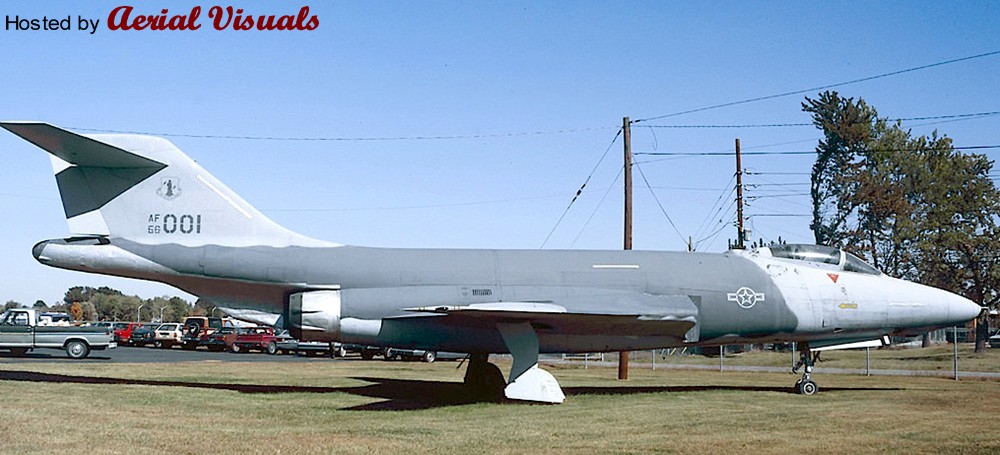
This preserved machine wore a rather unusual (for a Voodoo) ‘Hill’ low-viz scheme with toned-down markings, quite similar to the late USAF F-4 Phantom IIs of the early Eighties. The big aircraft looked quite good in this simple livery, and I kept the idea of a Hill scheme Voodoo in the back of my mind for some years until I recently had the opportunity to buy a cheap Matchbox Voodoo w/o box and decals. With its optional (and unique) RF-101B parts I decided to take the Hill Voodoo idea to the hardware stage and create another submission to the “Reconnaissance and Surveillance” group build at whatifmodellers.com around July 2021: an ANG recce conversion of a former two-seat interceptor, using the RF-101B as benchmark but with a different suite of sensors.
However, the Matchbox Voodoo kit is rather mediocre, and in a rather ambitious mood I decided to “upgrade” the project with a Revell F-101B as the model’s basis. This kit is from 1991 and a MUCH better and finely detailed model than the rather simple Matchbox kit from the early Eighties. In fact, the Revell F-101B is actually a scaled-down version of Monogram’s 1:48 F-101B model kit from 1985, with many delicate details. But while this downscaling practice has produced some very nice 1:72 models like the F-105D or the F-4D, the scaling effect caused IMHO in this case a couple of problems. Revell's assembly instructions for the 1:72 kit are not good, either. While the step-by-step documentation is basically good, some sketches are so cluttered that you cannot tell where parts in the cockpit or on the landing gear are actually intended to be placed and how. This is made worse by the fact that there are no suitable markings on the parts – you are left to guessing.
Worse, there is a massive construction error: the way the wings section is to be assembled and mounted to the hull is impossible! The upper wing halves have locator pins for the fuselage, but they are supposed to be glued to the lower wing half (which also encompasses the aircraft's belly) and the mounted to the hull. The locator pins make this impossible, unless you bend the lower wing section to a point where it might warp or break, or you just cut the pins off - and live with some instability. Technically the upper wing halves have to be mounted to the fuselage before you glue the lower wing section to them, but I am not certain if this would work well because you also have to assemble the air intakes at the same time “from behind”, which is only feasible when the wings have already been completed but still left away from the fuselage. It’s a nonsense construction! I cannot remember when I came across a kit the last time with such an inherent design flaw?
Except for the transplanted RF-101B nose section, which did not fit well because the Matchbox Voodoo apparently has a more slender nose, the Revell kit was built mostly OOB. However, this is already a challenge in itself because of the kit’s inherent flaws (see above), its complex construction and an unorthodox assembly sequence, due to many separate internal modules including the cockpit tub, a separate (fully detailed) front landing gear well, a rotating weapon bay, air intakes with complete ducts, and the wing section. A fiddly affair.
Only a few further changes beyond the characteristic camera fairing under the radome were made. The rotating weapon bay was faired-over with the original weapon pallet, just fixing it into place and using putty to blend it into the belly. The small underwing pylons (an upgrade that actually happened to some late Voodoos) were taken from a vintage Revell F-16. The SLAR antenna fairings along the cockpit flanks were created with 0.5mm styrene sheet and some PSR. They are a little too obvious/protruding, but for a retrofitted solution I find the result acceptable. The drop tanks came from the Revell kit, the underwing ordnance consists of an ALQ-119 ECM pod from a Hasegawa aftermarket set and a SUU-42 dispenser, scratched from a Starfighter ventral drop tank, bomb fins and the back of a Soviet unguided missile launcher.
Painting and markings:
Very simple and basic. While I originally wanted to adopt the simple two-tone ‘Hill’ scheme from the gate guard for my fictional Voodoo, I eventually settled for the very similar but slightly more sophisticated ‘Egypt One’ scheme that was introduced with the first F-16s – it just works better on the F-101’s surfaces. This scheme uses three grey tones: FS 36118 (Gunship Gray, ModelMaster 1723) for the upper wing surfaces, the “saddle” on the fuselage and the canopy area with an anti-glare panel, FS 36270 (Medium Grey, Humbrol 126) on the fin and the fuselage area in front of the wing roots, and FS 36375 (Light Ghost Grey, Humbrol 127) for all lower surfaces, all blended into each other with straight but slightly blurred edges (created with a soft, flat brush). The radome and the conformal antennae on the flanks became Revell 47 for a consistent grey-in-grey look, but with a slightly different shade. The model received an overall black ink washing and some post panel shading, so that the large grey areas would not look too uniform.
As an updated USAF aircraft I changed the color of the landing gear wells’ interior from green zinc chromate primer to more modern, uniform white, even though the red inside of the covers was retained. The interior of the flaps (a nice OOB option of Revell’s kit) and the air brakes became bright red, too.
The cockpit retained its standard medium grey (Humbrol 140, Dark Gull Grey) interior and I used the instrument decals from the kit – even though these did not fit well onto the 3D dashboards and side consoles. WTF? Decal softener came to the rescue. The exhaust area was painted with Revell 91 (Iron) and Humbrol’s Steel Metallizer (27003), later treated with graphite for a dirty, metallic shine.
Markings/decals primarily come from a 1:72 Hi-Decal F-4D sheet that contains (among others) several Texas ANG Phantoms from the mid-Eighties. Some stencils were taken over from the original Voodoo sheet, the yellow formation lights had to be procured from a Hasegawa F-4E/J sheet (the Matchbox sheet was lost and the Revell sheet lacks them completely!). The characteristic deep yellow canopy sealant stripes came from a CF-101 sheet from Winter Valley Decals (today part of Canuck Models as CAD 72008). I was lucky to have them left over from another what-if build MANY moons ago, my fictional CF-151 kitbashing.
Everything went on smoothly, but the walkway markings above the air intakes became a problem. I initially used those from the Revell sheet, which are only the outlines so that the camouflage would still be visible. But the decal film, which is an open square, turned out to be so thin that it wrinkled on the curved surface whatever I tried, and what looked like a crisp black outline on the white decal paper turned out to be a translucent dark blue with blurry edges on the kit. I scrapped them while still wet… Enter plan B: Next came the walkway markings from the aforementioned Winter Valley sheet, which were MUCH better, sharper and opaque, but they included the grey walking areas. While the tone looked O.K. on the sheet it turned out to be much too light for the all-grey Voodoo, standing out and totally ruining the low-viz look. With a bleeding heart I eventually ripped them off of the model with the help of adhesive tape, what left light grey residues. Instead of messing even more with the model I finally decided to embrace this accident and manually added a new black frame to the walkway areas with generic 2mm decal stripe material from TL Modellbau The area now looks rather worn, as if the camouflage had peeled off and light grey primer shows through. An unintentional result, but it looks quite “natural”.
The “Rhino Express” nose art was created with Corel Draw and produced with a simple inkjet printer on clear decal sheet. It was inspired by the “toenail” decoration on the main landing gear covers, a subtle detail I saw IIRC on a late CF-101B and painted onto the model by hand. With its all-grey livery, the rhino theme appeared so appropriate, and the tag on the nose appeared like a natural addition. It’s all not obvious but adds a personal touch to the aircraft.
Finally, after some more exhaust stains had been added to various air outlets around the hull, the model was sealed with matt acrylic varnish, position lights were added with clear paint and the camera windows, which had been created with black decal material, received glossy covers. The IRST sensor was painted with translucent black over a gold base.
Well, while the all-grey USAF livery in itself is quite dull and boring, but I must say that it suits the huge and slender Voodoo well. It emphasizes the aircraft's sleek lines and the Texas ANG fin flash as a colorful counterpoint, as well as the many red interior sections that only show from certain angles, nicely break the adapted low-viz Egypt One livery up. The whole thing looks surprisingly convincing, and the subtle rhino markings add a certain tongue-in-cheek touch.
+++ DISCLAIMER +++
Nothing you see here is real, even though the conversion or the presented background story might be based historical facts. BEWARE!
In July 1967, the first Swedish Air Force student pilots started training on the Saab 105, a Swedish high-wing, twin-engine trainer aircraft developed in the early sixties as a private venture by Saab AB. The Swedish Air Force procured the type for various roles and issued the aircraft with the designation Sk 60.
The Sk 60 entered service in 1967, replacing the aging De Havilland Vampire fleet, and had a long-lasting career. But in the late Eighties, by which point the existing engines of the Swedish Air Force's Sk 60 fleet were considered to be towards the end of their technical and economic lifespan and the airframes started to show their age and wear of constant use, the Swedish Air Force started to think about a successor and/or a modernization program.
Saab suggested to replace the Saab 105’s Turbomeca Aubisque engines with newly-built Williams International FJ44 engines, which were lighter and less costly to operate, but this was only regarded as a stop-gap solution. In parallel, Saab also started work for a dedicated new jet trainer that would prepare pilots for the Saab 39 Gripen – also on the drawing boards at the time – and as a less sophisticated alternative to the promising but stillborn Saab 38.
The Saab 38 (also known as B3LA or A 38/Sk 38) was a single-engine jet trainer and attack aircraft planned by Saab during the 1970s and actually a collaboration between Saab and the Italian aircraft manufacturer Aermacchi (the aircraft resembled the AMX a lot). It was to replace the older Saab 105 jet trainer in the Swedish Air Force, too, but the aircraft never got past the drawing board and was canceled in 1979 in favor of the more advanced Saab JAS 39 Gripen multi-role fighter.
Anyway, this decision left Sweden without a replacement for the Sk 60 as transitional trainer and as a light attack and reconnaissance aircraft.
In 1991, Saab presented its new trainer design, internally called "FSK900", to the Swedish Air Force. The aircraft was a conservative design, with such a configurational resemblance to the Dassault-Dornier Alpha Jet that it is hard to believe Saab engineers didn't see the Alpha Jet as a model for what they wanted to do. However, even if that was the case, the FSK900 was by no means a copy of the Alpha Jet, and the two machines can be told apart at a glance. FSK900 had a muscular, rather massive appearance, while the Alpha Jet was more wasp-like and very sleek. The FSK900 was also bigger in length and span and had an empty weight about 10% greater.
The FSK900 was mostly made of aircraft aluminum alloys, with some control surfaces made of carbon-fiber / epoxy composite, plus very selective use of titanium. It had high-mounted swept wings, with a supercritical airfoil section and a leading-edge dogtooth; a conventional swept tail assembly; tricycle landing gear; twin engines, one mounted in a pod along each side of the fuselage; and a tandem-seat cockpit with dual controls.
The wings had a sweep of 27.5°, an anhedral droop of 7°, and featured ailerons for roll control as well as double slotted flaps. The tailplanes were all-moving, and also featured an anhedral of 7°. An airbrake was mounted on each side of the rear fuselage. Flight controls were hydraulic, and hydraulic systems were dual redundant.
The instructor and cadet sat in tandem, both on zero-zero ejection seats, with the instructor's seat in the rear raised 27 centimeters (10.6 inches) to give a good forward view. The cockpit was pressurized and featured a one-piece canopy, hinged open to the right, that provided excellent visibility.
The landing gear assemblies all featured single wheels, with the nose gear retracting forward and the main gear retracting forward and into the fuselage, featuring an antiskid braking system. The twin engines were two Williams International FJ44-4M turbofans without reheat, each rated at 16.89 kN (3,790 lbst). These were the same engines, that Saab had also proposed for Saab’s Sk 60 modernization program, even though a less powerful variant for the lighter aircraft.
The FSK900 could be fitted with two pylons under each wing and under the fuselage centerline, for a total of five hardpoint. The inner wing pylons were wet and could be used to carry 450 liter (119 US gallon) external tanks, a total external payload of 2,500 kg (5,500 lb) could be carried.
External stores included a centerline target winch for the target tug role, an air-sampling pod for detection of fallout or other atmospheric pollutants, jammer or chaff pods for electronic warfare training, a camera/sensor pod and a baggage pod for use in the liaison role. The aircraft also featured a baggage compartment in the center fuselage, which also offered space for other special equipment or future updates.
Potential armament comprised a conformal underfuselage pod with a single 27 mm Mauser BK-27 revolver cannon with 120 rounds (the same weapon that eventually went into the Saab Gripen).
Other weapons included various iron and cluster bombs of up to 454 kg (1.000 lb) caliber, unguided missiles of various calibers and the Rb.74 (AIM-9L Sidewinder) AAM. A radar was not mounted, but the FSK900’s nose section offered enough space for a radome.
The Swedish Air Force accepted the Saab design, leading to a contract for two nonflying static-test airframes and four flying prototypes. Detail design was complete by the end of 1993 and prototype construction began in the spring of 1994, leading to first flight of the initial prototype on 29 July 1994. The first production "Sk 90 A", how the basic trainer type was officially dubbed, was delivered to the Swedish Air Force in 1996.
In parallel, a contract was signed for the re-engining of 115 Saab Sk 60 aircraft in 1993; the number of aircraft to be upgraded was subsequently reduced as a result of cuts to the defense budget and the advent of the FSK900, of which 60 were ordered initially.
The Sk 90 was regarded as strong, agile, and pleasant to fly, while being cheap to operate. Sk 90 As flying in the training role typically painted in the unique “Fields & Meadows” splinter camouflage, although decorative paint jobs showed up on occasion and many aircraft received additional dayglow markings.
Some of the few aircraft given to operational squadrons, which used them for keeping up flight hours and as hacks, had apparently been painted in all-grey camouflage to match the combat aircraft they shared the flight line with.
With the Sk 90 S a new variant was soon introduced, replacing the Sk 60 C, two-seat ground attack/reconnaissance version for the Swedish Air Force with an extended camera nose. It featured a similar camera arrangement to the Sk 60 C with a panoramic camera, plus an avionics palet in the baggage compartment for a modular DICAST (Digital Camera And Sensor Tray) pod under the fuselage. Unlike the Sk 60 C, which was converted from existing Sk 60 A trainers, the Sk 90 S was an original design. 20 were delivered until 1997, together with the standard trainers, which were kept on the production lines at slow pace until 1999.
A total of 108 production Sk 90s were built, and the Swedish Air Force has no further requirement for new Sk 90s at present. Upgrades are in planning, including fit of at least some Sk 90s with a modern "glass cockpit" to provide advanced training for the Saab Gripen (which had entered service in June 1992), and a full authority digital engine control (FADEC) for the FJ44-4M turbofans. Integration of the Rb.75 (the AGM-65A/B Maverick in Swedish service) together with a pod-mounted FLIR camera system was also suggested, improving the Sk 90’s attack capability dramatically. These updates were started in 2000. The modified aircraft received the designation Sk 90 B and Sk 90 SB, respectively, and until 2006 the whole fleet was updated.
Tests were also made with reinforced underwing pylons that would allow the carriage of the RBS-15 anti-ship missile. Even though the Sk 90 did not carry a radar, the missile-armed trainers were considered as a linked multiplicators for Saab 39s with the appropriate avionics, so that salvoes of multiple missiles could be launched in order to overload ship defences and improve hit probability. While the latter assumption was proved as correct during field trials with two modified Sk 90s, the missiles’ extra drag and the consequent loss in agility, speed and range made the concept unpractical, since the armed Sk 90 could not keep up with the Saab 39, limit reaction time and would offer an easy target.
Another plan was the Sk 90 C, a two-seater with enhanced attack capabilities. Its most distict feature was a simplified PS-05/A pulse-Doppler X band multi-mode radar, developed by Ericsson and GEC-Marconi for the JAS 39 Gripen.
The system was based on the Blue Vixen radar for the Sea Harrier that also served as the basis for the Eurofighter's CAPTOR radar, and it would allow a highly improved air-to-air and air-to-ground capability, also in better concunction with the Saab Gripen as lead aircraft. Two technology demonstrators were converted from Sk 90 A trainers, but the project was shelved - due to budget restrictions and simply through the fact that the JAS 39 Gripen offered anything the Swedish Air Force had called for in just one, single weapon system, so that the Sk 90 remained in its advanced trainer and tactical recce role. The technology package was offered to foreign customers, though.
Despite its qualities and development potential, the Sk 90 did not attain much foreign interest. It suffered from bad timing and from the focus on domestic demands. It came effectively 10 years too late to be serious export success, and the Sk 90 was very similar to the Dassault/Dornier Alpha Jet (even though it was cheaper to operate) - at a time when the German Luftwaffe started to prematurely phaze out its attack variant and flooded the market with cheap second hand aircraft in excellent condition. Besides, the Saab Sk 90 had, with the BAe Hawk, another proven competitor with a long operational track record all over the world.
Modest foreign sales could be secured, though: Austria procured 36 Sk 90 Ö in 2002 (basically comparable with the updated Sk 90 B), replacing its Saab 105 fleet and keeping up its close connection with Saab since the Seventies. Malaysia showed interest, too, as well as Singapore, Myanmar, Finland, Poland and Hungary.
The latest interest came from the Republic of Scotland in late 2017 – after the country’s separation from the United Kingdom and building an independent air force with a supplier from a neutral country.
The Republic of Scotland’s Air Corps (RoScAC) started negotiations with Saab and the Swedish government over either eight newly built or refurbished, older Sk 90 As that were updated to C standard with the PS-05/A radar.
Scotland additionally showed interest in a small fleet of 1st generation Saab 39 interceptors that would replace the RAF fighters based on Scottish ground.
General characteristics:
Crew: two pilots in tandem
Length incl. pitot: 13.0 m (42 ft 8 in) for the A trainer, 13.68 m (44 ft 10 in) for the S variant
Wingspan: 9.94 m (32 ft 7 in)
Height: 4.6 m (15 ft 1 in)
Empty weight: 3,790 kg (8,360 lb)
Max. takeoff weight: 7,500 kg (16,530 lb)
Powerplant:
2× Williams International FJ44-4M turbofans without reheat, rated at 16.89 kN (3,790 lbst) each
Performance:
Maximum speed: 1,038 km/h (645 mph)
Range: 1,670 km (900 nm)
Armament:
No internal gun; five hardpoints for 2,500 kg (5,500 lb) of payload and a variety of ordnance
The kit and its assembly:
A simple kit travesty! This is basically the 1:72 Kawasaki T-4 from Hasegawa, with little modifications.
Originally, I wondered what an overdue Saab 105 replacement could or would look like? The interesting Saab 38 never saw the light, as mentioned above, there was also an A-10-style light attack aircraft (maybe to be built as a kitbashing some day...) and I assume that neutral Sweden would rather develop its own aircraft than procure a foreign product.
Consideration of the BAe Hawk, Alpha Jet and the L-39 Albatros as inspirations for this project, I eventually came across the modern but rather overlooked Japanese Kawasaki T-4 trainer – and found that it had a certain Swedish look about it? Hmm... And coupled with a very characteristic paint scheme, like “Fields & Meadows”, maybe…?
I wanted to keep things simple, though, so the T-4 was mostly built OOB. A pleasant experience. The kit is relatively simple and fit is very good, with only minimal PSR necessary.
The only changes are the underwings hardpoints, which come from a Heller SEPECAT Jaguar, the pair of drop tanks (from an Academy F-5E, IIRC), a scratched recce pod for the ventral hardpoint and a modified bow section. This camera nose is a transplant from a Marivox Saab 105, assuming that the new trainer would be employed in similar roles as the Sk 60. The respective Swedish kit comes with a lot of optional parts, including the extended Sk 60 C’s camera nose - and it fits very well onto the T-4's rounded nose.
Painting and markings:
Well, when building a kit is not a true challenge, maybe the paint job is? The T-4 in a "Fields & Meadows" livery was the initial inspiration for this build, so I tried to stick with the concept as far as possible, even though I'd assume that Swedish aircraft in the kit's time frame would rather be grey with subdued markings. But there's hardly anything as Swedish and spectacular as "Fields & Meadows", and this scheme would also be perfect for the tactical recce role of this build.
The pattern was loosely inspired by the Saab Viggens’ scheme (I found pictures of Sk 60 in Fields & Meadows, but could not puzzle together a complete view) as benchmark.
Painting was done with a fine brush (size 2), free-handedly. Even the waterline was created without masking tape - a clean, bigger brush (size 6) was enough to create the sharp edge. This sounds bizarre and maybe suggest a masochistic touch, but it actually worked better than expected - and I was in the lucky situation that I did not have to slavishly copy and recreate the splinter pattern on a real-world model. ;-)
Finding proper tones for the famous and very characteristic Swedish paint scheme was not easy, though. Pictures of real aircraft vary largely, light conditions and weathering make a proper identification difficult, to say the least. Since I wanted a simple solution (a lot of corrections during the painting process was expected), I settled upon the following enamel tones:
• Modelmaster 2060, RAF Dark Green
• Humbrol 150, Forest Green FS 34127
• Humbrol 72, Khaki Drill, for the earth tone
• A 1:1 mix of Humbrol 33 (Flat Black) + Modelmaster 2094 (RAL 7021) for a very dark grey
• Humbrol 247 (RLM 76) for the undersides
Painting was done from black (starting here because it was the only mixed tone), then the earth tone, light green and finally the dark green - a slow (2 full days) but rather uncomplicated process. But I think that the effort paid out, and helps selling the fictional Sk 90 idea.
The cockpit was painted in neutral grey, while the landing gear and the air intakes became white. A very Swedish touch are the bright green headrests - seen on Saab 37.
The markings were kept simple, puzzled together from various sources. Tactical codes come from a Heller Saab 37 Viggen sheet, while the roundels come from an RBD Models sheet (great stuff!) from Sweden - they actually belong to a Saab 32, but since the roundel sizes are normed the transplant onto the smaller aircraft here was easy and even plausible.
Some stencils were taken from the T-4 OOB sheet or gathered together from the scrap box, e .g. the "FARA" warnings.
The silver trim at the flaps and the fin rudder were made with generic 0.5mm decal stripes in silver. Similar strips in black were used to create the de-icers on the wings' leading edges.
Finally, the kit was sealed with matt acrylic varnish (Italeri).
Not tough to build, but still a challenge to paint. But the result is spectacular, and the T-4 under foreign flag looks disturbingly plausible. How could Sweden hide this aircraft from the public for so long...?
And it's certainly not the last T-4 I will build. A Scottish aircraft, as mentioned in the background, is a hot candidate - but the aircraft has a lot of OOB whiffing potential...
+++ DISCLAIMER +++
Nothing you see here is real, even though the conversion or the presented background story might be based on historical facts. BEWARE!
Some background:
The ZSU-62 (Zenitnaya Samokhodnaya Ustanovka = anti-aircraft self-propelled mount) was a potential successor for the Soviet ZSU-57-2 SPAAG, developed in parallel with the ZSU-23-4. But unlike its brethren, the ZSU-62 was only produced in limited numbers, but it received limited fame during its late operational second-line career when it was successfully deployed to Afghanistan.
The ZSU’62’s roots were laid down just after WWII with the ZSU-57-2. The first prototype (Objekt 500) was completed in the summer of 1950, production began in 1955. The vehicle was built using a modified chassis of the new T-54 tank and was armed with two S-68 57 mm cannons – at the time the most powerful guns mounted in an anti-aircraft system. The modification of the chassis included reducing the road wheels per side to four and using lighter armor. The ZSU-57-2 was powered by a V-54 12-cylinder diesel engine providing 520 hp. Despite the weight of 28 tons, thanks to the strong engine, the maximum speed was 50 km/h. With a fuel load of 850 liters, the operational range was 420 km.
Each cannon had a (theoretical) rate of fire of 240 rounds per minute with a muzzle velocity of 1,000 m/s. Maximum horizontal range was 12 km (with an effective range against ground targets of up to 4 km / 2.5 miles), maximum vertical range was 8.8 km (with a maximum effective vertical range of 4.5 km / 14,750 ft). The effective range, when used against flying targets, was 6 km. Armor-piercing rounds were able to penetrate 110 mm armor at 500 m or 70 mm armor at 2,000 m (at 90° impact angle).
Rate of fire was 120 RPM, but this was only a theoretical number, because each gun was fed with separate four-shot magazines so that only bursts and no continuous fire was possible. Both fragmentation and armor-piercing ammunition were available. The ZSU-57-2’s total ammunition load was 300 rounds, with 176 rounds being stored inside the turret and the remaining in the hull. To efficiently operate the vehicle, six crew members were needed: commander, gunner, loader, driver, and two sight adjusters.
The ZSU-57-2 had serious firepower that could easily destroy any aerial target but had many issues. The greatest weaknesses were the lack of modern range-finding and radar equipment, the impossibility of engaging targets at night or while on the move, the lack of protection for its crew (being open-topped), and low ammunition count. Nevertheless, more than 2.000 ZSU-57-2s were eventually built. While many would be sold to other Warsaw Pact countries, like East Germany, Romania, and Poland, its service within the Soviet Army was limited, because of its many operational deficiencies.
This led in 1957 to a new SPAAG program for the Soviet Army and initiated the development of the ZSU-23-4 "Shilka", the ZSU-37-2 "Yenisei" and a new ZSU-57-2 “Kama” (all baptized after Russian rivers) with the outlook to replace the original ZSU-57-2 by the mid to late Sixties. These vehicles were intended for AA defense of military facilities, troops, and mechanized columns on the march. “Shilka” was intended for close range defense (esp. against low-flying attack helicopters) while the more powerful guns of "Yenisei" and “Kama” were judged to be effective at covering the inner dead-zone of Soviet surface-to-air missile systems between 1.000 and 6.000 m altitude, with a focus on attack aircraft and more heavily armored targets.
All designs were based on existing tracked chassis’ and featured completely enclosed turrets as well as a proven radar system, the RPK-2 "Tobol" radar (NATO designator: "Gun Dish"). The ZSU-37-2 was soon dropped in favor of the higher firepower and range of the 57mm guns, so that both “Shilka” and “Kama” entered the hardware stage at Omsk Works No. 174.
However, “Kama” lagged behind the “Shilka” development because several technical and conceptual problems had to be solved. For instance, even though the armament still consisted of two proven S-68 cannon, the weapons’ mount had to be developed new to fit into the enclosed cast turret. To save space, both weapons were now mounted directly side-by-side. Their feeding system was furthermore changed from magazines to belts, what considerably improved the SPAAG’s firepower and now allowed continuous fire at a higher rate of fire of 150 RPM per gun. For sufficient flexibility, a belt-switching mechanism allowed to choose between two different ammunition supplies: each gun had supplies of 220 and 35 rounds, normally occupied with HE fragmentation and armor-piercing tracer (AP-T) shells, respectively, against aerial and armored ground targets. Changing between the two feeds just took a couple of seconds.
The twin S-68s were recoil-operated and the whole mount (without feeding mechanism) weighed 4,500 kg. The guns had a recoil of between 325 and 370 mm, and each air-cooled gun barrel, fitted with a muzzle brake, was 4365 mm long (76.6 calibers). The weapons could be elevated or depressed between −5° and +80° at a speed of between 0.3° and 32° per second, while the turret could traverse 360° at a speed of between 0.2° and 52° per second. Drive was from a direct current electric motor and universal hydraulic speed gears.
The “Kama” crew numbered four: driver (in the hull), commander, gunner and radar operator (all in the turret). The heavy guns, their ammunition supply and the radar system had to be housed in a turret, together with decent armor, and this resulted in a considerable volume and weight (a single 57 mm projectile alone already weighed 2.8 kg). Several layouts were tested, but weight and volume of the systems made it impossible to mate the “Kama” turret on the T-54/55 chassis, which was available in ample numbers for conversions. The limiting factor was the T-54/55’s relatively small turret bearing diameter.
To solve this problem, the “Kama” designers chose the more modern T-62 as chassis basis. It was outwardly very similar to the former T-54/55, but it featured a 2245 mm turret ring (250 mm more than the T-54/55’s bearing) that was able to take a much bigger/wider/heavier turret than its predecessor. Furthermore, the T-62 represented the Soviet Army’s “state of the art”. The choice of the T-62 ensured many component and maintenance communalities with the operational MBT and it also meant that the “Kama” SPAAG could operate in the same environment and the same pace as the T-62. In order to save costs and development time, the T-62 chassis was taken “as is”, with the same engine and armor level as the MBT. There were only minor changes in the electric components, e. g. a more powerful generator for the radar system.
In this combination, “Kama” eventually entered tests and state acceptance trials as “Object 503”. During these tests, some final changes to layout and equipment were made; for instance, the RPK-2’s dish-shaped radome received a retractable mount that allowed the antenna to be raised higher above the turret in order to avoid clutter and to protect the antenna when the vehicle was on the move.
The tests lasted until 1963 and were successful, so that an initial batch of 100 serial production tanks was ordered the same year. In order to avoid confusion with the old ZSU-57-2 from 1955, the new tank with the same armament was pragmatically designated ZSU-62.
Alas, while production of the “Kama” turrets ran up to be mated with T-62 hulls at the Uralvagonzavod factory in Nizhny Tagil, the ZSU-62’s future had already been sealed by the fast pace of technical developments: in the meantime MANPADS (Man Portable Air Defense System) had taken the medium-range SPAAG’s place and a foot soldier could now fulfill the same mission as an expensive and bulky 40 ton tank, so that the medium range/altitude gap between the ZSU-23-4 (which had already entered service) and heavier surface-to-air missile systems would not be filled with a dedicated vehicle anymore. The ZSU-62 had become superfluous the moment it had reached the first frontline units, and large-scale production was immediately stopped.
However, the initial production run was nevertheless completed until 1967, and the ZSU-62s were primarily sent to training units, where the vehicles were – due to their turrets’ shape – nicknamed “черепаха“ (turtle).
This could have been the ZSU-62’s fate, but the Soviet Union’s intervention in Afghanistan brought it back into frontline service. Since December 1978, the Afghan government called on Soviet forces, which were introduced in the spring and summer of 1979 to provide security and to assist in the fight against the mujaheddin rebels. After the killing of Soviet technicians in Herat by rioting mobs, the Soviet government sold several Mi-24 helicopters to the Afghan military and increased the number of military advisers in the country to 3,000. In April 1979, the Afghan government requested that the USSR send 15 to 20 helicopters with their crews to Afghanistan, and on June 16, the Soviet government responded and sent a detachment of tanks, BMPs, and crews to guard the government in Kabul and to secure the Bagram and Shindand airfields. In response to this request, an airborne battalion arrived at the Bagram Air Base on July 7, and ground forces were deployed from Turkmenistan territory into northern Afghanistan, securing the supply lines.
Experience in the mountainous Afghan landscape soon made the shortcomings of standard MBTs apparent, namely their lack of gun elevation, esp. when attacking hideouts and posts in high locations. While the ZSU-23-4 “Shilka” was readily available and used against such targets, it lacked range and firepower to take out protected posts at distances more than 2.000 m away. This led to the decision to send roundabout 40 ZSU-62s to the Afghan theatre of operations, where they were primarily used against ground targets – both fortifications as well as armored and unarmored vehicles. The weapons’ precision and range proved to be valuable assets, with devastating effect, and the vehicles remained in active service until 1985 when their role was more and more taken over by helicopters and aircraft like the new Su-25. The ZSU-62 were, nevertheless, still employed for aerial airfield defense and as a deterrent against ground attacks.
With the USSR’s withdrawal from Afghanistan in 1988 and 1989, the last operational ZSU-62s were retired. In the training units, the vehicles had already been replaced by ZSU-23-4s by 1984.
Specifications:
Crew: Four (commander, gunner, radar operator, driver)
Weight: 37 t (41 short tons; 36 long tons)
Length: 6.63 m (21 ft 9 in) hull only
9.22 m (30 ft 3½ in) with barrel in forward position
Width: 3.30 m (10 ft 10 in)
Height: 3.88 m (12 ft 9 in) with search radar fully extended,
2.84 m (9 ft 3¾ in) with search radar stowed
Suspension: Torsion bar
Ground clearance: 425 mm (16.7 in)
Fuel capacity: 960 l
Armor:
20 mm (hull bottom) – 102 mm (hull front)
Performance:
Speed: 50 km/h (31 mph) on roads,
40 km/h (25 mph) cross country)
Range: 450 km (280 mi) on road;
650 km (400 mi) with two 200 l (53 US gal; 44 imp gal) extra fuel tanks;
320 km (200 mi) cross-country
450 km (280 mi) with two 200-liter extra fuel tanks
Climbing ability: 0.7 m (2.3')
Maximum climb gradient: 30°
Trench crossing ability: 2.5 m (8.2')
Fording depth: 1.0 m (3.3')
Operational range: 500 km (310 mi)
Power/weight: 14.5 hp/tonne (10.8 kW/tonne)
Engine:
1x V-55 12-cylinder 4-stroke one-chamber 38.88 liter water-cooled diesel engine
with 581 hp (433 kW) at 2,000 rpm
Transmission:
Hydromechanical
Armament:
2× S-68 57mm (1.5 in) cannon with 255 rounds each
The kit and its assembly:
This fictional tank model came to be as a classic what-if, based on the question “what could have been a successor of the Soviet ZSU-57-2 SPAAG?”. Not an existential question that comes to your mind frequently, but it made me wonder – also because the real-world successor, the ZSU-23-4 “Shilka”, lacked the ZSU-57-2’s range and large-caliber firepower.
From this conceptual basis I decided to retain the 57mm twin guns, add an RPK-2 radar and mount these into a fully enclosed turret. The latter became a leftover M48 turret, which was suitably bulky, and the gun mount was taken from a Modelcollect E-75 SPAAG. However, both were heavily modified: the gun mount lost its boxy armor protection, just the brass barrels and the joint at the base were retained, the rest was scratched from styrene bits and wire. To accept the much taller weapon mount, the turret front had to be re-sculpted with putty, resulting in a boxier shape with steeper side walls – but the whole affair looks very organic. A simpler commander cupola was used and the whole radar dish arrangement on the rear roof was scratched, too.
The hull came from a Trumpeter T-62, just for the reasons explained in the background: the T-54/55 had a relatively small turret ring, and this caused severe development problems, because the MBT could not take a bigger turret and with it a more powerful cannon. Since this SPAAG would have been developed a couple of years later than the T-54/55, its successor, the T-62, appeared logical, and the “marriage” with the M48 turret worked like a charm. Even the turret’s adapter had the same diameter as the hull opening, I just had to modify the notches that hold it in place! The hull itself remained unmodified.
Painting and markings:
I wanted to place this SPAAG into the Afghanistan theatre of operations, and this was historically not very easy since I had to bridge some fifteen years of service to make this idea work. However, I found a story for the background, and the model received an appropriate paint scheme, based on real world vehicles around 1980 (actually from a BMP-1 operated in northern Afghanistan).
The camouflage consists of three tones, a pale/greyish sand, an olive drab tone and some contrasts in a dark, dull brown – it reminds of the US Army’s more complex MERDC scheme. The paints became Humbrol 167 (Hemp), Tamiya XF-62 (Olive Drab) and Humbrol 98 (Chocolate), even though the green appears darker than expected due to the high contrast with the sand tone.
The model received an overall washing with dark brown, highly thinned acrylic paint, and some dry-brushing with cream, faded olive drab and light grey. The few markings/decals were taken from the T-62 kit, and everything was sealed with matt acrylic varnish before the lower areas were finally dusted with a greyish-sand brown mix of artist pigments, simulating dust.
A plausible result, even though a cast turret might not appear to be a natural choice for a SPAAG? But the AMX-30 SPAAG from 1969 had a very similar design and there was a German prototype called “MATADOR” (a Gepard forerunner from 1968) that had a turret of similar shape, too. However, the kitbashed/scratched turret looks really good and convincing, and the T-62 hull is a great match for it in shape, size and timeframe. The ZSU-62 turned out way better than hoped for! :D
+++ DISCLAIMER +++
Nothing you see here is real, even though the conversion or the presented background story might be based on historical facts. BEWARE!
Some background:
The Panther tank, officially Panzerkampfwagen V Panther (abbreviated PzKpfw V) with ordnance inventory designation Sd.Kfz. 171, was a German medium tank of World War II. It was used on the Eastern and Western Fronts from mid-1943 to the end of the war. The Panther was intended to counter the Soviet T-34 medium tank and to replace the Panzer III and Panzer IV. Nevertheless, it served alongside the Panzer IV and the heavier Tiger I until the end of the war. It is considered one of the best tanks of World War II for its excellent firepower, protection, and mobility although its reliability in early times were less impressive.
The Panther was a compromise. While having essentially the same Maybach V12 petrol (700 hp) engine as the Tiger I, it had better gun penetration, was lighter and faster, and could traverse rough terrain better than the Tiger I. The trade-off was weaker side armor, which made it vulnerable to flanking fire. The Panther proved to be effective in open country and long-range engagements.
The Panther was far cheaper to produce than the heavy Tiger I. Key elements of the Panther design, such as its armor, transmission, and final drive, were simplifications made to improve production rates and address raw material shortages. Despite this the overall design remain described by some as "overengineered". The Panther was rushed into combat at the Battle of Kursk in the summer of 1943 despite numerous unresolved technical problems, leading to high losses due to mechanical failure. Most design flaws were rectified by late 1943 and early 1944, though the bombing of production plants, increasing shortages of high-quality alloys for critical components, shortage of fuel and training space, and the declining quality of crews all impacted the tank's effectiveness.
Though officially classified as a medium tank, at 44.8 metric tons the Panther was closer to a heavy tank weight and the same category as the American M26 Pershing (41.7 tons), British Churchill (40.7 tons) and the Soviet IS-2 (46 tons) heavy tanks. The Panther's weight caused logistical problems, such as an inability to cross certain bridges, otherwise the tank had a very high power-to-weight ratio which made it highly mobile.
The Panther was only used marginally outside of Germany, mostly captured or recovered vehicles, some even after the war. Japan already received in 1943 a specimen for evaluation. During March–April 1945, Bulgaria received 15 Panthers of various makes (D, A, and G variants) from captured and overhauled Soviet stocks; they only saw limited (training) service use. In May 1946, Romania received 13 Panther tanks from the USSR, too.
After the war, France was able to recover enough operable vehicles and components to equip its army and offer vehicles for sale. The French Army's 503e Régiment de Chars de Combat was equipped with a force of 50 Panthers from 1944 to 1947, in the 501st and 503rd Tank Regiments. These remained in service until they were replaced by French-built ARL 44 heavy tanks.
In 1946, Sweden sent a delegation to France to examine surviving specimens of German military vehicles. During their visit, the delegates found a few surviving Panthers and had one shipped to Sweden for further testing and evaluation, which continued until 1961.
However, this was not the Panther’s end of service. The last appearance by WWII German tanks on the world’s battlefields came in 1967, when Syria’s panzer force faced off against modern Israeli armor. Quite improbably, Syria had assembled a surprisingly wide collection of ex-Wehrmacht vehicles from a half-dozen sources over a decade and a half timeframe. This fleet consisted primarily of late production Panzer V, StuGIII and Jagdpanzer IVs, plus some Hummel SPAAGs and a handful Panthers. The tanks were procured from France, Spain, and Czechoslovakia, partly revamped before delivery.
All of the Panthers Syria came from Czechoslovakia. Immediately after Germany’s collapse in May 1945, the Soviet army established a staging area for surrendered German tanks at a former Wehrmacht barracks at Milovice, about 24 miles north of Prague, Czechoslovakia. By January 1946, a total of roughly 200 operational Panzer IVs and Panthers of varying versions were at this facility. Joining them was a huge cache of spare parts found at a former German tank repair depot in Teplice, along with ammunition collected from all over Czechoslovakia and the southern extremity of the Soviet occupation zone in Germany. Throughout 1946, the Czechoslovak government’s clean-up of WWII battlefields recovered more than one hundred further tank wrecks, of which 80 were pieced back together to operational status and handed over to the Czechoslovakian Army,
In early 1948, the now-nationalized CKD Works began a limited upkeep of the tanks, many of which had not had depot-level overhauls since the war. A few were rebuilt with a Czechoslovak-designed steering system, but this effort was halted due to cost. These tanks remained operational in the Czechoslovak army until the end of 1954, when sufficient T-34s were available to phase them out.
A Syrian military delegation visited Prague from 8 April – 22 April 1955. An agreement was struck for the sale, amongst other items, of 45 Panzer IVs and 15 Panthers. Despite their obsolescence the Czechoslovaks were not about to just give the tanks away and demanded payment in a ‘hard’ western currency, namely British pounds. The cost was £4,500 each (£86,000 or $112,850 in 2016 money), far above what they were probably worth militarily, especially considering the limited amount of foreign currency reserves available to the Damascus government. The deal included refurbishment, a full ammunition loadout for each, and a limited number of spare parts. Nonetheless, the deal was closed, and the tanks’ delivery started in early November 1955.
The Syrians were by that time already having dire problems keeping their French-sourced panzers operational, and in 1958, a second contract was signed with CKD Works for 15 additional Panzer IVs and 10 more Panthers, these being in lesser condition or non-operational, for use as spare parts hulks. An additional 16 refurbished Maybach engines for both types were also included in this contract, as well as more ammunition.
The refurbished Panthers for Syria had their original 7.5 cm KwK 42 L70 replaced with the less powerful Rheinmetall 7.5 cm KwK 40 L48 gun – dictated by the fact that this gun was already installed in almost all other Syrian tanks of German origin and rounds for the KwK 42 L70 were not available anymore. and the Panther’s full ammo load was 87 rounds. The KwK 40 L48 fired a standard APCBC shell at 750 m/s and could penetrate 109 mm (4.3 in) hardened steel at 1.000 m range. This was enough to take out an M4 Sherman at this range from any angle under ideal circumstances. With an APCR shell the gun was even able to penetrate 130 mm (5.1 in) of hardened steel at the same distance.
Outwardly, the gun switch was only recognizable through the shorter barrel with a muzzle brake, the German WWII-era TZF.5f gunsight was retained by the Syrians. Additionally, there were two secondary machine guns, either MG-34s or MG-42s, one coaxial with the main gun and a flexible one in a ball mount in the tank’s front glacis plate.
A few incomplete Panther hulls without turret were also outfitted with surplus Panzer IV turrets that carried the same weapon, but the exact share of them among the Syrian tanks is unknown – most probably less than five, and they were among the batch delivered in the course of the second contract from 1958.
As they had been lumped all together in Czechoslovak army service, the Syrians received a mixed bag of Panzer IV and Panther versions, many of them “half-breeds” or “Frankensteins”. Many had the bow machine gun removed, either already upon delivery or as a later field modification, and in some cases the machine gun in the turret was omitted as well.
An obvious modification of the refurbished Czech export Panthers for Syria was the installation of new, lighter road wheels. These were in fact adapted T-54 wheels from Czechoslovakian license production that had just started in 1957 - instead of revamping the Panthers’ original solid steel wheels, especially their rubberized tread surfaces, it was easier to replace them altogether, what also made spare parts logistics easier. The new wheels had almost the same diameter as the original German road wheels from WWII, and they were simply adapted to the Panther’s attachment points of the torsion bar suspension’s swing arms. Together with the lighter main gun and some other simplifications, the Syrian Panthers’ empty weight was reduced by more than 3 tonnes.
The Czechoslovaks furthermore delivered an adapter kit to mount a Soviet-made AA DShK 12.7mm machine gun to the commander cupola. This AA mount had originally been developed after WWII for the T-34 tank, and these kits were fitted to all initial tanks of the 1955 order. Enough were delivered that some could be installed on a few of the Spanish- / French-sourced tanks, too.
It doesn’t appear that the Czechoslovaks updated the radio fit on any of the ex-German tanks, and it’s unclear if the Syrians installed modern Soviet radios. The WWII German Fu 5 radio required a dedicated operator (who also manned the bow machine gun); if a more modern system was installed not requiring a dedicated operator, this crew position could be eliminated altogether, what favored the deletion of the bow machine gun on many ex-German Syrian tanks. However, due to their more spacious hull and turret, many Panthers were apparently outfitted with a second radio set and used as command tanks – visible through a second whip antenna on the hull.
A frequent domestic Panther upgrade were side skirts to suppress dust clouds while moving and to prevent dust ingestion into the engines and clogged dust filters. There was no standardized solution, though, and solutions ranged from simple makeshift rubber skirts bolted to the tanks’ flanks to wholesale transplants from other vehicles, primarily Soviet tanks. Some Panthers also had external auxiliary fuel tanks added to their rear, in the form of two 200 l barrels on metal racks of Soviet origin. These barrels were not directly connected with the Panther’s fuel system, though, but a pump-and-hose kit was available to re-fuel the internal tanks from this on-board source in the field. When empty or in an emergency - the barrels were placed on top of the engine bay and leaking fuel quite hazardous - the barrels/tanks could be jettisoned by the crew from the inside.
Inclusive of the cannibalization hulks, Syria received a total of roughly 80 former German tanks from Czechoslovakia. However, at no time were all simultaneously operational and by 1960, usually only two or three dozen were combat-ready.
Before the Six Day War, the Syrian army was surprisingly unorganized, considering the amount of money being pumped into it. There was no unit larger than a brigade, and the whole Syrian army had a sort of “hub & spokes” system originating in Damascus, with every individual formation answering directly to the GHQ rather than a chain of command. The Panthers, Panzer IVs and StuG IIIs were in three independent tank battalions, grossly understrength, supporting the normal tank battalions of three infantry brigades (the 8th, 11th, and 19th) in the Golan Heights. The Jagdpanzer IVs were in a separate independent platoon attached to a tank battalion operating T-34s and SU-100s. How the Hummel SPGs were assigned is unknown.
The first active participation of ex-German tanks in Syrian service was the so-called “Water War”. This was not really a war but rather a series of skirmishes between Israel and Syria during the mid-1960s. With increasing frequency starting in 1964, Syria emplaced tanks on the western slope of the Golan Heights, almost directly on the border, to fire down on Israeli irrigation workers and farmers in the Galilee region. Surprisingly (considering the small number available) Syria chose the Panzer IV for this task. It had no feature making it better or worse than any other tank; most likely the Syrians felt they were the most expendable tanks in their inventory as Israeli counterfire was expected. The panzers were in defilade (dug in) and not easy to shoot back at; due to their altitude advantage.
In 1964, Syria announced plans to divert 35% of the Jordan River’s flow away from Israel, to deprive the country of drinking water. The Israelis responded that they would consider this an act of war and, true to their word, engaged the project’s workers with artillery and sniper fire. Things escalated quickly; in 1965, Israeli M4 Shermans on Israeli soil exchanged fire with the Syrian Panzer IVs above inconclusively. A United Nations peacekeeping team ordered both sides to disengage from the border for a set period of time to “cool off”, but the UN “Blue Berets” were detested and considered useless by both the Israelis and Syrians, and both sides used the lull to prepare their next move. When the cooling-off period ended, the Syrians moved Panzer IVs and now some Panthers, too, back into position. However, the IDF had now Centurion tanks waiting for them, with their fire arcs pre-planned out. The Cold War-era Centurion had heavy armor, a high-velocity 105mm gun, and modern British-made optics. It outclassed the WWII panzers in any imaginable way and almost immediately, two Syrian Panzer IVs and a Panther were destroyed. Others were abandoned by their crews and that was the end of the situation.
Syria’s participation in the Six Say War that soon followed in 1967 war was sloppy and ultimately disastrous. Israel initially intended the conflict to be limited to a preemptive strike against Egypt to forestall an imminent attack by that country, with the possibility of having to fight Syria and Jordan defensively if they responded to the operations against Egypt. The war against Egypt started on 5 June 1967. Because of the poor organization of the Syrian army, news passed down from Damascus on the fighting in the Sinai was scarce and usually outdated by the time it reached the brigade level. Many Syrian units (including the GHQ) were using civilian shortwave radios to monitor Radio Cairo which was spouting off outlandish claims of imaginary Egyptian victories, even as Israeli divisions were steamrolling towards the Suez Canal.
Syrian vehicles of German origin during the Six Day War were either painted overall in beige or in a dark olive drab green. Almost all had, instead of tactical number codes, the name of a Syrian soldier killed in a previous war painted on the turret in white. During the Six Day War, no national roundel was typically carried, even though the Syrian flag was sometimes painted to the turret flanks. However just as the conflict was starting, white circles were often painted onto the top sides of tanks as quick ID markings for aircraft, and some tanks had red recognition triangles added to the side areas: Syrian soldiers were notoriously trigger-happy, and the decreased camouflage effect was likely cancelled out by the reduced odds of being blasted by a comrade!
During the evening of 5 June, Syrian generals in Damascus urged the government to take advantage of the situation and mount an immediate invasion of Israel. Planning and preparation were literally limited to a few hours after midnight, and shortly after daybreak on 6 June, Syrian commanders woke up with orders to invade Israel. The three infantry brigades in the Golan, backed up by several independent battalions, were to spearhead the attack as the rest of the Syrian army mobilized.
There was no cohesion at all: Separate battalions began their advance whenever they happened to be ready to go, and brigades went forward, missing subunits that lagged behind. A platoon attempting a southern outflank maneuver tried to ford the Jordan River in the wrong spot and was washed away. According to a KGB report, at least one Syrian unit “exhibited cowardice” and ignored its orders altogether.
On 7 June, 24 hours into their attack, Syrian forces had only advanced 2 miles into Israel. On 8 June, the IDF pushed the Syrians back to the prewar border and that afternoon, Israeli units eliminated the last Egyptian forces in the Sinai and began a fast redeployment of units back into Israel. Now the Syrians were facing serious problems.
On 9 June, Israeli forces crossed into the Golan Heights. They came by the route the Syrians least expected, an arc hugging the Lebanese border. Now for the first time, Syria’s panzers (considered too slow and fragile for the attack) were encountered. The next day, 10 June 1967, was an absolute rout as the Syrians were being attacked from behind by IDF units arcing southwards from the initial advance, plus Israel’s second wave coming from the west. It was later estimated that Syria lost between 20-25% of its total military vehicle inventory in a 15-hour span on 10 June, including eight Panthers. A ceasefire was announced at midnight, ending Syria’s misadventure. Syria permanently lost the Golan Heights to Israel.
By best estimate, Syria had just five Panthers and twenty-five Panzer IVs fully operational on 6 June 1967, with maybe another ten or so tanks partially operational or at least functional enough to take into combat. Most – if not all – of the ex-French tanks were probably already out of service by 1967, conversely the entire ex-Spanish lot was in use, along with some of the ex-Czechoslovak vehicles. The conflict’s last kill was on 10 June 1967 when a Panzer IV was destroyed by an Israeli M50 Super Sherman (an M4 Sherman hull fitted with a new American engine, and a modified turret housing Israeli electronics and a high-velocity French-made 75mm gun firing HEAT rounds). Like the Centurion, the Super Sherman outclassed the Panzer IV, and the Panther only fared marginally better.
Between 1964-1973 the USSR rebuilt the entire Syrian military from the ground up, reorganizing it along Warsaw Pact lines and equipping it with gear strictly of Soviet origin. There was no place for ex-Wehrmacht tanks and in any case, Czechoslovakia had ended spares & ammo support for the Panzer IV and the Panthers, so the types had no future. The surviving tanks were scrapped in Syria, except for a single Panzer IV survivor sold to a collector in Jordan.
Specifications:
Crew: Five (commander, gunner, loader, driver, radio operator)
Weight: 50 tonnes (55.1 long tons; 45.5 short tons)
Length: 6.87 m (22 ft 6 in) hull only
7.52 m (24 ft 7¾ in) overall with gun facing forward
Width: 3.42 m (11 ft 3 in) hull only
3,70 m (12 ft 1¾ in) with retrofitted side skirts
Height: 2.99 m (9 ft 10 in)’
Ground clearance: 56 cm (22 in)
Suspension: Double torsion bar, interleaved road wheels
Fuel capacity: 720 liters (160 imp gal; 190 US gal),
some Syrian Panthers carried two additional external 200 l fuel drums
Armor:
15–80 mm (0.6 – 3.93 in)
Performance:
Maximum road speed: 56 km/h (35 mph)
Operational range: 250 km (160 mi) on roads; 450 km (280 mi)with auxiliary fuel tanks
100 km (62 mi) cross-country
Power/weight: 14 PS (10.1 kW)/tonne (12.7 hp/ton)
Engine & transmission:
Maybach HL230 V-12 gasoline engine with 700 PS (690 hp, 515 kW)
ZF AK 7-200 gearbox with 7 forward 1 reverse gear
Armament:
1× 7,5 cm KwK 40 (L/48) with 87 rounds
2× 7.92 mm MG 34 or 42, or similar machine guns;
one co-axial with the main gun, another in the front glacis plate
with a total of 5.100 rounds (not always mounted)
Provision for a 12.7 mm DShK or Breda anti-aircraft machine gun on the commander cupola
The kit and its assembly:
A rather exotic what-if model, even though it’s almost built OOB. Inspiration came when I stumbled upon the weird Syrian Panzer IVs that were operated against Israel during the Six Day War – vehicles you would not expect there, and after more than 20 years after WWII. But when I did some more research, I was surprised about the numbers and the variety of former German tanks that Syria had gathered from various European countries, and it made me wonder if the Panther could not have been among this shaggy fleet, too?
I had a surplus Dragon Panther Spähpanzer in The Stash™, to be correct a “PzBeobWg V Ausf. G”, an observation and artillery fire guidance conversion that actually existed in small numbers, and I decided to use it as basis for this odd project. The Dragon kit has some peculiarities, though: its hull is made from primed white metal and consists of an upper and lower half that are held together by small screws! An ambiguous design, because the parts do not fit as good as IP parts, so that the model has a slightly die-cast-ish aura. PSR is necessary at the seams, but due to the metal it’s not easy to do. Furthermore, you have to use superglue everywhere, just as on a resin kit. On the other side, surface details are finely molded and crisp, even though many bits have to be added manually. However, the molded metal pins that hold the wheels are very robust and relatively thin – a feature I exploited for a modified running gear (see below).
For the modified Panther in my mind I had to retrograde the turret back to a late standard turret with mantlet parts left over from a Hasegawa kit – they fitted perfectly! The PzBeobWg V only comes with a stubby gun barrel dummy. But I changed the armament, anyway, and implanted an aftermarket white metal and brass KwK 40 L48, the weapon carried by all Syrian Panzer IVs, the Jagdpanzer IVs as well as the StuG IIIs. This standardization would IMHO make sense, even if it meant a performance downgrade from the original, longer KwK 42 L70.
For a Syrian touch, inspired by installations on the Panzer IVs, I added a mount for a heavy DShK machine gun on the commander’s cupola, which is a resin aftermarket kit from Armory Models Group (a kit that consists of no less than five fiddly parts for just a tiny machine gun!).
To change and modernize the Panther’s look further, I gave it side skirts, leftover from a ModelCollect T-72 kit, which had to be modified only slightly to fit onto the molded side skirt consoles on the Panther’s metal hull. A further late addition were the fuel barrels from a Trumpeter T-54 kit that I stumbled upon when I looked for the skirts among my pile of tank donor parts. Even though they look like foreign matter on the Panther’s tail, their high position is plausible and similar to the original arrangement on many Soviet post-WWII tanks. The whip antennae on turret and hull were created with heated black sprue material.
As a modern feature and to change the Panther’s overall look even more, I replaced its original solid “dish” road wheels with T-54/55 “starfish” wheels, which were frequently retrofitted to T-34-85s during the Fifties. These very fine aftermarket resin parts (all real-world openings are actually open, and there’s only little flash!) came from OKB Grigorovich from Bulgaria. The selling point behind this idea is/was that the Panther and T-54/55 wheels have almost the same diameter: in real life it’s 860 vs. 830 mm, so that the difference in 1:72 is negligible. Beneficially, the aftermarket wheels came in two halves, and these were thin enough to replace the Panther’s interleaved wheels without major depth problems.
Adapting the parts to the totally different wheel arrangement was tricky, though, especially due to the Dragon kit’s one-piece white metal chassis that makes any mods difficult. My solution: I retained the inner solid wheels from the Panther (since they are hardly visible in the “3rd row”), plus four pairs of T-54/55 wheels for the outer, more rows of interleaved wheels. The “inner” T-54/55 wheel halves were turned around, received holes to fit onto the metal suspension pins and scratched hub covers. The “outside” halves were taken as is but received 2 mm spacer sleeves on their back sides (styrene tube) for proper depth and simply to improve their hold on the small and rounded metal pin tips. This stunt worked better than expected and looks really good, too!
Painting and markings:
Basically very simple, and I used pictures of real Syrian Panzer IVs as benchmark. I settled for the common green livery variant, and though simple and uniform, I tried to add some “excitement” to it and attempted to make old paint shine through. The hull’s lower surface areas were first primed with RAL 7008 (Khakigrau, a rather brownish tone), then the upper surfaces were sprayed with a lighter sand brown tone, both applied from rattle cans.
On top of that, a streaky mix of Revell 45 and 46 – a guesstimate for the typical Syrian greyish, rather pale olive drab tone - was thinly applied with a soft, flat brush, so that the brownish tones underneath would shine through occasionally. Once dry, the layered/weathered effect was further emphasized through careful vertical wet-sanding and rubbing on all surfaces with a soft cotton cloth.
The rubber side skirts were painted with an anthracite base and the dry-brushed with light grey and beige.
The model then received an overall washing with a highly thinned mix of grey and dark brown acrylic artist paint. The vinyl tracks (as well as the IP spare track links on the hull) were painted, too, with a mix of grey, red brown and iron, all acrylic paints, too, that do not interact chemically with the soft vinyl.
The decals/markings are minimal; the Arabian scribble on the turret (must be a name?), using the picture of a Syrian Panzer IV as benchmark, was painted in white by hand, as well as the white circle on the turret roof. The orange ID triangles are a nice contrast, even though I was not able to come up with real-life visual evidence for them. I just found a color picture of a burned T-34-85 wreck with them, suggesting that the color was a dull orange red and not florescent orange, as claimed in some sources. I also found illustrations of the triangles as part of 1:35 decal sets for contemporary Syrian T-34-85s from FC Model Trend and Star Models, where they appear light red. For the model, they were eventually cut out from decal sheet material (TL-Modellbau, in a shade called “Rotorange”, what appears to be a good compromise).
Dry-brushing with light grey and beige to further emphasize edges and details followed. Finally, the model was sealed with matt acrylic vanish overall, and some additional very light extra dry-brushing with silver was done to simulate flaked paint. Dirt and rust residues were added here and there with watercolors. After final assembly, the lower areas of the model were furthermore powdered with mineral pigments to simulate dust.
The idea of a modernized WWII Panther: a simple idea that turned into a major conversion. With the resin DShK machine gun and T-54/55 wheel set the costs of this project escalated a little, but in hindsight I find that the different look and the mix of vintage German and modern Soviet elements provide this Panther with that odd touch that sets it apart from a simple paint/marking variation? I really like the outcome, and I think that the effort was worthwhile - this fictional Panther shoehorns well into its intended historical framework. :-D
dieses Boot war sehr interessant weil die Figuren beweglich waren und u.a winkten oder den Kopf schüttelten.
+++ DISCLAIMER +++
Nothing you see here is real, even though the conversion or the presented background story might be based historical facts. BEWARE!
Some background:
In October 1951, a heavy tank project was underway to mount an oscillating turret with an automatically loading 120mm Gun on the hull of the 120mm Gun Tank T43. (The T43 would later be serialized as the 120mm Gun Tank M103, America’s last heavy tank.). This was the T57, and the Rheem Manufacturing Company were granted a contract to design and build two pilot turrets and autoloading systems.
During the T57’s development, it became clear that it was feasible to mount a lighter armored version of the T57 turret on the hull of the 90mm Gun Tank T48 (The T48 later became the 90mm Gun Tank M48 Patton). This combination granted the possibility of creating a ‘heavy gun tank’ that was considerably lighter (and therefore more agile and tactically flexible) than any previously designed.
In May 1953, a development project was started to create such a tank. It would be designated the 120mm Gun Tank T77, and another contract was signed with Rheem to create two pilot tanks. The T77 weighed about 50 tons, with armor of the hull being up to 110mm thick. It was originally powered by a 650 hp Continental AVSI-1790-6 V12, air-cooled twin-turbo gasoline engine. This would propel the tank to a speed of 30 mph (48 km/h). The tank was supported on a torsion bar suspension, attached to six road wheels. The drive sprocket was at the rear, while the idler was at the front. The idler wheel was of the compensating type, meaning it was attached to the closest roadwheel by an actuating arm. When the roadwheel reacted to terrain, the idler was pushed out or pulled in, keeping constant track tension. The return of the track was supported by five rollers.
The T77 had a crew of four: The driver’s position was standard for M48 hulls, located centrally in the bow at the front of the hull. Arrangements inside the turret were standard, too: The loader was positioned to the left of the gun, the gunner was on the right with the commander behind him.
The T77’s oscillating turret could be easily mounted to the unmodified 2.1 m (85 inch) turret ring of the M48 hull, and on other tanks, too. It consisted of two actuating parts: a collar that was attached to the turret ring, allowing 360° horizontal traverse, and a pivoting upper part with a long cylindrical ‘nose’ and a low profile flat bustle that held the gun, which could elevate to a maximum of 15 degrees, and depress 8 degrees. It also held the complex loading mechanism and the turret crew.
Both turret halves utilized cast homogeneous steel armor. The sides of the collar were made to be round and bulbous in shape to protect the trunnions that the upper half pivoted on. Armor around the face was 127mm (5 inches) thick, angled at 60 degrees, what meant an effective 10 in (254 mm) equivalent of RHA at the turret front. Maximum armor strength was 137mm (5.3 inches) on the convex sides of the turret, and this dropped to 51 mm (2 inches) on the bustle.
Though it looked like two, there were actually three hatches in the turret’s roof: There was a small hatch on the left for the loader, and the slightly raised cupola for the commander on the right, which featured six periscopes. These two standard hatches were part of a third large, powered hatch, which took up most of the middle of the roof, granting a larger escape route for the crew but also allowed internal turret equipment to be removed easily. It was also a convenient way to replenish the ammunition storage, even though a use under battle conditions was prohibitive. In front of the loader’s hatch was a periscope, housings for a stereoscopic rangefinder were mounted on the sides of the swiveling turret part, and there was another periscope above the gunner’s position, too. Behind the large hatch was the ejection port for spent cartridges, to its right was the armored housing for the ventilator.
The initial Rheem Company turret concept had the gun rigidly mounted to the turret without a recoil system, and the long gun barrel protruded from a narrow nose. The gun featured a quick change barrel but was otherwise basically identical to the 120mm Gun T123E1, the gun being trialed on the T43/M103. However, for the T57/77 turret and the autoloader, it was modified to accept single piece ammunition, unlike the T43/M103, which used separately loading ammo due to the round’s high weight. This new gun was attached to the turret via a conical adapter that surrounded the breech end of the gun. One end screwed directly into the breech, while the front half extended through the ‘nose’ and was secured in place by a large nut. The force created by the firing of the gun and the projectile traveling down the rifled barrel was resisted by rooting the adapter both the breech block and turret ring. As there was no inertia from recoil to automatically open the horizontally sliding breech block, a hydraulic cylinder was introduced. Upon firing the main gun, this hydraulic cylinder was triggered via an electric switch. This new variant of the T123 cannon was designated the 120mm Gun T179. It was fitted with a bore evacuator (fume extractor) and a simple, T-shaped muzzle brake.
A single .30 Caliber (7.62mm) machine gun was mounted coaxially, and another such weapon or a medium 0.5” machine gun could be attached to a mount on the commander’s cupola.
Using standard Armor-Piercing Ballistic Cap Tracer Rounds, the T179 was capable of penetrating 221-millimetre (8.7 in) of 30-degree sloped rolled-homogenous armor at 1,000 yards and 196-millimetre (7.7 in) at 2,000 yards. It could also penetrate 124-millimetre (4.9 in) 60-degree sloped rolled-homogenous armor at 1,000 yards and 114-millimetre (4.5 in) at 2,000 yards.
The T179’s automatic loader was located below the gun and it gave the weapon a projected rate of fire of 30 rounds per minute, even though this was only of theoretical nature because its cylinder magazine only held 8 rounds. After these had been expended, it had to be manually re-loaded by the crew from the inside, and the cannon could not be operated at that time. Ammunition types such as High-Explosive (HE), High-Explosive Anti-Tank (HEAT), Armor Piercing (AP), or Armor-Piercing Ballistic-Capped (APBC) could be fired and be selected from the magazine via a control panel by either the gunner or the tank commander, so that it was possible to quickly adapt to a changing tactical situation – as long as the right rounds had been loaded into the magazine beforehand.
The cannon itself was fed by a ramming arm that actuated between positions relative to the breech and magazine, operating in five major steps:
1) The hydraulically operated ramming arm withdrew a round and aligned it with the breach.
2) The rammer then pushed the round into the breach, triggering it to close.
3) Gun was fired.
4) Effect of gun firing trips the electric switch that opens the breech.
5) Rammer picks up a fresh round, at the same time ejecting the spent cartridge through a trap door in the roof of the turret bustle.
Beyond the 8 rounds ready-for fire in the magazine, the main gun had only a very limited ammunition supply due to the large size of the 1-piece rounds: only 21 more 120 mm rounds could be stored in the hull and at the base of the turret.
After thorough trials, the T77 was, powered by a more fuel-efficient Continental AVDS-1790-2 V12, air-cooled twin-turbo diesel engine with 750 bhp (560 kW), accepted as a replacement for the U.S. Army‘s unloved heavy M103 and introduced as the M77. The first M77s were assembled at the Detroit Arsenal Tank Plant in March 1964. However, the M77 was primarily a support vehicle for standard tank units and reserved for special operations. Therefore, the type’s production numbers remained low: only 173 tanks were eventually built until 1968 and exclusively allocated to U.S. Army units in Western Germany, with a focus on West Berlin and Southern Germany (e.g. in the Fulda Gap), where they were to repel assaults from Eastern Germany and defend vital installations or critical bottlenecks.
Due to its high rate of fire and long range, the M77 was ideally suited for defensive tasks and hit-and-run tactics. But this was, unfortunately, the type’s only selling point: The oscillating turret turned out to be complex, concerning both handling as well as maintenance, and in practice it did not offer the same weapon stability as the M48’s or the later M60’s conventional design, especially when firing during movement. The cramped interior and the many mechanical parts of the bulky autoloader inside of the turret did not make the tank popular among its crews, either. Several accidents occurred during manoeuvers while the loader tried to refill the magazine under combat pressure. A further weakness was the type’s low ammunition stock and the fact that, despite the autoloader, there was still a loader necessary to feed the magazine. The low ammunition stock also heavily limited the tactical value of the tank: typically, the M77 had to leave its position after expending all of its ammunition and move to a second line position, where the huge one-piece rounds could be replenished under safer conditions. But this bound other resources, e. g. support vehicles, and typically the former position had to be given up or supplanted by another vehicle. Operating the M77 effectively turned out to be a logistic nightmare.
During its career, the M77 saw only one major upgrade in the mid-Seventies: The M77A1 was outfitted with a new multi-chamber muzzle brake, muzzle reference and crosswind sensors (the latter was mounted in a small mast on the rear of the turret) and an improved turret stabilization system along with an upgraded turret electrical system. All of these measures were intended to improve the tank’s 1st shot kill probability, esp. at long range. A large AN/VSS-1(V)1 white/IR searchlight was added above the gun barrel, too. All tanks in service were upgraded in this fashion, no new tanks were built. Unlike the M48, neither the M77 nor the Rheem turret or its autoloader system were cleared for export, even though Israel showed interest.
In the early Eighties, there were further plans for another upgrade of the M77 fleet to a potential A2 status. This would have introduced a laser rangefinder (instead of the purely optical device) and a solid state M21 ballistic computer with a digital databus. The M21 would have allowed a pre-programmed selection and fire sequence of different ammunition types from the magazine’s chambers, plus better range and super-elevation correction. However, this did not happen because the M77 had become obsolete through the simple depletion of its exotic 120 mm ammunition from the army’s stocks. Therefore, another plan examined the possibilities of replacing the T179 gun with the 105 mm M68 rifled anti-tank gun, a license-built version of the British L7 gun, which had, despite the smaller caliber, a performance comparable to the bigger 120 mm T179. But since the M48 chassis and its armor concept had become outdated by the time, too, the M77A1 fleet was by 1986 fully replaced by the M60A3, the US Army’s new standard MBT.
Specifications:
Crew: 4 (commander, driver, loader, gunner)
Weight: 51 tons
Length: 6.946 m (22 ft 9.5 in) hull only, 10,66 m (34 ft 11 in) overall w. gun forward
Width: 3.63 m (11 ft 11 in)
Height: 3.08 m (10 ft 1 in)
Suspension: Torsion-bar
Ground clearance: 1 ft 6.2 in (0.46 m)
Fuel capacity: 385 US gal (1,457 l)
Armor:
0.5 – 5.3 in (13 – 137 mm)
Performance:
Speed:
- Maximum, road: 30 mph (48 km/h)
- Sustained, road: 25 mph (40 km/h)
- Cross country: 9.3 to 15.5 mph (15 to 25 km/h)
Climbing capability:
- 40% side slope and 60% max grade
- Vertical obstacle of 36 inches (91 cm)
- 102 inches (2.59 m) trench crossing
Fording depth: Unprepared: 4 ft (1.219 m), prepared: 8 ft (2.438 m)
Operational range: 287 ml (463 km) on road
Power/weight: 16.6 hp (12.4 kW)/tonne
Engine:
1× Continental AVDS-1790-2 V12, air-cooled twin-turbo diesel engine, 750 bhp (560 kW)
Transmission:
General Motors CD-850-3, 2-Fw/1-Rv speed GB
Armament:
1× 120 mm T179 L/60 rifled anti-tank gun with an autoloader and a total of 29 rounds
1× co-axial 7.62 mm M240C machine gun with 3.000 rounds
1× .50 cal (12.7 mm) M2 Browning (600 rounds) or .30 cal (7.62 mm) M73 machine
anti-aircraft machine gun (1.000 rounds) on the commander’s cupola with 600 rounds
The kit and its assembly:
This is another fictional creation, but, like many of my whif builds, it is rooted in reality and an extrapolation of what could have been. The oscillating tower with the M103’s 120 mm cannon and an autoloader was actually developed, and there were several tank projects that made use of it. The T77 was the final proposal, but, like the T57 on the M103 basis and other designs from the Rheem Company, the T77’s development was arduously slow, so that the project was finally canceled in 1957 by the US Ordnance Department. Two turrets were actually built, though, but they were scrapped in February 1958, and the T77 only existed on paper or in model form.
The impulse for this build actually came from a 1:72 resin turret for the T57 project from ModelTrans/Silesian Models. I found the concept cool and the turret had a very futuristic look, so that I bought a set with the vague intention to use it for a mecha conversion someday. Then it gathered dust in the stash, until I recently stumbled upon the 1:72 M103 kit from Dragon and considered a T57 build. But this kit is very rare and expensive, at least here in Germany, so I shelved this plan again. However, I started to play with the idea of a U.S. Army vehicle with a Rheem Company turret. Then I found a Revell M60 kit in the stash and considered it for a whiffy build, but eventually rejected the idea because a turret concept from the late Fifties would hardly make its way onto a tank from the late Seventies or later. When I did further research concerning the Rheem turret, I came across the real T77 project on the basis of the M48, and dug out an ESCI M48A5 from the pile (realizing that I had already hoarded three of them…!), so the M77 project was finally born.
Otherwise, the build was a straightforward affair. The T57 turret is a massive resin piece with a separate barrel and very fine surface details. Some of them, delicate lugs, were unfortunately broken off, already OOB but also by me while handling the pieces. They could be easily replaced with brass wire, though, which was also used to add small rails to the collar. The very long and thin barrel was replaced with a white metal aftermarket piece. It’s actually a barrel for a Soviet T-10 with a complex muzzle brake (made from brass), but the size was just fine and looks very good on this fictional tank.
Some details were added to the turret or transplanted from the M48 kit, e. g. the prominent IR searchlight or the machine gun on the commander cupola. Furthermore, I added a textile seal to the gap between the turret sections and to the barrel’s root, made from paper tissue drenched in thinned white glue. The same method was used to create the searchlight cover, too.
Since the turret base had a smaller diameter than the M48’s attachment opening, I had to improvise a suitable adapter with styrene strips. The M48A5 hull itself was taken OOB.
Painting and markings:
I was happy that I could place this model into a later time frame, so that the U.S. Army’s uniform Olive Drab times were already over. In the 1970s, the US Mobility Equipment Research & Design Command (MERDC) developed a system of camouflage patterns for US Army vehicles. These consisted of a set of standardized patterns for each vehicle, to be used with a set of twelve colours. The local terrain conditions and colours decided which of the paints were to be used, and on which parts of a vehicle. Then, if conditions altered, for example by a change in the weather, or by the unit moving into a new area of operations, the scheme could be quickly adjusted to suit them by replacing only one or two colours by different ones.
For example, if a vehicle was painted in the US & European winter scheme, which had a dark green and a medium brown as its predominant colours, and it started to snow, by overpainting either the green or the brown with white, one of the two snow schemes could be created. This gave a high degree of flexibility, though in practice it was hardly ever actually made use of—most vehicles were painted in one scheme and kept that.
I gave the M77 the “Winter Verdant” MERDC scheme, which was frequently used in Germany. It consists of Forest Green (FS 34079), Earth Red (FS 30117), Sand (FS 30277) and Black (FS 37038). The pattern itself was adapted from the standardized M60 MERDC scheme. Colors used were ModelMaster 1701 and 1710, plus Humbrol 238 and Revell 06. The seals on the turret and the searchlight cover were painted in a faded olive drab, the track segments with a mix of iron, dark grey and red brown.
After basic painting with brushes, the kit received a washing with thinned black and red brown acrylic paint. Decals (taken from the ESCI kit) came next, then the model received an overall dry brushing treatment with Humbrol 72 (Khaki Drill) and 168 (Hemp). Finally, everything was sealed with matt acrylic varnish from the rattle can and the lower hull areas were dusted with mineral pigments, simulating dust and mud.
Another relatively simple conversion, since only the (oscillating) turret was swapped. However, I was skeptical at first because the turret was originally intended for an M103 hull - but mounting it on a smaller M48 chassis worked well, just like in real life!
+++ DISCLAIMER +++
Nothing you see here is real, even though the conversion or the presented background story might be based historical facts. BEWARE!
Some background:
In the late 1970s the Mikoyan OKB began development of a hypersonic high-altitude reconnaissance aircraft. Designated "Izdeliye 301" (also known as 3.01), the machine had an unusual design, combining a tailless layout with variable geometry wings. The two engines fueled by kerosene were located side by side above the rear fuselage, with the single vertical fin raising above them, not unlike the Tu-22 “Blinder” bomber of that time, but also reminiscent of the US-American SR-71 Mach 3 reconnaissance aircraft.
Only few and rather corny information leaked into the West, and the 301 was believed not only to act as a reconnaissance plane , it was also believed to have (nuclear) bombing capabilities. Despite wind tunnel testing with models, no hardware of the 301 was ever produced - aven though the aircraft could have become a basis for a long-range interceptor that would replace by time the PVO's Tupolew Tu-28P (ASCC code "Fiddler"), a large aircraft armed solely with missiles.
Despite limitations, the Tu-28P served well in its role, but the concept of a very fast interceptor aircraft, lingered on, since the Soviet Union had large areas to defend against aerial intruders, esp. from the North and the East. High speed, coupled with long range and the ability to intercept an incoming target at long distances independently from ground guidance had high priority for the Soviet Air Defence Forces. Even though no official requirement was issued, the concept of Izdeliye 301 from the Seventies was eventually developed further into the fixed-wing "Izdeliye 701" ultra-long-range high-altitude interceptor in the 1980ies.
The impulse for this new approach came when Oleg S. Samoylovich joined the Mikoyan OKB after having worked at Suchoi OKB on the T-60S missile carrier project. Similar in overall design to the former 301, the 701 was primarily intended as a kind of successor for the MiG-31 Foxhound for the 21st century, which just had completed flight tests and was about to enter PVO's front line units.
Being based on a long range cruise missile carrier, the 701 would have been a huge plane, featuring a length of 30-31m, a wing span of 19m (featuring a highly swept double delta wing) and having a maximum TOW of 70 tons! Target performance figures included a top speed of 2.500km/h, a cruising speed of 2.100km/h at 17.000m and an effective range of 7.000km in supersonic or 11.000km in subsonic mode. Eventually, the 701 program was mothballed, too, being too ambitious and expensive for a specialized development that could also have been a fighter version of the Tu-22 bomber!
Anyway, while the MiG-31 was successfully introduced in 1979 and had evolved in into a capable long-range interceptor with a top speed of more than Mach 3 (limited to Mach 2.8 in order to protect the aircraft's structural integrity), MiG OKB decided in 1984 to take further action and to develop a next-generation technology demonstrator, knowing that even the formidable "Foxhound" was only an interim solution on the way to a true "Four plus" of even a 6th generation fighter. Other new threats like low-flying cruise missiles, the USAF's "Project Pluto" or the assumed SR-71 Mach 5 successor “Aurora” kept Soviet military officials on the edge of their seats, too.
Main objective was to expand the Foxhound's state-of the-art performance, and coiple it with modern features like aerodynamic instability, supercruise, stealth features and further development potential.
The aircraft's core mission objectives comprised:
- Provide strategic air defense and surveillance in areas not covered by ground-based air defense systems (incl. guidance of other aircraft with less sophisticated avionics)
- Top speed of Mach 3.2 or more in a dash and cruise at Mach 3.0 for prolonged periods
- Long range/high speed interception of airspace intruders of any kind, including low flying cruise missiles, UAVs and helicopters
- Intercept cruise missiles and their launch aircraft from sea level up to 30.000m altitude by reaching missile launch range in the lowest possible time after departing the loiter area
Because funding was scarce and no official GOR had been issued, the project was taken on as a private venture. The new project was internally known as "Izdeliye 710" or "71.0". It was based on both 301 and 701 layout ideas and the wind tunnel experiences with their unusual layouts, as well as Oleg Samoylovich's experience with the Suchoi T-4 Mach 3 bomber project and the T-60S.
"Izdeliye 710" was from the start intended only as a proof-of-concept prototype, yet fully functional. It would also incorporate new technologies like heat-resistant ceramics against kinetic heating at prolonged high speeds (the airframe had to resist temperatures of 300°C/570°F and more for considerable periods), but with potential for future development into a full-fledged interceptor, penetrator and reconnaissance aircraft.
Overall, “Izdeliye 710" looked like a shrinked version of a mix of both former MiG OKB 301 and 701 designs, limited to the MiG-31's weight class of about 40 tons TOW. Compared with the former designs, the airframe received an aerodynamically more refined, partly blended, slender fuselage that also incorporated mild stealth features like a “clean” underside, softened contours and partly shielded air intakes. Structurally, the airframe's speed limit was set at Mach 3.8.
From the earlier 301 design,the plane retained the variable geometry wing. Despite the system's complexity and weight, this solution was deemed to be the best approach for a combination of a high continuous top speed, extended loiter time in the mission’s patrol areas and good performance on improvised airfields. Minimum sweep was a mere 10°, while, fully swept at 68°, the wings blended into the LERXes. Additional lift was created through the fuselage shape itself, so that aerodynamic surfaces and therefore drag could be reduced.
Pilot and radar operator sat in tandem under a common canopy with rather limited sight. The cockpit was equipped with a modern glass cockpit with LCD screens. The aircraft’s two engines were, again, placed in a large, mutual nacelle on the upper rear fuselage, fed by large air intakes with two-dimensional vertical ramps and a carefully modulated airflow over the aircraft’s dorsal area.
Initially, the 71.0 was to be powered by a pair of Soloviev D-30F6 afterburning turbofans with a dry thrust of 93 kN (20,900 lbf) each, and with 152 kN (34,172 lbf) with full afterburner. These were the same engines that powered the MiG-31, but there were high hopes for the Kolesov NK-101 engine: a variable bypass engine with a maximum thrust in the 200kN range, at the time of the 71.0's design undergoing bench tests and originally developed for the advanced Suchoj T-4MS strike aircraft.
With the D-30F6, the 71.0 was expected to reach Mach 3.2 (making the aircraft capable of effectively intercepting the SR-71), but the NK-101 would offer in pure jet mode a top speed in excess of Mach 3.5 and also improve range and especially loiter time when running as a subsonic turbofan engine.
A single fin with an all-moving top and an additional deep rudder at its base was placed on top of the engine nacelle. Additional maneuverability at lower speed was achieved by retractable, all-moving foreplanes, stowed in narrow slits under the cockpit. Longitudinal stability at high speed was improved through deflectable stabilizers: these were kept horizontal for take-off and added to the overall lift, but they could be folded down by up to 60° in flight, acting additionally as stabilizer strakes.
Due to the aircraft’s slender shape and unique proportions, the 71.0 quickly received the unofficial nickname "жура́вль" (‘Zhurávl' = Crane). The aircaft’s stalky impression was emphasized even more through its unusual landing gear arrangement: Due to the limited internal space for the main landing gear wells between the weapons bay, the wing folding mechanisms and the engine nacelle, MiG OKB decided to incorporate a bicycle landing gear, normally a trademark of Yakovlew OKB designs, but a conventional landing gear could simply not be mounted, or its construction would have become much too heavy and complex.
In order to facilitate operations from improvised airfields and on snow the landing gear featured twin front wheels on a conventional strut and a single four wheel bogie as main wheels. Smaller, single stabilizer wheels were mounted on outriggers that retracted into slender fairings at the wings’ fixed section trailing edge, reminiscent of early Tupolev designs.
All standard air-to-air weaponry, as well as fuel, was to be carried internally. Main armament would be the K-100 missile (in service eventually designated R-100), stored in a large weapons bay behind the cockpit on a rotary mount. The K-100 had been under development at that time at NPO Novator, internally coded ‘Izdeliye 172’. The K-100 missile was an impressive weapon, and specifically designed to attack vital and heavily defended aerial targets like NATO’s AWACS aircraft at BVR distance.
Being 15’ (4.57 m) long and weighing 1.370 lb (620 kg), this huge ultra-long-range weapon had a maximum range of 250 mi (400 km) in a cruise/glide profile and attained a speed of Mach 6 with its solid rocket engine. This range could be boosted even further with a pair of jettisonable ramjets in tubular pods on the missile’s flanks for another 60 mi (100 km). The missile could attack targets ranging in altitude between 15 – 25,000 meters.
The weapon would initially be allocated to a specified target through the launch aircraft’s on-board radar and sent via inertial guidance into the target’s direction. Closing in, the K-100’s Agat 9B-1388 active seeker would identify the target, lock on, and independently attack it, also in coordination with other K-100’s shot at the same target, so that the attack would be coordinated in time and approach directions in order to overload defense and ensure a hit.
The 71.0’s internal mount could hold four of these large missiles, or, alternatively, the same number of the MiG-31’s R-33 AAMs. The mount also had a slot for the storage of additional mid- and short-range missiles for self-defense, e .g. three R-60 or two R-73 AAMs. An internal gun was not considered to be necessary, since the 71.0 or potential derivatives would fight their targets at very long distances and rather rely on a "hit-and-run" tactic, sacrificing dogfight capabilities for long loitering time in stand-by mode, high approach speed and outstanding acceleration and altitude performance.
Anyway, provisions were made to carry a Gsh-301-250 gun pod on a retractable hardpoint in the weapons bay instead of a K-100. Alternatively, such pods could be carried externally on four optional wing root pylons, which were primarily intended for PTB-1500 or PTB-3000 drop tanks, or further missiles - theoretically, a maximum of ten K-100 missiles could be carried, plus a pair of short-range AAMs.
Additionally, a "buddy-to-buffy" IFR set with a retractable drogue (probably the same system as used on the Su-24) was tested (71.2 was outfitted with a retractable refuelling probe in front of the cockpit), as well as the carriage of simple iron bombs or nuclear stores, to be delivered from very high altitudes. Several pallets with cameras and sensors (e .g. a high resolution SLAR) were also envisioned, which could easily replace the missile mounts and the folding weapon bay covers for recce missions.
Since there had been little official support for the project, work on the 710 up to the hardware stage made only little progress, since the MiG-31 already filled the long-range interceptor role in a sufficient fashion and offered further development potential.
A wooden mockup of the cockpit section was presented to PVO and VVS officials in 1989, and airframe work (including tests with composite materials on structural parts, including ceramic tiles for leading edges) were undertaken throughout 1990 and 1991, including test rigs for the engine nacelle and the swing wing mechanism.
Eventually, the collapse of the Soviet Union in 1991 suddenly stopped most of the project work, after two prototype airframes had been completed. Their internal designations were Izdeliye 71.1 and 71.2, respectively. It took a while until the political situation as well as the ex-Soviet Air Force’s status were settled, and work on Izdeliye 710 resumed at a slow pace.
After taking two years to be completed, 71.1 eventually made its roll-out and maiden flight in summer 1994, just when MiG-31 production had ended. MiG OKB still had high hopes in this aircraft, since the MiG-31 would have to be replaced in the next couple of years and "Izdeliye 710" was just in time for the potential procurement process. The first prototype wore a striking all-white livery, with dark grey ceramic tiles on the wings’ leading edges standing out prominently – in this guise and with its futuristic lines the slender aircraft reminded a lot of the American Space Shuttle.
71.1 was primarily intended for engine and flight tests (esp. for the eagerly awaited NK-101 engines), as well as for the development of the envisioned ramjet propulsion system for full-scale production and further development of Izdeliye 710 into a Mach 3+ interceptor. No mission avionics were initially fitted to this plane, but it carried a comprehensive test equipment suite and ballast.
Its sister ship 71.2 flew for the first time in late 1994, wearing a more unpretentious grey/bare metal livery. This plane was earmarked for avionics development and weapons integration, especially as a test bed for the K-100 missile, which shared Izdeliye 710’s fate of being a leftover Soviet project with an uncertain future and an even more corny funding outlook.
Anyway, aircraft 71.2 was from the start equipped with a complete RP-31 ('Zaslon-M') weapon control system, which had been under development at that time as an upgrade for the Russian MiG-31 fleet being part of the radar’s development program secured financial support from the government and allowed the flight tests to continue. The RP-31 possessed a maximum detection range of 400 km (250 mi) against airliner-sized targets at high altitude or 200 km against fighter-sized targets; the typical width of detection along the front was given as 225 km. The system could track 24 airborne targets at one time at a range of 120 km, 6 of which could be simultaneously attacked with missiles.
With these capabilities the RP-31 suite could, coupled with an appropriate carrier airframe, fulfil the originally intended airspace control function and would render a dedicated and highly vulnerable airspace control aircraft (like the Beriev A-50 derivative of the Il-76 transport) more or less obsolete. A group of four aircraft equipped with the 'Zaslon-M' suite would be able to permanently control an area of airspace across a total length of 800–900 km, while having ultra-long range weapons at hand to counter any intrusion into airspace with a quicker reaction time than any ground-based fighter on QRA duty. The 71.0, outfitted with the RP-31/K-100 system, would have posed a serious threat to any aggressor.
In March 1995 both prototypes were eventually transferred to the Kerchenskaya Guards Air Base at Savasleyka in the Oblast Vladimir, 300 km east of Mocsow, where they received tactical codes of '11 Blue' and '12 Blue'. Besides the basic test program and the RP-31/K-100 system tests, both machines were directly evaluated against the MiG-31 and Su-27 fighters by the Air Force's 4th TsBPi PLS, based at the same site.
Both aircraft exceeded expectations, but also fell short in certain aspects. The 71.0’s calculated top speed of Mach 3.2 was achieved during the tests with a top speed of 3,394 km/h (2.108 mph) at 21,000 m (69.000 ft). Top speed at sea level was confirmed at 1.200 km/h (745 mph) indicated airspeed.
Combat radius with full weapon load and internal fuel only was limited to 1,450 km (900 mi) at Mach 0.8 and at an altitude of 10,000 m (33,000 ft), though, and it sank to a mere 720 km (450 mi) at Mach 2.35 and at an altitude of 18,000 m (59,000 ft). Combat range with 4x K-100 internally and 2 drop tanks was settled at 3,000 km (1,860 mi), rising to 5,400 km (3,360 mi) with one in-flight refueling, tested with the 71.2. Endurance at altitude was only slightly above 3 hours, though. Service ceiling was 22,800 m (74,680 ft), 2.000 m higher than the MiG-31.
While these figures were impressive, Soviet officials were not truly convinced: they did not show a significant improvement over the simpler MiG-31. MiG OKB tried to persuade the government into more flight tests and begged for access to the NK-101, but the Soviet Union's collapse halted this project, too, so that both Izdeliye 710 had to keep the Soloviev D-30F6.
Little is known about the Izdeliye 710 project’s progress or further developments. The initial tests lasted until at least 1997, and obviously the updated MiG-31M received official favor instead of a completely new aircraft. The K-100 was also dropped, since the R-33 missile and later its R-37 derivative sufficiently performed in the long-range aerial strike role.
Development on the aircraft as such seemed to have stopped with the advent of modernized Su-27 derivatives and the PAK FA project, resulting in the Suchoi T-50 prototype. Unconfirmed reports suggest that one of the prototypes (probably 71.1) was used in the development of the N014 Pulse-Doppler radar with a passive electronically scanned array antenna in the wake of the MFI program. The N014 was designed with a range of 420 km, detection target of 250km to 1m and able to track 40 targets while able to shoot against 20.
Most interestingly, Izdeliye 710 was never officially presented to the public, but NATO became aware of its development through satellite pictures in the early Nineties and the aircraft consequently received the ASCC reporting codename "Fastback".
Until today, only the two prototypes have been known to exist, and it is assumed – had the type entered service – that the long-range fighter had received the official designation "MiG-41".
General characteristics:
Crew: 2 (Pilot, weapon system officer)
Length (incl. pitot): 93 ft 10 in (28.66 m)
Wingspan:
- minimum 10° sweep: 69 ft 4 in (21.16 m)
- maximum 68° sweep: 48 ft 9 in (14,88 m)
Height: 23 ft 1 1/2 in (7,06 m )
Wing area: 1008.9 ft² (90.8 m²)
Weight: 88.151 lbs (39.986 kg)
Performance:
Maximum speed:
- Mach 3.2 (2.050 mph (3.300 km/h) at height
- 995 mph (1.600 km/h) supercruise speed at 36,000 ft (11,000 m)
- 915 mph (1.470 km/h) at sea level
Range: 3.705 miles (5.955 km) with internal fuel
Service ceiling: 75.000 ft (22.500 m)
Rate of climb: 31.000 ft/min (155 m/s)
Engine:
2x Soloviev D-30F6 afterburning turbofans with a dry thrust of 93 kN (20,900 lbf) each
and with 152 kN (34,172 lbf) with full afterburner.
Armament:
Internal weapons bay, main armament comprises a flexible missile load; basic ordnance of 4x K-100 ultra long range AAMs plus 2x R-73 short-range AAMs: other types like the R-27, R-33, R-60 and R-77 have been carried and tested, too, as well as podded guns on internal and external mounts. Alternatively, the weapon bay can hold various sensor pallets.
Four hardpoints under the wing roots, the outer pair “wet” for drop tanks of up to 3.000 l capacity, ECM pods or a buddy-buddy refueling drogue system. Maximum payload mass is 9000 kg.
The kit and its assembly
The second entry for the 2017 “Soviet” Group Build at whatifmodelers.com – a true Frankenstein creation, based on the scarce information about the real (but never realized) MiG 301 and 701 projects, the Suchoj T-60S, as well as some vague design sketches you can find online and in literature.
This one had been on my project list for years and I already had donor kits stashed away – but the sheer size (where will I leave it once done…?) and potential complexity kept me from tackling it.
The whole thing was an ambitious project and just the unique layout with a massive engine nacelle on top of the slender fuselage instead of an all-in-one design makes these aircraft an interesting topic to build. The GB was a good motivator.
“My” fictional interpretation of the MiG concepts is mainly based on a Dragon B-1B in 1:144 scale (fuselage, wings), a PM Model Su-15 two seater (donating the nose section and the cockpit, as well as wing parts for the fin) and a Kangnam MiG-31 (for the engine pod and some small parts). Another major ingredient is a pair of horizontal stabilizers from a 1:72 Hasegawa A-5 Vigilante.
Fitting the cockpit section took some major surgery and even more putty to blend the parts smoothly together. Another major surgical area was the tail; the "engine box" came to be rather straightforward, using the complete rear fuselage section from the MiG-31 and adding the intakes form the same kit, but mounted horizontally with a vertical splitter.
Blending the thing to the cut-away tail section of the B-1 was quite a task, though, since I not only wanted to add the element to the fuselage, but rather make it look a bit 'organic'. More than putty was necessary, I also had to made some cuts and transplantations. And after six PSR rounds I stopped counting…
The landing gear was built from scratch – the front wheel comes mostly from the MiG-31 kit. The central bogie and its massive leg come from a VEB Plasticart 1:100 Tu-20/95 bomber, plus some additional struts. The outriggers are leftover landing gear struts from a Hobby Boss Fw 190, mated with wheels which I believe come from a 1:200 VEB Plasticart kit, an An-24. Not certain, though. The fairings are slender MiG-21 drop tanks blended into the wing training edge. For the whole landing gear, the covers were improvised with styrene sheet, parts from a plastic straw(!) or leftover bits from the B-1B.
The main landing gear well was well as the weapons’ bay themselves were cut into the B-1B underside and an interior scratched from sheet and various leftover materials – I tried to maximize their space while still leaving enough room for the B-1B kit’s internal VG mechanism.
The large missiles (two were visible fitted and the rotary launcher just visibly hinted at) are, in fact, AGM-78 ‘Standard’ ARMs in a fantasy guise. They look pretty Soviet, though, like big brothers of the already not small R-33 missiles from the MiG-31.
While not in the focus of attention, the cockpit interior is completely new, too – OOB, the Su-15 cockpit only has a floor and rather stubby seats, under a massive single piece canopy. On top of the front wheel well (from a Hasegawa F-4) I added a new floor and added side consoles, scratched from styrene sheet. F-4 dashboards improve the decoration, and I added a pair of Soviet election seats from the scrap box – IIRC left over from two KP MiG-19 kits.
The canopy was taken OOB, I just cut it into five parts for open display. The material’s thickness does not look too bad on this aircraft – after all, it would need a rather sturdy construction when flying at Mach 3+ and withstanding the respective pressures and temperatures.
Painting
As a pure whif, I was free to use a weirdo design - but I rejected this idea quickly. I did not want a garish splinter scheme or a bright “Greenbottle Fly” Su-27 finish.
With the strange layout of the aircraft, the prototype idea was soon settled – and Soviet prototypes tend to look very utilitarian and lusterless, might even be left in grey. Consequently, I adapted a kind of bare look for this one, inspired by the rather shaggy Soviet Tu-22 “Blinder” bombers which carried a mix of bare metal and white and grey panels. With additional black leading edges on the aerodynamic surfaces, this would create a special/provisional but still purposeful look.
For the painting, I used a mix of several metallizer tones from ModelMaster and Humbrol (including Steel, Magnesium, Titanium, as well as matt and polished aluminum, and some Gun Metal and Exhaust around the engine nozzles, partly mixed with a bit of blue) and opaque tones (Humbrol 147 and 127). The “scheme” evolved panel-wise and step by step. The black leading edges were an interim addition, coming as things evolved, and they were painted first with black acrylic paint as a rough foundation and later trimmed with generic black decal stripes (from TL Modellbau). A very convenient and clean solution!
The radomes on nose and tail and other di-electric panels became dark grey (Humbrol 125). The cockpit tub was painted with Soviet Cockpit Teal (from ModelMaster), while the cockpit opening and canopy frames were kept in a more modest medium grey (Revell 57). On the outside of the cabin windows, a fat, deep yellow sealant frame (Humbrol 93, actually “Sand”) was added.
The weapon bay was painted in a yellow-ish primer tone (seen on pics of Tu-160 bombers) while the landing gear wells received a mix of gold and sand; the struts were painted in a mixed color, too, made of Humbrol 56 (Aluminum) and 34 (Flat White). The green wheel discs (Humbrol 131), a typical Soviet detail, stand out well from the rather subdued but not boring aircraft, and they make a nice contrast to the red Stars and the blue tactical code – the only major markings, besides a pair of MiG OKB logos under the cockpit.
Decals were puzzled together from various sheets, and I also added a lot of stencils for a more technical look. In order to enhance the prototype look further I added some photo calibration markings on the nose and the tail, made from scratch.
A massive kitbashing project that I had pushed away for years - but I am happy that I finally tackled it, and the result looks spectacular. The "Firefox" similarity was not intended, but this beast really looks like a movie prop - and who knwos if the Firefox was not inspired by the same projects (the MiG 301 and 701) as my kitbash model?
The background info is a bit lengthy, but there's some good background info concerning the aforementioned projects, and this aircraft - as a weapon system - would have played a very special and complex role, so a lot of explanations are worthwhile - also in order to emphasize that I di not simply try to glue some model parts together, but rather try to spin real world ideas further.
Mighty bird!
Bild von meinem Modell des Wiesel 1A0 MK20 Unosom.
Mehr Bilder und der Baubericht auf www.abisz-modellbau.de/modellbau/wiesel-i-von-afv-club/
+++ DISCLAIMER +++
Nothing you see here is real, even though the conversion or the presented background story might be based on historical facts. BEWARE!
Some background:
The ASJA J13 was a Swedish fighter aircraft of the 1930s. It was designed and produced by the AB Svenska Järnvägsverkstädernas Aeroplanavdelning (Swedish Railroad Workshops' Air Plane Department, ASJA) in limited quantities as a transitional aircraft between the last of the biplanes and the first monoplane fighters.
Development under the project designation L13, work on the fighter started in 1930. From the start, the aircraft was to be a monoplane with a parasol layout and a wide, fixed landing gear that could easily be switched between spatted wheels and skis for winter operations. Optimized for the harsh climatic conditions in Northern Europe and with ruggedness and ease of field operations in mind, the L13 was to be powered by a robust Gnome-Rhône 9Krsd radial engine with 500 hp, driving a fixed, wooden two-blade propeller. The airframe was an all-metal construction, covered with fabric except for the front fuselage section (with the engine mount, the main tank and the wings’ main attachment points), which was sheathed with duralumin. The armament consisted of a pair of 8 mm ksp m/22 machine guns (license built .30 AN/M2's) with 500 rounds each, mounted in front of the open cockpit and synchronized to fire through the propeller arc.
The first prototype made its maiden flight in summer 1932, and after successful flight tests, the new fighter was accepted by the Swedish Air Force as J13 and series production started at once, even though at a slow pace because the engines had to be imported and French production was primarily allocated to domestic aircraft production. However, at the same time, the Swedish government was in negotiations with France concerning the procurement of complete aircraft like the Breguet 694 (which later became the S10 reconnaissance aircraft), and in the wake of these discussions, the import of the compact, but also more powerful, Hispano-Suiza 14AB radial engine with ~650 hp for the J13 (and other Swedish types on the drawing board) was considered.
Three initial Hispano-Suiza 14AB engines were delivered in 1933 for tests and development, and the sixth production J13 was modified to carry one of these new engines. Changes primarily consisted of a slightly extended cowling and a new, variable all-metal three-blade propeller, which significantly improved the aircraft’s performance and handling. As another measure to improve the type’s effectiveness, the light 8mm machine guns were replaced by F.N. Mitrailleuse d'Avion Browning 13,2 mm heavy machine guns (later license-built in Sweden as the Akan m/39).
However, during test flights, powerful vibrations were encountered, and the bigger engine as well as the heavier weapons caused stability problems, as the aircraft’s center of gravity had moved forward. However, the new engine raised the aircraft’s top speed by almost 50 km/h (30 mph), bringing the L13 on par with foreign contemporary fighters, so that the project pursued. Both engine problems were eventually cured through a stiffened internal structure around the engine mount and modified wings, which now featured a slight sweep and shifted the center of lift forward. In this form, the aircraft was designated J13B (while the initial version, of which only sixteen aircraft were built, was re-designated J13A) and entered production and service in early 1935. A total of 53 J13Bs were delivered to the Swedish Air Force until November 1936. Argentine and Japanese military representatives tested the rugged aircraft, but placed no orders.
As the J13B entered service, however, it was, despite the improvements, already obsolete. Nevertheless, the J13B received the opportunity to show its qualities: During the Winter War with the Soviet Union. Stalin launched all-out war on Nov. 30, 1939, and the Red Army assaulted the Mannerheim Line, also invading central Finland to sever supply lines from Sweden. The Soviet Navy prowled the coast. Aloft, VVS fighters and bombers struck at ports, cities, and installations. At that time, the Finnish Air Force (FAF) operated 30 Gloster Gladiator fighters, obtained from the UK. Besides the FAF Gladiators, the Swedish Voluntary Air Force came to aide and became responsible for the air defense of northernmost Finland during the conflict. The Swedish Voluntary Air Force’s Flying Regiment F 19 arrived in Finnish Lapland on 10 January 1940 and remained there until the end of hostilities. It fielded twelve Gladiator Mk II fighters (known in Sweden as the J8), six ASJA J13B fighters, five Hawker Hart dive bombers, plus a Raab-Katzenstein RK-26 liaison aircraft and a Junkers F.13 transport aircraft. The aircraft belonged to and were crewed by the Swedish Air Force, but flew with Finnish nationality markings.
While the Finns put up a spirited resistance during the winter of 1939-1940, their troops were ultimately no match for the sheer immensity of the Red Army. In February 1940, following one of the largest artillery bombardments since World War I, the Soviets renewed their onslaught and overran the Finnish defenses on the Karelian Isthmus. With its forces low on ammunition and nearing the brink of exhaustion, Finland agreed to peace terms the following month. Until then, the Swedes of F 19 managed to shoot down at least 10 Soviet planes. The most successful Finnish ace, Oiva Tuominenn, scored 4 victories flying a Swedish J8B (a Gladiator Mk.II).
The J13Bs were less successful, only a single air victory was claimed. This could not be attributed to the J13B’s fighter performance, though, but rather to the fact that the type was primarily used for reconnaissance duties (its parasol design afforded a very good field of view) and ground attacks. The J13B’s heavy machine guns proved to be very effective in the latter role, e.g. strafing troops and vehicles trying to cross Lake Ladoga, Viipuri Bay and other iced-over waterways. Furthermore, the pilots in the outdated Finnish and Swedish aircraft tried in general to avoid aerial combat with Soviet fighters whenever possible, rather attacking bombers. One J13B was lost in aerial combat (shot down by an I-16 monoplane), while another one was destroyed on the ground during an air raid.
In early March 1940, Sweden announced it would not permit any foreign forces to cross its territory to fight in Finland. On March 6, after much debate, a Finnish delegation left for Stockholm, then flew on to Moscow, arriving the next day. There, on March 12, Finnish and Russian conferees signed a treaty of peace. The next day, at 11 a.m. Helsinki time, an uneasy peace returned. The treaty ending the Winter War forced Finland to cede 11 percent of its territory to the Soviet Union, yet the country maintained its independence and later squared off against Russia a second time during World War II. For the Soviets, meanwhile, victory came at a heavy cost. During just three months of fighting, their forces suffered over 300,000 casualties compared to around 65,000 for the Finns.
When the aircraft of the Swedish Voluntary Air Force’s Flying Regiment F 19 returned to Sweden, all remaining J13Bs were retired from frontline fighter service and relegated to advanced training, liaison and reconnaissance duties. The type was eventually retired in 1946.
General characteristics:
Crew: one, pilot
Length: 7.45 m (24 ft 4¾ in)
Wingspan: 10.56 m (34 ft 7⅔ in)
Height: 3.26 m (10 ft 8½ in)
Wing area: 17.20 m² (185.1 ft²)
Empty weight: 1,290 kg (2,841 lb)
Loaded weight: 1,725 kg (3,800 lb)
Powerplant:
1× Gnome-Rhône 14AB 14-cylinder radial engine, 477 kW (650 hp)
Performance:
Maximum speed: 364 km/h (196 knots, 226 mph) at 3,850 m (12,630 ft)
Range: 700 km (378 nm, 435 mi)
Service ceiling: 10,000 m (32,810 ft)
Rate of climb: 6.12 meters per second (1,200 feet per minute)
Time to altitude: 5.7 min to 3,000 m (9,840 ft):
Armament:
2× Automatkanon (a.k.a. Akan) m/39/F.N. Mitrailleuse d'Avion Browning 13,2 mm machine guns with 250 RPG
The kit and its assembly:
A rather simple affair – this is a SMER Morane Saulnier MS 225, a rather unknown pre-WWII design (and actually a fighter for the French navy), in a whiffy guise and with some small changes. I somehow found that the aircraft had a Swedish look to it (maybe because of the original, green livery?), so I built an according story for it.
The model was mostly built OOB. At some time, I considered a closed cockpit, similar to the Gloster Gladiator, but I eventually went for the OOB solution, I just added a pilot figure. The only changes I made are a different engine in the cowling (so that the 14 cylinder idea would work, it’s a Jaguar radial from a Matchbox A. W. Siskin), a new three-blade propeller with a spinner (not certain from which model they came) and short but wide skis instead of the original, spatted wheels (left over from a PM Model Fokker XXI), for the intended winter operations with F 19. A scratched small ski was added to the tailskid, too.
After painting the model received some rigging with heated, black plastic sprue material, following the MS 225’s pattern. Thankfully, only a few wires had to be added!
Painting and markings:
For a Swedish early-WWII aircraft, there’s basically only one livery option: uniform olive green upper and light blue-grey undersides. Very simple, but also boring... An interesting alternative are import aircraft, which mostly retained their original livery (e.g. those imported from Italy), but this would not work in this case.
However, an interesting alternative are the Gladiators of the Swedish Voluntary Air Force during the Winter War, which had their original green/grey camouflage overpainted with bands of aluminum dope and the Swedish roundels replaced with Finnish swastikas or, after their deployment, black discs over the fuselage roundels. The latter is what I went for – also because I wanted to build such an aircraft for a long time.
Even though FS 34079 is recommended for the dark green tone, I rather went for a slightly lighter tone, Humbrol 163 (RAF Dark Green), which is also more brownish than the USAF Forest Green. The undersides of Swedish aircraft are frequently described as FS 36176 (USAF Neutral Grey), but this is IMHO again too dark for the model and lacks IMHO blue, so I rather used Humbrol 87 (Steel Grey).
The aluminum dope camouflage was added over the basic colors, just as in real life, and consists of Humbrol 56. This tone is IMHO a very good representation of the paint-soaked fabric, a rather dull, metallic grey than a shiny metallizer finish. The silver cammo was applied onto all upper wing surfaces and also wrapped around the whole fuselage, including the undersides, just as on the real aircraft.
The spinner became red (Humbrol 19), indicating a fictional second F 19 squadron, all Gladiators of the unit carried yellow markings for the 1st squadron. An appropriate red code letter came from a Heller J21 (just the right size and shape for the standard position on the rudder). The black circles on the fuselage come from a grid number sheet for slot cars, the thistle emblem came from a Belgian Sopwith Camel (PrintScale). Many F 19 machines received, after their hot duty, similar individual decorations, so this is a plausible addition. No roundels were added to the wings at all – the late aircraft of the Swedish Voluntary Air Force only carried the overpainted fuselage markings, while no national markings were ever applied to the upper wing surfaces. On the wings’ undersides, I added fields in a slightly different blue-grey tone, as if the original Finnish swastikas had been overpainted.
The kit received a light weathering wash with thinned black ink and was dry-brushed with lighter shades of the basic tones and medium grey in order to bring out the surface structures. Finally, some soot stains were added with grinded graphite and snow residue simulated on the skis with acrylic white paint, and the kit was sealed with a coat of matt acrylic varnish. Rigging was the final step.
A relatively simple build, but I think the travesty of the French MS 225 into a contemporary fighter from Sweden works well. However, if I build another MS 225, I will certainly look for the original Heller kit, since the SMER kit show the age and the wear of the molds, with a lot of flash, need for cleaning and PSR. I assume that the Heller molds are/were much more crisp. The engine and propeller swap is very subtle, but esp. the three-blade propeller with the spinner change the aircraft’s look well, making the J13 look a couple of years younger than it actually is. The unique camouflage with the alu dope bands also looks odd, but it works well over the snowy landscape of Finland!
+++ DISCLAIMER +++
Nothing you see here is real, even though the conversion or the presented background story might be based historical facts. BEWARE!
Some background:
The Heinkel He 162 Volksjäger ("People's Fighter"), the name of a project of the Emergency Fighter Program design competition, was a German single-engine, jet-powered fighter aircraft fielded by the Luftwaffe in World War II. It was designed and built quickly and made primarily of wood as metals were in very short supply and prioritised for other aircraft. Volksjäger was the Reich Air Ministry's official name for the government design program competition won by the He 162 design. Other names given to the plane include Salamander, which was the codename of its construction program, and Spatz ("Sparrow"), which was the official name given to the plane by Heinkel.
The official RLM Volksjäger design competition was issued 10 September 1944 and its parameters specified a single-seat fighter, powered by a single BMW 003, a slightly lower-thrust engine not in demand for either the Me 262 or the Ar 234, already in service. The main structure of the Volksjäger competing airframe designs would use cheap and unsophisticated parts made of wood and other non-strategic materials and, more importantly, could be assembled by semi- and non-skilled labor. Specifications included a weight of no more than 2,000 kg (4,400 lb), with maximum speed specified as 750 km/h (470 mph) at sea level, operational endurance at least a half hour, and the takeoff run no more than 500 m (1,640 ft). Armament was specified as either two 20 mm (0.79 in) MG 151/20 cannons with 100 rounds each, or two 30 mm (1.2 in) MK 108 cannons with 50 rounds each. The Volksjäger needed to be easy to fly. Some suggested even glider or student pilots should be able to fly the jet effectively in combat, and indeed had the Volksjäger gone into full production, and that is precisely what would have happened.
The basic designs had to be returned within 10 days (!!!) and large-scale production was to start by 1 January 1945. Because the winner of the new lightweight fighter design competition would be building huge numbers of the planes, nearly every German aircraft manufacturer expressed interest in the project, such as Blohm & Voss, and Focke-Wulf, whose Focke-Wulf Volksjäger 1 design contender, likewise meant for BMW 003 turbojet power bore a resemblance to their slightly later Ta 183 Huckebein jet fighter design. However, Heinkel had already been working on a series of projects for light single-engine fighters over the last year under the designation P.1073, with most design work being completed by Professor Benz, and had gone so far as to build and test several models and conduct some wind tunnel testing.
Although some of the competing designs were technically superior, with Heinkel's head start the outcome was largely a foregone conclusion. The results of the competition were announced in October 1944, only three weeks after being announced, and to no one's surprise, the Heinkel entry was selected for production. In order to confuse Allied intelligence, the RLM chose to reuse the 8-162 airframe designation (formerly that of a Messerschmitt fast bomber) rather than the other considered designation He 500.
Heinkel had designed a relatively small, 'sporty'-looking aircraft, with a sleek, streamlined fuselage. Overall, the look of the plane was extremely modernistic for its time, appearing quite contemporary in terms of layout and angular arrangement even to today's eyes. The BMW 003 axial-flow turbojet was mounted in a pod nacelle uniquely situated atop the fuselage, just aft of the cockpit and centered directly over the wing's center section. Twin roughly rectangular vertical tailfins were perpendicularly mounted at the ends of highly dihedralled horizontal tailplanes – possessing dihedral of some 14º apiece – to clear the jet exhaust, a high-mounted straight wing (attached to the fuselage with just four bolts) with a forward-swept trailing edge and a noticeably marked degree of dihedral, with an ejection seat provided for the.
The He 162 airframe design featured an uncomplicated tricycle landing gear, that retracted into the fuselage, performed simply with extension springs, mechanical locks, cables and counterweights, and a minimum of any hydraulics employed in its design. Partly due to the late-war period it was designed within, some of the He 162's landing gear components were "recycled" existing landing gear components from a contemporary German military aircraft to save development time: the main landing gear's oleo struts and wheel/brake units came from the Messerschmitt Bf 109K, as well as the double-acting hydraulic cylinders, one per side, used to raise and lower each maingear leg.
The He 162 V1 first prototype flew within an astoundingly short period of time: the design was chosen on 25 September 1944 and first flew on 6 December, less than 90 days later. This was despite the fact that the factory in Wuppertal making Tego film plywood glue — used in a substantial number of late-war German aviation designs whose airframes and/or major airframe components were meant to be constructed mostly from wood — had been bombed by the Royal Air Force and a replacement had to be quickly substituted, without realizing that the replacement adhesive was highly acidic and would disintegrate the wooden parts it was intended to be fastening.
The first flight of the He 162 was fairly successful, but during a high-speed run at 840 km/h (520 mph), the highly acidic replacement glue attaching the nose gear strut door failed and the pilot was forced to land. Other problems were noted as well, notably a pitch instability and problems with sideslip due to the rudder design. None were considered important enough to hold up the production schedule for even a day. On a second flight on 10 December, the glue again caused a structural failure. This allowed the aileron to separate from the wing, causing the plane to roll over and crash, killing the pilot.
An investigation into the failure revealed that the wing structure had to be strengthened and some redesign was needed, as the glue bonding required for the wood parts was in many cases defective. However, the schedule was so tight that testing was forced to continue with the current design. Speeds were limited to 500 km/h (310 mph) when the second prototype flew on 22 December. This time, the stability problems proved to be more serious, and were found to be related to Dutch roll, which could be solved by reducing the dihedral. However, with the plane supposed to enter production within weeks, there was no time to change the design. A number of small changes were made instead, including adding lead ballast to the nose to move the centre of gravity more to the front of the plane, and slightly increasing the size of the tail surfaces.
The third and fourth prototypes, which now used an "M" for "Muster" (model) number instead of "V" for "Versuchs" (experimental) number, as the He 162 M3 and M4, after being fitted with the strengthened wings, flew in mid-January 1945. These versions also included small, anhedraled aluminium "drooped" wingtips, reportedly designed by Alexander Lippisch, in an attempt to cure the stability problems via effectively "decreasing" the main wing panels' marked three degree dihedral angle. Both prototypes were equipped with two 30 mm (1.18 in) MK 108 cannons in the He 162 A-1 anti-bomber variant; in testing, the recoil from these guns proved to be too much for the lightweight fuselage to handle, and plans for production turned to the A-2 fighter with two 20 mm MG 151/20 cannons instead while a redesign for added strength started as the A-3. The shift to 20 mm guns was also undertaken because the smaller-calibre weapons would allow a much greater amount of ammunition to be carried.
Various changes had raised the weight over the original 2,000 kg (4,410 lb) limit, but even at 2,800 kg (6,170 lb), the aircraft was still among the fastest aircraft in the air with a maximum airspeed of 790 km/h (427 kn; 491 mph) at sea level and 839 km/h (453 kn; 521 mph) at 6,000 m (20,000 ft).
While still trying to optimize the basic He 162 A for production and frontline service, Heinkel was already working on improved variants, slated for production in 1946. Among these were the He 162 B, powered by Heinkel's own, more powerful 12 kN (2,700 lb) thrust Heinkel HeS 011A turbojet, with a stretched fuselage to provide more fuel and endurance as well as increased wingspan, with reduced dihedral which allowed the omission of the anhedral wingtip devices. Another, even more radical variant, was the He 162 C. It was based on the B-series longer fuselage and was to carry the stronger Heinkel HeS 011A engine, too, but it had totally different aerodynamic surfaces: swept-back, anhedraled outer wing panels with slats formed a gull wing and a new swept V-tail stabilizing surface assembly replaced the original twin-tail. The armament was also changed and was to consist of upward-aimed twin 30 mm (1.18 in) MK 108s as a Schräge Musik weapons fitment, located right behind the cockpit, with the option to add a 20 mm MG 151/20 cannon in an external fairing under the fuselage.
In order to test the new aerodynamic layout, a He 162 C prototype was converted from airframe 220023, the He 162 A prototype M35, which had been damaged through Allied bombings. The resulting He 162 C-0, how this interim type was called, received the new serial number 390635 and retained the short He 162 A airframe and its forward-firing armament, as well as the weaker BMW 003 engine (the HeS 011A turbojet was still on the horizon, after all).
To carry the new swept "C-wing", the fuselage was structurally altered and the wing attachment points were moved forward. The wings, which were still manufactured mostly from wood, were still held only by four bolts apiece. As a novelty, the new wings featured, thanks to a thicker profile, additional tanks inside of their inner portions which held some 325 litres (86 US gal), feeding by gravity into the main fuselage tank. Slats were also added for better staring and landing handling and to improve agility at lower speeds. The tail cone was also modified in order to carry the new butterfly tail, but the fuselage structure as well as the cockpit and the landing gear were taken over from the He 162 A.
The first He 162 C-0 (registered with the Stammkennzeichen VN+DA and designated "M48") made its successful maiden flight at Heinkel's production facility at Salzburg in Austria on 7th of May 1945. The initial flight tests, which only lasted two weeks, were positive. Esp. the handling and directional stability had improved in comparison with the rather trappy He 162 A, and despite the higher weight due to more fuel and the bigger wings, the He 162 C-0's performance was better than the He 162 A's. Beyond the better handling characteristics, top speed was slightly higher (plus 20 km/h or 15 mph) and the aircraft's endurance was almost doubled. Plans were made to replace the He 162 A soon on the production lines, but with the end of hostilities the He 162 C program was prematurely terminated. Two more prototypes (M49 and 50) were under construction at Salzburg when the Red Army arrived, and all airframes including the project's documentations were destroyed - probably by German engineers who tried to prevent them to fall into Allied hands.
General characteristics:
Crew: 1, pilot
Length (incl. pitot): 10, 73 m (35 ft 1 1/2 in)
Wingspan: 8,17 m (26 ft 9 in)
Height: 2.6 m (8 ft 6 in)
Wing area: 16.4 m2 (177 sq ft)
Empty weight: 1.980 kg (4.361 lb)
Max. takeoff weight: 3.500 kg (7.710 lb)
Fuel capacity of 1,020 litres (270 US gallons)
Powerplant:
1× BMW 003E-1 axial flow turbojet, rated at 7.85 kN (1,760 lbf)
Performance:
Maximum speed: 810 km/h (503 mph) at normal thrust at sea level;
865 km/h (537 mph) at 6000 m; using short burst of extra thrust
Range: 1.800 km (1.110 mi)
Service ceiling: 13.000 m (42.570 400 ft)
Rate of climb: 1.650 m/min (5.400 ft/min)
Armament (as flown):
2× 20 mm MG 151/20 autocannons with 120 RPG
The kit and its assemby:Painting and markings:
As a prototype aircraft I wanted something unusual, but nothing flashy or too exotic. I iamgined that the He 162 C prototype might have been converted from an existing airframe, so I gave some parts of the model (tail cone, upper fuselage, engine pod) standard He 162 A colors, RLM 81, 82 and 76.
However, for the modified cockpit section and the new ing attachment points, I decided to add section in natural metal finish, and as a special detail I added greenish filler that was used on panel seams. The nose cone became RLM 02, for more variety.
The makeshift look was further emphasized through wing panels that were left in bare laminated wood look, with metal tips and camouflaged rudders. The wooden texture was created with a basis of Humbrol 63 (Sand) and some poorly-stirred Humbrol 62 (Leather) added on top with a flat, rather hard brush. Very simple, but the effect - at least at fist glance - is very good, and the unusual color makes the model look much more interesting than camouflaged surfaces.
The markings were puzzled together from various sources, including German crosses from a Special Hobby Fw 189 sheet and from TL Modellbau. The Stammkennzeichen and the "M48" designation were created with single black decals letters, also from TL Modellbau.
Finally, after a black ink washing and some post-shading, the model was sealed with matt acrylic varnish.
A nice and simple what-if/Luft '46 project, done in less than a week. And for the attempt to create a model of a paper project (beyond pure fantasy), I am happy with the result, the model comes pretty close to the drawings, even though noone can tell what a real prototype might have looked like.
+++ DISCLAIMER +++
Nothing you see here is real, even though the conversion or the presented background story might be based on historical facts. BEWARE!
Some background:
The Hawker Hunter was a transonic British jet-powered fighter aircraft that was developed by Hawker Aircraft for the Royal Air Force (RAF) during the late 1940s and early 1950s. It was designed to take advantage of the newly developed Rolls-Royce Avon turbojet engine and the swept wing and was the first jet-powered aircraft produced by Hawker to be procured by the RAF. On 7 September 1953, the modified first prototype broke the world air speed record for aircraft, achieving a speed of 727.63 mph (1,171.01 km/h; 632.29 kn).
The single-seat Hunter was introduced to service in 1954 as a maneuverable day interceptor aircraft, quickly succeeding first-generation jet fighters in RAF service such as the Gloster Meteor and the de Havilland Venom. The all-weather/night fighter role was filled by the Gloster Javelin. Successively improved variants of the type were produced, adopting increasingly more capable engine models, and expanding its fuel capacity amongst other modifications being implemented.
The Hunter was exported to many countries all over the world, and one of the first foreign customers was Sweden. In the early 1950s, the Swedish Air Force saw the need for an interceptor that could reach enemy bombers at a higher altitude than the J 29 Tunnan that formed the backbone of the fighter force. A contract for 120 Hawker Hunter Mk 50s (an export version, equivalent to the RAF’s contemporary Mk. 4) was therefore signed on 29 June 1954 and the first aircraft was delivered on 26 August 1955. The model was locally designated J 34 and was assigned to two fighter wings F 8 (Barkaby) and F 18 (Tullinge) near Stockholm to defend the country’s capital as an interim solution before a more modern interceptor in the form of the indigenous Saab J 35 Draken was ready for service.
The J 34 was not fitted with a search radar, it only had a simple ranging radar for the guns and was consequently a pure day fighter aircraft. Its flying characteristics were excellent, though. It was a fast aircraft, with a maximum speed of 1.150 km/h, in spite of the fact that the Rolls-Royce Avon 23 (locally designated RM 5B) engine with a thrust of 4.080 kp lacked an afterburner. The Swedish Hunters’ mission was primarily to intercept enemy bombers, which were expected to attack from high altitudes, and they complemented the Swedish Air Force’s fleet of Saab J 32B, a radar-equipped all-weather/night fighter version of the Saab 32 Lansen fighter-bomber..
The J 34 was initially only armed with four 30 mm (1.18 in) cannon but soon retrofitted with launch rails for two AIM-9 Sidewinders (Swedish designation Rb 24) under the outer wings that markedly improved the interceptor’s effectiveness. A project to improve the performance of the J 34 further resulted in one Hunter being fitted with a Swedish-designed afterburner in 1958. While this significantly increased the engine's thrust, there was little improvement in overall performance, so that the project was shelved.
The Hunters’ career as an interceptor in Swedish service did not last long, though: During the 1960s, the J 34s were gradually replaced by supersonic J 35 Draken and reassigned to less prominent air wings, F 9 in Gothenburg and F 10 in Ängelholm.
At that time the Swedish Air Force was in a critical transitory phase concerning tactical photo reconnaissance. The current standard type for this mission was the Saab S 29C from the late Forties, complemented by the bigger Saab S 32C, which was a photo reconnaissance version developed from the A 32A attack aircraft. 45 of the latter aircraft had been built between 1958 and 1959 and the machines were equipped with a PS-432/A radar with extended range and with six cameras. Additionally, a photo reconnaissance version of the state-of-the-art supersonic Saab 35 Draken was under development, but when its first prototype flew in 1963, it was uncertain when it would become fully operational - the Draken’s interceptor variants had priority, and technology was advancing so fast at that time that upgrades were already in the making while the first production J 35s were delivered. In the meantime, the S 29C had become outdated and the more modern S 32C was rather optimized for maritime patrol. The relatively young surplus of J 34s fighters offered the opportunity to convert several airframes into tactical photo reconnaissance aircraft for low-level use over land, primarily as a replacement for the S 29Cs and as a stopgap until the S 35E would arrive at frontline reconnaissance units.
This led to the S 34B (the J 34s were consequently re-designated J 34A for better differentiation) conversion program. Sixteen airframes with relatively few flying hours were set aside and modified by Saab at Linköping in 1963. The airframe remained at the Hunter Mk. 50/Mk.4s’ standard and retained the type’s original non-afterburner engine and unmodified wings (in the meantime, a dog-toothed wing had been introduced with the Mk.6 that improved handling). The nose section was thoroughly modified to carry a broad array of cameras, and lengthened by about 4'. To compensate for the center of gravity shift through the extra equipment in the nose and create enough space for it, the Hunter’s fuselage-mounted 30 mm guns were completely deleted. The area under the cockpit was widened into a shallow tub with a flat floor, together with an extended, pointed tip which improved low-level flight stability with the now nose but still lacked any radar.
The re-contoured nose/cockpit section contained climatized compartments and windows for a total of six cameras, optimized for low-level reconnaissance and mountable in different angles:
- a long focal-length forward-looking SKA 16b (Vinten F.95) camera in the nose tip
- a sideways-looking wide angle SKA 42-44 camera (facing either to portside or starboard)
- a left oblique/forward infrared camera (various types were used, e.g. an SKA 16a/150 or an SKA 10/92
- a right oblique/forward SKA 16/10
- a vertical SKA 15/15 (F.49 Eagle IX Mk. 2)
- a vertical SKA 16a/150 infrared camera
The Hunter’s four underwing hardpoints were retained, though. All were plumbed to accept drop tanks for long-range missions and the capability to carry a pair of Sidewinders on the outer stations for self-defense was retained, too – even though this option was later in service almost never used. Later during their career, the S 34Bs could alternatively carry defensive equipment like chaff dispensers (e.g. the Motmedelskapsel KB a.k.a. BOZ-100) and early ECM devices like the Petrus/Adrian jamming pods from the Saab 32. However, most of the time the S 34Bs were operated in clean configuration to maximize low-level speed and handling, or just with a pair of drop tanks for long-range patrols along the Swedish borders.
An initial S 34B prototype was built in 1964 and flown late during the same year. Thorough operational tests with the camera installations lasted until mid-1965 at the Swedish Air Force’s Försökscentralen in Linköping. The full conversion program started in June 1964 and the first S 34B conversions were delivered to the Södermanland Wing (F11) in August 1965, where they were exclusively operated and replaced all S 29Cs of the unit’s first squadron, while the second squadron stuck to the S 29C but received four Sk 35C Draken trainers, a measure to prepare the unit for the eventual complete conversion to the S 35D. A total of seventeen Hawker Hunter Mk.50s were modified until 1966, including the prototype, which was brought to the operational S 34B status, too, and integrated into the active fleet. Unlike the J 34A fighters, the recce Hunters received a disruptive and unique three-tone camouflage in dark blue and two shades of dark green on the upper surfaces, reflecting their low-altitude mission profile. Another odd feature of F11’s J 34Bs were their individual tactical codes in the form of colored (red) numeric characters instead of letters, sharing this practice with F11’s contemporary S 32C Lansens.
Overall, the Hunter’s service with the Swedish Air Force was not long, though. The J 34A day fighters were already retired from service in 1969 and partly sold, while the S 34Bs were kept active until 1974, when operations at F11’s home base were expanded: the Swedish Air Force Intelligence School (FV UndS) was relocated to Nyköping and Saab 35 Draken fully replaced the last S 29Cs and the recce Hunters (which both lacked trainer versions). But already a year later, when the Palme government presented its bill 1975:75, a dismantling of two flotilla administrations, Södermanland's air fleet (F 11) and Kalmar air fleet (F 12), was proposed. The background was that the Swedish Defense Forces' peace organization investigation (FFU) in January 1971, tasked with investigating how the air force's peace organization from the mid-1980s could be adapted to the development of the war organization. That the flotilla would be dismantled was a matter of course, as the FFU considered that the reconnaissance divisions should be redistributed to other flotillas, primarily for operational and readiness reasons. Furthermore, the aircraft that the flotilla was armed with, the S 32C Lansen and the S 35D Draken, were to be replaced in the 1980s with the new SH/SF 37 Viggen. This also meant that aerial reconnaissance could then be solved in three aviation divisions, instead of the five reconnaissance aviation divisions that then existed within the Air Force.
General characteristics:
Crew: 1
Length: 49 ft 0.5 in (14.98 m)
Wingspan: 33 ft 8 in (10.26 m)
Height: 13 ft 2 in (4.01 m)
Wing area: 349 sq ft (32.4 m²)
Airfoil: Hawker 8.5% symmetrical
Empty weight: 14,122 lb (6,406 kg)
Gross weight: 17,750 lb (8,051 kg)
Max takeoff weight: 24,600 lb (11,158 kg)
Powerplant:
1× Rolls-Royce RM5B1 (Avon 23) turbojet engine, 9,000 lbf (40.8 kN) thrust
Performance:
Maximum speed: 623 mph (1,003 km/h, 541 kn, Mach 0.94) at 36,000 ft (11,000 m)
715 mph (621 kn; 1,151 km/h) at sea level
Range: 385 mi (620 km, 335 nmi) with internal fuel only,
1,900 mi (3,100 km, 1,700 nmi) ferry range with maximum external fuel
Service ceiling: 50,000 ft (15,000 m)
Rate of climb: 17,200 ft/min (87 m/s)
Wing loading: 51.6 lb/sq ft (252 kg/m²)
Thrust/weight: 0.56
Armament:
No internal guns;
4× underwing hardpoints with a total capacity of 7,400 lb (3,400 kg)
The kit and its assembly:
This fictional converted Hawker Hunter is a submission to the 2022 “Lightning, Canberra & Hunter” group build at whatifmodellers.com. The idea for a recce Hunter came when I wondered why there had not been a more dedicated variant than the FR.10, and when the GB came up I decided to build one from a Revell 1:72 kit. Sweden appeared as a good potential and attractive operator, as the Hunter would fit well between the Tunnan and Draken era – and I also had some donor parts from Swedish aircraft that would find their way into the rhinoplasty.
The kit is Revell’s 1:72 Hawker Hunter F.6 – initially I wanted to use an FGA.9 variant of this kit, but upon close inspection I found out that the Swedish Hunters were of a much earlier standard that made the FGA.9 an unsuitable starting point. While the Mk.4/50’s dog-teeth-less wings would be realized with a conversion set from Wolfpack, the early variants’ non-afterburner jet exhaust would have had to be scratched. It was eventually easier to procure a suitable variant of the Revell kit that offered this nozzle OOB, #04350, the first boxing from 2007 which was subsequently re-issued several times with slightly modified parts/sprues that depict later Hunter variants.
When I started building the kit, however, I found out that the kit was missing two parts – very untypical for Revell?! Apparently, the missing parts had broken off of the sprues during the packaging process, since both box and bag inside were still sealed when I received the kit. One missing piece was one of the separate dog-tooth slat sections for the wings, which could be easily replaced with the parts from the very crisp Wolfpack Hunter F.1/2/4/5 resin conversion set (which also includes a longer metal pitot) that was actually designed for the Revell kit, the other was a main landing gear cover. The latter was replaced by Revell of Germany for free within a couple of days after I had placed a request for a spare part at their service touchpoint. Great service!
The Revell Hunter is nice and probably the best contemporary kit of this aircraft in 1:72, even though it needs some PSR, esp. around the wing attachment seams on the fuselage. Beyond the wing modifications to create a Swedish F.4/Mk. 50 export variant I decided to thoroughly change the nose section, more than the FR.10’s small camera nose tip (which is available as a clear resin piece from Quickboost). I used the Saab 29 as a design benchmark and decided to replace the Hunter’s gun bays with camera compartments, using a leftover optional tray from a Heller S 29C to re-shape the area under the cockpit sides. I wanted to retain the original front landing gear well, though, so that only the “edges” from the Tunnan’s camera ports were transplanted under the Hunter’s front fuselage, creating pronounced “cheeks” and a more or less flat bottom.
To take the photo recce conversion even further I replaced the Hunter’s stub nose with a pointed alternative, a spare SF 37 nose with a forward-facing camera window from a Heller kit that I had received from a good friend a while ago. The Viggen nose was trimmed down to the same diameter as the Hunter’s, and its pitot was removed since the Hunter would retain the original wing-mounted sensor.
This recontoured nose section was blended into the Hunter’s fuselage with several layers/turns of PSR. My initial hope to retain the clear parts’ transparency for the finished S 34B soon evaporated, though, because the body work became so thorough that everything disappeared under layers of putty. At least the parts’ shape was retained, and they thoroughly changed the Hunter’s profile! At times I thought that the modified aircraft had a Soviet touch, and when I installed the landing gear it struck me that the pointed nose gave the Hunter a very F-105-ish look, like a missing link between the Thunderchief and the earlier RF-84G Thunderflash? Well, an idea for a potential future what-if project…
Anything else was taken OOB from the Revell kit, including the cockpit and the short drop tanks on the inner wing pylons.
Painting and markings:
This was a challenge. I did not want to give the fictional recce Hunter the J 34’s simple camouflage with dark green upper surfaces (Olive Green 328M) and grey undersides. The contemporary dark blue/olive green paint scheme was an alternative, but I found it to be quite boring and I also already had some Swedish whiffs with this scheme in my collection.
A suitable alternative eventually came from literature, where I found pictures of privately operated J 32E Lansen target tugs (SE-DCM and -DCN) which carried in the early Nineties a three-tone camouflage on their upper sides, consisting of mörk olivgrön (328M), mörkgrön (326M) and mörkblå (438M). I was not able to find pictures that provided detail information about the aircrafts’ concrete camouflage pattern, though, esp. from above, so that I adapted a pattern from an USN aggressor A-4E Skyhawk with adjusted colors to the Hunter airframe. The blue/green pattern on the contemporary J 32 and J 35 could not simply be expanded to a third shade, since the dark blue forms a kind of net pattern over the green background. The lighter green would always have looked like an enforced foreign matter, so that I rather went for an SEA-ish application in which all three colors appear pari passu. The aggressor pattern yet ensured that the dark blue would still form a kind of “river delta” within a murky green landscape.
The paints I used were Humbrol 77, 163 and 224 – lighter than the original tones, but for better contrast, scale effect and some weathering it turned out O.K. The undersides were painted in standard Swedish grey (058M), and I used Humbrol 165 (RAF Medium Sea Grey) as a proxy. The drop tanks were painted in standard J 34 colors, as a small contrast, in Humbrol 116 (FS 34079) and 165.
The cockpit interior was painted in anthracite, the ejection seat received bright green cushions (seen on a Swedish Hunter on museum display); the landing gear and the respective wells’ interior became aluminum bronze (Humbrol 56), while the interior of the air intakes became shiny aluminum (Revell 99) except for the splitter plates, which received the external camouflage colors. Copying the real J 34s’ look, the area around the jet efflux was painted in Aluminum (Revell 99) and separated from the rest of the hull with a thin 0.5 mm black line (generic decal material). The camera windows were created with black decal material, which had some light reflexes manually added and received a coat with glossy varnish.
The kit received the usual light black ink washing and some post-panel-shading for dramatic effect, and with markedly lightened tones from above to simulate bleached paint.
The decals/marking came mostly from RBD Studio (today Moose Republic, very good stuff!) sheets for Saab 32 Lansen in Swedish service. The unusual tactical code in the form of a number in the squadron’s color (instead of a colored letter or a white or yellow two-digit numeral that came next) was taken over from a real-world F11 S 32C from around 1963 – an exotic option, but it falls into the S 34B’s time frame and was a suitable option for this whiffy model, too. To reflect the 1st squadron’s code color even more and add a small color highlight, I painted the front wheel well cover in red and placed a white “2” on it.
Finally, the model was sealed overall with matt acrylic varnish. The Swedish Hunters’ rather glossy finish was only carried during the aircrafts’ early career years, when the machines still carried the factory finish with British colors under a clear protective coat. When the machines were later re-painted with Swedish paints during overhauls, they received a matt finish.
This modified photo reconnaissance Hunter looks simple, but the nose modifications were more severe and demanding than expected. The result looks pretty strange, esp. the pointed nose takes away the Hunter’s Fifties look. The Swedish markings and the three-tone camouflage suit the Hunter well, though, the S 34B looks quite convincing.
+++ DISCLAIMER +++
Nothing you see here is real, even though the conversion or the presented background story might be based historical facts. BEWARE!
Some background:
Airbus Helicopters Tiger, formerly known as the Eurocopter Tiger, is a four-bladed, twin-engined attack helicopter which first entered service in 2003. It is manufactured by Eurocopter (now Airbus Helicopters), the successor company to Aérospatiale's and DASA's respective helicopter divisions, which designate it as the EC665. In Germany and Australia it is known as the 'Tiger'; in France and Spain it is called the 'Tigre'. Finland, the youngest export customer, calls the EC665 'Tiikeri'.
Development of the Tiger started during the Cold War and it was initially intended as an anti-tank helicopter platform to be used against a Soviet ground invasion of Western Europe. During its prolonged development period the Soviet Union collapsed, but France and Germany chose to proceed with the Tiger, developing it instead as a multirole attack helicopter.
It achieved operational readiness in 2008 and since the type's introduction to service, Tigers have been used in combat in Afghanistan, Libya, and Mali.
The Tiger has the distinction of being the first all-composite helicopter developed in Europe. Even the earliest models also incorporate other advanced features such as a glass cockpit, stealth technology and high agility to increase its survivability. The Tiger has a tandem-seat cockpit and is operated by a two-man crew; the pilot is placed in the forward position, with the gunner seated behind.
Either of the crew members can manage the weapon systems or the primary flight controls, switching roles if necessitated.
In addition to flying the aircraft, the Tiger's pilot would typically be in control of the self-defense systems and communications, as well as some secondary weapon functions.
Amongst the Tiger's notable qualities, it possesses very high levels of agility, much of which is attributed to the design of its 13-meter four-bladed hinge-less main rotor; the Tiger can perform full loops and negative g manoeuvres. Power is provided by a pair of FADEC-controlled MTU Turbomeca Rolls-Royce MTR390 turboshaft engines.
Finland is only a small operator of the helicopter. The type’s procurement for the country’s army came as a surprise, even though it is part of the thorough modernization program of the Finnish Army and its equipment.
This modernization program started in October 2001 when Finland signed a contract for 20 NH90 TTHs for the Finnish Army to replace their ageing fleet of Mil Mi-8 helicopters from 2004 onwards.
NH 90 deliveries became delayed, though, and in the meantime the tactical potential of an additional, dedicated combat helicopter was assessed and positively evaluated. One of the major factors that led to the Tiger’s purchase was the fact that Finland participated in nearly all sub-areas of NATO’s Partnership for Peace program and had for example provided peacekeeping forces to both the Afghanistan and Kosovo missions. The possibility of Finland's membership in NATO was one of the most important political issues and continues to be a prominent issue in Finnish politics.
Within the Finnish Army the EC665 is regarded as an armed complement to the new NH90 transport helicopters. An initial order for eight EC-665s was placed in 2004, including an option for eight more, at estimated costs of €27m/unit.
The Finnish variant was optimized for the anti-tank and fire support role, but also capable of armed reconnaissance and artillery spotting. Its avionics and sensor suite was not as sophisticated as other nations’ variants, but still built around existing state-of-the-art equipment and tailored to the Finnish needs.
Amongst the key avionics features of the helicopter are the EUROGRID battlefield management and map display systems, integrated communications (HF/VHM/FM radio and satellite) and data transfer links, a high-authority digital automatic flight control system, and redundant MIL 1553 data buses. Two redundant mission computers control the weapons, sensors, and targeting functions. The Tiger's navigational suite includes GPS, dual-redundant inertial referencing, Doppler radar, separated air data units, radio altimeter and distributed air speed sensors.
The most significant single avionics system fitted upon the Finnish Tiger is the mast-mounted OSIRIS sight/sensor. This incorporates optical TV and thermal cameras, a laser range finder/tracker/designator, and multiple gyroscopes for stabilization. OSIRIS performs as the main sensor for target observation and acquisition, providing firing and targeting data via the weapons computer. Furthermore, OSIRIS also enables entirely passive target acquisition to be undertaken, greatly reducing the risk of enemy detection.
Each crew member has a pair of multifunction liquid-crystal data displays at their control station, typically used to display internal systems information and sensory data, and to interact with the aircraft's higher systems. An additional display system is available to both crew in the form of the helmet-mounted display (HMD). The HMD is used by the flying pilot to display basic flight data with digitally enhanced optics, such as night vision or infrared imagery from the sensors, superimposed against; the gunner can use the HMD to interact with and control on-board weapon systems and view targeting data.
The 'Tiikeri' can operate during day or night in all-weather conditions, and has been designed to include operations in the aftermath of nuclear, biological, or chemical warfare. It can even be used in the maritime environment, able to operate from the decks of ships including frigates and during extreme weather conditions.
The Tiger is capable of equipping various armaments including rockets, cannon, and a range of air-to-air and air-to-surface missiles, controlled via a dedicated weapons control computer. The Finnish variant’s main armament is the AGM-114 ‘Hellfire’ missile, up to sixteen of these weapons can be carried. Other munitions for anti-ground warfare include an assortment of external gun pods and up to four launchers for 70mm and 68mm rockets, all to be mounted under the Tiger's stub-wings. A nose-mounted Nexter turret with a GIAT 30 mm gun is also available.
In March 2008, EC665 deliveries began, together with the delayed NH90s. To minimize further delay, aircraft were first delivered to an Initial Operational Configuration (IOC-) and Nearly Operational Configuration (IOC+), to be later modified by Patria into a Final Operational Configuration (FOC). In parallel, initial pilot training and conversion had been conducted at the Franco-German pilot training school at Le Luc in Provence. Operational status of the first batch was achieved in early 2009, and delivery of the second batch started in 2010.
In June 2011, six Finnish EC665 participated in the Finnish Defense Forces' main field exercise, escorting NH90 troop transports; their performance was described as having exceeded expectations.
General characteristics
Crew: Two (pilot and weapon systems officer)
Length: 14.08 m fuselage (46 ft 2 in)
Rotor diameter: 13.00 m (42 ft 8 in)
Height: 3.83 m (12 ft 7 in)
Disc area: 133 m² (1,430 ft²)
Internal fuel capacity: 1,080 kg (2,380 lb)
Empty weight: 3,060 kg (6,750 lb)
Loaded weight: 5,090 kg (11,311 lb)
Max. takeoff weight: 6,000 kg (13,000 lb)
Powerplant:
2× MTU Turbomeca Rolls-Royce MTR390 turboshafts, 958 kW (1.303 shp) each
Performance:
Maximum speed: 290 km/h (157 knots, 181 mph)
Range: 800 km (430 nm, 500 mi) in combat configuration
1,300km with external tanks in the inboard stations
Service ceiling: 4,000 m (13,000 ft)
Rate of climb: 10.7 m/s (2,105 ft/min)
Power/mass: 0.23 hp/lb (0.38 kW/kg)
Armament:
1× 30 mm (1.18 in) GIAT 30 cannon in chin turret, with up to 450 rounds.
Four stub wing hardpoints for e.g. 20 mm (0.787 in) autocannon pods, 68 mm (2.68 in) SNEB or
70 mm (2.75 in) Hydra 70 unguided rockets pods or starters with 4x AGM-114 Hellfire missiles
The kit and its assembly:
This whiffy Tiger helicopter was (again) inspired by a CG side profile by fellow users nighthunter & Darth Panda at whatifmodelers.com. The model is more or less a hardware recreation of this profile on the basis of the Italeri kit.
The Italeri kit itself ain’t bad, but it has raised details and fit, esp. around the engines and the rotor mast, is rather dubious. Anyway, it was built more or less OOB, the only changes are the added pilot figures (Hobby Master pygmies), other antennae and the different armament. The Hellfires and their racks come from an Italeri AH-64, the small six-shot rocket pods belong to a Revell G.91 and actually contain unguided air-to-air rockets. Another modification is the use of the OOB French chin turret implanted under the German nose with a scratched mount, a scratched IR jammer and a pair of chaff/flare dispensers on the stub wings’ upper sides (AH-1 style, scratched, too). Internally, a vertical styrene tube in the kit’s CG offers an attachment point for an iron wire holder (for the beauty pics).
The model is not a 100% match with the CG benchmark, but the most important and obvious elements are there.
Painting and markings:
CG profiles are, like print colors, always hard to interpret, and this case was no different. nighthunter’s profile shows the Tiger in a tricolor paint scheme with two greens and black. These could be the German colors (which are actually used on the Finnish NH90 transporters, RAL 6003, FS 34079 and RAL 7021), but then the typical German Tiger camouflage pattern would not match, the CG profile rather shows the French pattern. Alternatively, the colors could be those from contemporary Finnish Army ground vehicles carry, but these carry a splinter scheme.
I decided to combine both options, using the original, organic wraparound pattern in French style and use the Finnish Army colors. I could not find official descriptions of the latter, so I improvised, using several vehicle pics as reference.
Choice of colors was not easy: my basic tones are Revell 45 (RAL 7003 ‘Moosgrau’, a kind of dark variant of RLM 02), FS 34096 (very close to the typical Finnish WWII olive green) and the German RAL 7021, a very dark grey. The greens appear rather light and pale, but I wanted the more greyish look and a strong contrast to the dark grey.
The interior as well as the rotor blades were painted in Neutral Grey (FS 36173), the latter with orange tips.
After the basic painting process a black ink wash was applied, and panels were shaded with lighter tones, including RLM 02 and FS 37066 from ModelMaster as well as Humbrol 105. As usual, everything was done with brushes.
Decals came next. The national markings are 1:144 aftermarket roundels and the tactical code was created from single letters and numbers from TL Modellbau. The few warning stencils etc. were taken from the OOB sheet and from the scrap box.
After that, the kit was carefully and only slightly rubbed with grinded graphite on a soft cotton cloth, in order to emphasize the fine, raised surface details. Finally, the kit was sealed under a coat of matt acrylic varnish.
The paint scheme ended up lighter than expected, but the result looks IMHO good and has that special “Finnish Touch”. It’s also relatively close to the CG profile that inspired it, a quick and rather smooth build.
Time for some support! This is one of my older models. Finished way back in 2013, you can see my very early painting style. It has been a blast painting the model, and it is great to use it in game. And yes, it is the metal version!
I only glued the necessary parts and magnetized the Techmarine. This way it is easy for transport and cannot be damaged that quick :)
The paintjob had been kept as simple as possible, but i should have opted for the decals at least on the gun itself... but yeah, mistakes have been made, will do a better job next time!
Stay tuned for more! I will upload another picture by the end of the week. If you can't wait to see what i have painted already, visit my page at DeviantArt or follow me on Facebook