View allAll Photos Tagged Arduino
Arduino. Reunión del grupo de hardware libre. Control de Motores paso a paso y aplicaciones en fotografía
13.11.2013 18:30h - 20:30h
Lugar: Cantina (planta baja/basement)
Seguimos trabajando y descubriendo las posibilidades de esta plataforma de electrónica abierta para la creación de prototipos basada en software y hardware flexibles y fáciles de usar. Se creó para artistas, diseñadores, aficionados y cualquiera interesado en crear entornos u objetos interactivos.
Este miércoles trataremos el control de motores paso a paso y sus aplicaciones en fotografía.
Arduino. Reunión del grupo de hardware libre. Control de Motores paso a paso (continuación)
27.11.2013 18:30h - 20:30h
Lugar: Sala A (1ª planta / 1st Floor)
Seguimos trabajando y descubriendo las posibilidades de esta plataforma de electrónica abierta para la creación de prototipos basada en software y hardware flexibles y fáciles de usar. Se creó para artistas, diseñadores, aficionados y cualquiera interesado en crear entornos u objetos interactivos.
Este miércoles continuamos tratando el control de motores paso a paso y sus diversas aplicaciones.
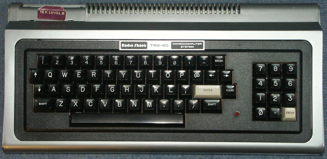
Connecting an Apple II keyboard to a computer with USB is surprisingly easy with a Teensy board. The Apple II uses an ASCII keyboard, which means that rather than returning scan codes, it returns a 7-bit ASCII value. This also means you can't read the state of modifier keys like shift or control independently. The Apple II keyboard in particular doesn't even support lower-case letters (though I've made a bit of a hack for this). They even re-use a couple alpha keys for other characters, so shift-P makes @ and shift-N makes ^. Other late 70s/early 80s home computers like the TRS-80 had a really simple layout like the Apple II's (though the TRS-80 had all four arrow keys but no Control key). I may have to try out adapting some other weird old home computers as USB keyboards -- the C-64 seems like it would be a good shape/size for that. (from afiler.com)
Arduino (Teensyduino) code is available at github.com/afiler/keyduino.
An arduino-based hangman prototype that uses a 16x2 LCD display, a potentiometer to scroll through the letters, button to select and speaker for sounds. Now to build a box!
So I got the sparkfun LSM303 breakout board working last night. Trouble is the I2C bus needs not higher than 1.8v logic levels to work properly.
The level shifter is capable of doing this, but it needs a 1.8v supply to operate, hence the white wire tapping it off the breakout board.
(The two yellow wires are due to the library pinout of the arduino nano board being bad)
Compass board:
www.sparkfun.com/products/9810
Level converter:
www.sparkfun.com/products/8745
Useful library for reading data:
Base board, without printed board layout. This is the pin set AFTER the chip has been bootloaded, otherwise you need pins running to the 3rd, 4th, and 5th pins up from the bottom right.
Arduino Academy, a 3-day summer programme for students in New Zealand, 7-9 July 2014. Catalyst IT was the organizer.
I know everyone has done this before. RFID and arduino that is. But looking at the example code it looks like the antenna is always in receive mode. I am not sure how this affects the life of the chip / reader but I thought of adding a way to detect human presence before activating the receiver.
I found some little IR heat detector (here: www.allelectronics.com/make-a-store/item/IRD-10/INFRARED-... and tossed together some analog read code and viola. Now when the IR detector detects over a certain variable heat temp it activates the RFID reader.
I will post the code and write up on my blog.
Elaborado sobre plástico flexible, este Arduino es un ejemplo de lo que se puede hacer siguiendo la técnica de David, autor del blog sewboard.cancamusa.net/
PCBs for a combined magnetometer and/or cloud detector.
Magnetic field measurements are taken from a Stefan-Mayer FLC100 sensor. Cloud detection is by measuring the 'sky' temperature. Low temperatures suggest clear skies and higher temperatures indicate the presence of cloud. A humidity sensor is also fitted to help predict the clear sky and cloudy sky temperatures. The Embedded Adventures lightning sensor module can also be fitted.
The sensor shield in intended to fit on my Calunium Arduino clone but it can also be used with an Arduino Mega2560. Design files, firmware and software are all open source (Creative Commons Attribution-ShareAlike 3.0 for hardware, GNU GPL v2 for software). github.com/stevemarple/AuroraWatchNet
Preliminary PCB layout for Calunium v2 Arduino clone using the ATmega1284P microcontroller.
Silk screen to be cleaned up after the component placement has been finalised.
For more information see blog.stevemarple.co.uk/.
the faint glow on the led is infra red light, invisible to the eye, but visible to the sensor in my camera.
Here I'm using the arduino to control the dvd player. I just need play/pause and the dv->out button.
Arduino clone with on-board DS1307 real-time clock. The layout is designed for easy assembly and maximum compatibility with the Arduino Uno, with additional functionality being compatible with the Arduino Mega2560. The auxiliary power connector and optional LM61 temperature sensor are not fitted on this board.
Eagle PCB design files available under Creative Commons Attribution-ShareAlike 3.0 Unported (CC BY-SA 3.0) licence, github.com/stevemarple/Calunium
A Sparkfun accelerometer rigged up to an Arduino which samples it and sends the data to the host computer. Fairly straightforward.
Arudino ethernet shield, use Microchip's ENC28J60 SPI ethernet controller --
open-source Arduino ethernet library is available at www.nuelectronics.com
Arduino LilyPad parts in preparation to being connected to Raspberry Pi. Red part is the 5/3V level converter that allows LilyPad to talk to Raspberry Pi
Testing wood-effect power lead
March 2012
For more on this, arduino stuff and other daft things see the "Making weird stuff" blog
A new version
A new version of the venerable Arduino Breakout Shield.
More info at make.rrrf.org/ab-1.4
Arduinoe shield pin layout on the Terasic DE0-Nano soc board.
Connection of 2 x spi lines and 1x I2C connection for the DE0-Nano soc board.
I'm using an old existing shield for the Arduino. The Terasic board has the right connection pins available. In addition there are 72 pins available for the user. I used 10 pins for the LCD display 4x20 char. This leaves 62 free pins. There is also an extra connector to read 8 analog signals, 12 bit accurate, 500Khz refresch rate.