View allAll Photos Tagged EngineeringMarvel
As dusk settles over Michigan, the Mackinac Bridge emerges as a monumental silhouette against the twilight. This photograph captures the stunning spectacle of the bridge at night, illuminated by a constellation of lights that trace its grand span across the Straits of Mackinac.
“Apollo 15 modified lunar module for the ninth manned Apollo crew. The members of the Apollo 15 prime crew are James B. Irwin, lunar module pilot; David R. Scott, commander; and Alfred M. Worden, Jr., command module pilot. Apollo 15 is the fourth lunar landing mission and the first to use the Lunar Roving Vehicle to traverse the lunar surface.”
The plume deflector under the near RCS quad is…not there, but the other two are. Other than that it’s great, to include the lunar surface sensing probes, correctly located/depicted.
Looks to be from the same base diagram, with ample, informative & useful callouts. Well done:
airandspace.si.edu/multimedia-gallery/5212hjpg
Credit: Smithsonian NASM
“Apollo 8 launched on December 21, 1968 and sent the first humans out of Earth's orbit. It carried Frank Borman, Jim Lovell and William Anders on the first launch of a Saturn V with a crew onboard on a mission to orbit the Moon 10 times before returning to Earth on December 27.”
The above is associated with NASA photo S-69-15558, a near equivalent image.
~7.675 x 10”, likely trimmed. Despite some varied minor flaws resulting from improper handling & minimal care, the photograph has retained nice gloss & detail.
The two diagonal lines to the left of the Saturn V are not photo emulsion artifacts, flaws or scratches, since they show up in other photographs of this and other Saturn V launches. I suppose they’re guy wires of some sort, supported by the one near the lower left being dark, in effect ‘silhouetted’ against the brighter billowing exhaust gases behind it, while the lighter one – which looks like it leads up to the crew access arm level – is due to it being illuminated by the F-1 engine plumes below.
WC 6588 flies solo on a train of coke empties over the St. Croix River on September 21, 1997.
RP reject, too much grain
“Three different rocket engines used to power the two Saturn vehicles are lined up at the National Aeronautics and Space Administration’s Michoud Assembly Facility. The Uprated Saturn I and Saturn V vehicles, the first stages of which are assembled at Michoud, are designed for use in Project Apollo, the United States’ manned lunar exploration program. The engines were built for NASA by the Rocketdyne Division of North American Aviation, Inc. Eight of the H-1 engines, (left) will develop 1.6 million pounds of thrust at liftoff for the Uprated Saturn I first stage. Five F-1 engines (center) will provide 7.5 million pounds of thrust for the Saturn V first stage. The J-2 engine (right) is used on both vehicles. Five J-2’s will give one million pounds of thrust to the second stage of the Saturn V and one J-2 will power both the third stage of the Saturn V and second stage of the Uprated Saturn I. The Uprated Saturn I will be used for astronaut training and testing the Apollo spacecraft’s systems, while the Saturn V will launch manned Apollo flights to the moon within this decade.”
Quite the lineup, eh?
FIFTY-FIVE (55)+ years ago!
Note that the F-1 does not have its nozzle extension attached.
Well-written, commensurate with the amazing quality, depth, richness & detail of the photograph.
Finally, too cool:
rocketreference.com/wp-content/uploads/2019/02/H-1-F-1-Co...

Credit: "ROCKETreference.com" website
“ARTIST: RICK GUIDICE PIONEER F SPACECRAFT IN ORBIT AROUND JUPITER”
NO……….AND……….NO ! ! ! ! !
I’m sorry, I can’t help it and I KNOW I shouldn’t be burning calories, popping blood vessels, raising my blood pressure, seeing red, etc., etc., but, damn, Damn, I Mean DAMN!!! REALLY???
I can ALMOST…NOT QUITE, but almost overlook the Guidice citation. He was producing a lot, if not most, of the conceptual Pioneer 10/11 Jupiter/Saturn & beyond artwork for the ARC during the early(?) – mid 70’s. However, wouldn’t the photograph/imagery, printing/publication department, section, office, supply/remedial writing room...clown factory…whatever it was called…dolt’s/dolts’ source work of this also have contained the artist’s signature, BEFORE THEY(?) would’ve cropped or otherwise removed it???
So, what, was Guidice was just an ‘educated’ guess? AGAIN, the bar was/is(?) EXCEEDINGLY LOW, so they get a pass on this.
And, it’s “Pioneer F” pre-launch/mission/flight, “Pioneer 10” upon launch/liftoff. A begrudging pass.
BUT - NOT - ON - THIS:
“…IN ORBIT AROUND JUPITER…”
Being a fairly historic ‘first’ & significant scientific/technical achievement, as far as space stuff goes, the media gave it plenty of coverage - providing desperately needed positive exposure. I remember such because I was really into it by that time. And as Pioneer neared Jupiter, IT WAS PUT OUT, OVER & OVER & OVER AGAIN that the spacecraft would ZOOM BY the planet, REALLY REALLY FAST, destined to eventually become the FIRST human-made object to LEAVE the solar system!!! You’d have to be living under - no, INSIDE a rock, beneath a glacier, in Antarctica, with earplugs & blinders on, to NOT know this…OR I suppose, work at NASA in whatever “office” responsible for releasing beautiful artwork of the aforementioned impending spectacular achievement.
To exacerbate this crap, as with way too many other instances of NASA photo-associated buffoonery, in lemming-like fashion, it’s propagated across the internet.
At least they stumbled upon the image & inadvertently posted it:
images.nasa.gov/details-ARC-1972-AC72-1281
See also:
solarsystem.nasa.gov/resources/708/pioneer-10-at-jupiter-...
On the bright side, it’s by talented NASA(?)/NASA-commissioned(?) artist Joseph “Chris” Chizanskos. A HUGE WIN+!!! Unfortunately though, having been inside the event horizon of NASA’s artist identification, acknowledgment, recognition & preservation blackhole, there’s nary a trace of him, other than the cursory info by way of the NASA Art Program thing from back then. Also, regrettably, there appears to be only a blip of a gentleman with that name having passed in 1973.
An absolutely beautiful image. I’m assuming the ominous dark area just above & behind the spacecraft is the Great Red Spot. Probably no greater resolution of it available at the time? I also like the visually evident actual physical texture of the image, I suppose picked up by whatever photo, scanning, illumination equipment used to capture the image. Bravo at least on that! So, reasonable to conclude it was outsourced then.
Although obscure as hell, at least there’s this:
collections.si.edu/search/results.htm?q=%22Joseph+Christo...
Credit: Smithsonian NASM website
“This photograph of Neptune was reconstructed from two images taken by Voyager 2's narrow-angle camera, through the green and clear filters. The image shows three of the features that Voyager 2 has been photographing during recent weeks. At the north (top) is the Great Dark Spot, accompanied by bright, white clouds that undergo rapid changes in appearance. To the south of the Great Dark Spot is the bright feature that Voyager scientists have nicknamed "Scooter." Still farther south is the feature called "Dark Spot 2," which has a bright core. Each feature moves eastward at a different velocity, so it is only occasionally that they appear close to each other, such as at the time this picture was taken. The Voyager Mission is conducted by JPL for NASA's Office of Space Science and Applications.”
photojournal.jpl.nasa.gov/catalog/pia01142
Credit: JPL Photojournal website
“An artist’s conception of the 1993 Hubble Space Telescope (HST) servicing mission shows an astronaut positioned to the left of the telescope preparing to install the Corrective Optics Space Telescope Axial Replacement (COSTAR). The optics were designed and built at Ball Aerospace and Communications Group, in Boulder, Colo., to significantly correct the spherical aberration in Hubble’s primary mirror.
The servicing mission is scheduled for launch aboard Endeavor in December. The artwork shown was created by Ball artist, Scott Kahler.”
Exquisite. Note the reflection of ‘ the cosmos’ on the closed aperture door of the engineering marvel…very nice touch.
Maybe because the stakes were so high, and Ball Corporation’s role in correcting the massive goof was critical, the company obviously went to great lengths to promote such, to include gorgeously illustrating what they were going to accomplish, accompanied by concise, intelligent & well-articulated descriptions. Mr. Kahler is obviously world class talent, and the caption writers seemed to actually comprehend what they were writing about. Unlike some other org…ah…uh...never mind. It is what it is. 😕
ALTHOUGH, they did misspell Endeavour. Oops! 😕
The jaw-dropping image was featured on the cover of the November 1993 issue of Sky & Telescope magazine - seen in the third image - suspended in zero-g near Astronaut Jeffrey Hoffman during the STS-61 mission. And, apparently, it was also featured on at least one t-shirt: 😉👍
Credit: “ART & ILLUSTRATION BY SCOTT KAHLER” website
The flown magazine cover:
www.icollector.com/Jeff-Hoffman-s-STS-61-Flown-Sky-and-Te...
Credit: iCollector.com Online Auctions website
Jeffrey A. Hoffman, the real deal:
en.wikipedia.org/wiki/Jeffrey_A._Hoffman
Credit: Wikipedia
www.nasa.gov/content/jeff-hoffman
Last, but NOT least:
aeroastro.mit.edu/faculty-research/faculty-list/jeffrey-h...
Credit: Massachusetts Institute of Technology/Department of Aeronautics and Astronautics website
"Jupiter and its four planet-size moons, called the Galilean satellites, were photographed in early March by Voyager 1 and assembled into this collage. They are not to scale but are in their relative positions. Startling new discoveries on the Galilean moons and the planet Jupiter made by Voyager 1 have been factored into a new mission design for Voyager 2. Voyager 2 will fly past Jupiter on July 9. Reddish Io (upper left) is nearest Jupiter; then Europa (center); Ganymede and Callisto (lower right). Nine other much smaller satellites circle Jupiter, one inside Io's orbit and the other millions of miles from the planet. Not visible is Jupiter's faint ring of particles, seen for the first time by Voyager 1."
The Voyager Project is managed for NASA's Office of Space Science by Jet Propulsion Laboratory, California Institute of Technology.
photojournal.jpl.nasa.gov/catalog/PIA01481
All above credit the JPL Photojournal website
A towering windmill stands tall against a moody, overcast sky, symbolizing the balance between nature and technology. The dramatic clouds add depth, while the sleek turbine blades capture the essence of clean, renewable energy. This image reflects sustainability, modern engineering, and the power of wind harnessed for a greener future.
This photo does not really do this justice as you need to be up much higher for a good perspective but the Tehachapi Loop is famous among railfans for it's unique construction. It was built in 1874 and is one of the busiest single track rail lines in the country. It is on the register as a California Historical Landmark and was a real engineering feat in its day.The loop is a.73-mile (1.17 km) spiral going thru the Tehachapi Pass in Southern California. On the track, the loop passes over itself to make the grade less steep.
A wonderfully composed shot of the May 25, 1966 rollout of the SA-500F Facilities Verification Vehicle (FVV) from the Vehicle Assembly Building (VAB).
Other than a black & white thumbnail remnant of this photo, no longer actually posted, I couldn’t find it anywhere. It’s a shame it’s previously been handled by clueless dolts.
But hey, a shitty photo…at high resolution…is better than none.
Posted ‘in honor’ of the rollout of the SLS/Orion/Artemis I conglomeration.
“"Rendezvous with CSM"
Almost exclusively available, published, posted, etc. (in color) from its lithograph source, from which I believe the above caption is taken.
Based on the perspective depicted, shouldn't it be "Rendezvous with LEM (ascent stage)"? Craig Kavafes…that's all that really matters.
The 'NASA-S-65-7186' equivalent of the photo bears the description of "LEM HEAD-ON DOCKING PICTURE".
I captured a stunning view of the Gateway Arch in St. Louis, Missouri. It was set against a backdrop of a clear blue sky. The sun glinted off the arch's sleek surface, emphasizing its elegant curvature and monumental scale. This architectural marvel stands at 630 feet and symbolizes the pioneering spirit and westward expansion of the United States. The simplicity and grandeur of the arch against the vast sky create a powerful image of aspiration and achievement.
Thank you for viewing! If you like this photo, don't forget to favorite and follow for more!
“Neil Armstrong and Edwin Aldrin will take off from the moon in the top part of their Lem, leaving the bottom part behind as their launch pad (1).”
Based on the stamped date, issued in conjunction with the flight of Apollo 11. And as part of the press release, labeled as photo no. 1. Photograph/image no. 2 of the press release is linked to below. Based on the appearance of the spacecraft, this was possibly the final/near final NAA/NAR rendering of the Apollo mission timeline ‘storyboard’.
As with those earlier renderings, I think it’s by Gary Meyer.
“APOLLO 6 ROLL OUT--------High-angle view of the Apollo 6 (Spacecraft 020/Saturn 502) stack and its mobile launch tower atop a crawler-transporter leaving the Vehicle Assembly Building on the way to Pad A, Launch Complex 39.”
Also:
www.nasa.gov/sites/default/files/thumbnails/image/9903402...

In color:
www.nasa.gov/sites/default/files/thumbnails/image/apollo_...

“LEM Cold Flow Test Site logo”
Is this “in-house” appealing or what?! I love it. It looks like it was created & rendered by one of the guys who took at least one art class in high school, or maybe the one semester/quarter at college.
For context, see/read my pointless observations accompanying the images linked to below.
If nothing else though, I’m at least connecting some obscure dots.
nyheritage.contentdm.oclc.org/digital/api/singleitem/imag...

Credit: “Cradle of Aviation Museum, Garden City, NY” website
Two versions of it are featured:
www.crewpatches.com/crewpatches_grumman.shtml
Along with the following remarks:
“An example of this patch appears on a vintage banner displayed at the Cradle of Aviation Museum at Long Island, New York.
Thanks to a letter discovered in the estate of Walter Schirra we now know that this patch was designed by a Grumman employee at the Bethpage plant in 1965. He intended it to be worn by personnel working on the LEM Propulsion systems there.”
Credit: “Crew Patches” website
An impressive photograph, ca. 1966/67 of the assembly line for F-1 rocket engine thrust chambers at North American Aviation’s Rocketdyne Division facility, Canoga Park, CA.
The number on the dolly is that of the engine on it, in this case '2053' & '2057' being visible.
And along those lines...excellent...as always:
heroicrelics.org/info/f-1/f-1-serials.html
Credit: Mike Jetzer/HEROIC RELICS website
The contemporary ‘official’ caption associated with the image:
“F-1 Assembly – Archive photo of the F-1 assembly line at Aerojet Rocketdyne’s Canoga Park, California facility.”
At:
www.rocket.com/sites/default/files/images/media/apollo50/...

Credit: Aerojet Rocketdyne website
Good Saturn engine reading:
“Excellent & rarely seen view of SA-500F Facilities Verification Vehicle stacking of the S-IVB stage, in the Transfer Aisle (I think) of the Vehicle Assembly Building (VAB), Kennedy Space Center. Two of the four areas of the SA-500F’s distinctive paint pattern are on display, comprised of the alternating black & white pattern of the forward skirt and the circumferential black (with white ‘cut-outs’) of the aft skirt. The latter being the most noticeable, even from a distance, due to its proximity to the kinda, sorta, semi- alternating, partially bi-level black & white scheme of the S-IVB aft interstage.
Additionally. Absolutely wonderful:
gwsbooks.blogspot.com/2019/07/500-f-beauty-queen-with-fee...
Credit: Wes Oleszewski/"Growing Up With Spaceflight" blog
“Aerial view of V.A.B. construction.”
An unassumingly exquisite photograph. The detail/resolution is phenomenal, let alone the subject matter. Just the overall enormity. Look at the massive girders laid out in front of the VAB - and the quantity - not to mention those already in place. The number, sizes & variety of cranes. The range of identifiable gorgeous vintage automobiles…everything from the Corvette front-and-center at the bottom, to Cadillacs, Nashes, Beetles & MORE. On the horizon to the left, you can even make out detail in the newly constructed Solid Motor Assembly Building (SMAB), part of the Integrate - Transfer - Launch (ITL) complex/facility, Cape Canaveral Air Force Station (CCAFS)! “COLBY CRANE” legible on the housing of the Launcher Umbilical Tower (LUT) hammerhead crane on the right. And more.
The body of water to the left of & behind the VAB will become the turning basin.
Pretty awesome. Nineteen Sixty-Four (1964).
“LEM MOCK-UP—A full scale mockup of the Apollo Lunar Excursion Module is shown at the Lunar Topographical Simulation Area. Astronauts and engineers will use the vehicle and area for simulations and training exercises.”
Above per the verso of one of the NM Museum of Space History photos linked to below.
I think the LEM was emplaced on the Lunar Topographical Simulation Area some time during 1965, and this certainly looks like early/initial photographic documentation after such.
It looks like there's someone inside. What looks like a right hand can be seen at the 10:30 clock position of the forward egress/ingress hatch.
Finally, what LEM is this? Is it technically a mock-up, i.e. an "M-" series? Or, although I think less likely, a training model, i.e. "TM-" series?
The Apollo Program Summary extract linked below, unfortunately, doesn't help, me at least.
In lieu of comparative photographs (other than the one following), along with well-founded skepticism and doubt associated with NASA photographic record keeping & identification, I’ll foolishly go out on a limb and call this S-IC-3…being hoisted into position or removed(?) from the S-IC Test Stand/Building 4670, Marshall Space Flight Center (MSFC), possibly in October 1966.
In support of my above, I submit the following weak evidence:
history.nasa.gov/MHR-5/part-7.htm
Specifically, the following passage:
“After successful completion of post-manufacturing checkout at the Michoud Booster Checkout Facility, the S-IC-3 stage left Michoud on September 23 and arrived at MSFC on October 1. Unloading operations began on October 3, and on that same date workmen erected the stage in the test stand. ³²⁵
325. MSFC Press Release No. 66-223, Sept. 29, 1966.”
Even more specifically, this image – it being the ‘smoking rocket’:
history.nasa.gov/MHR-5/Images/fig317.jpg

HOWEVER, odds are far greater that it’s S-IC-T, due to the fact that it was static fired multiple times in the test stand. Per Mike Jetzer’s superlative “HEROIC RELICS” website:
“A total of 18 tests were performed with the S-IC-T stage at MSFC. The first three flight stages were also static-fired in the stand, with S-IC-1 undergoing two tests and S-IC-2 and S-IC-3 each being fired once. S-IC-4 and subsequent were tested at the MTF.”
At:
heroicrelics.org/msfc/test-stand-s-ic/index.html
ALTHOUGH, what little photographic evidence I’ve found of the purported S-IC-T at the MSFC S-IC test stand, of both supposed emplacement & removal, none have evidence of thrust chambers installed.
FINALLY, the outward appearance of the S-IC probably offers a clue as to its identification, Unfortunately though, I can’t keep up with the different paint schemes of the Saturn V’s, which seemed to have been changed, at different locations, during different times of the manufacturing/testing process, and where/when/if the U.S. flag decals were applied, along with what font “USA” decal was applied. So I suppose my final determination should actually be: who the f**k knows.
“Voyager 2 obtained this high-resolution color image of Neptune's large satellite Triton during its close flyby on Aug. 25, 1989. Approximately a dozen individual images were combined to produce this comprehensive view of the Neptune-facing hemisphere of Triton. Fine detail is provided by high-resolution, clear-filter images, with color information added from lower-resolution frames. The large south polar cap at the bottom of the image is highly reflective and slightly pink in color; it may consist of
a slowly evaporating layer of nitrogen ice deposited during the previous winter. From the ragged edge of the polar cap northward the satellite's face is generally darker and redder in color. This coloring may be produced by the action of ultraviolet light and magnetospheric radiation upon methane in the atmosphere and surface. Running across this darker region, approximately parallel to the edge of the polar cap, is a band of brighter white material that is almost bluish in color. The underlying topography in this bright band is similar, however, to that in the darker, redder regions surrounding it. The Voyager Mission is conducted by JPL for NASA's Office of Space Science and Applications.”
Also:
“Voyager 2 image showing the southern hemisphere of Triton. At 2,700 km diameter, Triton is Neptune's largest satellite. This image was made using about a dozen Voyager 2 frames. The large, pinkish colored south polar cap is at the bottom of the image. North of the cap the surface is generally darker and redder in color. This area exhibits a plethora of unusual morphologic features, including the long lineations at the center of the frame.”
With the image, from/at:
nssdc.gsfc.nasa.gov/imgcat/html/object_page/vg2_p34764.html
Credit: NSSDCA website
And:
“Voyager 2 passed by Triton about 5 hours after skimming within 5000 kilometers (3000 miles) of the cloud tops of Neptune. Triton is only slightly smaller than Earth’s Moon and is one of the most unusual objects encountered during all the Voyager planetary flybys. This image is a digital mosaic of 12 individual images, with color information added from lower-resolution frames. The large south polar cap at the bottom of the image is a slowly evaporating layer of frozen nitrogen. The dark streaks on the polar cap are probably deposits resulting from the expulsion of frozen nitrogen that suddenly changed to the vapor phase, essentially a nitrogen eruption. Voyager data showed that Triton is extremely cold (daytime temperature of 37 K, or –400°F), extremely bright (reflecting nearly 100% of the sunlight incident upon it), and has a very tenuous atmosphere of nitrogen and methane (with a surface pressure 10 millionths of Earth’s atmosphere at sea level). The darker, slightly redder color beyond the polar cap may result from radiation effects on methane included within the ice. The ridges and depressions visible away from the polar cap are probably due to the deformation of water ice. Triton is essentially the same size and density as Pluto so it is possible that the surface of Pluto may look somewhat like Triton, but Pluto remains the only planet not yet visited by a spacecraft.
Mosaic of Voyager 2 images (Press Release P-34764).”
Also with the image, from/at:
www.lpi.usra.edu/publications/slidesets/ss_tour/slide_38....
Credit: LPI website
The Golden Gate Bridge glows orange against the predawn darkness, its iconic towers and suspension cables illuminated while fog wraps around the Marin Headlands beyond.
Photographed from Twin Peaks looking west, this panoramic view captures San Francisco in that liminal moment between night and day when the city's lights still sparkle but natural light begins painting the sky in subtle gradients of blue and pink.The bridge itself commands the middle distance, its distinctive International Orange color standing out even in low light thanks to the decorative lighting that traces its towers and cables. Those twin towers rising 746 feet above the water have become synonymous with San Francisco itself, perhaps the most photographed and recognizable bridge in the world.
Opened in 1937 after four years of construction, the Golden Gate Bridge was an engineering marvel that many said couldn't be built—spanning 4,200 feet across the strait connecting San Francisco Bay to the Pacific Ocean, withstanding powerful currents, deep water, and frequent fog.
The foreground reveals San Francisco's residential fabric spreading across the city's western neighborhoods. This elevated vantage from Twin Peaks—roughly 900 feet above sea level—allows you to see the gridded street pattern, the mix of housing types, and the tree canopy that softens the urban density. The Richmond and Sunset districts dominate this western side of the city, their orderly blocks of single-family homes, small apartment buildings, and neighborhood commercial corridors representing post-earthquake development and the city's mid-century suburban expansion within city limits.
Look at how the city lights create different patterns. Bright commercial zones—likely the Richmond District's Geary Boulevard and the Sunset's Irving Street—cut horizontal paths through residential areas where warmer, more diffuse lighting suggests homes and local businesses. The Presidio's darker areas on the left preserve the former military base's forest and open space, while Golden Gate Park's dark band running through the middle of the frame shows how that three-mile-long urban forest creates a natural break in the city's development pattern.
The atmospheric conditions are quintessentially San Francisco. That thick bank of fog sitting over the Marin Headlands and threatening to spill through the Golden Gate represents the marine layer that gives the Bay Area its temperate climate and famously unpredictable weather.
The bridge's towers emerge from the fog like sentinels, while the low cloud deck above creates a muted sky that will likely give way to sunshine or remain overcast depending on how that marine layer behaves over the next few hours.The bay waters beyond the bridge show as a dark band separating San Francisco from Marin County.
This strait has always been treacherous—strong tidal currents, cold water temperatures, and frequent fog made navigation challenging long before the bridge existed. Ships entering San Francisco Bay had to time their passage carefully, and countless vessels met disaster on the rocks.
The bridge transformed regional transportation, connecting San Francisco to the North Bay and beyond, enabling suburban development in Marin and Sonoma counties that fundamentally reshaped the region's geography.
From this elevated perspective, you can appreciate San Francisco's unique urban form. This is a city that refused to be limited by its hilly topography. Those neighborhoods spreading across the western slopes represent generations of San Franciscans who carved streets into steep hillsides, built homes on challenging lots, and created communities in every available space. The density is impressive—this is one of America's most densely populated cities—yet the scale remains human. Few high-rises interrupt the horizon, preserving view corridors and maintaining neighborhood character.
The lighting in this photograph creates layers of depth and atmosphere. The cool predawn sky gradates from darker blue overhead to lighter tones near the horizon, while the warm city lights provide contrast and detail in the foreground. The bridge's orange glow becomes the visual anchor, drawing the eye across the frame while the scattered lights of Marin communities beyond suggest the broader metropolitan region connected by this single span.
San Francisco's relationship with the Golden Gate Bridge is complicated. It's simultaneously the city's most beloved symbol and a barrier some never cross. The bridge connects but also divides—creating a psychological boundary between city and suburbs, between urban San Francisco and the less dense communities to the north.
For tourists, it's a must-see attraction. For locals, it's infrastructure—a commute route, a running path, a beloved but familiar landmark that becomes invisible through daily exposure until you see it like this, at dawn, and remember why people photograph it obsessively.
“APOLLO 6 ROLL OUT-----The Apollo 6 (Spacecraft 020/Saturn 502) stack and its mobile launch tower atop a crawler-transporter moving from the Vehicle Assembly Building toward Pad A, Launch Complex 39.”
The ENTIRE Apollo PROGRAM: Over-budget & on-time.
SLS (JUST the ROCKET): Way way way over- budget & way way way late.
Sign of the times.
Credit: Internet Archive website
www.youtube.com/watch?v=y3KEhWTnWvE
Credit: YouTube/Ahmad F Elyan
“Command Module 107 and Service Module move from Chamber “L” to work stand. Command Module 108 in background.”
And what appears to be another, possibly later ‘official’ description:
"Apollo Command and Service Modules scheduled for manned landing mission on the Moon cross paths in the Manned Spacecraft Operations Building at KSC. The meeting occurred when the CSM for Apollo 11 was being hoisted out of a test chamber and the CSM for Apollo 12, which recently arrived at KSC, was getting its initial checkout in the aisle."
And/or:
“Apollo command and service modules scheduled for manned landing missions on the moon cross paths in the Manned Spacecraft Operations Building at the spaceport. The meeting occurred last night when the CSM for Apollo 11 was being hoisted out of a test chamber and the CSM for Apollo 12, which recently arrived at Kennedy Space Center, was getting its initial checkouts in the aisle. Apollo 11 is scheduled for the first manned lunar landing mission this summer.”
According to a knowledgeable individual at the collectSPACE website, LM-5 & LM-6 were also in the MSOB at this time.
Unexpectedly - the latter, along with the image - are at the following link. Surprisingly, against all odds, they managed to find the image, orient it correctly and then somehow even mustered the competencies & effort to post it for the 50th anniversary of Apollo 11:
A wonderful ca. 1966-69 NASA artist’s concept depicting LM ascent stage liftoff from the moon.
Fortunately, the signature is visible, and it’s by Lois A. Smith! A WIN!
I believe the depiction of the lunar terrain, and of course the LM, may allow me to identify other works by her. If so, outstanding.
I didn’t know Epson made photographic paper. And it’s a heavier weight than I would’ve expected. An unexpected & pleasant surprise.
A gorgeous, even if somewhat over-the-top depiction of, what to me looks a lot like a Hubble servicing mission. Note the non-tethered MMU-wearing Astronauts, representing the heady & all too cavalier vision of what future EVAs would look like. Note also that the orbiter is without the Remote Manipulator System arm…hmm.
Disappointingly/per SOP, the NASA photo whoevers botched the layout of the image; to include the ‘landscape’ orientation and the excessive cropping, lopping off half of the shuttle & half of HST’s aperture door and, in the process, the artists’ signatures.
The complete image was featured on the cover of the 2015 Winter Issue of “Pulsar”, the bi-annual newsletter of the International Association of Astronomical Artists (IAAA), at:
iaaa.org/CygnusX1/wp-content/uploads/2021/01/Pulsar-2015-...
Credit: IAAA website
Within the newsletter, per the artist responsible, Rick Sternbach:
“Science Digest, Astronomy, and Sky & Telescope all featured this painting of the HST done as a collaboration between myself and Don Dixon. Extensive use of airbrush and acrylics, a similar rendering style, and detailed CAD drawings from Lockheed Sunnyvale allowed us to produce this orbital view a few years before Hubble was launched.”
With a flipped "order of billing", reference to it being Perkin-Elmer copyrighted & dated 1984. ¯\_(ツ)_/¯:
www.cosmographica.com/spaceart/Technology/index.html#img=...

Credit: Cosmographica website
Regardless, as a card-carrying member of IAAA’s peanut gallery - if you have even the slightest interest in this type of artwork - I highly recommend taking a look at the following gallery. I can attest that IAAA members are conscientious & consummate professionals constantly striving to create meaningful works:
“Pad 39A MSS pullback from 503 Saturn plus xenon lamps affect off pad area.”
A stunning photograph, despite the color shift & emulsion artifacts, of THE rocket of ALL rockets - the Saturn V.
The historic flight of Apollo 8 commenced the following day, December 21, 1968.
Nineteen Sixty Eight…1968.
As of this ‘writing’, that’s nearly this many years ago:
IIIII IIIII IIIII IIIII IIIII IIIII IIIII IIIII IIIII IIIII III
That’s A LOT.
“SPS CONSTRUCTION: SECOND PASS”
No signature. Craig Kavafes?
Fortunately, the image is in Fig. 2 of the following, a 1980 paper entitled “SPECIFIC SPS CONSTRUCTION STUDIES: CONSTRUCTION TASKS-CONSTRUCTION BASE”, by Ronald W. McCaffrey, Grumman Aerospace Corporation, Bethpage, N.Y.
The scale & enormity of the proposed concept is mind boggling…no wonder it was never built, despite the envisioned utopian energy end state.
“ABSTRACT
This paper discusses a concept for building the 5000 MW reference Solar Power Satellite in earth orbit, based on recent work performed for NASA/JSC under contract to Boeing, on the SPS System Definition Study, and on related work performed under Grumman IRAD.
INTRODUCTION
Several concepts have been recently described on how to build the Solar Power Satellite (SPS) in space. These concepts entail fabrication and assembly of the entire satellite in geostationary earth orbit (GEO), at 35,800 km altitude, as well as partial construction at an intermediate low earth orbit (LEO) followed by final assembly in GEO. A concept for building the entire 5000 MW reference satellite in GEO is discussed below. Construction base operations needed to produce one SPS every six months are described and areas for near term technology development are identified.
GEO CONSTRUCTION BASE
The GEO Base concept shown in Fig. I was developed to build the 5000 MW reference SPS system, which uses silicon solar cells with no concentration. This 4 Bay End Builder construction base was selected for further definition in the Phase 2 study because it offered greater production capability than other concepts investigated in Phase I. The GEO construction base is configured to avoid free flying facilities and/or assembly methods. As a result, the base has contiguous facilities for concurrent assembly and subsequent mating of the satellite energy conversion system and its power transmission antenna.
The overall base is 3.44 km wide x 3.65 km long x 0.9 km deep. The base structure serves as an assembly jig which houses the required construction equipment and supports the emerging satellite during all phases of construction. The top deck of the GEO base, level J, provides facilities for cargo docking/unloading and distribution, crew quarters, command and control operations, orbital transfer vehicle (OTV) docking and servicing, and SPS maintenance support complex. Base electrical power and flight control subsystems are also provided so that all work facilities and crew support facilities can operate, as needed.
GEO CONSTRUCTION OPERATIONS
The personnel needed to activate the 4 Bay End Builder Construction Base must travel first by means of the Shuttle to LEO and finally, by means of an orbital transfer vehicle (OTV) which operates from the LEO base.
The 4 Bay End Builder Base assembles the 5 GW reference Solar Power Satellite entirely in geosynchronous orbit, as shown by the construction sequence shown in Fig. 2.
[OF WHICH THE POSTED PHOTO IS A PART OF]
The 8 bay wide satellite energy conversion system is constructed in two successive passes on one side of the base, while the microwave antenna is assembled on the other side of the base. During the first construction pass, the GEO base builds one-half of the energy conversion system, a 4 bay wide strip by 16 bays long. When this part of the satellite has been constructed, the base is indexed back along the edge of the structure to the first end frame. During the second construction pass [THE POSTED PHOTO], the remaining 4 bay wide strip is attached directly to the assembled satellite systems. Throughout the construction operation, SPS construction materials and components will be delivered by large electrical orbital transfer vehicles (EOTV). These vehicles will station-keep at least 1 km away, while special cargo tugs transfer material pallets. GEO base crews will, of course, also be rotated as needed. At the end of the second pass, the base is then indexed sideward to mate the antenna with the center line of the energy conversion system. After final test and check out, the base separates from the satellite and is transferred to the next orbital position for SPS construction.
The reference scenario requires that one 5 GW satellite is to be constructed every six months for 30 years. In order to carry out this program, nearly 450 space workers would be needed on two daily shifts (10 hours each) to perform construction, base support, maintenance, safety and base management operations.
BASE CONSTRUCTION SYSTEM
The end builder construction system described above uses ten synchronized beam machines to automatically fabricate continuous longitudinal beams for the energy conversion system. Lateral and diagonal members of the structural assembly are fabricated with three mobile beam builder substations. The assembly sequence, as shown in Fig. 3, begins with assembly of the first end frame and its attachment to the longitudinal members. This frame is automatically indexed away as the synchronized beam builders fabricate the required length of longitudinal beam to complete the structural bay. During these operations, solar array blankets and power busses are installed in parallel. For example, Fig. 4 shows how the solar array blankets might be temporarily anchored to the base so that they can be automatically deployed during longitudinal beam building operations. The illustration also shows two cherry pickers prepared to handle and connect opposite ends of a 667.5 m solar array support beam to the SPS frame after it emerges from the 12.7 m beam builder.
NEAR TERM TECHNOLOGY EMPHASIS
Constructing the large skeletal structure of the energy conversion system (5.35 km x I0.78 km x 0.47 km), including the installation and check out of its subsystems, will not be an easy task. While plausible concepts have been derived and limited development work has been started on auto-fabrication, a great deal of additional analysis and technology development work needs to be done before we can have confidence in the practicality of this process. For example, future dynamic analysis of the satellite construction process may show that some techniques can impose stringent load conditions on the elements of the satellite, while other techniques do not. As the reference SPS concept matures, all aspects of the construction approach must be analyzed further and periodically re-examined by considering technology issues related to the satellite design, orbit construction location, base facilities, crew and operations. These efforts should also be supported by laboratory investigations of SPS construction issues related to structural fabrication and assembly, construction support and subsystems assembly methods. This effort should be focused on developing technology which can lead toward SPS beam builders, SPS beam handling, subsystem assembly, mating of large space structures and techniques for deploying/installing SPS non-structural subsystems. Subscale prototype demonstrations should be used, wherever practical.”
At:
ntrs.nasa.gov/citations/19820014858
Additional pertinent reading, to include the image:
nss.org/wp-content/uploads/SSP-Boeing-CR160480-1979-Phase...
Credit: NSS website
"Apollo-4 Configuration"
"Sta" refers to station numbers...which appear to be a standardized bottom-to-top linear reference system, in inches, of the launch vehicle’s ‘planes’ of attachment(?), separation(?) and (thanks to Mike Jetzer)…gimbal.
I think I've also seen station numbers associated with/to levels/points on either the Mobile Service Structure (MSS) or Launcher Umbilical Tower (LUT). Maybe even both? If so, reasonable to assume they correspond with those of the vehicle??? Then again, it may just be a concocted memory on my part.
Fortunately, and commensurate with the superb site it is, the following excerpt, along with additional graphics, sheds light on the ‘mystery’:
“The station numbers are at right. Marshall Space Flight Center station numbers are in inches and are defined such that station 100 is the gimbal plane of the engines. This scheme seems to have started with the Jupiter missile (the first ABMA missile with an engine with gimbal capability; the Jupiter's S-3D engine was 100 inches tall from the exit plane to the gimbal plane) and continued on up to the Saturn V. This leads to the somewhat unusual need, in the case of the much-larger F-1 engine, for negative station numbers.”
At:
heroicrelics.org/info/saturn-v/saturn-v-general.html
heroicrelics.org/info/saturn-v/saturn-v-general/saturn-v-...
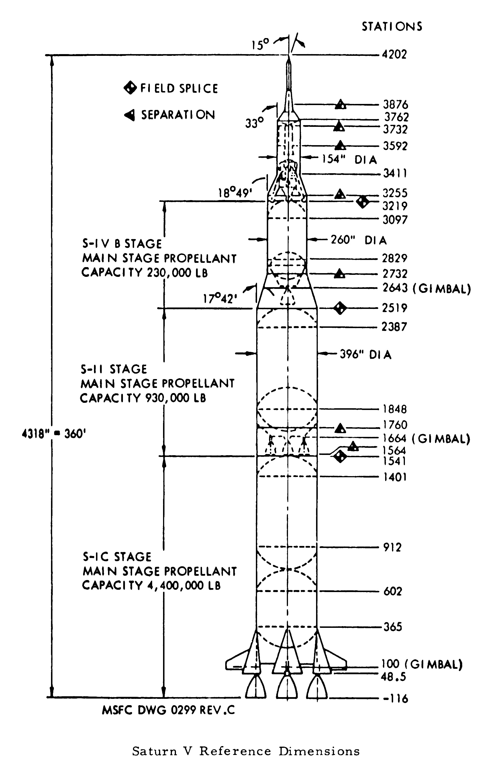
Both above credit: Mike Jetzer/heroicrelics.org
If correct, which I have no reason to doubt, how bizarre…to continue the “tradition”. There surely must’ve been some interesting history & background for its 'continuation'. So, station numbers seem to be attributed to MSFC. I don't get it.
Also, although I've found "field splice" in various NASA documents, it still doesn't help me understand or visualize it. So, I guess it's "duh" on my part.
SLS my Artem-ass. 😜
“STS-31 onboard photo – HST deployed”
A rarely seen image of the initial deployment of the Hubble Space Telescope (HST). Taken from one of the aft-facing flight deck windows, the close proximity & dramatic perspective indicates it to have been taken early in the deployment process.
Note the prominent dish of one of the two still retracted high-gain antennas, along with the still retracted & rolled up solar arrays along either side.
Finally, note also the abundance of handrails on HST, to facilitate the unprecedented human maintenance of the engineering marvel.
I hope so, very much:
www.nasa.gov/feature/goddard/2022/nasa-spacex-to-study-hu...
Official Grumman Aircraft Engineering Corporation (GAEC) photo of the ubiquitous (at that time) and coveted (to this day) desktop model of the Lunar Excursion Module, manufactured by Precise Models, Elyria, Ohio. Appropriately enough, where I grew up.
“This image was returned by the Voyager 2 spacecraft on July 3, 1989, when it was 76 million kilometers (47 million miles) from Neptune. The planet and its largest satellite, Triton, are captured in the field of view of Voyager's narrow-angle camera through violet, clear and orange filters. Triton appears in the lower right corner at about 5 o'clock relative to Neptune. Recent measurements from Voyager images show Triton to be between 1,400 and 1,800 kilometers (about 870 to 1,100 miles) in radius with a surface that is about as bright as freshly fallen snow. Because Triton is barely resolved in current narrow-angle images, it is too early to see features on its surface. Scientists believe Triton has at least a small atmosphere of methane and possibly other gases. During its closest approach to Triton on August 25, 1989, Voyager should provide high-resolution views of the moon's icy surface and reveal whether Triton's atmosphere has clouds. JPL manages the Voyager Project for NASA's Office of Space Science and Applications.
pg. 57-5”
The cited page number possibly of some NASA/JPL documentation on which the image was featured?
photojournal.jpl.nasa.gov/catalog/PIA01491
Credit: JPL Photojournal website
“When one of the two SR-71B trainers, no. 61-7957, was lost on approach to Beale AFB on 11 January 1968, a replacement was built. Designated SR-71C, it was built from the aft fuselage of YF-12A no. 60-6934 and the SR-71A static test model from Lockheed. This aircraft never lived up to the usability of the SR-71B as it had irregular maintenance procedures and its aftermarket construction caused the aircraft to fly in a constant yaw, which gave it its nickname "The Bastard." Consequently, the SR-71C was used on a limited basis from 1969-1976.”
Above at/from:
www.sr-71.org/photogallery/blackbird/17981/
Credit: “SR-71 Online: An Online Aircraft Museum” website
Who knew?
Did you?!
I didn’t!!!
Also, amongst plenty of others:
avgeekery.com/there-can-be-only-one-the-saga-of-the-only-...
Credit: “AVGEEKERY.COM” website
Finally. The quote from Lt Gen William Campbell (Ret) would seem to somewhat dispel the perpetual problematic nature of the aircraft:
Credit: Habu.Org (The Online Blackbird Museum) website
One of few photographs of this ‘unicorn’, taken ca. 1969 or later.
1965 cut-away diagram of the Lunar Excursion Module Ascent Stage, representing the 'final' version. Note that "Excursion" was still part of the nomenclature as of the printing of the photo.
Note the Major Matt Mason-like space suit worn by the Astronaut. Sort of looks like an A2-L and/or immediately subsequent.
“This picture shows a region of the southern hemisphere extending from the Great Red Spot to the south pole. The white oval is seen beneath the Great Red Spot, and several small scale spots are visible farther to the south. Some of these organized cloud spots have similar morphologies, such as anticyclonic rotations and cyclonic regions to their west. The presence of the white oval causes the streamlines of the flow to bunch up between it and the Great Red Spot.”
Above at/from:
photojournal.jpl.nasa.gov/catalog/PIA00372
Credit: JPL Photojournal website
And…here it comes! At the “NEW” & “IMPROVED”, THE ONE & ONLY “NASA Image and Video Library” website! Oh, wait one, ONE of these things is NOT like the others.
PATHETIC, although consistently so, at least:
images.nasa.gov/details-ARC-1979-AC79-7072
From the estate of Eric Burgess, thus possibly featured as ‘Figure 5-18’ in one of his many books.
“Artist’s concept of Pioneer over Jupiter’s Red Spot.
Man will reach out beyond Mars to take the first close look at the planet Jupiter on the mission of the unmanned Pioneer F spacecraft, to be launched by the National Aeronautics and Space Administration from Cape Kennedy, Fla., between Feb. and March 1972. The trip to Jupiter will last less than two years, for most launch dates, with most arrival times before Dec. 31, 1973. Jupiter is a spectacular planet. It appears to have its own internal energy source and is so massive that it is almost a small star. It may have the necessary ingredients to produce life. Its volume is 1,000 times that of Earth, and it has more than twice the mass of all the other planets combined. Striped in glowing yellow-orange and blue-gray, it floats in like a bright-colored rubber ball. It has a huge red “eye” in its southern hemisphere and spins more than twice as fast as Earth. Pioneer’s 13 scientific experiments are expected to provide new knowledge about Jupiter and many aspects of the outer solar system and our galaxy. It will return the first close-up images of Jupiter, and will made the first measurements of Jupiter’s twilight side, never seen from Earth.”
From the estate of Eric Burgess, and possibly featured as figure 3-3(a) in an unidentified publication by him.
Although disappointingly, wrongly, yet as expected, acknowledged nowhere within the following document, I’m quite certain that this beautiful work is by Rick Guidice. As the title/header image for chapter 4, along with the title/header artist’s concepts within the publication confirmed to be by Mr. Guidice, a reasonable extrapolation. Besides, it was probably contractually agreed to by Mr. Guidice & NASA.
In color:
images.nasa.gov/details-ARC-1972-AC72-1354
Along with others. Always exceptional:
e05.code.blog/category/nasa-un-crewed-programs/pioneer/
Credit: numbers station blog
“Saturn SA-1
Open house – 1961
Manufacturing Engineering Div
Marshall Space Flight Center
Huntsville, Alabama”
The above is beautifully handwritten by pen, in cursive, on the verso. Obviously by someone intelligent, articulate, possessing excellent penmanship and MOST importantly, ‘in the know’. Therefore, SA-1 it is. Which is what I assumed, despite not a single bit of documentation, etc., that I’ve come across that clearly states such.
Several (of the few) sources have namby-pamby descriptions/wording of the iconic views of the rocket in this horizontally ‘assembled’ & displayed state – that can be interpreted to imply that it’s SA-1…kinda/sorta/maybe.
But, if it's not...oh well. At least I made a legitimate attempt. Which is more than I can say about those whose responsibility it was/should’ve been.
The “Space Launch Report” website, the LONE site which actually referred to it as SA-1 is history, the domain having expired. A HUGE loss for someone such as myself, or anyone else conscientiously attempting to accurately catalog & preserve NASA photographic history…which obviously exceeds their ability/capability.
The caption affixed to another very similar black & white NASA-MSFC issued photograph, date stamped “JUL 7 ‘61” reads as follows:
An estimated 45,000 to 50,000 persons streamed through the George C. Marshall Space Flight Center, NASA, during the Center's "Space Day" open house, commemorating the first anniversary of the establishment of the Center. In this picture, visitors view a three-stage Saturn C-1 in an assembly hangar. This rocket is identical to the first Saturn which will be launched later this year.
And finally, from the May 1974 iteration of “AN ILLUSTRATED CHRONOLOGY OF THE NASA MARSHALL CENTER AND MSFC PROGRAMS 1960-1973”:
An estimated 45,000 to 50,000 "Space Day" visitors attended MSFC's first open house on July 1. Attending were such national figures as the NASA Administrator James E. Webb; the Director of NASA Launch Vehicle Programs, Maj. Don Ostrander; and numerous other national state, and local dignitaries. Most of the visitors observed one of the four Saturn H-1 engine static firings during the day.”
A rare, delightful unicorn containing valuable (IMHO) historical information, and brimming with wonderful nostalgia. And it’s on that exquisite super-duper smooth glossy film-like ‘paper’. You really gotta see/feel it to appreciate it…seriously.
The two exaggeratedly rectangular, tripod-mounted cameras (to the lower right) look to be, to me, Polaroid Pathfinders (110/110A/110B/120?), or 800’s maybe? It even looks like the fellow is either loading film or about to pull an exposed ‘shot’ out of one of them.
camerapedia.fandom.com/wiki/Polaroid_Pathfinder
Credit FANDOM/CAMERAPEDIA website
Finally, note the congregation of primarily males, their attention focused on the fetching young lady wearing the “SPACE(?) PRINCESS” sash. And to her right appears to be a queen and another sash-wearing “SPACE(?) PRINCESS”. So, obviously, the queen and her court…possibly from an on-site(?) MSFC parade earlier in the day.
“The Apollo 10 Saturn V space vehicle rushes skyward from the Kennedy Space Center’s Launch Complex 39B today at the start of the lunar orbit mission. The 363-foot-high space vehicle generated a liftoff thrust of 7.7 million pounds.”
“Rushes”??? Not yet…later. First time I’ve ever read that verbiage. At least it’s not “blasts off” and even reveals a noble albeit mediocre attempt at dramatic flair.
This is by far the best image - in a physical photograph of this event - that I’ve come across.
[And to be clear, I'm not boasting, it's a fact. Nearly all others I've seen, to include my others, are as I describe...IMHO.]
Although the launch was indeed under cloudy/overcast conditions, to me it also seemed that nearly all period/vintage “A KODAK PAPER” (and non-water marked prints) of this were really yellowed, along with a low contrast, dull, dingy appearance. This one breaks the mold.
“Top of 31-foot-long diffusers fit around Saturn S-IV engine nozzle bells in static test stand at the Douglas Aircraft Company’s Sacramento installation. Prior to ignition of engines, air is evacuated from diffusers, simulating the near-vacuum conditions in which S-IV engines will be ignited in outer space. Douglas Missile & Space Systems technician is working on one of six RL-10A3 engines suspended from battleship tank. First static firing will occur shortly.”
If, like me, you’ve tossed & turned many-a-night wondering how in/on the world (literally) do you realistically test fire a rocket engine that’s designed to operate exclusively in a near vacuum/vacuum, and the above merely whets your appetite, we’re in luck thanks to the following:
Douglas Missile & Space Systems Division’s “ALTITUDE SIMULATION IN SATURN SIV STAGE TESTING/Douglas Paper 3172”, at:
libarchstor2.uah.edu/digitalcollections/files/original/20...
Credit: UAH Archives and Special Collections/Digital Collections website
We have:
“ABSTRACT
Altitude Simulation in Saturn SIV Stage Testing
The Douglas Aircraft Company has been involved in testing the Saturn SIV stage at the Sacramento Test Center for the past two years. The propulsion system for the SIV stage consists of six (6) Pratt & Whitney Aircraft Company rocket engines which are designed specifically for high altitude start and operation. During static firing tests of this engine at sea level, a steam jet ejector in combination with a diffuser, are used to simulate altitude conditions. The intent of this paper is to examine the performance of this altitude simulation system, and to discuss problems encountered in making it operational.
--------------------
The Douglas Aircraft Company has been involved in testing the Saturn SIV stage at the Sacramento Test Center for the past two years. The SIV is an upper stage of the National Aeronautics and Space Administration's Saturn Space Vehicle. A later version of the Saturn Space Vehicle is programmed to launch an Apollo to the moon. The propulsion system for the SIV stage consists of six (6) Pratt & Whitney Aircraft Company RLIOA-3 rocket engines capable of generating a total of 90,000 pounds thrust at altitude. These engines were designed specifically for high altitude start and operation and, therefore, require an altitude simulation system to permit sea level static testing. The normal starting altitude of the Pratt & Whitney RLlOA-3 engine, when used as part of the SIV stage, is approximately 240,000 feet, where the expected absolute pressure is 0.17 psia.
It is not required that this low a pressure be obtained for sea level testing, however. The engine requires sufficient pressure drop between the liquid oxygen pump inlet and the combustion chamber to attain a pre-start flow of liquid oxygen. This flow must be sufficient to cool the pump so that stall free acceleration and mainstage operation can be achieved. The time interval required, as well as the quality and quantity of liquid oxygen required, had to be established during static testing. Even more basic, however, is the requirement that the high expansion ratio (40:1) thrust chamber bell be operated without flow separation. If the engine were operated at sea level back pressures, separation would occur, with attendant structural and performance degradation. The engine bell construction was intended for altitude operation and thus not designed to withstand the high loads which would be encountered in sea level operation.
The total altitude simulation system utilized in the SIV stage static testing is comprised of four elements: (1) the diffusers, (2) the eiectors, (3) the accumulators, and (4) the steam boilers and feed water system.
The diffusers are attached to each of the six engines with a flexible seal, and are closed at the opposite end by blow-off doors. In this configuration they serve as a vacuum chamber to provide low ambient pressures (less than 0.9 psia) in the forty-five (45) second period up to and including engine ignition. By controlling the engine exhaust gas flow through internal geometry, the diffusers also sustain the required absolute pressure at the engine bell exit after the engine start transient. The diffusers are approximately thirty-five (35) feet long, and are of double wall construction to provide for water cooling. The walls are fabricated from low carbon steel and are spaced one-fourth inch apart to accommodate a cooling water flow rate of approximately 3100 gallons per minute per diffuser.
Each diffuser is connected to a two stage steam jet ejector system with a thirty (30) inch vacuum line. A pneumatically operated butterfly valve is installed in this vacuum line to permit isolation of the eiectors from the diffusers. The initial purpose of this isolation was twofold: (1) to prevent hot gases from the diffuser being sucked through the eiectors just after engine ignition, and (2) to prevent aspiration of air through the ejector and into the lower end of the diffuser during normal engine operation, where after-burning would cause high temperatures and resultant damage to the diffusers. These butterfly valves were also found to be of value in the sequencing of ejector operation with respect to the diffuser during the initiation of vacuum pumping.
Each stage of the two stage ejector is thirty (30) feet long, and they are assembled together in a vertical array on the front of the test stand.
history.nasa.gov/MHR-5/Images/fig150.jpg

The first stage suction chamber is at the level of the diffuser vacuum line. Steam reaches the second stage ejector without intervening valves between them and the constant pressure steam regulators. The first stage steam lines were provided with intervening three-inch valves to permit delaying the entrance of steam into the first stage ejectors until the second stage had established a partial vacuum throughout the system. It was learned early in testing of the altitude system, however, that this delay was not necessary inasmuch as no significant change in vacuum pull-down characteristics were encountered with simultaneous admission of steam to both ejector stages. Manifolding for delivery of steam to both stages of the ejectors is supplied through an eighteen (18) inch steam line from the constant pressure regulators in the accumulator area.
Two thirty thousand (30,000) gallon capacity steam accumulators serve as storage vessels for the steam energy used to power the ejectors. These vessels are half-filled with water, and when charged, hold heat in this water at 406°. The upper half of each accumulator contains steam at 406° and 250 psia pressure. To insure optimum performance of the eiectors, motive steam is supplied from the accumulators at a constant pressure. This is accomplished by the use of constant pressure regulators (one for each accumulator), which maintain 135 psia at the ejector nozzles. The regulators are of the twelve (12) inch, 90' angle valve type, and are commanded open and closed by the automatic SIV stage firing sequence. The actual opening travel of the regulating valve is controlled by high pressure water from the accumulators. This controlling water is regulated as a function of the pressure in the eighteen (18) inch steam line. The opening travel of the poppet in the constant pressure regulators then increases as the accumulator pressure falls off during a test run.
A boiler of 250 BHP capacity is used to produce 8625 pounds per hour of dry and saturated steam at 250 psig for charging the steam accumulators. The process of charging the accumulators requires approximately twelve (12) hours. The "package” boiler is oil fired, and is automatically actuated with boiler steam pressure. The normal supporting systems for operation of a steam boiler are part of this complex area, which includes the feedwater system, deaerator, blow down tank, and oil storage tank.
The design specifications for the steam supply system and ejectors of the altitude simulation system were established as a function of the Pratt & Whitney RL10A-3 engine chilldown flow rates during the period prior to engine ignition. The internal convergent-divergent geometry of the diffusers was established using the parameters of engine combustion products flow during firing operation to assure a sustained pressure of 3.0 psia or less at the engine bell exit.
The Pratt & Whitney RL10A-3 engine utilizes liquid oxygen and liquid hydrogen as propellants. Since both of these propellants have very low boiling temperatures (-297° and -423°F, respectively), each pump must be chilled to essentially its respective liquid boiling point to assure that at engine ignition liquid will be present at the pump inlet and not gas, since gas would cause pump cavitation. To accomplish adequate chilldown of the liquid hydrogen pump at sea level requires forty-five seconds of time, during which gaseous hydrogen is dumped into a stand vent system, and carried off to a burn stack. During the last ten (10) seconds of this forty-five (45) second period, the liquid oxygen pump is simultaneously being chilled down, and dumping approximately 2.0 pounds per second of first gaseous and then as chilldown proceeds, liquid oxygen into each diffuser. These gases must be carried out of each diffuser while continuously maintaining a pressure of 0.9 psia or less. The low pressure in the diffusers during chilldown is required to provide the proper pressure drop between the engine pump inlet and the engine combustion chamber or diffuser to assure the chilldown propellant flow rates.
Operation of the altitude simulation system in conjunction with the Pratt & Whitney engine starting sequence was of such critical nature that control of the system was integrated into an automatic engine firing logic. The base for the timing of logic events was established with time T=0 occurring at engine start command. At T-60 seconds or fifteen (15) seconds prior to initiation of the firing logic, the manually switched sequence of starting three (3) electric motor-driven water pumps and opening of the deflector plate water: valve is started. This timing assures full water flow through the cooling water jacket of the diffusers, as well as full water flow for deflector plate cooling by engine start command. The automatic engine firing logic is initiated at the beginning of LH₂ chilldown which is forty-five (45) seconds prior to engine ignition, or T-45 seconds. Simultaneous with LH₂ chilldown initiation, both the constant pressure regulators and the first stage ejector steam valves are opened to begin the vacuum pumping action with the diffuser butterfly valves closed. Ten (10) seconds later, at T-35 seconds, the diffuser butterfly valves are opened, and the diffusers are evacuated to approximately 0.5 psia by pumping action from the operating ejectors. To provide feedback information to the automatic engine firing logic that the altitude simulation system is functioning properly, specifically that the diffuser pressure is at or below 2.5 psia, pressure switches set to pick up at 2.5 psia are installed on each diffuser. The picked-up talkback is required from all six of the diffuser pressure switches by T-10 seconds to enable the logic signal commanding the start of the liquid oxygen pump chilldown. If these talkbacks are not all received, a hold is automatically imposed in the logic. The difficulty must then be isolated and corrected before a recycle of the sequence can be performed. At T-0 seconds the logic signal for engine ignition is given, and the first stage ejector steam valves are closed. After successful engine start is achieved at approximately T+2.4 seconds, as indicated by proper signals from each of the engines, the altitude simulation system is automatically shut down by simultaneously closing the constant pressure regulators, and the diffuser butterfly valves. With the steam jet ejector system no longer operating, a pressure of less than 1.0 psia (3.0 psia maximum allowable) is sustained at the engine bell exit until engine cutoff, by the pressure physics of engine exhaust gas flow controlled by internal diffuser geometry.”
Based on the above documentation and following footage, specifically during the 1:41 - 2:16 mark, I think these are also the engines used on SA-5. Interestingly (to me) the closeup footage of the engines firing, at the end of the segment cited, appears to be from nearly the same perspective:
www.youtube.com/watch?v=HqQ8t9qfNrc
Credit: The Space Archive/YouTube
Along with, from which I've inserted a pertinent image into the document extract:
“41-B ONBOARD SCENE OF EVA---Astronaut Robert L. Stewart, 41-B mission specialist, uses hand controls on his nitrogen-propelled backpack, called a manned maneuvering unit, to move above the cargo bay of the Earth-orbiting Space Shuttle Challenger. In the midst of darkness, Stewart is only one of three visible objects in the photo. A TV camera is lower right edge and the shield for the Westar VI satellite is nearby.”
This is such a unique & cool view. Per/at the following link, it's supposedly taken by the fixed camera in Bruce McCandless's helmet. Although taken by McCandless, since the perspective is too low to have been taken from the aft-facing flight deck windows, it possibly was by the fixed camera, However, the fixed camera is attached to the MMU itself. The video camera is the one in the helmet.
The fixed still camera is quite conspicuous & easily identifiable. In this photograph of MMU no. 2, it's the appendage sticking out from the upper left corner of it.
I assume the following is a raw image, unless a nearby unreported UFO was emitting the green glow:
nara.getarchive.net/media/41b-21-850-sts-41b-view-of-astr...
Credit: NARA website
Possibly the only correct statement at the above link is "Stewart flies the MMU down the payload bay to the Shuttle Pallet Satellite (SPAS) 01A."
Regardless, interesting trivia, paraphrased from the Astronautix website, at:
www.astronautix.com/s/sts-41-b.html
The German-built SPAS-01A, first flown on STS-7, became the first satellite refurbished & flown again. Unfortunately, it remained in the payload bay due to an electrical problem with the Remote Manipulator System (RMS).
Better, although low resolution:
www.astronautix.com/graphics/1/10061777.jpg
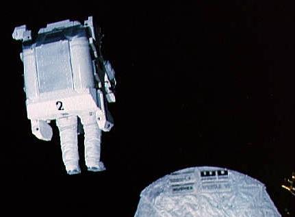
Credit: Astronautix website
Would both Astronauts be wearing their respective MMUs simultaneously during the same EVA? I seriously doubt it...but who knows. If one seriously malfunctioned, I suppose you’d need the guy with the good one equally ‘suited up’ to render aid.
“The world’s first view of the Earth taken by a spacecraft from the vicinity of the Moon. The photo was transmitted to Earth by the United States Lunar Orbiter 1 and received at the NASA tracking station at Robledo De Chavela near Madrid, Spain. This crescent of the Earth was photographed August 23, at 16:35 GMT when the spacecraft was on its 16th orbit and just about to pass behind the Moon. This is the view the astronauts will have when they come around the backside of the moon and face the Earth. The Earth is shown on the left of the Photo with the U.S. east coast in the upper left, southern Europe toward the dark or night side of Earth, and Antarctica at the bottom of Earth crescent. The surface of the Moon is shown on the right side of the photo. Re-enhanced photograph - October 24, 1966.”
This photo is part of the historic & iconic ‘first photo of Earth from the moon’ panorama, comprising the middle ~third of it. The first photograph linked to below is NASA photo ID no. 66-H-1379, it being the right/upper (depending upon orientation) ~third of that panorama. Could that mean there’s a 66-H-1381…it being the left/lower ~third? I doubt it, that would be logical/make too much sense.
The conspicuous ‘dark’ crater to the right is Khvol’son. Hilbert E is at the lower right of the image. A portion of Hilbert Crater & its multiple other satellite craters are spread across the surface to the left of Hilbert E.
See also:
www.lpi.usra.edu/resources/lunarorbiter/frame/?1102
Specifically:
www.lpi.usra.edu/resources/lunarorbiter/images/preview/11...
Both above credit: LPI website
The Vienna Giant Ferris Wheel (Wiener Riesenrad) isn't merely an amusement ride; it's a voyage through history with a touch of cinematic allure. Soaring gracefully to an impressive height of 64.75 meters, it stands proudly as an iconic emblem of Vienna's skyline. Stepping into one of its historic cabins instantly transports you to a bygone era. These charming cabins, each boasting a spacious 7.3-meter diameter, have borne witness to over a century of history while retaining their original charm. Constructed in 1897 to celebrate Emperor Franz Joseph I's Golden Jubilee, the Ferris Wheel itself stands as a marvel of engineering. Its silver screen debut in the 1949 classic "The Third Man" catapulted the Ferris Wheel to cinematic stardom, forever etching its silhouette in the annals of film history – The Prater, Vienna, Austria